EP2834182B1 - Hebegeschirr - Google Patents
Hebegeschirr Download PDFInfo
- Publication number
- EP2834182B1 EP2834182B1 EP13736629.0A EP13736629A EP2834182B1 EP 2834182 B1 EP2834182 B1 EP 2834182B1 EP 13736629 A EP13736629 A EP 13736629A EP 2834182 B1 EP2834182 B1 EP 2834182B1
- Authority
- EP
- European Patent Office
- Prior art keywords
- axis
- jaw member
- latch
- lifting assembly
- load
- Prior art date
- Legal status (The legal status is an assumption and is not a legal conclusion. Google has not performed a legal analysis and makes no representation as to the accuracy of the status listed.)
- Active
Links
Images


Classifications
-
- B—PERFORMING OPERATIONS; TRANSPORTING
- B66—HOISTING; LIFTING; HAULING
- B66C—CRANES; LOAD-ENGAGING ELEMENTS OR DEVICES FOR CRANES, CAPSTANS, WINCHES, OR TACKLES
- B66C1/00—Load-engaging elements or devices attached to lifting or lowering gear of cranes or adapted for connection therewith for transmitting lifting forces to articles or groups of articles
- B66C1/10—Load-engaging elements or devices attached to lifting or lowering gear of cranes or adapted for connection therewith for transmitting lifting forces to articles or groups of articles by mechanical means
- B66C1/22—Rigid members, e.g. L-shaped members, with parts engaging the under surface of the loads; Crane hooks
- B66C1/34—Crane hooks
- B66C1/36—Crane hooks with means, e.g. spring-biased detents, for preventing inadvertent disengagement of loads
-
- B—PERFORMING OPERATIONS; TRANSPORTING
- B66—HOISTING; LIFTING; HAULING
- B66C—CRANES; LOAD-ENGAGING ELEMENTS OR DEVICES FOR CRANES, CAPSTANS, WINCHES, OR TACKLES
- B66C1/00—Load-engaging elements or devices attached to lifting or lowering gear of cranes or adapted for connection therewith for transmitting lifting forces to articles or groups of articles
- B66C1/10—Load-engaging elements or devices attached to lifting or lowering gear of cranes or adapted for connection therewith for transmitting lifting forces to articles or groups of articles by mechanical means
- B66C1/22—Rigid members, e.g. L-shaped members, with parts engaging the under surface of the loads; Crane hooks
- B66C1/34—Crane hooks
Definitions
- the present invention relates to cranes, hoists, and other overhead lifting devices. More specifically, the invention relates to a lifting assembly that is selectively engaged with a load to be lifted.
- Lifting equipment often includes a rigid hook for engaging and suspending a strap, chain, or trunnion that is coupled to the load.
- the hook can be large, heavy, and difficult for an operator to manually manipulate. Where access is limited, and especially where hazardous or nuclear materials are present, the acts of hooking and unhooking the load can be difficult and dangerous.
- US 5 114 200 A discloses a lifting assembly comprising: a link member suspended from a base along a vertical axis; and a jaw member pivotally coupled to the link member about a pivot axis, whereby the jaw member defines a cam portion having a straight cam surface such that engaging the cam surface with a load by lowering the lifting apparatus rotates a portion of the jaw member into alignment with a mating surface of a latch mounted on the link member, the jaw member further including a hooking portion and a suspension portion disposed between the hooking portion and the cam portion; wherein the hooking portion includes a receiving surface that guides the jaw member into engagement with the load when hooking the load.
- the invention provides a lifting assembly.
- the lifting assembly includes a link member defining a pivot axis and a latch axis.
- the lifting assembly also includes a latch pin and a jaw member.
- the jaw member is pivotally coupled to the link member about the pivot axis and selectively fixedly coupled to the link member about the latch axis by the latch pin.
- the jaw member defines a cam surface. Engaging the cam surface with a load rotates a portion of the jaw member into alignment with the latch axis, such that the latch pin may be received by the jaw member and the link member.
- the invention provides a method of selectively engaging a load to a lifting apparatus.
- a jaw member is pivotally coupled to a link member about a pivot axis.
- the jaw member is rotated about the pivot axis, thereby exposing a hook portion of the jaw member.
- a trunnion of the load is hooked with the hook portion.
- a cam-surface of the jaw member is lowered upon the trunnion, thereby rotating the jaw member into alignment with a latch axis of the link member.
- the jaw member is latched to the link member by extending a latch member through the jaw member and the link member along the latch axis.
- a lifting assembly 10 includes an upper assembly 14, a swivel 18, a link assembly 22, and a jaw member 26.
- the lifting assembly 10 is configured to engage a load for lifting and movement. More specifically, the lifting assembly 10 is configured to engage a trunnion 30 ( FIGS. 3-5 ) of a load.
- the trunnion 30 may be coupled, for example, to a nuclear fuel assembly, a nuclear fuel cask, or other load.
- the upper assembly 14 includes a body 34 that rotatably supports an arrangement of pulleys 38.
- the pulleys 38 facilitate raising and lowering the lifting assembly 10, including an attached load, when used in conjunction with a wire rope (i.e. a metallic cable) and a hoist motor (not shown).
- the swivel 18 is rotatably coupled to the body 34.
- the swivel 18 includes a connecting portion 50 for pivotally supporting the link assembly 22. More specifically, the connecting portion 50 includes a first support extension 54 and a second support extension 58. The first support extension 54 and the second support extension 58 each define a swivel aperture 62.
- the link assembly 22 includes a link body 66.
- the link body 66 includes a support portion 70 for pivotal engagement with the support extensions 54 and 58 of the swivel 18.
- the support portion 70 defines a link support aperture 74 ( FIGS. 3-5 ). With the support portion disposed between the first support extension 54 and the second support extension 58, the link support aperture 74 is aligned with the swivel apertures 62 along a link pivot axis 78 ( FIG. 1 ).
- a link pivot pin 82 is inserted through the swivel apertures 62 and the link support aperture 74 to 18 pivotally couple the link assembly 22 to the swivel 18.
- a link pivot retainer plate 86 is fixedly coupled to the support portion 50 to inhibit the link pivot pin 82 from movement.
- the link body 66 further includes a first leg portion 90 and a second leg portion 94.
- the first leg portion 90 defines a first jaw cutout 98 for receiving a portion of the jaw member 26.
- the first leg portion 90 further defines a link pivot aperture 104 oriented along a jaw pivot axis 108.
- the jaw pivot axis 108 is substantially parallel to the link pivot axis 78.
- a jaw pivot pin 112 is disposed within the jaw pivot aperture 108.
- a jaw pivot retainer plate 116 is fixedly coupled to the link body 66 to inhibit the jaw pivot pin 112 from movement.
- the second leg portion 94 defines a second jaw cutout 120 for receiving a portion of the jaw member 26.
- the second leg portion 94 further defines a link latch aperture 124 oriented along a jaw latch axis 128.
- the jaw latch axis 128 is substantially parallel to the link pivot axis 78 and jaw pivot axis 108.
- a trunnion recess 132 is defined in the link body 66, between the first leg portion 90 and the second leg portion 94. As illustrated in FIG. 4 , the trunnion recess 132 is sized and configured to slidably receive the trunnion 30 during actuation of the jaw member 26. Referring to FIGS. 1 and 2 , the trunnion recess 132 includes substantially parallel wall portions 136, an inlet portion 140 with fillets 144 for smooth engagement with the trunnion 30, and a radiused end portion 148.
- the link assembly 22 further includes a latch pin cover 152.
- the latch pin cover 152 is pivotally coupled to the link body 66, more specifically, to the second leg portion 94. In a closed position ( FIG. 1 ), the latch pin cover 152 extends across the second leg portion 94 to obstruct both ends of the link latch aperture 124. In an open position ( FIG. 2 ), the latch pin cover 152 is rotated away from the second leg portion 94, thereby exposing the link latch aperture 124. With the link latch aperture 124 exposed, a jaw latch pin 156 may be selectively inserted or removed from the link latch aperture 124, along the jaw latch axis 128.
- a detachable pin handle 160 is provided with the lifting assembly 10.
- the pin handle 160 includes a T-shaped body 164 with an end portion 168.
- the end portion 168 may be selectively engaged with a corresponding aperture 172 of the jaw latch pin 156 to facilitate inserting and withdrawing the jaw latch pin 156 from the link latch aperture 124.
- the pin aperture 172 includes a female threaded portion and the end portion 168 of the pin handle 160 includes a male threaded portion.
- the pin handle 160 is detachably coupled to the link body 66.
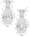
- the jaw member 26 With the jaw latch pin 156 removed, the jaw member 26 is rotatable between a closed position ( FIGS. 1 , 4 and 5 ) and an open position ( FIG. 3 and broken line illustration of FIG. 2 ).
- the jaw member 26 includes a hooking portion 176, a cam portion 180, and a suspension portion 184 disposed between the hooking portion 176 and the cam portion 180.
- the hooking portion 176 includes a jaw latch aperture 188.
- the jaw latch aperture 188 is sized to slidably receive the jaw latch pin 156.
- the jaw latch pin 156 may be inserted through the link latch aperture 124 and jaw latch aperture 188 along the jaw latch axis 128 ( FIG. 1 ).
- the hooking portion 176 further defines a receiving surface 192.
- the receiving surface 192 is configured to guide the jaw member 26 into engagement with the trunnion 30 when hooking a load.
- the receiving surface 192 includes a rounded end portion 196 and extends to the suspension portion 184. With the jaw member 26 in the open position, the receiving surface 192 has a downward slope ⁇ relative to a horizontal axis 202.
- the cam portion 180 includes a jaw pivot aperture 206.
- the jaw pivot aperture 206 is sized to slidably receive the jaw pivot pin 112, such that the jaw member 26 is pivotally coupled to the first leg portion 90 about the jaw pivot pin 112.
- the cam portion 206 also includes a cam tip 210 and a cam surface 214. As shown in FIG. 3 , the cam tip 210 contacts the wall portion 136 of the trunnion recess 132 when the jaw member 26 is in an open position, thereby stabilizing the jaw member 26 to facilitate hooking and unloading of a load.
- the cam surface 214 is disposed substantially opposite, and substantially facing, the receiving surface 192.
- the cam surface 214 has a curvature 218 between the suspension portion 184 and the cam tip 210.
- the trunnion 30 is substantially aligned with the trunnion recess 132 of the link body 66.
- contact between the cam surface 214 and the trunnion 30 causes the jaw member 26 to rotate about jaw pivot axis 108.
- the suspension portion 184 includes a suspension surface 222.
- the suspension surface 222 has a radius R corresponding to the trunnion 30, such that forces from the load are distributed on the suspension surface 222.
- FIGS. 3-5 In order to unload the lifting assembly 10, the steps of FIGS. 3-5 are reversed. With the load safely positioned, the lifting assembly 10 is lowered upon the trunnion 30, as illustrated in Fig. 4 . The latch pin cover 152 is opened and the jaw latch pin 156 is withdrawn, as illustrated in FIG. 1 . With the latch pin 156 withdrawn, the jaw member 26 rotates to the open position, as shown in FIG. 3 , and the jaw member 26 is unhooked from the trunnion 30.
Landscapes
- Engineering & Computer Science (AREA)
- Mechanical Engineering (AREA)
- Load-Engaging Elements For Cranes (AREA)
Claims (15)
- Hebebaugruppe (10), umfassend:- ein Verbindungsglied (22), das von einer oberen Baugruppe (14) längs einer vertikalen Achse herabhängt; und- ein Backenglied (26), das um eine Schwenkachse (108) schwenkbar mit dem Verbindungsglied (22) gekoppelt ist,dadurch gekennzeichnet, dass das Backenglied (26) einen Kurvenabschnitt (180) mit einer Kurvenoberfläche (214) definiert, so dass ein in Eingriff bringen der Kurvenoberfläche mit einer Last durch Senken der Hebebaugruppe (10) einen Abschnitt des Backengliedes (26) in Flucht mit einer Klinkenachse (128) dreht, wobei die Schwenkachse (108) und die Klinkenachse (128) auf gegenüberliegenden Seiten der vertikalen Achse angeordnet sind, wodurch ein Klinkenstift (156) von dem Backenglied (26) und dem Verbindungsglied (22) aufgenommen werden kann, wobei das Backenglied weiter einen einhakenden Abschnitt (176) und einen Anhängeabschnitt (184) beinhaltet, der zwischen dem einhakenden Abschnitt (176) und dem Kurvenabschnitt (180) angeordnet ist; wobei der einhakende Abschnitt (176) eine Aufnahmefläche (192) beinhaltet, die das Backenglied (26) in Eingriff mit der Last führt, wenn die Last eingehakt wird, die Aufnahmefläche im Wesentlichen dem Kurvenabschnitt (180) gegenüberliegt, und wobei die Aufnahmefläche (192), wenn sich das Backenglied (26) in einer geöffneten, aufgeklinkten Stellung befindet, eine nach unten gerichtete Neigung (θ) aufweist, die sich von dem einhakenden Abschnitt (176) in Richtung des Anhängeabschnittes (184) gegenüber einer Achse, die lotrecht zu der vertikalen Achse ist, erstreckt.
- Hebebaugruppe gemäß Anspruch 1, dadurch gekennzeichnet, dass die Aufnahmefläche (192) im Wesentlichen der Kurvenoberfläche (214) des Kurvenabschnittes (180) gegenüberliegt.
- Hebebaugruppe gemäß Anspruch 1, dadurch gekennzeichnet, dass der einhakende Abschnitt (176) eine Öffnung (188) zur Aufnahme des Klinkenstiftes (156) definiert.
- Hebebaugruppe gemäß Anspruch 1, dadurch gekennzeichnet, dass der Anhängeabschnitt (184) eine Anhängefläche (222) aufweist, wobei die Anhängefläche (222) eingerichtet ist, die Last bei einem Heben zu tragen, und wobei die Anhängefläche (222) eingerichtet ist, einen Zapfen (30) der Last aufzunehmen.
- Hebebaugruppe gemäß Anspruch 1, dadurch gekennzeichnet, dass sie ferner einen Drehzapfen (112) umfasst, und wobei der Kurvenabschnitt (180) eine Öffnung (206) zur Aufnahme des Drehzapfens (112) definiert, wobei das Backenglied (26) um den Drehzapfen (112) schwenkbar mit dem Verbindungsglied (22) gekoppelt ist.
- Hebebaugruppe gemäß Anspruch 1, dadurch gekennzeichnet, dass das Backenglied (26) schwenkbar zwischen einer ersten Stellung, in der das Backenglied (26) zur Aufnahme eines Zapfens (30) der Last geöffnet ist, und einer zweiten Stellung ist, in der der Zapfen (30) im Wesentlichen von dem Backenglied (26) und dem Verbindungsglied (22) aufgenommen ist.
- Hebebaugruppe gemäß Anspruch 1, dadurch gekennzeichnet, dass das Verbindungsglied eine zwischen der Schwenkachse und der Klinkenachse vorgesehene Aussparung definiert, wobei die Aussparung eingerichtet ist, einen Zapfen (30) der Last aufzunehmen, und wobei der Zapfen (30) mit der Kurvenoberfläche (214) in Eingriff ist, wenn der Zapfen (30) in der Aussparung aufgenommen ist.
- Hebebaugruppe gemäß Anspruch 1, dadurch gekennzeichnet, dass sie ferner den Klinkenstift (156) umfasst, wobei das Backenglied (26) wahlweise fest mit dem Verbindungsglied (22) durch den Klinkenstift (156) um die Klinkenachse gekoppelt ist, und die weiter ein Abdeckglied (152) umfasst, das beweglich mit dem Verbindungsglied (22) gekoppelt ist, wobei das Abdeckglied (152) zwischen einer ersten Stellung, bei der das Abdeckglied (152) den Klinkenstift (156) im Wesentlichen hindert, von dem Backenglied (26) zurückgezogen zu werden, und einer zweiten Stellung bewegbar ist, bei der der Klinkenstift (156) längs der Klinkenachse frei zurückgezogen werden kann, und wobei das Abdeckglied (152) schwenkbar mit dem Verbindungsglied (22) für eine Bewegung zwischen der ersten Stellung und der zweiten Stellung gekoppelt ist.
- Hebebaugruppe gemäß Anspruch 1, dadurch gekennzeichnet, dass sie ferner ein Schwenkglied umfasst, wobei das Verbindungsglied (22) schwenkbar mit dem Schwenkglied (42) gekoppelt ist.
- Hebebaugruppe gemäß Anspruch 1, dadurch gekennzeichnet, dass das Verbindungsglied (22) einen ersten, die Schwenkachse definierenden Schenkelabschnitt (90) und eine zweiten, die Klinkenachse definierenden Schenkelabschnitt (94) aufweist.
- Hebebaugruppe gemäß Anspruch 1, dadurch gekennzeichnet, dass eine Strecke, die sich quer zu der vertikalen Achse zwischen der Schwenkachse und der vertikalen Achse erstreckt, im Wesentlichen gleich einer sich quer zu der vertikalen Achse zwischen der Klinkenachse und der vertikalen Achse erstreckenden Strecke ist.
- Verfahren zum wahlweisen in Eingriff bringen einer Last mit einer Hebebaugruppe (10) mit einem Verbindungsglied (22), das längs einer vertikalen Achse herabhängt, und einem Backenglied (26), das schwenkbar mit dem Verbindungsglied (22) gekoppelt ist, dadurch gekennzeichnet, dass das Verfahren umfasst:- Drehen des Backengliedes (26) um eine Schwenkachse, wodurch ein hakender Abschnitt (176) des Backengliedes (26) freigegeben wird;- Anhängen der Last an dem hakenden Abschnitt (176);- Senken der Hebebaugruppe (10) während eine Kurvenoberfläche (214) des Backengliedes (26) mit der Last in Eingriff kommt, wodurch das Backenglied (22) in Flucht mit einer Klinkenachse des Verbindungsgliedes (22) dreht, wobei die Schwenkachse und die Klinkenachse auf gegenüberliegenden Seiten der vertikalen Achse angeordnet sind; und- Zuklinken des Backengliedes (26) an das Verbindungsglied (22);- wobei das Backenglied (26) einen Kurvenabschnitt (180) und einen Anhängeabschnitt (184) beinhaltet, der zwischen dem hakenden Abschnitt (176) und dem Kurvenabschnitt (180) angeordnet ist, wobei der Kurvenabschnitt (180) eine Kurvenoberfläche (214) definiert, und wobei der Schritt des Anhängens ein Führen des Backengliedes (26) in Eingriff mit der Last mit einer Aufnahmefläche (192) auf dem hakenden Abschnitt (176) beinhaltet, und wobei die Aufnahmefläche (192), wenn sich das Backenglied (26) in einer geöffneten, aufgeklinkten Stellung befindet, eine nach unten gerichtete Neigung (θ) aufweist, die sich von dem einhakenden Abschnitt (176) in Richtung des Anhängeabschnittes (184) gegenüber einer Achse, die lotrecht zu der vertikalen Achse ist, erstreckt.
- Verfahren gemäß Anspruch 12, dadurch gekennzeichnet, dass es weiter umfasst:- Unterstützen der Last, um einen Schlupf zwischen dem Backenglied (26) und der Last zu erzeugen;- Anheben der Hebebaugruppe (10), wodurch es dem Backenglied (26) ermöglicht wird, um die Schwenkachse zu drehen; und- Zurückziehen des Hakenabschnittes von der Last.
- Verfahren gemäß Anspruch 12, dadurch gekennzeichnet, dass eine Strecke, die sich quer zu der vertikalen Achse zwischen der Schwenkachse und der vertikalen Achse erstreckt, im Wesentlichen gleich einer sich quer zu der vertikalen Achse zwischen der Klinkenachse und der vertikalen Achse erstreckenden Strecke bleibt.
- Verfahren gemäß Anspruch 12, dadurch gekennzeichnet, dass es weiter ein bewegliches Koppeln eines Abdeckgliedes (152) mit dem Verbindungsglied (22) umfasst, wobei das Abdeckglied (152) zwischen einer ersten Stellung, bei der das Abdeckglied (152) den Klinkenstift im Wesentlichen hindert, von dem Backenglied (26) zurückgezogen zu werden, und einer zweiten Stellung bewegbar ist, bei der das Klinkenglied frei entlang der Klinkenachse zurückgezogen werden kann.
Applications Claiming Priority (2)
| Application Number | Priority Date | Filing Date | Title |
|---|---|---|---|
| US13/440,011 US8523253B1 (en) | 2012-04-05 | 2012-04-05 | Lifting assembly |
| PCT/IB2013/001174 WO2013150383A1 (en) | 2012-04-05 | 2013-04-03 | Lifting assembly |
Publications (2)
| Publication Number | Publication Date |
|---|---|
| EP2834182A1 EP2834182A1 (de) | 2015-02-11 |
| EP2834182B1 true EP2834182B1 (de) | 2016-11-02 |
Family
ID=48783287
Family Applications (1)
| Application Number | Title | Priority Date | Filing Date |
|---|---|---|---|
| EP13736629.0A Active EP2834182B1 (de) | 2012-04-05 | 2013-04-03 | Hebegeschirr |
Country Status (3)
| Country | Link |
|---|---|
| US (3) | US8523253B1 (de) |
| EP (1) | EP2834182B1 (de) |
| WO (1) | WO2013150383A1 (de) |
Families Citing this family (13)
| Publication number | Priority date | Publication date | Assignee | Title |
|---|---|---|---|---|
| US8523253B1 (en) | 2012-04-05 | 2013-09-03 | Konecranes Plc. | Lifting assembly |
| US11104438B2 (en) | 2016-09-09 | 2021-08-31 | Wing Aviation Llc | Payload coupling apparatus for UAV and method of delivering a payload |
| US10793274B2 (en) | 2016-09-09 | 2020-10-06 | Wing Aviation Llc | Payload coupling apparatus for UAV and method of delivering a payload |
| CN108529423B (zh) * | 2018-05-17 | 2024-01-30 | 中建七局安装工程有限公司 | 一种自动脱钩h型钢专用吊钩 |
| US10815105B2 (en) | 2018-06-15 | 2020-10-27 | Arrow Acquisition, Llc | Quick connect system for industrial and construction equipment |
| CN109264570A (zh) * | 2018-12-01 | 2019-01-25 | 佛山市南海雅事达模型有限公司 | 一种智能无人起吊系统 |
| US11180263B2 (en) * | 2020-04-06 | 2021-11-23 | Workhorse Group Inc. | Flying vehicle systems and methods |
| US11667402B2 (en) | 2020-09-08 | 2023-06-06 | Wing Aviation Llc | Landing pad with charging and loading functionality for unmanned aerial vehicle |
| US11440679B2 (en) * | 2020-10-27 | 2022-09-13 | Cowden Technologies, Inc. | Drone docking station and docking module |
| CN114084792B (zh) * | 2021-12-14 | 2023-08-11 | 河南省大方重型机器有限公司 | 一种具有自锁功能的起重机挂钩总成 |
| CN116281574B (zh) * | 2023-03-07 | 2023-10-27 | 张家港宏昌钢板有限公司 | 一种行车吊钩防脱装置 |
| US11787244B1 (en) * | 2023-05-22 | 2023-10-17 | qingdaohongmaijixieyouxiangongsi | Split trailer shackle |
| US12528583B2 (en) | 2023-06-09 | 2026-01-20 | Wing Aviation Llc | Payload retriever having multiple slots for use with a UAV |
Family Cites Families (43)
| Publication number | Priority date | Publication date | Assignee | Title |
|---|---|---|---|---|
| US261749A (en) | 1882-07-25 | Way moeeis | ||
| US1559849A (en) | 1925-11-03 | Alphonso g | ||
| US312714A (en) | 1885-02-24 | Boat-detaching apparatus | ||
| US706248A (en) * | 1902-04-15 | 1902-08-05 | Nicholas Merches | Draft attachment. |
| US1101113A (en) * | 1913-12-26 | 1914-06-23 | Harry A Attfield | Hook for life-boats and the like. |
| US1381405A (en) * | 1920-01-05 | 1921-06-14 | Forrest T Dunham | Shackle-hook |
| US1368647A (en) | 1920-06-02 | 1921-02-15 | Lena Myers | Automatic grab catch and release device |
| US1451324A (en) | 1921-11-07 | 1923-04-10 | Casamayor Marcos | Sling releaser for transporting apparatus |
| US1530010A (en) | 1924-10-01 | 1925-03-17 | Neilson Albert Howard | Safety hook |
| US1758722A (en) * | 1928-03-14 | 1930-05-13 | New England Trawler Equipment | Towing block |
| US2165413A (en) | 1939-01-21 | 1939-07-11 | James P Ratigan | Cable end link |
| US2395990A (en) | 1944-10-23 | 1946-03-05 | Ray G Boree | Lock hook |
| US2664175A (en) | 1945-04-28 | 1953-12-29 | Byron Jackson Co | Hook locking mechanism |
| US2476734A (en) * | 1948-01-16 | 1949-07-19 | Jellison Robert | Latch construction |
| US2608432A (en) | 1948-08-12 | 1952-08-26 | Coffing Hoist Company | Drop hook device |
| FR1180424A (fr) * | 1957-07-31 | 1959-06-04 | Stallinefabriken | Perfectionnement aux crochets de charge pour appareils de levage |
| NL255372A (de) | 1959-09-01 | |||
| US2987341A (en) * | 1959-10-28 | 1961-06-06 | Peck & Hale | Releasable hook |
| US3106420A (en) | 1960-04-11 | 1963-10-08 | Aeroquip Corp | Crane hook |
| GB1222952A (en) * | 1967-04-04 | 1971-02-17 | Harley Patents Int | Releasable fasteners |
| US3722943A (en) | 1971-05-12 | 1973-03-27 | J Kalua | Safety hook |
| US3930290A (en) * | 1974-11-22 | 1976-01-06 | Mangels Theodore F | Snap-shackle |
| US3911671A (en) * | 1975-02-12 | 1975-10-14 | Rafael Guillen | Snap link |
| JPS5815428Y2 (ja) * | 1975-09-27 | 1983-03-28 | 日本油脂株式会社 | キリハナシソウチ |
| GB1515764A (en) | 1975-10-06 | 1978-06-28 | Lewmar Marine Ltd | Shackles |
| JPS5245998A (en) | 1975-10-08 | 1977-04-12 | Toshiba Corp | Automatic deposit apparatus |
| JPS562024Y2 (de) * | 1975-12-12 | 1981-01-17 | ||
| JPS5833817B2 (ja) | 1975-12-27 | 1983-07-22 | 凸版印刷株式会社 | ケシヨウバンノセイゾウホウ |
| US4174132A (en) * | 1977-12-20 | 1979-11-13 | American Hoist & Derrick Company | Multiple position hook assembly |
| SU992386A1 (ru) | 1981-04-01 | 1983-01-30 | Краснодарский филиал Всесоюзного научно-исследовательского института по монтажным и специальным строительным работам | Саморасцепл ющеес грузозахватное устройство |
| US4379579A (en) | 1981-12-16 | 1983-04-12 | The B. F. Goodrich Company | Automatic locking and ejecting hook assembly |
| SE447472B (sv) | 1982-09-16 | 1986-11-17 | Kauko Antbacke | Lyftanordning innefattande en krok och ett i korkens upphegningsogla vridbart lagrat sperrorgan |
| US4632443A (en) * | 1983-07-13 | 1986-12-30 | Millridge Safety Developments Pty. Ltd. | Safety shackles |
| SE453074B (sv) | 1985-06-19 | 1988-01-11 | Ramnaes Konstr Tek Ab | Krokanordning |
| JPS63123580A (ja) | 1986-11-13 | 1988-05-27 | Mitsubishi Heavy Ind Ltd | 電子ビ−ム溶接装置 |
| JPH0535977Y2 (de) * | 1987-02-06 | 1993-09-10 | ||
| SE468913B (sv) | 1990-05-16 | 1993-04-05 | Igesto Ab | Saekerhetskrok |
| US5114200A (en) * | 1990-10-30 | 1992-05-19 | Gould Inc. | Gravity operated automatic hook |
| SE507623C3 (sv) | 1992-02-18 | 1998-08-10 | Wiklund Henry & Co | Lyftkrok med saekerhetsspaerr och moejlighet till automatisk lastfrigoering |
| US5634246A (en) * | 1995-11-20 | 1997-06-03 | The United States Of America As Represented By The Secretary Of The Navy | Snap swivel hook assembly incorporating ball swivel and recessed hook latch release mechanism |
| FR2754805B1 (fr) * | 1996-10-18 | 1998-12-31 | Soderel | Crochet de manutention a ouverture electromagnetique securisee |
| FR2929125B1 (fr) * | 2008-03-26 | 2013-03-15 | Jean Louis Pierre Rene Rocourt | Appareil de securisation des secours effectues par helitreuillage |
| US8523253B1 (en) | 2012-04-05 | 2013-09-03 | Konecranes Plc. | Lifting assembly |
-
2012
- 2012-04-05 US US13/440,011 patent/US8523253B1/en active Active
-
2013
- 2013-04-03 EP EP13736629.0A patent/EP2834182B1/de active Active
- 2013-04-03 WO PCT/IB2013/001174 patent/WO2013150383A1/en not_active Ceased
- 2013-08-06 US US13/959,831 patent/US8833822B2/en active Active
-
2014
- 2014-08-13 US US14/459,147 patent/US9061866B2/en active Active
Non-Patent Citations (1)
| Title |
|---|
| None * |
Also Published As
| Publication number | Publication date |
|---|---|
| US8833822B2 (en) | 2014-09-16 |
| US9061866B2 (en) | 2015-06-23 |
| WO2013150383A1 (en) | 2013-10-10 |
| US20140348627A1 (en) | 2014-11-27 |
| US8523253B1 (en) | 2013-09-03 |
| EP2834182A1 (de) | 2015-02-11 |
| US20130315700A1 (en) | 2013-11-28 |
Similar Documents
| Publication | Publication Date | Title |
|---|---|---|
| EP2834182B1 (de) | Hebegeschirr | |
| EP2231497B1 (de) | Haken | |
| US20170369285A1 (en) | Tool lifting devices, oilfield flange lifting safety devices, and related methods of use | |
| US4206940A (en) | Handling hook assembly | |
| US20020152593A1 (en) | Coupling self-locking hook | |
| US4530535A (en) | Cargo hook | |
| KR20160076616A (ko) | 반자동 샤클 | |
| JP2842780B2 (ja) | 円筒形重量物の吊具 | |
| CN217577993U (zh) | 水下快速脱钩装置 | |
| CN209685168U (zh) | 一种移动式舱口盖 | |
| JP2005041670A (ja) | ワーク吊り具 | |
| CN212953979U (zh) | 盖板起提装置 | |
| JP7600021B2 (ja) | 架線工事用吊り金車 | |
| CN219603053U (zh) | 一种自动闭锁吊具 | |
| JPH07247004A (ja) | ボックスパレット | |
| CN223357223U (zh) | 转运吊具 | |
| CN221565504U (zh) | 一种滑油滤器用起吊工装 | |
| CN216904053U (zh) | 一种可用无人机装卸的自锁跟斗滑车 | |
| RU2295487C1 (ru) | Захватное устройство для грузов с фигурной головкой | |
| CN215626198U (zh) | 管片吊具的卡爪锁定装置及管片吊具 | |
| CN220324893U (zh) | 地线卡钩的锁定装置 | |
| CN223575957U (zh) | 一种用于圆坯结晶器铜管的吊装装置 | |
| CN223722530U (zh) | 一种线材转移吊具 | |
| RU2389678C1 (ru) | Захват для двухтонных гирь и других изделий, имеющих монтажные петли | |
| JP2024140501A (ja) | トング装置 |
Legal Events
| Date | Code | Title | Description |
|---|---|---|---|
| PUAI | Public reference made under article 153(3) epc to a published international application that has entered the european phase |
Free format text: ORIGINAL CODE: 0009012 |
|
| 17P | Request for examination filed |
Effective date: 20141031 |
|
| AK | Designated contracting states |
Kind code of ref document: A1 Designated state(s): AL AT BE BG CH CY CZ DE DK EE ES FI FR GB GR HR HU IE IS IT LI LT LU LV MC MK MT NL NO PL PT RO RS SE SI SK SM TR |
|
| AX | Request for extension of the european patent |
Extension state: BA ME |
|
| DAX | Request for extension of the european patent (deleted) | ||
| 17Q | First examination report despatched |
Effective date: 20150828 |
|
| RAP1 | Party data changed (applicant data changed or rights of an application transferred) |
Owner name: KONECRANES GLOBAL CORPORATION |
|
| GRAP | Despatch of communication of intention to grant a patent |
Free format text: ORIGINAL CODE: EPIDOSNIGR1 |
|
| INTG | Intention to grant announced |
Effective date: 20160205 |
|
| GRAP | Despatch of communication of intention to grant a patent |
Free format text: ORIGINAL CODE: EPIDOSNIGR1 |
|
| INTG | Intention to grant announced |
Effective date: 20160512 |
|
| GRAJ | Information related to disapproval of communication of intention to grant by the applicant or resumption of examination proceedings by the epo deleted |
Free format text: ORIGINAL CODE: EPIDOSDIGR1 |
|
| GRAR | Information related to intention to grant a patent recorded |
Free format text: ORIGINAL CODE: EPIDOSNIGR71 |
|
| GRAS | Grant fee paid |
Free format text: ORIGINAL CODE: EPIDOSNIGR3 |
|
| INTC | Intention to grant announced (deleted) | ||
| GRAA | (expected) grant |
Free format text: ORIGINAL CODE: 0009210 |
|
| AK | Designated contracting states |
Kind code of ref document: B1 Designated state(s): AL AT BE BG CH CY CZ DE DK EE ES FI FR GB GR HR HU IE IS IT LI LT LU LV MC MK MT NL NO PL PT RO RS SE SI SK SM TR |
|
| INTG | Intention to grant announced |
Effective date: 20160928 |
|
| REG | Reference to a national code |
Ref country code: GB Ref legal event code: FG4D |
|
| REG | Reference to a national code |
Ref country code: AT Ref legal event code: REF Ref document number: 841625 Country of ref document: AT Kind code of ref document: T Effective date: 20161115 Ref country code: CH Ref legal event code: EP |
|
| REG | Reference to a national code |
Ref country code: IE Ref legal event code: FG4D |
|
| REG | Reference to a national code |
Ref country code: DE Ref legal event code: R096 Ref document number: 602013013505 Country of ref document: DE |
|
| PG25 | Lapsed in a contracting state [announced via postgrant information from national office to epo] |
Ref country code: LV Free format text: LAPSE BECAUSE OF FAILURE TO SUBMIT A TRANSLATION OF THE DESCRIPTION OR TO PAY THE FEE WITHIN THE PRESCRIBED TIME-LIMIT Effective date: 20161102 |
|
| REG | Reference to a national code |
Ref country code: NL Ref legal event code: MP Effective date: 20161102 |
|
| REG | Reference to a national code |
Ref country code: LT Ref legal event code: MG4D |
|
| REG | Reference to a national code |
Ref country code: AT Ref legal event code: MK05 Ref document number: 841625 Country of ref document: AT Kind code of ref document: T Effective date: 20161102 |
|
| PG25 | Lapsed in a contracting state [announced via postgrant information from national office to epo] |
Ref country code: LT Free format text: LAPSE BECAUSE OF FAILURE TO SUBMIT A TRANSLATION OF THE DESCRIPTION OR TO PAY THE FEE WITHIN THE PRESCRIBED TIME-LIMIT Effective date: 20161102 Ref country code: NO Free format text: LAPSE BECAUSE OF FAILURE TO SUBMIT A TRANSLATION OF THE DESCRIPTION OR TO PAY THE FEE WITHIN THE PRESCRIBED TIME-LIMIT Effective date: 20170202 Ref country code: NL Free format text: LAPSE BECAUSE OF FAILURE TO SUBMIT A TRANSLATION OF THE DESCRIPTION OR TO PAY THE FEE WITHIN THE PRESCRIBED TIME-LIMIT Effective date: 20161102 Ref country code: GR Free format text: LAPSE BECAUSE OF FAILURE TO SUBMIT A TRANSLATION OF THE DESCRIPTION OR TO PAY THE FEE WITHIN THE PRESCRIBED TIME-LIMIT Effective date: 20170203 Ref country code: SE Free format text: LAPSE BECAUSE OF FAILURE TO SUBMIT A TRANSLATION OF THE DESCRIPTION OR TO PAY THE FEE WITHIN THE PRESCRIBED TIME-LIMIT Effective date: 20161102 |
|
| PG25 | Lapsed in a contracting state [announced via postgrant information from national office to epo] |
Ref country code: PL Free format text: LAPSE BECAUSE OF FAILURE TO SUBMIT A TRANSLATION OF THE DESCRIPTION OR TO PAY THE FEE WITHIN THE PRESCRIBED TIME-LIMIT Effective date: 20161102 Ref country code: PT Free format text: LAPSE BECAUSE OF FAILURE TO SUBMIT A TRANSLATION OF THE DESCRIPTION OR TO PAY THE FEE WITHIN THE PRESCRIBED TIME-LIMIT Effective date: 20170302 Ref country code: IS Free format text: LAPSE BECAUSE OF FAILURE TO SUBMIT A TRANSLATION OF THE DESCRIPTION OR TO PAY THE FEE WITHIN THE PRESCRIBED TIME-LIMIT Effective date: 20170302 Ref country code: ES Free format text: LAPSE BECAUSE OF FAILURE TO SUBMIT A TRANSLATION OF THE DESCRIPTION OR TO PAY THE FEE WITHIN THE PRESCRIBED TIME-LIMIT Effective date: 20161102 Ref country code: FI Free format text: LAPSE BECAUSE OF FAILURE TO SUBMIT A TRANSLATION OF THE DESCRIPTION OR TO PAY THE FEE WITHIN THE PRESCRIBED TIME-LIMIT Effective date: 20161102 Ref country code: AT Free format text: LAPSE BECAUSE OF FAILURE TO SUBMIT A TRANSLATION OF THE DESCRIPTION OR TO PAY THE FEE WITHIN THE PRESCRIBED TIME-LIMIT Effective date: 20161102 Ref country code: HR Free format text: LAPSE BECAUSE OF FAILURE TO SUBMIT A TRANSLATION OF THE DESCRIPTION OR TO PAY THE FEE WITHIN THE PRESCRIBED TIME-LIMIT Effective date: 20161102 Ref country code: RS Free format text: LAPSE BECAUSE OF FAILURE TO SUBMIT A TRANSLATION OF THE DESCRIPTION OR TO PAY THE FEE WITHIN THE PRESCRIBED TIME-LIMIT Effective date: 20161102 |
|
| PG25 | Lapsed in a contracting state [announced via postgrant information from national office to epo] |
Ref country code: SK Free format text: LAPSE BECAUSE OF FAILURE TO SUBMIT A TRANSLATION OF THE DESCRIPTION OR TO PAY THE FEE WITHIN THE PRESCRIBED TIME-LIMIT Effective date: 20161102 Ref country code: RO Free format text: LAPSE BECAUSE OF FAILURE TO SUBMIT A TRANSLATION OF THE DESCRIPTION OR TO PAY THE FEE WITHIN THE PRESCRIBED TIME-LIMIT Effective date: 20161102 Ref country code: DK Free format text: LAPSE BECAUSE OF FAILURE TO SUBMIT A TRANSLATION OF THE DESCRIPTION OR TO PAY THE FEE WITHIN THE PRESCRIBED TIME-LIMIT Effective date: 20161102 Ref country code: CZ Free format text: LAPSE BECAUSE OF FAILURE TO SUBMIT A TRANSLATION OF THE DESCRIPTION OR TO PAY THE FEE WITHIN THE PRESCRIBED TIME-LIMIT Effective date: 20161102 Ref country code: EE Free format text: LAPSE BECAUSE OF FAILURE TO SUBMIT A TRANSLATION OF THE DESCRIPTION OR TO PAY THE FEE WITHIN THE PRESCRIBED TIME-LIMIT Effective date: 20161102 |
|
| REG | Reference to a national code |
Ref country code: DE Ref legal event code: R097 Ref document number: 602013013505 Country of ref document: DE |
|
| PG25 | Lapsed in a contracting state [announced via postgrant information from national office to epo] |
Ref country code: IT Free format text: LAPSE BECAUSE OF FAILURE TO SUBMIT A TRANSLATION OF THE DESCRIPTION OR TO PAY THE FEE WITHIN THE PRESCRIBED TIME-LIMIT Effective date: 20161102 Ref country code: BE Free format text: LAPSE BECAUSE OF FAILURE TO SUBMIT A TRANSLATION OF THE DESCRIPTION OR TO PAY THE FEE WITHIN THE PRESCRIBED TIME-LIMIT Effective date: 20161102 Ref country code: BG Free format text: LAPSE BECAUSE OF FAILURE TO SUBMIT A TRANSLATION OF THE DESCRIPTION OR TO PAY THE FEE WITHIN THE PRESCRIBED TIME-LIMIT Effective date: 20170202 Ref country code: SM Free format text: LAPSE BECAUSE OF FAILURE TO SUBMIT A TRANSLATION OF THE DESCRIPTION OR TO PAY THE FEE WITHIN THE PRESCRIBED TIME-LIMIT Effective date: 20161102 |
|
| PLBE | No opposition filed within time limit |
Free format text: ORIGINAL CODE: 0009261 |
|
| STAA | Information on the status of an ep patent application or granted ep patent |
Free format text: STATUS: NO OPPOSITION FILED WITHIN TIME LIMIT |
|
| 26N | No opposition filed |
Effective date: 20170803 |
|
| REG | Reference to a national code |
Ref country code: DE Ref legal event code: R119 Ref document number: 602013013505 Country of ref document: DE |
|
| PG25 | Lapsed in a contracting state [announced via postgrant information from national office to epo] |
Ref country code: SI Free format text: LAPSE BECAUSE OF FAILURE TO SUBMIT A TRANSLATION OF THE DESCRIPTION OR TO PAY THE FEE WITHIN THE PRESCRIBED TIME-LIMIT Effective date: 20161102 |
|
| REG | Reference to a national code |
Ref country code: CH Ref legal event code: PL |
|
| GBPC | Gb: european patent ceased through non-payment of renewal fee |
Effective date: 20170403 |
|
| REG | Reference to a national code |
Ref country code: IE Ref legal event code: MM4A |
|
| REG | Reference to a national code |
Ref country code: FR Ref legal event code: ST Effective date: 20171229 |
|
| PG25 | Lapsed in a contracting state [announced via postgrant information from national office to epo] |
Ref country code: DE Free format text: LAPSE BECAUSE OF NON-PAYMENT OF DUE FEES Effective date: 20171103 Ref country code: MC Free format text: LAPSE BECAUSE OF FAILURE TO SUBMIT A TRANSLATION OF THE DESCRIPTION OR TO PAY THE FEE WITHIN THE PRESCRIBED TIME-LIMIT Effective date: 20161102 Ref country code: FR Free format text: LAPSE BECAUSE OF NON-PAYMENT OF DUE FEES Effective date: 20170502 |
|
| PG25 | Lapsed in a contracting state [announced via postgrant information from national office to epo] |
Ref country code: GB Free format text: LAPSE BECAUSE OF NON-PAYMENT OF DUE FEES Effective date: 20170403 Ref country code: LI Free format text: LAPSE BECAUSE OF NON-PAYMENT OF DUE FEES Effective date: 20170430 Ref country code: CH Free format text: LAPSE BECAUSE OF NON-PAYMENT OF DUE FEES Effective date: 20170430 Ref country code: LU Free format text: LAPSE BECAUSE OF NON-PAYMENT OF DUE FEES Effective date: 20170403 |
|
| REG | Reference to a national code |
Ref country code: FR Ref legal event code: PLFP Year of fee payment: 6 |
|
| REG | Reference to a national code |
Ref country code: DE Ref legal event code: R073 Ref document number: 602013013505 Country of ref document: DE |
|
| PG25 | Lapsed in a contracting state [announced via postgrant information from national office to epo] |
Ref country code: IE Free format text: LAPSE BECAUSE OF NON-PAYMENT OF DUE FEES Effective date: 20170403 |
|
| REG | Reference to a national code |
Ref country code: FR Ref legal event code: RN Effective date: 20180406 |
|
| REG | Reference to a national code |
Ref country code: DE Ref legal event code: R074 Ref document number: 602013013505 Country of ref document: DE |
|
| REG | Reference to a national code |
Ref country code: DE Ref legal event code: R074 Ref document number: 602013013505 Country of ref document: DE |
|
| REG | Reference to a national code |
Ref country code: FR Ref legal event code: FC Effective date: 20180614 |
|
| REG | Reference to a national code |
Ref country code: GB Ref legal event code: S28 Free format text: APPLICATION FILED |
|
| PG25 | Lapsed in a contracting state [announced via postgrant information from national office to epo] |
Ref country code: DE Free format text: LAPSE BECAUSE OF NON-PAYMENT OF DUE FEES Effective date: 20171103 |
|
| PGRI | Patent reinstated in contracting state [announced from national office to epo] |
Ref country code: DE Effective date: 20180628 |
|
| REG | Reference to a national code |
Ref country code: GB Ref legal event code: S28 Free format text: RESTORATION ALLOWED Effective date: 20180806 |
|
| PG25 | Lapsed in a contracting state [announced via postgrant information from national office to epo] |
Ref country code: FR Free format text: LAPSE BECAUSE OF NON-PAYMENT OF DUE FEES Effective date: 20170502 |
|
| PGRI | Patent reinstated in contracting state [announced from national office to epo] |
Ref country code: FR Effective date: 20180618 |
|
| PG25 | Lapsed in a contracting state [announced via postgrant information from national office to epo] |
Ref country code: MT Free format text: LAPSE BECAUSE OF NON-PAYMENT OF DUE FEES Effective date: 20170403 |
|
| PG25 | Lapsed in a contracting state [announced via postgrant information from national office to epo] |
Ref country code: HU Free format text: LAPSE BECAUSE OF FAILURE TO SUBMIT A TRANSLATION OF THE DESCRIPTION OR TO PAY THE FEE WITHIN THE PRESCRIBED TIME-LIMIT; INVALID AB INITIO Effective date: 20130403 |
|
| PG25 | Lapsed in a contracting state [announced via postgrant information from national office to epo] |
Ref country code: CY Free format text: LAPSE BECAUSE OF FAILURE TO SUBMIT A TRANSLATION OF THE DESCRIPTION OR TO PAY THE FEE WITHIN THE PRESCRIBED TIME-LIMIT Effective date: 20161102 |
|
| PG25 | Lapsed in a contracting state [announced via postgrant information from national office to epo] |
Ref country code: MK Free format text: LAPSE BECAUSE OF FAILURE TO SUBMIT A TRANSLATION OF THE DESCRIPTION OR TO PAY THE FEE WITHIN THE PRESCRIBED TIME-LIMIT Effective date: 20161102 |
|
| PG25 | Lapsed in a contracting state [announced via postgrant information from national office to epo] |
Ref country code: TR Free format text: LAPSE BECAUSE OF FAILURE TO SUBMIT A TRANSLATION OF THE DESCRIPTION OR TO PAY THE FEE WITHIN THE PRESCRIBED TIME-LIMIT Effective date: 20161102 |
|
| PG25 | Lapsed in a contracting state [announced via postgrant information from national office to epo] |
Ref country code: AL Free format text: LAPSE BECAUSE OF FAILURE TO SUBMIT A TRANSLATION OF THE DESCRIPTION OR TO PAY THE FEE WITHIN THE PRESCRIBED TIME-LIMIT Effective date: 20161102 |
|
| P01 | Opt-out of the competence of the unified patent court (upc) registered |
Effective date: 20230428 |
|
| PGFP | Annual fee paid to national office [announced via postgrant information from national office to epo] |
Ref country code: DE Payment date: 20250417 Year of fee payment: 13 |
|
| PGFP | Annual fee paid to national office [announced via postgrant information from national office to epo] |
Ref country code: GB Payment date: 20250423 Year of fee payment: 13 |
|
| PGFP | Annual fee paid to national office [announced via postgrant information from national office to epo] |
Ref country code: FR Payment date: 20250422 Year of fee payment: 13 |