EP2832980A1 - Motorgehäuse einer Brennkraftmaschine sowie damit ausgestattete Brennkraftmaschine - Google Patents
Motorgehäuse einer Brennkraftmaschine sowie damit ausgestattete Brennkraftmaschine Download PDFInfo
- Publication number
- EP2832980A1 EP2832980A1 EP14179464.4A EP14179464A EP2832980A1 EP 2832980 A1 EP2832980 A1 EP 2832980A1 EP 14179464 A EP14179464 A EP 14179464A EP 2832980 A1 EP2832980 A1 EP 2832980A1
- Authority
- EP
- European Patent Office
- Prior art keywords
- cylinder
- head unit
- cylinder block
- motor housing
- section
- Prior art date
- Legal status (The legal status is an assumption and is not a legal conclusion. Google has not performed a legal analysis and makes no representation as to the accuracy of the status listed.)
- Withdrawn
Links
- 238000002485 combustion reaction Methods 0.000 title claims description 46
- 239000000463 material Substances 0.000 claims description 53
- 238000007789 sealing Methods 0.000 claims description 26
- 238000001816 cooling Methods 0.000 claims description 24
- 230000007704 transition Effects 0.000 claims description 24
- 229910052782 aluminium Inorganic materials 0.000 claims description 11
- XAGFODPZIPBFFR-UHFFFAOYSA-N aluminium Chemical compound [Al] XAGFODPZIPBFFR-UHFFFAOYSA-N 0.000 claims description 11
- 239000002826 coolant Substances 0.000 claims description 7
- 229910001060 Gray iron Inorganic materials 0.000 claims description 5
- 230000004323 axial length Effects 0.000 claims description 4
- 238000002347 injection Methods 0.000 claims description 3
- 239000007924 injection Substances 0.000 claims description 3
- 239000000110 cooling liquid Substances 0.000 claims description 2
- 238000005266 casting Methods 0.000 description 15
- 230000008901 benefit Effects 0.000 description 13
- UQMRAFJOBWOFNS-UHFFFAOYSA-N butyl 2-(2,4-dichlorophenoxy)acetate Chemical compound CCCCOC(=O)COC1=CC=C(Cl)C=C1Cl UQMRAFJOBWOFNS-UHFFFAOYSA-N 0.000 description 8
- 238000013461 design Methods 0.000 description 7
- 238000010276 construction Methods 0.000 description 6
- 239000000243 solution Substances 0.000 description 4
- 239000007789 gas Substances 0.000 description 3
- 238000005304 joining Methods 0.000 description 3
- 238000004519 manufacturing process Methods 0.000 description 3
- 238000000926 separation method Methods 0.000 description 3
- 238000012546 transfer Methods 0.000 description 3
- 238000011161 development Methods 0.000 description 2
- 230000018109 developmental process Effects 0.000 description 2
- 238000006073 displacement reaction Methods 0.000 description 2
- 230000002349 favourable effect Effects 0.000 description 2
- 239000000446 fuel Substances 0.000 description 2
- 238000003780 insertion Methods 0.000 description 2
- 230000037431 insertion Effects 0.000 description 2
- 230000007774 longterm Effects 0.000 description 2
- 238000000034 method Methods 0.000 description 2
- 238000012545 processing Methods 0.000 description 2
- 230000003313 weakening effect Effects 0.000 description 2
- GHYOCDFICYLMRF-UTIIJYGPSA-N (2S,3R)-N-[(2S)-3-(cyclopenten-1-yl)-1-[(2R)-2-methyloxiran-2-yl]-1-oxopropan-2-yl]-3-hydroxy-3-(4-methoxyphenyl)-2-[[(2S)-2-[(2-morpholin-4-ylacetyl)amino]propanoyl]amino]propanamide Chemical compound C1(=CCCC1)C[C@@H](C(=O)[C@@]1(OC1)C)NC([C@H]([C@@H](C1=CC=C(C=C1)OC)O)NC([C@H](C)NC(CN1CCOCC1)=O)=O)=O GHYOCDFICYLMRF-UTIIJYGPSA-N 0.000 description 1
- 229910000639 Spring steel Inorganic materials 0.000 description 1
- 238000010521 absorption reaction Methods 0.000 description 1
- 230000009471 action Effects 0.000 description 1
- 230000005540 biological transmission Effects 0.000 description 1
- 230000015572 biosynthetic process Effects 0.000 description 1
- 230000008859 change Effects 0.000 description 1
- 230000001427 coherent effect Effects 0.000 description 1
- 239000000567 combustion gas Substances 0.000 description 1
- 229940125797 compound 12 Drugs 0.000 description 1
- 239000012809 cooling fluid Substances 0.000 description 1
- 238000009826 distribution Methods 0.000 description 1
- 229920001971 elastomer Polymers 0.000 description 1
- 239000000806 elastomer Substances 0.000 description 1
- 210000004907 gland Anatomy 0.000 description 1
- 230000017525 heat dissipation Effects 0.000 description 1
- 238000009434 installation Methods 0.000 description 1
- 238000003754 machining Methods 0.000 description 1
- 229910052751 metal Inorganic materials 0.000 description 1
- 239000002184 metal Substances 0.000 description 1
- 230000036316 preload Effects 0.000 description 1
- 238000002360 preparation method Methods 0.000 description 1
- 230000001105 regulatory effect Effects 0.000 description 1
- 239000003566 sealing material Substances 0.000 description 1
Images


Classifications
-
- F—MECHANICAL ENGINEERING; LIGHTING; HEATING; WEAPONS; BLASTING
- F02—COMBUSTION ENGINES; HOT-GAS OR COMBUSTION-PRODUCT ENGINE PLANTS
- F02F—CYLINDERS, PISTONS OR CASINGS, FOR COMBUSTION ENGINES; ARRANGEMENTS OF SEALINGS IN COMBUSTION ENGINES
- F02F7/00—Casings, e.g. crankcases
- F02F7/0021—Construction
-
- F—MECHANICAL ENGINEERING; LIGHTING; HEATING; WEAPONS; BLASTING
- F02—COMBUSTION ENGINES; HOT-GAS OR COMBUSTION-PRODUCT ENGINE PLANTS
- F02F—CYLINDERS, PISTONS OR CASINGS, FOR COMBUSTION ENGINES; ARRANGEMENTS OF SEALINGS IN COMBUSTION ENGINES
- F02F1/00—Cylinders; Cylinder heads
- F02F1/24—Cylinder heads
-
- F—MECHANICAL ENGINEERING; LIGHTING; HEATING; WEAPONS; BLASTING
- F02—COMBUSTION ENGINES; HOT-GAS OR COMBUSTION-PRODUCT ENGINE PLANTS
- F02F—CYLINDERS, PISTONS OR CASINGS, FOR COMBUSTION ENGINES; ARRANGEMENTS OF SEALINGS IN COMBUSTION ENGINES
- F02F1/00—Cylinders; Cylinder heads
- F02F1/002—Integrally formed cylinders and cylinder heads
-
- F—MECHANICAL ENGINEERING; LIGHTING; HEATING; WEAPONS; BLASTING
- F02—COMBUSTION ENGINES; HOT-GAS OR COMBUSTION-PRODUCT ENGINE PLANTS
- F02F—CYLINDERS, PISTONS OR CASINGS, FOR COMBUSTION ENGINES; ARRANGEMENTS OF SEALINGS IN COMBUSTION ENGINES
- F02F1/00—Cylinders; Cylinder heads
- F02F1/02—Cylinders; Cylinder heads having cooling means
- F02F1/10—Cylinders; Cylinder heads having cooling means for liquid cooling
- F02F1/14—Cylinders with means for directing, guiding or distributing liquid stream
-
- F—MECHANICAL ENGINEERING; LIGHTING; HEATING; WEAPONS; BLASTING
- F02—COMBUSTION ENGINES; HOT-GAS OR COMBUSTION-PRODUCT ENGINE PLANTS
- F02F—CYLINDERS, PISTONS OR CASINGS, FOR COMBUSTION ENGINES; ARRANGEMENTS OF SEALINGS IN COMBUSTION ENGINES
- F02F1/00—Cylinders; Cylinder heads
- F02F1/18—Other cylinders
-
- F—MECHANICAL ENGINEERING; LIGHTING; HEATING; WEAPONS; BLASTING
- F02—COMBUSTION ENGINES; HOT-GAS OR COMBUSTION-PRODUCT ENGINE PLANTS
- F02F—CYLINDERS, PISTONS OR CASINGS, FOR COMBUSTION ENGINES; ARRANGEMENTS OF SEALINGS IN COMBUSTION ENGINES
- F02F1/00—Cylinders; Cylinder heads
- F02F1/24—Cylinder heads
- F02F1/243—Cylinder heads and inlet or exhaust manifolds integrally cast together
-
- F—MECHANICAL ENGINEERING; LIGHTING; HEATING; WEAPONS; BLASTING
- F02—COMBUSTION ENGINES; HOT-GAS OR COMBUSTION-PRODUCT ENGINE PLANTS
- F02F—CYLINDERS, PISTONS OR CASINGS, FOR COMBUSTION ENGINES; ARRANGEMENTS OF SEALINGS IN COMBUSTION ENGINES
- F02F1/00—Cylinders; Cylinder heads
- F02F1/24—Cylinder heads
- F02F1/26—Cylinder heads having cooling means
- F02F1/36—Cylinder heads having cooling means for liquid cooling
- F02F1/40—Cylinder heads having cooling means for liquid cooling cylinder heads with means for directing, guiding, or distributing liquid stream
-
- F—MECHANICAL ENGINEERING; LIGHTING; HEATING; WEAPONS; BLASTING
- F02—COMBUSTION ENGINES; HOT-GAS OR COMBUSTION-PRODUCT ENGINE PLANTS
- F02F—CYLINDERS, PISTONS OR CASINGS, FOR COMBUSTION ENGINES; ARRANGEMENTS OF SEALINGS IN COMBUSTION ENGINES
- F02F11/00—Arrangements of sealings in combustion engines
-
- F—MECHANICAL ENGINEERING; LIGHTING; HEATING; WEAPONS; BLASTING
- F02—COMBUSTION ENGINES; HOT-GAS OR COMBUSTION-PRODUCT ENGINE PLANTS
- F02F—CYLINDERS, PISTONS OR CASINGS, FOR COMBUSTION ENGINES; ARRANGEMENTS OF SEALINGS IN COMBUSTION ENGINES
- F02F7/00—Casings, e.g. crankcases
-
- F—MECHANICAL ENGINEERING; LIGHTING; HEATING; WEAPONS; BLASTING
- F02—COMBUSTION ENGINES; HOT-GAS OR COMBUSTION-PRODUCT ENGINE PLANTS
- F02F—CYLINDERS, PISTONS OR CASINGS, FOR COMBUSTION ENGINES; ARRANGEMENTS OF SEALINGS IN COMBUSTION ENGINES
- F02F7/00—Casings, e.g. crankcases
- F02F7/0065—Shape of casings for other machine parts and purposes, e.g. utilisation purposes, safety
- F02F7/007—Adaptations for cooling
-
- F—MECHANICAL ENGINEERING; LIGHTING; HEATING; WEAPONS; BLASTING
- F02—COMBUSTION ENGINES; HOT-GAS OR COMBUSTION-PRODUCT ENGINE PLANTS
- F02F—CYLINDERS, PISTONS OR CASINGS, FOR COMBUSTION ENGINES; ARRANGEMENTS OF SEALINGS IN COMBUSTION ENGINES
- F02F2200/00—Manufacturing
Definitions
- the invention relates to a motor housing of an internal combustion engine, as well as an engine equipped with this engine housing, as indicated in the claims 1 and 16.
- an internal combustion engine in monobloc design in which at least one hollow cylinder with an inner raceway for a piston is designed together with at least one cylinder head as a one-piece casting or forms an integral cylinder head unit.
- the engine or cylinder block of the internal combustion engine is divided in a vertical plane along the in-line cylinder, whereby the cylinder block is formed of two half-shells with a vertical separation or joining plane. These half shells are dimensioned such that the cylinder head unit supporting or partially receiving, upper portion of the cylinder block, as well as the crankshaft housing forming, lower portion of the cylinder block are each defined in half by the two half-shells of the cylinder block construction.
- a first support zone is positioned approximately at the level of the cylinder bottom of the cylinder head unit, the cylinder head unit being supported on the half shells of the cylinder block via a horizontal support surface and an intermediate seal.
- a cooling channel for flowing through with a cooling medium is sealed by means of this seal against the external environment of the internal combustion engine.
- Another support zone with a further sealing element is formed in the immediate vicinity of the open end of the hollow cylinder of the cylinder head unit.
- a circumferential projection or a rib-like extension is formed on the outer wall of the hollow cylinder.
- This extension engages positively in a corresponding, groove-shaped recess on the inner sides of the two half-shells of the cylinder block.
- the two half-shells of the cylinder block are joined together and clamped to each other via transverse to the cylinder axis glands. Due to the positive engagement between the rib-like projections on the hollow cylinder and the groove-like depressions on the inner sides of the half-shells of Cylinder block, the cylinder head unit is fixed in the axial direction of the hollow cylinder relative to the cylinder block.
- a known monobloc engine is a cylinder head unit formed from a one-piece casting, in which a bushing for slidably guiding the piston is pressed.
- this cylinder head unit all inlet and outlet channels for the combustion air and for the exhaust gases and insertion openings for a spark plug or an injector are implemented.
- a cooling passage for passing a cooling medium is formed in the cylinder head unit.
- a crankshaft housing for receiving and supporting the crankshaft comprises in the lower end portion a circumferential holding web for connection to an oil sump forming the lower end of the engine.
- the crankshaft housing is closed in the downward direction, in particular designed as a hollow cylinder, wherein the cylinder axis is horizontal.
- the cylinder head unit When assembling the motor housing, the cylinder head unit is placed on the exclusively upwardly open crankcase and then biased against the crankshaft housing with a lying in the piston movement direction and reaching through the entire engine housing fitting, the screw heads are supported on the bottom closed bottom portion of the crankcase.
- WO 2004/111418 A1 is another monobloc design in which at least one hollow cylinder and at least one cylinder head are formed as a one-piece casting and thus are united to form a cylinder head unit.
- a piston liner is pressed into the cylinder head unit.
- the cylinder or engine block is a casting which comprises at least an upper portion of the crankshaft housing and on which crankshaft housing side walls are formed, which are pulled up to a plane above the cylinder head unit and form at least one bearing for at least one overhead camshaft for valve control.
- cooling channels are integrated, which are flowed through by a cooling fluid.
- the installation of the cylinder head unit in the cylinder block unit is carried out by axial insertion in the piston movement direction.
- cooling channels are self-contained integrated in each case a cast block and thus an internal casting core for the preparation of these parts is necessary. Furthermore, the proposed constructions place high demands on the casting technique. By made in the known embodiments space or space distribution between the cylinder head unit and the cylinder block unit, it is also hardly possible to produce the engine as possible weight-saving and cost-efficient.
- the present invention has for its object to provide a motor housing, which eliminates or reduces these quality and cost disadvantages and the risk of engine damage by occurring internal stresses. Another object of the invention is that the engine housing or an internal combustion engine equipped with it is functional for as long as possible and can achieve long service life.
- an engine housing with a cylinder block and a cylinder head unit which cylinder head unit is formed from a head portion and at least one integrally mitgegossenen hollow cylinder portion with internal piston running surface, wherein the hollow cylinder portion of the cylinder head unit at least partially in the cylinder block in the axial direction of the hollow cylinder portion is inserted, and wherein the cylinder head unit by means of at least one fastening element in the axial direction of the hollow cylinder portion is prestressed against the cylinder block.
- an optimized structural unit or an improved motor housing is formed, which represents a good basis for an internal combustion engine according to claim 16.
- a motor housing is provided with a cylinder block and a cylinder head unit, which cylinder head unit is formed from a head portion and at least one integrally mitgegossenen hollow cylinder portion with internal piston tread.
- the hollow cylinder portion of the cylinder head unit is in this case at least partially inserted into the cylinder block in the axial direction of the hollow cylinder section.
- the hollow cylinder portion forms on the inside thereof directly the sliding surface for a piston oscillating therein, so that an independent piston liner is obsolete.
- the cylinder head unit can be prestressed against the cylinder block with at least one fastening element in the axial direction of the hollow cylinder section.
- An advantage of the design according to the invention is that there is no separating or joining surface between the head section of the cylinder head unit and the one-piece cast hollow cylinder section, and therefore no cylinder head gasket is required to seal the combustion chamber.
- a particular advantage of the embodiment of the invention is that a simple motor mounting is possible by the Relativverschiebles the hollow cylinder section in the axial direction with respect to the cylinder block.
- relative displacements, which occur due to temperature changes at the contact surfaces or transition interfaces between the cylinder block and hollow cylinder section can be compensated to a great extent, so that mechanical stresses in the motor housing are prevented or minimized as much as possible.
- the specified structure is of particular advantage. It is also advantageous that due to the pretensionability of the cylinder head unit in the axial direction of the hollow cylinder section against the cylinder block, the cylinder head unit is precisely defined in its position relative to the cylinder block. In addition, the main forces occurring in the course of fuel combustion are intercepted in the motor housing in the main direction.
- wet cylinder liner or by the “wet piston guide bushing, in which the outer surface of the hollow cylinder can be directly in contact with the cooling medium, a good or rapid heat transfer to the cooling medium can be carried out, which also under high loads Internal combustion engine ensures good heat dissipation and cooling, so that a long service life and a good reliability of operation can be achieved.
- the provided in the subject invention redundancy of separate liners for the pistons, which bushings would be pressed into the hollow cylinder, thus favors the cooling performance and the cooling behavior relative to the engine cylinders and beyond a cost-effective design of the motor housing can be achieved.
- cooling channel for the passage of a cooling medium is formed, which cooling channel is sealed by means of at least one sealing element at a first interface between the head portion and the cylinder block relative to the outside of the motor housing, and by means at least one further sealing element is sealed at a further transition interface between the hollow cylinder portion and the cylinder block relative to a crankshaft housing for receiving a crankshaft.
- the cooling channel is not an internal chamber, which is integrated in one of the two castings.
- internal mandrels i. so-called lost mold cores, which are technically problematic and expensive, are unnecessary or reduced for the casting process.
- the cooling passage is formed immediately around the skirt portion of the hollow cylinder portion from the geometry or boundary surfaces of adjacent portions of the cylinder head unit and the cylinder block.
- the at least one sealing element is arranged at the further transition interface between the hollow cylinder section and the cylinder block offset by a height distance relative to a further sealing element of a adjacent hollow cylinder section. It is advantageous in this measure that the space or the distance between the individual hollow cylinder sections, ie the distance or the so-called cylinder gauge between the cylinders, can be made relatively small or narrow. As a result, the overall length of internal combustion engines with cylinders in series can be kept as short as possible. This is achieved by making the punctures for the Include sealing rings in the individual cylinders have a height offset to the punctures for receiving sealing rings in a neighboring cylinder.
- the punctures in the individual juxtaposed cylinders can thereby be made sufficiently deep, without causing excessive material weakening due to excessive constrictions of the gutter between immediately adjacent wooden cylinders.
- the height offset between punctures of adjacent cylinder parts can be chosen to be large enough to ensure a minimum thickness of material in the groove-shaped recesses in the gutter.
- transition surfaces at the first transition interface between the head section and the cylinder block and transition surfaces at the further transition interface between the hollow cylinder section and the cylinder block are aligned at an angle, in particular at right angles to each other. It is advantageous here that the corresponding parts are easy to produce in the course of the manufacturing process and a favorable mutual support or load transfer is achieved.
- the fastening element with which the cylinder head unit can be prestressed against the cylinder block in the axial direction of the hollow cylinder section, is provided or formed in addition to the application of a prestressing force to a bearing shell of a crankshaft bearing.
- the advantage here is that with reference to the vertical axis of the engine those parts which are highly loaded due to the internal combustion pressures in the engine, screwed together with as few screw or biased to each other, and thus results in a favorable force or absorption of the forces occurring.
- the assembly times for the motor housing can be kept as low as possible, so that a good basis for a cost-effective production is created.
- At least one is Bolt formed, which screws together the bearing shell for a main bearing of the crankshaft, the cylinder block and the cylinder head unit and joins together to form a one-piece assembly.
- the at least one fastening element is preferably anchored or screwed in the cylinder head section, while the screw head is supported on the bearing shell.
- the cylinder block is penetrated via a through hole from the shaft of the at least one fastening element.
- an axial length of the hollow cylinder section of the cylinder head unit is between 50% and 200%, in particular between 80% and 110%, preferably approximately 100%, of a wall height of the cylinder block.
- the hollow cylinder section in the region of its further transition interface to the cylinder block has an approximately cylindrical or conical outer circumferential surface and is accommodated without play in the cylinder block. It is advantageous that the hollow cylinder portion can be inserted in the axial direction in the cylinder block and positioned as scheduled or fixed. Furthermore, it is advantageous that due to the axial displaceability of the hollow cylinder portion relative to the cylinder block any relative displacements due to temperature-induced different thermal expansions can be compensated relatively free of tension.
- the cylinder head unit has a shoulder surface running normal to the axial direction of the hollow cylinder section, via which the cylinder head unit is supported on the cylinder block and can be pretensioned against the cylinder block.
- the advantage here is that by the alignment of this shoulder or support surface a simple processing is possible.
- an upper end face of the cylinder block in the axial direction of the hollow cylinder section lies approximately at the level of a plane receiving a cylinder bottom of the cylinder head unit.
- the cylinder head unit is formed from a first material having a first material density, and that the cylinder block is formed from a further material having a different material density than the first material.
- the cylinder head unit with the directly molded or integrally formed hollow cylinder section for immediate implementation of the piston liner can for example be formed from a material which is sufficiently resilient and wear-resistant, has good sliding properties and also optimally withstands the high combustion temperatures and high pressures inside the combustion chamber , Furthermore, this can be used in terms of costs and technical requirements as optimized as possible casting process for the processing of aluminum or gray cast iron.
- the material of the cylinder head unit has a higher material density than the material of the cylinder block. It is advantageous here that the total weight of the engine design can be reduced by having a comparatively low density in mechanically and thermally comparatively lightly stressed parts, such as the cylinder block, at least a large part of the installed volume of material. Above all, the material for the formation of the cylinder head unit, which is exposed to relatively high mechanical and thermal loads, is expediently made of a material which has a comparatively high density and thereby better meet the thermal and mechanical requirements.
- the cylinder head unit is formed by gray cast iron and directly forms the piston running surface
- the cylinder block is formed by aluminum or cast aluminum.
- gray cast iron has a relatively good wear resistance and a comparatively high temperature resistance.
- aluminum or aluminum casting in the course of the casting process is easy to handle.
- the use of aluminum for the cylinder block also has the advantage that it compared to gray cast iron has a significantly low density, thereby allowing a relatively lightweight construction of the motor housing is possible.
- a cooling channel for the passage of a coolant in an end-side end section of the motor housing is bounded on the one hand by the first material of the cylinder head unit and on the other hand by the different, different material of the cylinder block.
- a so-called "wet piston guide bushing" is created, which achieves a good cooling behavior or a high cooling capacity for the cylinders of the engine housing.
- a material pairing is made possible, which optimally exploits the advantages of the respective material properties.
- the cylinder block forms at least a partial section of a crankshaft housing in its end section opposite the receiving opening for the cylinder head unit. It is advantageous here that by forming the largest possible, coherent functional units they can be cast in one piece. Thus, parting planes are avoided, which on the one hand gives the advantage that sealing material is saved. On the other hand, the number of components required in the course of assembly of the motor housing can be drastically reduced, whereby the assembly or construction costs can be kept low.
- Fig. 1 shows a section through an internal combustion engine 1 along an axis 2 of the crankshaft 3.
- the engine 1 partially shown in this figure comprises a motor housing 4 with a cylinder head unit 5 and a cylinder block 6. Furthermore, at least one piston 7 and a crankshaft 3 are housed in the motor housing 4 ,
- the illustrated cylinder head unit 5 is composed of a head section 8 and at least one hollow cylinder section 9.
- the head portion 8 and the hollow cylinder portion 9 are made in one piece, in particular formed from a single casting.
- a cylinder head unit 5 is formed, which consists of a head section 8 and a hollow cylinder section 9.
- a cylinder head unit 5 forms a plurality of cylinders 10, which accordingly consists of a head section 8 and a plurality of hollow cylinder sections 9.
- the head section 8 in each case fulfills the function of the valve mounting or valve control with respect to the combustion chamber of the internal combustion engine 1 Fig. 1 shown embodiment, an internal combustion engine 1 is shown, which has three cylinders 10 and piston 7.
- the cylinder head unit 5 consists in the illustrated embodiment of a one-piece contiguous head portion 8 and three integrally formed thereon Hollow cylinder sections 9, which are provided for slidable guidance of each one of the pistons 7.
- the hollow cylinder section 9 forms directly on its inner wall or inner surface a piston running surface 11, along which the piston 7 is movable in an oscillating manner in the axial direction 12 of the hollow cylinder section 9.
- the defined by the material of the cylinder head unit 5 piston tread 11 forms a sufficiently stable and precise guidance for the piston 7.
- a plurality of piston rings 13 supported on the lateral surface of the piston 7 ensure that the combustion chamber 14 is sufficiently sealed to reduce the pressure arising in the combustion chamber 14 during the combustion of fuel into an oscillating movement to convert the piston 7 and if possible no combustion gases in the direction of the crankshaft 3 and to flow toward the crankcase 39.
- the combustion chamber 14 is limited by a plurality of surfaces. On the one hand by the cylinder bottom 15, which is defined by the cylinder head unit 5 and a fictitious separation or transition surface between the head portion 8 and the hollow cylinder portion 9 represents. Furthermore, the combustion chamber 14 can be defined by the piston running surface 11 of the hollow cylinder section 9. In addition, the combustion chamber 14 is limited by the piston head 16, which typically extends into a combustion bowl, which is located on the side facing away from the connecting rod 17 side of the piston 7.
- the hollow cylinder section 9 is defined by a relatively thin-walled, hollow cylinder element, wherein at least a partial section of the outer jacket surface 18 of the hollow cylinder section 9 forms a boundary surface of the cooling channel 19.
- the hollow cylinder portion 9 is molded directly to the head portion 8, or manufactured in a casting with this.
- the outer circumferential surface 18 of the hollow cylinder section 9 is designed predominantly cylindrical. It can be provided that the outer circumferential surface 18 of the hollow cylinder section 9 is conical or frustoconical in the end section facing away from the head section 8 and / or has a shoulder.
- the head section 8 of the cylinder head unit 5 comprises inlet and outlet channels 20 for gas exchange in the combustion chamber 14 and at least one introduction opening 21 for, for example, an injection nozzle, a glow plug or a spark plug.
- introduction opening 21 for, for example, an injection nozzle, a glow plug or a spark plug.
- valve seats are mounted, in which the valves, which are responsible for a regulated gas exchange in the combustion chamber 14, are recorded.
- the main body of the cylinder head unit 5 described above is made of a first material 22 and is integrally molded by a casting method.
- This first material 22 has a relatively high strength or surface hardness compared to the material for the cylinder block 6. Furthermore, it is advantageous if this first material 22 has good wear properties for the cylinder head unit 5 and is resistant to the high temperatures and pressures in the combustion chamber 14.
- the cylinder head unit 5 is fastened by means of at least one fastening element 23 on the motor housing 4 or on the cylinder block 6 and also biased in the direction of the cylinder block 6. It is expedient if the cylinder head unit 5 is connected to the cylinder block 6 via a plurality of fastening elements 23, in particular in the form of screws. It is practical to provide for each main bearing for the crankshaft 3 two helical fasteners 23 - Fig. 3 -, So that in the illustrated embodiment of a 3-cylinder internal combustion engine 1 - Fig. 1 a total of eight fastening elements 23 for fastening the cylinder head unit 5 on the cylinder block 6 and at the same time for rotatably supporting the crankshaft 3 on the cylinder block 6 or in the crankshaft housing 39 are formed.
- the already mentioned cooling channel 19 or the cooling channels 19 around the cylinder 10 are predominantly formed between inner surfaces of the cylinder block 6 and the outer surfaces of the cylinder head unit 5 adjacent thereto.
- a first transition interface 24 between the cylinder head unit 5 and the cylinder block 6 is located approximately at the level of the cylinder bottom 15, wherein the corresponding separation or joining plane is arranged horizontally and by an upper end face 25 of the cylinder block 6, and by a shoulder surface 26 of the Cylinder head unit 5 is formed.
- a sealing element 27 is arranged between these two surfaces 25, 26.
- This sealing element 27 may be, for example, a simple, flat plastic seal. However, it is also possible to perform the sealing element 27, for example, as a metal layer seal, wherein the core of the seal is made of spring steel and the surfaces are formed of thin elastomer layers.
- a further transition interface 28 between the cylinder head unit 5 and the cylinder block 6 is located in the end section of the hollow cylinder section 9 facing away from the head section 8.
- This transition interface 28 is sealed by at least one further sealing element 29.
- the sealing element 29 used in this case is preferably formed by at least one sealing ring, in particular by at least one O-ring, which is held in a corresponding Einstechnut 30 of the cylinder block 6.
- Those Einstechnuten 30, which are located on the outer cylinders 10 of the motor housing 4 are introduced on the inside of jacket walls 31 of the cylinder block 6. If a plurality of cylinders 10 are arranged in an internal combustion engine 1, then further recesses 30 for the sealing elements 29 are located opposite centrally arranged cylinders 10 in at least one intermediate web 32 of the cylinder block 6.
- an internal combustion engine 1 which has a plurality of cylinders 10.
- the wall thickness 34 of the intermediate webs 32 is made as low as possible.
- the intermediate webs 32 are additionally weakened.
- the recesses 30 of adjacent cylinders 10 are ideally not executed at the same height or not at the same height level, but these are arranged offset by a certain height distance 35 to each other. Thus, it can be ensured that the intermediate web 32 can be executed with the thinnest possible wall thickness 34 and still has sufficient strength or stability.
- the axial length 36 of the hollow cylinder section 9 is about 100% of the wall height 37 of the cylinder block 6. This ratio can be constructively set between about 50% to 200%. If one chooses this value rather high, then a higher proportion of first material 22 must be used to create the motor housing 4, this first material 22 is typically heavier or has a higher material density, as a first material 22 different, further material 38th for the cylinder block 6. If the value is selected low, the outer jacket walls 31 of the cylinder block 6 are to be pulled relatively far upwards.
- the cylinder block 6 is preferably formed of a further material 38, which is lighter or has a lower density than the material of the cylinder head unit 5.
- This further material 38 must have at least such a high strength that the resulting forces in the motor housing 4 without a Damage to the material structure can be recorded.
- An example of such a material 38 is the execution of the cylinder block 6 in cast aluminum.
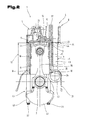
- Fig. 2 the internal combustion engine 1 is shown in a cross section, which runs through the cylinder center of a cylinder 10 and is normal to the axis 2 of the crankshaft 3.
- this section arranged in the crankcase 39 components of the internal combustion engine 1 are shown.
- the bearing shell 40 of a crankshaft bearing, in particular a crankshaft main bearing, by means of a pair of fastening means 23 with the cylinder block 6 and also or simultaneously with the cylinder head unit 5 is screwed.
- the bearing shell 40 is partially of a balancing mass 41 of the crankshaft 3 covered.
- a the lower end of the crankshaft housing 39 forming sump has not been shown for the sake of clarity.
- a recess 42 for the camshaft, and a recess 43 for plunger for valve actuation visible.
- the camshaft and tappets are not shown in this figure.
- the actuation of the valves operates such that the camshaft lying laterally to the cylinders 10 transmits an actuating force to the vertically extending plungers.
- the plungers then in turn pass the appropriate actuating movement to an overhead rocker arm, which then actuates the valves.
- a shoulder surface 44 is formed on the cylinder head unit 5 in the transition region between the head section 8 and the hollow cylinder section 9. This shoulder surface 44 rests against the end face 25 of the cylinder block 6 and can thus absorb the preload force which is built up by the at least one fastening element 23 or transmit it to the cylinder block 6.
- Fig. 3 shows a section through the internal combustion engine 1 in the plane of a pair of fasteners 23.
- a bearing shell 40 of the crankshaft bearing 45 which bearing shell 40 is connected via two helical fasteners 23 with the cylinder block 6, said fasteners 35 subsequently with are bolted to the head portion 8 of the cylinder head unit 5 and anchored in the head portion 8.
- the cylinder block 6 is effectively clamped between at least one bearing shell 40, which completes a crankshaft bearing 45, and the head portion 8 of the cylinder head unit 5.
- the fastening elements 23 are designed as screws which extend from the back of the bearing shell 40 into the cylinder head unit 5.
- the bearing shell 40 and the cylinder block 6 simple through holes, through which the shaft of the fasteners 23 is passed.
- a threaded bore is formed per fastening element 23, into which the fastening elements 23 are screwed.
Landscapes
- Engineering & Computer Science (AREA)
- Chemical & Material Sciences (AREA)
- Combustion & Propulsion (AREA)
- Mechanical Engineering (AREA)
- General Engineering & Computer Science (AREA)
- Cylinder Crankcases Of Internal Combustion Engines (AREA)
Applications Claiming Priority (1)
| Application Number | Priority Date | Filing Date | Title |
|---|---|---|---|
| ATA50486/2013A AT514076B1 (de) | 2013-08-01 | 2013-08-01 | Motorgehäuse einer Brennkraftmaschine sowie damit ausgestattete Brennkraftmaschine |
Publications (1)
| Publication Number | Publication Date |
|---|---|
| EP2832980A1 true EP2832980A1 (de) | 2015-02-04 |
Family
ID=51298555
Family Applications (1)
| Application Number | Title | Priority Date | Filing Date |
|---|---|---|---|
| EP14179464.4A Withdrawn EP2832980A1 (de) | 2013-08-01 | 2014-08-01 | Motorgehäuse einer Brennkraftmaschine sowie damit ausgestattete Brennkraftmaschine |
Country Status (5)
| Country | Link |
|---|---|
| US (1) | US9222434B2 (https=) |
| EP (1) | EP2832980A1 (https=) |
| JP (1) | JP2015031278A (https=) |
| CN (1) | CN104343574A (https=) |
| AT (1) | AT514076B1 (https=) |
Families Citing this family (7)
| Publication number | Priority date | Publication date | Assignee | Title |
|---|---|---|---|---|
| CN106523858B (zh) * | 2016-12-14 | 2017-10-03 | 安徽银盾斯金铝业有限公司 | 一种高强度缓冲式发动机外壳铝型材 |
| US10550754B2 (en) * | 2017-05-15 | 2020-02-04 | Polaris Industries Inc. | Engine |
| FR3066817B1 (fr) * | 2017-05-29 | 2019-08-16 | MCE 5 Development | Dispositif de mesure pour moteur a combustion interne comprenant un detecteur de passage d'une cible et moteur comportant un tel dispositif de mesure |
| US10487778B2 (en) * | 2017-12-01 | 2019-11-26 | GM Global Technology Operations LLC | Composite engine architecture, and method of manufacturing the same |
| JP6896596B2 (ja) * | 2017-12-14 | 2021-06-30 | 株式会社ブリヂストン | タイヤ溝残量管理システム |
| DE102019219378A1 (de) * | 2019-12-11 | 2021-06-17 | Mahle International Gmbh | Zylinderlaufbuchse für eine Brennkraftmaschine |
| CN121273732A (zh) * | 2025-12-08 | 2026-01-06 | 珠海科瑞思科技股份有限公司 | 一种用于热压成型的集成式油缸 |
Citations (7)
| Publication number | Priority date | Publication date | Assignee | Title |
|---|---|---|---|---|
| US4708105A (en) | 1985-12-23 | 1987-11-24 | Ford Motor Company | Chamber construction for internal combustion engine |
| GB2193529A (en) * | 1986-08-05 | 1988-02-10 | Ford Motor Co | Internal combustion engines |
| JPS645063Y2 (https=) * | 1983-10-24 | 1989-02-08 | ||
| DE3823589A1 (de) * | 1988-07-12 | 1990-01-18 | Man Nutzfahrzeuge Ag | Mehrzylinderbrennkraftmaschine mit nassen zylinderlaufbuechsen und einzelzylinderkoepfen |
| DE10208299A1 (de) * | 2002-02-26 | 2003-09-04 | Daimler Chrysler Ag | Brennkraftmaschine |
| WO2004111418A1 (de) | 2003-06-12 | 2004-12-23 | Avl List Gmbh | Brennkraftmaschine |
| GB2425570A (en) | 2005-04-27 | 2006-11-01 | Lotus Car | I.c. engine with cylinder head, cylinder block and manifold formed integrally |
Family Cites Families (17)
| Publication number | Priority date | Publication date | Assignee | Title |
|---|---|---|---|---|
| US3046952A (en) * | 1960-02-11 | 1962-07-31 | Dolza John | Internal combustion engines |
| DE2349173A1 (de) * | 1973-09-29 | 1975-04-03 | Kloeckner Humboldt Deutz Ag | Fluessigkeitsgekuehlte hubkolbenbrennkraftmaschine mit einer zylinder-zylinderkopfeinheit |
| DE3233578C2 (de) * | 1982-09-10 | 1985-09-12 | M.A.N. Maschinenfabrik Augsburg-Nürnberg AG, 8500 Nürnberg | Mehrzylinderbrennkraftmaschine mit nassen Zylinderlaufbüchsen und Einzelzylinderköpfen |
| JPS59126051A (ja) * | 1982-12-29 | 1984-07-20 | Yanmar Diesel Engine Co Ltd | シリンダヘツド |
| US4644911A (en) | 1983-10-07 | 1987-02-24 | Honda Giken Kogyo Kabushiki Kaisha | Cylinder block for internal combustion engine |
| US4699100A (en) * | 1985-12-23 | 1987-10-13 | Ford Motor Company | Chamber construction for internal combustion engine |
| JPS6379453U (https=) * | 1986-11-14 | 1988-05-25 | ||
| JPH0526100A (ja) * | 1991-07-19 | 1993-02-02 | Yanmar Diesel Engine Co Ltd | 水冷式内燃機関 |
| JPH05296103A (ja) * | 1992-04-15 | 1993-11-09 | Nissan Motor Co Ltd | エンジンブロック構造 |
| JPH05321750A (ja) * | 1992-05-19 | 1993-12-07 | Nissan Motor Co Ltd | 内燃機関のライナ構造 |
| JPH09242599A (ja) * | 1996-03-07 | 1997-09-16 | Imazaike Seiko Kk | 2サイクルエンジンの構造 |
| DE19652049C1 (de) * | 1996-12-13 | 1998-07-02 | Hatz Motoren | Brennkraftmaschine und Verfahren zu deren Herstellung |
| EP1722090B1 (en) * | 1998-12-01 | 2013-07-17 | Honda Giken Kogyo Kabushiki Kaisha | Cylinder head structure in multi-cylinder engine |
| DE10112132A1 (de) * | 2001-03-14 | 2002-09-19 | Bayerische Motoren Werke Ag | Zylinderkurbelgehäuse für eine flüssigkeitsgekühlte Brennkraftmaschine |
| JP4404058B2 (ja) * | 2006-02-21 | 2010-01-27 | トヨタ自動車株式会社 | シリンダライナ、シリンダブロック、及びシリンダブロックの製造方法、及びエンジン構造 |
| DE102007042156A1 (de) * | 2007-09-05 | 2009-03-12 | Man Diesel Se | Verbindungsanordnung, insbesondere zum Verspannen eines Zylinderkopfes, mit einem Kurbelgehäuse einer Hubkolbenbrennkraftmaschine |
| DE102009059057A1 (de) * | 2009-12-18 | 2011-06-22 | MAHLE International GmbH, 70376 | Baueinheit aus Zylinderlaufbuchse und Kurbelgehäuse |
-
2013
- 2013-08-01 AT ATA50486/2013A patent/AT514076B1/de active
-
2014
- 2014-05-28 US US14/288,558 patent/US9222434B2/en active Active
- 2014-06-17 JP JP2014124330A patent/JP2015031278A/ja active Pending
- 2014-06-17 CN CN201410270026.8A patent/CN104343574A/zh active Pending
- 2014-08-01 EP EP14179464.4A patent/EP2832980A1/de not_active Withdrawn
Patent Citations (7)
| Publication number | Priority date | Publication date | Assignee | Title |
|---|---|---|---|---|
| JPS645063Y2 (https=) * | 1983-10-24 | 1989-02-08 | ||
| US4708105A (en) | 1985-12-23 | 1987-11-24 | Ford Motor Company | Chamber construction for internal combustion engine |
| GB2193529A (en) * | 1986-08-05 | 1988-02-10 | Ford Motor Co | Internal combustion engines |
| DE3823589A1 (de) * | 1988-07-12 | 1990-01-18 | Man Nutzfahrzeuge Ag | Mehrzylinderbrennkraftmaschine mit nassen zylinderlaufbuechsen und einzelzylinderkoepfen |
| DE10208299A1 (de) * | 2002-02-26 | 2003-09-04 | Daimler Chrysler Ag | Brennkraftmaschine |
| WO2004111418A1 (de) | 2003-06-12 | 2004-12-23 | Avl List Gmbh | Brennkraftmaschine |
| GB2425570A (en) | 2005-04-27 | 2006-11-01 | Lotus Car | I.c. engine with cylinder head, cylinder block and manifold formed integrally |
Also Published As
| Publication number | Publication date |
|---|---|
| US9222434B2 (en) | 2015-12-29 |
| CN104343574A (zh) | 2015-02-11 |
| JP2015031278A (ja) | 2015-02-16 |
| AT514076B1 (de) | 2014-10-15 |
| US20150034038A1 (en) | 2015-02-05 |
| AT514076A4 (de) | 2014-10-15 |
Similar Documents
| Publication | Publication Date | Title |
|---|---|---|
| AT514076B1 (de) | Motorgehäuse einer Brennkraftmaschine sowie damit ausgestattete Brennkraftmaschine | |
| DE3010635C2 (https=) | ||
| DE3233578C2 (de) | Mehrzylinderbrennkraftmaschine mit nassen Zylinderlaufbüchsen und Einzelzylinderköpfen | |
| EP1843029A2 (de) | Gebautes Kurbelgehäuse | |
| EP0695866B1 (de) | Zylinderblock für eine Brennkraftmaschine mit einem Wassermantel aus Aluminium | |
| EP3339617A1 (de) | Zylindergehäuse, verfahren zur herstellung eines zylindergehäuses und giesskern | |
| EP1570167B1 (de) | Gegossenes bauteil für eine brennkraftmaschine | |
| DE2322382A1 (de) | Aufbau von verbrennungsmotoren | |
| DE10325914B4 (de) | Kolben für einen Verbrennungsmotor | |
| DE10304971A1 (de) | Gegossenes Bauteil für eine Brennkraftmaschine | |
| WO2016202330A2 (de) | Verbund, kurbelgehäuse, hubkolben-verbrennungskraftmaschine und verfahren zum herstellen einer hubkolben-verbrennungskraftmaschine | |
| EP0883740A1 (de) | Brennkraftmaschine und verfahren zu deren herstellung | |
| DE102004057558A1 (de) | Kolben für einen Verbrennungsmotor | |
| DE10235910B4 (de) | Verbund von Zylinderlaufbuchsen aus Leichtmetall-Legierung, Verfahren zum Herstellen eines Verbundes und Verfahren zum Eingießen eines Verbundes | |
| EP0771944B1 (de) | Gehäuse für eine Hubkolben-Brennkraftmaschine | |
| DE112004002493T5 (de) | Vereinfachte Motorarchitektur und Motorbaugruppe | |
| EP1336746A1 (de) | Zylinderblock und Druckgussverfahren zu dessen Herstellung | |
| DE19955809B4 (de) | Kolben eines Verbrennungsmotors | |
| DE10350500B4 (de) | Verfahren zur Vergrößerung von Motorzylinderbohrungen | |
| AT519298A2 (de) | Pleuelstange mit Verstellmechanismus zwischen Pleuelfuß und Kolbenstange | |
| DE3604667A1 (de) | Gegossener zylinderkopf fuer eine mehrzylindrige reihen-brennkraftmaschine | |
| DE10221675C5 (de) | Zylindergehäuse | |
| AT519303B1 (de) | Pleuelstange mit Stufenkolben | |
| DE3931678C2 (de) | Zylinderblock für eine wassergekühlte Mehrzylinder-Brennkraftmaschine | |
| AT525164B1 (de) | Brennkraftmaschine mit einem zylinderblock |
Legal Events
| Date | Code | Title | Description |
|---|---|---|---|
| 17P | Request for examination filed |
Effective date: 20140801 |
|
| AK | Designated contracting states |
Kind code of ref document: A1 Designated state(s): AL AT BE BG CH CY CZ DE DK EE ES FI FR GB GR HR HU IE IS IT LI LT LU LV MC MK MT NL NO PL PT RO RS SE SI SK SM TR |
|
| AX | Request for extension of the european patent |
Extension state: BA ME |
|
| PUAI | Public reference made under article 153(3) epc to a published international application that has entered the european phase |
Free format text: ORIGINAL CODE: 0009012 |
|
| R17P | Request for examination filed (corrected) |
Effective date: 20150703 |
|
| RBV | Designated contracting states (corrected) |
Designated state(s): AL AT BE BG CH CY CZ DE DK EE ES FI FR GB GR HR HU IE IS IT LI LT LU LV MC MK MT NL NO PL PT RO RS SE SI SK SM TR |
|
| 17Q | First examination report despatched |
Effective date: 20180103 |
|
| RAP1 | Party data changed (applicant data changed or rights of an application transferred) |
Owner name: STEYR MOTORS GMBH |
|
| RIC1 | Information provided on ipc code assigned before grant |
Ipc: F02F 7/00 20060101ALI20190219BHEP Ipc: F02F 1/00 20060101AFI20190219BHEP |
|
| STAA | Information on the status of an ep patent application or granted ep patent |
Free format text: STATUS: THE APPLICATION IS DEEMED TO BE WITHDRAWN |
|
| 18D | Application deemed to be withdrawn |
Effective date: 20190808 |