EP2832845A1 - Trieur de cellules par imagerie - Google Patents
Trieur de cellules par imagerie Download PDFInfo
- Publication number
- EP2832845A1 EP2832845A1 EP13769361.0A EP13769361A EP2832845A1 EP 2832845 A1 EP2832845 A1 EP 2832845A1 EP 13769361 A EP13769361 A EP 13769361A EP 2832845 A1 EP2832845 A1 EP 2832845A1
- Authority
- EP
- European Patent Office
- Prior art keywords
- cell
- flow path
- image
- cells
- target cell
- Prior art date
- Legal status (The legal status is an assumption and is not a legal conclusion. Google has not performed a legal analysis and makes no representation as to the accuracy of the status listed.)
- Withdrawn
Links
- 238000003384 imaging method Methods 0.000 title description 4
- 210000004027 cell Anatomy 0.000 claims description 1234
- 239000007788 liquid Substances 0.000 claims description 210
- 239000012488 sample solution Substances 0.000 claims description 149
- 230000007246 mechanism Effects 0.000 claims description 129
- 238000011084 recovery Methods 0.000 claims description 105
- 230000003287 optical effect Effects 0.000 claims description 101
- 238000004458 analytical method Methods 0.000 claims description 97
- 206010028980 Neoplasm Diseases 0.000 claims description 87
- 201000011510 cancer Diseases 0.000 claims description 86
- 238000011144 upstream manufacturing Methods 0.000 claims description 72
- 238000000034 method Methods 0.000 claims description 65
- 239000008280 blood Substances 0.000 claims description 53
- 239000002699 waste material Substances 0.000 claims description 53
- 210000004369 blood Anatomy 0.000 claims description 52
- 239000000243 solution Substances 0.000 claims description 44
- 238000001514 detection method Methods 0.000 claims description 37
- 238000002073 fluorescence micrograph Methods 0.000 claims description 36
- XLYOFNOQVPJJNP-UHFFFAOYSA-N water Substances O XLYOFNOQVPJJNP-UHFFFAOYSA-N 0.000 claims description 31
- 239000007850 fluorescent dye Substances 0.000 claims description 23
- 229910052751 metal Inorganic materials 0.000 claims description 22
- 239000002184 metal Substances 0.000 claims description 22
- 239000007853 buffer solution Substances 0.000 claims description 21
- 239000013307 optical fiber Substances 0.000 claims description 21
- 108090000623 proteins and genes Proteins 0.000 claims description 19
- 210000005088 multinucleated cell Anatomy 0.000 claims description 17
- 238000010252 digital analysis Methods 0.000 claims description 16
- 230000005484 gravity Effects 0.000 claims description 16
- 238000010191 image analysis Methods 0.000 claims description 16
- 238000001215 fluorescent labelling Methods 0.000 claims description 13
- 210000004413 cardiac myocyte Anatomy 0.000 claims description 11
- 238000009826 distribution Methods 0.000 claims description 11
- 238000012360 testing method Methods 0.000 claims description 10
- 239000000126 substance Substances 0.000 claims description 9
- 238000004891 communication Methods 0.000 claims description 8
- 239000012530 fluid Substances 0.000 claims description 8
- 150000007523 nucleic acids Chemical group 0.000 claims description 8
- 239000008279 sol Substances 0.000 claims description 8
- 238000001228 spectrum Methods 0.000 claims description 5
- 239000000090 biomarker Substances 0.000 claims description 4
- 101150084967 EPCAM gene Proteins 0.000 claims description 3
- 101710113436 GTPase KRas Proteins 0.000 claims description 3
- 108010076876 Keratins Proteins 0.000 claims description 3
- 102000011782 Keratins Human genes 0.000 claims description 3
- 108091028043 Nucleic acid sequence Proteins 0.000 claims description 3
- 230000005540 biological transmission Effects 0.000 claims description 2
- 230000009467 reduction Effects 0.000 claims description 2
- 230000003746 surface roughness Effects 0.000 claims description 2
- 238000000746 purification Methods 0.000 abstract description 46
- 239000000523 sample Substances 0.000 description 134
- 238000006243 chemical reaction Methods 0.000 description 69
- 230000005284 excitation Effects 0.000 description 65
- 238000000926 separation method Methods 0.000 description 63
- 239000002245 particle Substances 0.000 description 61
- 239000000499 gel Substances 0.000 description 46
- 238000005259 measurement Methods 0.000 description 32
- 238000012546 transfer Methods 0.000 description 32
- 238000010186 staining Methods 0.000 description 25
- 238000005516 engineering process Methods 0.000 description 24
- 238000001917 fluorescence detection Methods 0.000 description 23
- 238000010195 expression analysis Methods 0.000 description 18
- 230000005684 electric field Effects 0.000 description 17
- 230000008569 process Effects 0.000 description 16
- 230000005855 radiation Effects 0.000 description 14
- 239000003795 chemical substances by application Substances 0.000 description 13
- 210000001519 tissue Anatomy 0.000 description 13
- 238000005304 joining Methods 0.000 description 12
- 239000000758 substrate Substances 0.000 description 11
- 230000008859 change Effects 0.000 description 10
- 239000000203 mixture Substances 0.000 description 9
- 210000000130 stem cell Anatomy 0.000 description 9
- 238000005406 washing Methods 0.000 description 9
- 239000007864 aqueous solution Substances 0.000 description 8
- 239000003153 chemical reaction reagent Substances 0.000 description 8
- 239000003814 drug Substances 0.000 description 8
- 239000000872 buffer Substances 0.000 description 7
- 238000011109 contamination Methods 0.000 description 7
- 230000003247 decreasing effect Effects 0.000 description 7
- 238000000227 grinding Methods 0.000 description 7
- 238000002372 labelling Methods 0.000 description 7
- 239000010409 thin film Substances 0.000 description 7
- 241000193738 Bacillus anthracis Species 0.000 description 6
- 108020004414 DNA Proteins 0.000 description 6
- 229940065181 bacillus anthracis Drugs 0.000 description 6
- 239000011521 glass Substances 0.000 description 6
- 208000005443 Circulating Neoplastic Cells Diseases 0.000 description 5
- 206010027476 Metastases Diseases 0.000 description 5
- 230000001154 acute effect Effects 0.000 description 5
- 239000003792 electrolyte Substances 0.000 description 5
- 230000009401 metastasis Effects 0.000 description 5
- 108020004707 nucleic acids Proteins 0.000 description 5
- 102000039446 nucleic acids Human genes 0.000 description 5
- 239000012521 purified sample Substances 0.000 description 5
- FWBHETKCLVMNFS-UHFFFAOYSA-N 4',6-Diamino-2-phenylindol Chemical compound C1=CC(C(=N)N)=CC=C1C1=CC2=CC=C(C(N)=N)C=C2N1 FWBHETKCLVMNFS-UHFFFAOYSA-N 0.000 description 4
- 241000894006 Bacteria Species 0.000 description 4
- 210000004102 animal cell Anatomy 0.000 description 4
- 230000001093 anti-cancer Effects 0.000 description 4
- 210000000601 blood cell Anatomy 0.000 description 4
- 230000005859 cell recognition Effects 0.000 description 4
- 230000007423 decrease Effects 0.000 description 4
- 239000003550 marker Substances 0.000 description 4
- 239000000463 material Substances 0.000 description 4
- 210000000056 organ Anatomy 0.000 description 4
- 238000012545 processing Methods 0.000 description 4
- 230000001640 apoptogenic effect Effects 0.000 description 3
- 230000006907 apoptotic process Effects 0.000 description 3
- 230000002238 attenuated effect Effects 0.000 description 3
- 230000008901 benefit Effects 0.000 description 3
- 230000008033 biological extinction Effects 0.000 description 3
- 230000017531 blood circulation Effects 0.000 description 3
- 230000032823 cell division Effects 0.000 description 3
- 238000012258 culturing Methods 0.000 description 3
- 239000003599 detergent Substances 0.000 description 3
- 238000003745 diagnosis Methods 0.000 description 3
- 230000000694 effects Effects 0.000 description 3
- 238000007710 freezing Methods 0.000 description 3
- 230000008014 freezing Effects 0.000 description 3
- 238000007689 inspection Methods 0.000 description 3
- 239000004033 plastic Substances 0.000 description 3
- 229920003023 plastic Polymers 0.000 description 3
- 230000001360 synchronised effect Effects 0.000 description 3
- 239000000439 tumor marker Substances 0.000 description 3
- 108090000790 Enzymes Proteins 0.000 description 2
- 102000004190 Enzymes Human genes 0.000 description 2
- CSNNHWWHGAXBCP-UHFFFAOYSA-L Magnesium sulfate Chemical compound [Mg+2].[O-][S+2]([O-])([O-])[O-] CSNNHWWHGAXBCP-UHFFFAOYSA-L 0.000 description 2
- PXHVJJICTQNCMI-UHFFFAOYSA-N Nickel Chemical compound [Ni] PXHVJJICTQNCMI-UHFFFAOYSA-N 0.000 description 2
- 101710160107 Outer membrane protein A Proteins 0.000 description 2
- 241000950638 Symphysodon discus Species 0.000 description 2
- 238000010521 absorption reaction Methods 0.000 description 2
- 239000011543 agarose gel Substances 0.000 description 2
- 238000003491 array Methods 0.000 description 2
- 230000000712 assembly Effects 0.000 description 2
- 238000000429 assembly Methods 0.000 description 2
- 210000001054 cardiac fibroblast Anatomy 0.000 description 2
- 238000002591 computed tomography Methods 0.000 description 2
- 210000000805 cytoplasm Anatomy 0.000 description 2
- SUYVUBYJARFZHO-RRKCRQDMSA-N dATP Chemical compound C1=NC=2C(N)=NC=NC=2N1[C@H]1C[C@H](O)[C@@H](COP(O)(=O)OP(O)(=O)OP(O)(O)=O)O1 SUYVUBYJARFZHO-RRKCRQDMSA-N 0.000 description 2
- SUYVUBYJARFZHO-UHFFFAOYSA-N dATP Natural products C1=NC=2C(N)=NC=NC=2N1C1CC(O)C(COP(O)(=O)OP(O)(=O)OP(O)(O)=O)O1 SUYVUBYJARFZHO-UHFFFAOYSA-N 0.000 description 2
- RGWHQCVHVJXOKC-SHYZEUOFSA-J dCTP(4-) Chemical compound O=C1N=C(N)C=CN1[C@@H]1O[C@H](COP([O-])(=O)OP([O-])(=O)OP([O-])([O-])=O)[C@@H](O)C1 RGWHQCVHVJXOKC-SHYZEUOFSA-J 0.000 description 2
- HAAZLUGHYHWQIW-KVQBGUIXSA-N dGTP Chemical compound C1=NC=2C(=O)NC(N)=NC=2N1[C@H]1C[C@H](O)[C@@H](COP(O)(=O)OP(O)(=O)OP(O)(O)=O)O1 HAAZLUGHYHWQIW-KVQBGUIXSA-N 0.000 description 2
- NHVNXKFIZYSCEB-XLPZGREQSA-N dTTP Chemical compound O=C1NC(=O)C(C)=CN1[C@@H]1O[C@H](COP(O)(=O)OP(O)(=O)OP(O)(O)=O)[C@@H](O)C1 NHVNXKFIZYSCEB-XLPZGREQSA-N 0.000 description 2
- 239000000975 dye Substances 0.000 description 2
- 238000011156 evaluation Methods 0.000 description 2
- 239000000835 fiber Substances 0.000 description 2
- 230000002068 genetic effect Effects 0.000 description 2
- 210000001990 heterocyst Anatomy 0.000 description 2
- 238000002347 injection Methods 0.000 description 2
- 239000007924 injection Substances 0.000 description 2
- HOQADATXFBOEGG-UHFFFAOYSA-N isofenphos Chemical compound CCOP(=S)(NC(C)C)OC1=CC=CC=C1C(=O)OC(C)C HOQADATXFBOEGG-UHFFFAOYSA-N 0.000 description 2
- 239000005001 laminate film Substances 0.000 description 2
- 238000002595 magnetic resonance imaging Methods 0.000 description 2
- INAAIJLSXJJHOZ-UHFFFAOYSA-N pibenzimol Chemical compound C1CN(C)CCN1C1=CC=C(N=C(N2)C=3C=C4NC(=NC4=CC=3)C=3C=CC(O)=CC=3)C2=C1 INAAIJLSXJJHOZ-UHFFFAOYSA-N 0.000 description 2
- BASFCYQUMIYNBI-UHFFFAOYSA-N platinum Chemical compound [Pt] BASFCYQUMIYNBI-UHFFFAOYSA-N 0.000 description 2
- 229920003229 poly(methyl methacrylate) Polymers 0.000 description 2
- 239000004926 polymethyl methacrylate Substances 0.000 description 2
- 238000007781 pre-processing Methods 0.000 description 2
- 238000003825 pressing Methods 0.000 description 2
- 238000003672 processing method Methods 0.000 description 2
- 230000001172 regenerating effect Effects 0.000 description 2
- 230000004044 response Effects 0.000 description 2
- 238000005070 sampling Methods 0.000 description 2
- 239000004065 semiconductor Substances 0.000 description 2
- 210000004881 tumor cell Anatomy 0.000 description 2
- 230000000007 visual effect Effects 0.000 description 2
- 229910052724 xenon Inorganic materials 0.000 description 2
- FHNFHKCVQCLJFQ-UHFFFAOYSA-N xenon atom Chemical compound [Xe] FHNFHKCVQCLJFQ-UHFFFAOYSA-N 0.000 description 2
- 239000004925 Acrylic resin Substances 0.000 description 1
- 229920000178 Acrylic resin Polymers 0.000 description 1
- QGZKDVFQNNGYKY-UHFFFAOYSA-N Ammonia Chemical compound N QGZKDVFQNNGYKY-UHFFFAOYSA-N 0.000 description 1
- 108091023037 Aptamer Proteins 0.000 description 1
- 206010005003 Bladder cancer Diseases 0.000 description 1
- 108091003079 Bovine Serum Albumin Proteins 0.000 description 1
- 108020004635 Complementary DNA Proteins 0.000 description 1
- 230000004544 DNA amplification Effects 0.000 description 1
- 102000016928 DNA-directed DNA polymerase Human genes 0.000 description 1
- 108010014303 DNA-directed DNA polymerase Proteins 0.000 description 1
- 206010064571 Gene mutation Diseases 0.000 description 1
- FYYHWMGAXLPEAU-UHFFFAOYSA-N Magnesium Chemical compound [Mg] FYYHWMGAXLPEAU-UHFFFAOYSA-N 0.000 description 1
- 241001465754 Metazoa Species 0.000 description 1
- 238000012408 PCR amplification Methods 0.000 description 1
- 238000010222 PCR analysis Methods 0.000 description 1
- 239000004696 Poly ether ether ketone Substances 0.000 description 1
- 239000004793 Polystyrene Substances 0.000 description 1
- CGNLCCVKSWNSDG-UHFFFAOYSA-N SYBR Green I Chemical compound CN(C)CCCN(CCC)C1=CC(C=C2N(C3=CC=CC=C3S2)C)=C2C=CC=CC2=[N+]1C1=CC=CC=C1 CGNLCCVKSWNSDG-UHFFFAOYSA-N 0.000 description 1
- 206010046431 Urethral cancer Diseases 0.000 description 1
- 206010046458 Urethral neoplasms Diseases 0.000 description 1
- 208000007097 Urinary Bladder Neoplasms Diseases 0.000 description 1
- 229910052782 aluminium Inorganic materials 0.000 description 1
- XAGFODPZIPBFFR-UHFFFAOYSA-N aluminium Chemical compound [Al] XAGFODPZIPBFFR-UHFFFAOYSA-N 0.000 description 1
- 238000000149 argon plasma sintering Methods 0.000 description 1
- JUPQTSLXMOCDHR-UHFFFAOYSA-N benzene-1,4-diol;bis(4-fluorophenyl)methanone Chemical compound OC1=CC=C(O)C=C1.C1=CC(F)=CC=C1C(=O)C1=CC=C(F)C=C1 JUPQTSLXMOCDHR-UHFFFAOYSA-N 0.000 description 1
- 238000001574 biopsy Methods 0.000 description 1
- 230000000903 blocking effect Effects 0.000 description 1
- 210000004204 blood vessel Anatomy 0.000 description 1
- 238000007664 blowing Methods 0.000 description 1
- 238000009835 boiling Methods 0.000 description 1
- 238000010804 cDNA synthesis Methods 0.000 description 1
- 208000035269 cancer or benign tumor Diseases 0.000 description 1
- 239000002771 cell marker Substances 0.000 description 1
- 210000003850 cellular structure Anatomy 0.000 description 1
- 238000000701 chemical imaging Methods 0.000 description 1
- 239000007795 chemical reaction product Substances 0.000 description 1
- 239000003086 colorant Substances 0.000 description 1
- 239000002299 complementary DNA Substances 0.000 description 1
- 238000007796 conventional method Methods 0.000 description 1
- 238000012864 cross contamination Methods 0.000 description 1
- 230000003412 degenerative effect Effects 0.000 description 1
- 239000005549 deoxyribonucleoside Substances 0.000 description 1
- 238000011161 development Methods 0.000 description 1
- 230000004069 differentiation Effects 0.000 description 1
- 239000003085 diluting agent Substances 0.000 description 1
- 229940079593 drug Drugs 0.000 description 1
- 108010048367 enhanced green fluorescent protein Proteins 0.000 description 1
- 210000003743 erythrocyte Anatomy 0.000 description 1
- 239000012091 fetal bovine serum Substances 0.000 description 1
- 210000002950 fibroblast Anatomy 0.000 description 1
- 238000010304 firing Methods 0.000 description 1
- 238000000684 flow cytometry Methods 0.000 description 1
- 238000012757 fluorescence staining Methods 0.000 description 1
- -1 for example Substances 0.000 description 1
- PCHJSUWPFVWCPO-UHFFFAOYSA-N gold Chemical compound [Au] PCHJSUWPFVWCPO-UHFFFAOYSA-N 0.000 description 1
- 229910052737 gold Inorganic materials 0.000 description 1
- 239000010931 gold Substances 0.000 description 1
- 238000009396 hybridization Methods 0.000 description 1
- 230000006872 improvement Effects 0.000 description 1
- 238000001746 injection moulding Methods 0.000 description 1
- 210000001365 lymphatic vessel Anatomy 0.000 description 1
- 229910052749 magnesium Inorganic materials 0.000 description 1
- 239000011777 magnesium Substances 0.000 description 1
- 229910052943 magnesium sulfate Inorganic materials 0.000 description 1
- 235000019341 magnesium sulphate Nutrition 0.000 description 1
- 230000003211 malignant effect Effects 0.000 description 1
- QSHDDOUJBYECFT-UHFFFAOYSA-N mercury Chemical compound [Hg] QSHDDOUJBYECFT-UHFFFAOYSA-N 0.000 description 1
- 229910052753 mercury Inorganic materials 0.000 description 1
- 108020004999 messenger RNA Proteins 0.000 description 1
- 230000001394 metastastic effect Effects 0.000 description 1
- 206010061289 metastatic neoplasm Diseases 0.000 description 1
- 238000012544 monitoring process Methods 0.000 description 1
- 230000000877 morphologic effect Effects 0.000 description 1
- 229910052759 nickel Inorganic materials 0.000 description 1
- 239000000101 novel biomarker Substances 0.000 description 1
- 239000002773 nucleotide Substances 0.000 description 1
- 125000003729 nucleotide group Chemical group 0.000 description 1
- 229920001778 nylon Polymers 0.000 description 1
- 210000005259 peripheral blood Anatomy 0.000 description 1
- 239000011886 peripheral blood Substances 0.000 description 1
- 150000002978 peroxides Chemical class 0.000 description 1
- 229910052697 platinum Inorganic materials 0.000 description 1
- 239000004417 polycarbonate Substances 0.000 description 1
- 229920000515 polycarbonate Polymers 0.000 description 1
- 229920002530 polyetherether ketone Polymers 0.000 description 1
- 229920000642 polymer Polymers 0.000 description 1
- 238000003752 polymerase chain reaction Methods 0.000 description 1
- 229920002223 polystyrene Polymers 0.000 description 1
- 238000001556 precipitation Methods 0.000 description 1
- 238000002360 preparation method Methods 0.000 description 1
- 230000002265 prevention Effects 0.000 description 1
- 239000011535 reaction buffer Substances 0.000 description 1
- 238000001454 recorded image Methods 0.000 description 1
- 238000010992 reflux Methods 0.000 description 1
- 238000010839 reverse transcription Methods 0.000 description 1
- 230000002441 reversible effect Effects 0.000 description 1
- 150000003839 salts Chemical class 0.000 description 1
- 238000004062 sedimentation Methods 0.000 description 1
- 230000035945 sensitivity Effects 0.000 description 1
- 229920002545 silicone oil Polymers 0.000 description 1
- 238000003756 stirring Methods 0.000 description 1
- 235000000346 sugar Nutrition 0.000 description 1
- 150000008163 sugars Chemical class 0.000 description 1
- 238000010897 surface acoustic wave method Methods 0.000 description 1
- 230000002123 temporal effect Effects 0.000 description 1
- JGVWCANSWKRBCS-UHFFFAOYSA-N tetramethylrhodamine thiocyanate Chemical compound [Cl-].C=12C=CC(N(C)C)=CC2=[O+]C2=CC(N(C)C)=CC=C2C=1C1=CC=C(SC#N)C=C1C(O)=O JGVWCANSWKRBCS-UHFFFAOYSA-N 0.000 description 1
- MPLHNVLQVRSVEE-UHFFFAOYSA-N texas red Chemical compound [O-]S(=O)(=O)C1=CC(S(Cl)(=O)=O)=CC=C1C(C1=CC=2CCCN3CCCC(C=23)=C1O1)=C2C1=C(CCC1)C3=[N+]1CCCC3=C2 MPLHNVLQVRSVEE-UHFFFAOYSA-N 0.000 description 1
- 238000005382 thermal cycling Methods 0.000 description 1
- 239000001226 triphosphate Substances 0.000 description 1
- 235000011178 triphosphate Nutrition 0.000 description 1
- 125000002264 triphosphate group Chemical class [H]OP(=O)(O[H])OP(=O)(O[H])OP(=O)(O[H])O* 0.000 description 1
- 201000000360 urethra cancer Diseases 0.000 description 1
- 201000005112 urinary bladder cancer Diseases 0.000 description 1
- 210000002700 urine Anatomy 0.000 description 1
Images


Classifications
-
- G—PHYSICS
- G01—MEASURING; TESTING
- G01N—INVESTIGATING OR ANALYSING MATERIALS BY DETERMINING THEIR CHEMICAL OR PHYSICAL PROPERTIES
- G01N33/00—Investigating or analysing materials by specific methods not covered by groups G01N1/00 - G01N31/00
- G01N33/48—Biological material, e.g. blood, urine; Haemocytometers
- G01N33/50—Chemical analysis of biological material, e.g. blood, urine; Testing involving biospecific ligand binding methods; Immunological testing
- G01N33/53—Immunoassay; Biospecific binding assay; Materials therefor
- G01N33/574—Immunoassay; Biospecific binding assay; Materials therefor for cancer
- G01N33/57484—Immunoassay; Biospecific binding assay; Materials therefor for cancer involving compounds serving as markers for tumor, cancer, neoplasia, e.g. cellular determinants, receptors, heat shock/stress proteins, A-protein, oligosaccharides, metabolites
- G01N33/57496—Immunoassay; Biospecific binding assay; Materials therefor for cancer involving compounds serving as markers for tumor, cancer, neoplasia, e.g. cellular determinants, receptors, heat shock/stress proteins, A-protein, oligosaccharides, metabolites involving intracellular compounds
-
- C—CHEMISTRY; METALLURGY
- C12—BIOCHEMISTRY; BEER; SPIRITS; WINE; VINEGAR; MICROBIOLOGY; ENZYMOLOGY; MUTATION OR GENETIC ENGINEERING
- C12M—APPARATUS FOR ENZYMOLOGY OR MICROBIOLOGY; APPARATUS FOR CULTURING MICROORGANISMS FOR PRODUCING BIOMASS, FOR GROWING CELLS OR FOR OBTAINING FERMENTATION OR METABOLIC PRODUCTS, i.e. BIOREACTORS OR FERMENTERS
- C12M47/00—Means for after-treatment of the produced biomass or of the fermentation or metabolic products, e.g. storage of biomass
- C12M47/04—Cell isolation or sorting
-
- G01N15/1433—
-
- G—PHYSICS
- G01—MEASURING; TESTING
- G01N—INVESTIGATING OR ANALYSING MATERIALS BY DETERMINING THEIR CHEMICAL OR PHYSICAL PROPERTIES
- G01N15/00—Investigating characteristics of particles; Investigating permeability, pore-volume, or surface-area of porous materials
- G01N15/10—Investigating individual particles
- G01N15/14—Electro-optical investigation, e.g. flow cytometers
- G01N15/1434—Electro-optical investigation, e.g. flow cytometers using an analyser being characterised by its optical arrangement
-
- G—PHYSICS
- G01—MEASURING; TESTING
- G01N—INVESTIGATING OR ANALYSING MATERIALS BY DETERMINING THEIR CHEMICAL OR PHYSICAL PROPERTIES
- G01N15/00—Investigating characteristics of particles; Investigating permeability, pore-volume, or surface-area of porous materials
- G01N15/10—Investigating individual particles
- G01N15/14—Electro-optical investigation, e.g. flow cytometers
- G01N15/1456—Electro-optical investigation, e.g. flow cytometers without spatial resolution of the texture or inner structure of the particle, e.g. processing of pulse signals
- G01N15/1459—Electro-optical investigation, e.g. flow cytometers without spatial resolution of the texture or inner structure of the particle, e.g. processing of pulse signals the analysis being performed on a sample stream
-
- G—PHYSICS
- G01—MEASURING; TESTING
- G01N—INVESTIGATING OR ANALYSING MATERIALS BY DETERMINING THEIR CHEMICAL OR PHYSICAL PROPERTIES
- G01N15/00—Investigating characteristics of particles; Investigating permeability, pore-volume, or surface-area of porous materials
- G01N15/10—Investigating individual particles
- G01N15/14—Electro-optical investigation, e.g. flow cytometers
- G01N15/1468—Electro-optical investigation, e.g. flow cytometers with spatial resolution of the texture or inner structure of the particle
- G01N15/147—Electro-optical investigation, e.g. flow cytometers with spatial resolution of the texture or inner structure of the particle the analysis being performed on a sample stream
-
- G—PHYSICS
- G01—MEASURING; TESTING
- G01N—INVESTIGATING OR ANALYSING MATERIALS BY DETERMINING THEIR CHEMICAL OR PHYSICAL PROPERTIES
- G01N21/00—Investigating or analysing materials by the use of optical means, i.e. using sub-millimetre waves, infrared, visible or ultraviolet light
- G01N21/62—Systems in which the material investigated is excited whereby it emits light or causes a change in wavelength of the incident light
- G01N21/63—Systems in which the material investigated is excited whereby it emits light or causes a change in wavelength of the incident light optically excited
- G01N21/64—Fluorescence; Phosphorescence
- G01N21/645—Specially adapted constructive features of fluorimeters
- G01N21/6456—Spatial resolved fluorescence measurements; Imaging
- G01N21/6458—Fluorescence microscopy
-
- G—PHYSICS
- G01—MEASURING; TESTING
- G01N—INVESTIGATING OR ANALYSING MATERIALS BY DETERMINING THEIR CHEMICAL OR PHYSICAL PROPERTIES
- G01N21/00—Investigating or analysing materials by the use of optical means, i.e. using sub-millimetre waves, infrared, visible or ultraviolet light
- G01N21/62—Systems in which the material investigated is excited whereby it emits light or causes a change in wavelength of the incident light
- G01N21/63—Systems in which the material investigated is excited whereby it emits light or causes a change in wavelength of the incident light optically excited
- G01N21/64—Fluorescence; Phosphorescence
- G01N21/6486—Measuring fluorescence of biological material, e.g. DNA, RNA, cells
-
- G—PHYSICS
- G01—MEASURING; TESTING
- G01N—INVESTIGATING OR ANALYSING MATERIALS BY DETERMINING THEIR CHEMICAL OR PHYSICAL PROPERTIES
- G01N33/00—Investigating or analysing materials by specific methods not covered by groups G01N1/00 - G01N31/00
- G01N33/48—Biological material, e.g. blood, urine; Haemocytometers
- G01N33/50—Chemical analysis of biological material, e.g. blood, urine; Testing involving biospecific ligand binding methods; Immunological testing
- G01N33/53—Immunoassay; Biospecific binding assay; Materials therefor
- G01N33/574—Immunoassay; Biospecific binding assay; Materials therefor for cancer
-
- G—PHYSICS
- G06—COMPUTING; CALCULATING OR COUNTING
- G06T—IMAGE DATA PROCESSING OR GENERATION, IN GENERAL
- G06T7/00—Image analysis
- G06T7/0002—Inspection of images, e.g. flaw detection
- G06T7/0012—Biomedical image inspection
-
- G—PHYSICS
- G06—COMPUTING; CALCULATING OR COUNTING
- G06V—IMAGE OR VIDEO RECOGNITION OR UNDERSTANDING
- G06V20/00—Scenes; Scene-specific elements
- G06V20/60—Type of objects
- G06V20/69—Microscopic objects, e.g. biological cells or cellular parts
- G06V20/698—Matching; Classification
-
- B—PERFORMING OPERATIONS; TRANSPORTING
- B01—PHYSICAL OR CHEMICAL PROCESSES OR APPARATUS IN GENERAL
- B01L—CHEMICAL OR PHYSICAL LABORATORY APPARATUS FOR GENERAL USE
- B01L3/00—Containers or dishes for laboratory use, e.g. laboratory glassware; Droppers
- B01L3/50—Containers for the purpose of retaining a material to be analysed, e.g. test tubes
- B01L3/502—Containers for the purpose of retaining a material to be analysed, e.g. test tubes with fluid transport, e.g. in multi-compartment structures
- B01L3/5027—Containers for the purpose of retaining a material to be analysed, e.g. test tubes with fluid transport, e.g. in multi-compartment structures by integrated microfluidic structures, i.e. dimensions of channels and chambers are such that surface tension forces are important, e.g. lab-on-a-chip
- B01L3/502761—Containers for the purpose of retaining a material to be analysed, e.g. test tubes with fluid transport, e.g. in multi-compartment structures by integrated microfluidic structures, i.e. dimensions of channels and chambers are such that surface tension forces are important, e.g. lab-on-a-chip specially adapted for handling suspended solids or molecules independently from the bulk fluid flow, e.g. for trapping or sorting beads, for physically stretching molecules
-
- G01N15/149—
-
- G01N2015/135—
-
- G—PHYSICS
- G01—MEASURING; TESTING
- G01N—INVESTIGATING OR ANALYSING MATERIALS BY DETERMINING THEIR CHEMICAL OR PHYSICAL PROPERTIES
- G01N15/00—Investigating characteristics of particles; Investigating permeability, pore-volume, or surface-area of porous materials
- G01N15/10—Investigating individual particles
- G01N15/14—Electro-optical investigation, e.g. flow cytometers
- G01N2015/1497—Particle shape
-
- G—PHYSICS
- G06—COMPUTING; CALCULATING OR COUNTING
- G06T—IMAGE DATA PROCESSING OR GENERATION, IN GENERAL
- G06T2207/00—Indexing scheme for image analysis or image enhancement
- G06T2207/10—Image acquisition modality
- G06T2207/10056—Microscopic image
-
- G—PHYSICS
- G06—COMPUTING; CALCULATING OR COUNTING
- G06T—IMAGE DATA PROCESSING OR GENERATION, IN GENERAL
- G06T2207/00—Indexing scheme for image analysis or image enhancement
- G06T2207/10—Image acquisition modality
- G06T2207/10064—Fluorescence image
-
- G—PHYSICS
- G06—COMPUTING; CALCULATING OR COUNTING
- G06T—IMAGE DATA PROCESSING OR GENERATION, IN GENERAL
- G06T2207/00—Indexing scheme for image analysis or image enhancement
- G06T2207/30—Subject of image; Context of image processing
- G06T2207/30004—Biomedical image processing
- G06T2207/30024—Cell structures in vitro; Tissue sections in vitro
-
- G—PHYSICS
- G06—COMPUTING; CALCULATING OR COUNTING
- G06T—IMAGE DATA PROCESSING OR GENERATION, IN GENERAL
- G06T2207/00—Indexing scheme for image analysis or image enhancement
- G06T2207/30—Subject of image; Context of image processing
- G06T2207/30004—Biomedical image processing
- G06T2207/30101—Blood vessel; Artery; Vein; Vascular
Definitions
- the present invention relates to a cell recovery device.
- each of the various cells plays its own role to keep the function thereof in a coordinated manner.
- a part of the tissue becomes a cancerous (herein, the term “cancer” encompasses cancers and tumors)
- the neoplasm of that part becomes different from the area around that part.
- Such a cancer area and a normal tissue area in close proximity to the cancer area are not necessarily separated along a border, and the area around the cancer area is influenced in some way. Therefore, in order to analyze the function of an organ tissue, a small number of cells present in a narrow area needs to be separated in a short time, as simply as possible, and with minimum loss.
- cells are distinguished as follows.
- a cell sorter for example, is available, which is operated as follows. After cells are treated with fluorescence staining, each cell is isolated and caused to be contained in a charged droplet, and the droplets are dripped one by one. While the droplets are falling down, a high electric field is applied in an optional direction in a planar direction normal to the falling direction, based on whether or not there is fluorescence in the cell in the droplet and the magnitude of light scattering, so that the falling direction is controlled. Thus, the cells are fractionated into a plurality of containers located below and recovered. (Non-patent Document 1: Kamarck, M. E., Methods Enzymol., Vol. 151, pp. 150-165 (1987 ))
- Patent Document 1 Japanese Laid-Open Patent Publication No. 2003-107099
- Patent Document 2 Japanese Laid-Open Patent Publication No. 2004-85323
- Patent Document 3 WO2004/101731 .
- These cell sorters are sufficiently practical on a laboratory level. For general-purpose uses, however, new technological development is necessary on the liquid transfer method, recovery method, and pre-processing including sample preparation.
- CTCs circulating tumor cells
- an anticancer medicine effectively destroying the cells can be selected. If a technology of monitoring CTCs flowing in the blood is realized, such a technology can measure, quantitatively, the presence of malignant tumor cells flowing in the blood, which cause cancer metastasis, evaluate the effect of the administered anticancer medicine quantitatively and continuously, and thus prevent unnecessary or excessive administration of an anticancer medicine, and also detect presence/absence of recurrence, for the first time in history.
- PCR polymerase chain reaction
- a particular nucleic acid sequence can be amplified by performing at least one cycle of the following steps: the step of adding, into the mixture various types of nucleic acids, a DNA template such as, for example, genomic DNA or complementary DNA obtained by reverse transcription from messenger RNA, two or more types of primers, thermostable enzymes, salt such as magnesium or the like, and four types of deoxyribonucleoside triphosphates (dATP, dCTP, dGTP and dTTP), and then splitting the nucleic acids into single chains; the step of binding the primers into the separated nucleic acids; and the step of allowing hybridization using, as a template, the nucleic acids bound to the primers by the thermostable enzymes.
- thermal cycling is performed by increasing and decreasing the temperature of a reaction vessel used for DNA amplification reaction.
- a mechanism in which the temperature of the reaction vessel containing a sample is changed through heat exchange using a heater, a Peltier element or hot air a mechanism in which the temperature is changed by alternately bringing the reaction vessel into contact with heater blocks or liquid baths of different temperatures; and a mechanism in which the temperature is changed by running a sample through a flow channel that has regions of different temperatures.
- the fastest commercially available device is, for example, Light Cycler from Roche.
- the Light Cycler has a mechanism where a sample, DNA polymerase, small sections of DNA as primers and a fluorescent dye label for measurement are placed into each of a plurality of glass capillary tubes, and the temperatures of small amounts of liquid droplets in the capillary tubes are changed by blowing hot air at a temperature intended for the liquid droplets, for example, at two temperatures of 55°C and 95°C, while at the same time, the glass capillary tubes are irradiated with excitation light colored with a fluorescent dye to measure the resulting fluorescence intensity.
- the temperature of the sample can be repeatedly changed.
- the information obtained as a result of the analysis represents an ensemble average, namely, includes information about cells other than the target cancer cell. This involves a problem that correct information about the target cancer cell is not obtained.
- the diagnosis needs to be performed to provide a higher S/N ratio by use of means that recovers the cells in units of one cell and also by use of means that performs genetic diagnosis/expression analysis in units of a trace amount of cells after such rare cells are sorted and enriched.
- the currently used cell analysis method has the problem of not including an analysis on whether the target cell is in an apoptotic state or not at the time of cell recovery.
- a cell having a hard shell at a surface involves the problem that the contents in the cell are not eluted to a sample solution and thus cannot be analyzed unless the shell is removed in some method.
- a spore cell is cultured to be germinated.
- the contents therein are eluted to the sample solution by the same procedure as used for a common cell. Therefore, cell culturing means is incorporated into the analysis means to perform cell analysis. In this case, however, the cell needs to be cultured for at least several hours or even for the whole day.
- a fracturing technique for high-speed analysis a mixture of a fracturing medium such as a glass ball or the like and a sample is put into a fracturing vessel, and the fracturing vessel is supplied with, for example, ultrasonic vibration to cause random collisions, so that the cell is fractured.
- a method has a problem that the cell is not efficiently fractured despite the sample solution being heated by the vibration, and also a problem that the sample solution and the sample are needed in a large amount.
- sample recovery ratio when cells in an extremely small amount are fractured, there is also an issue of sample recovery ratio.
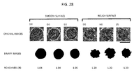
- a specifically quantified index for purifying a cardiac muscle cell by image recognition is unclear from the viewpoint of making the process automatic.
- Narrowing an aqueous solution of sample by use of side sheath liquids may undesirably dilute the aqueous solution of sample.
- Japanese Laid-Open Patent Publication No. 2011-257241 discloses a technology for detecting the presence/absence of a cancer cell in the blood.
- a fluorescence dye is attached to an antibody selectively bonded to a molecule (cancer marker) present only on a surface of a cancer cell, and the resultant antibody is reacted with blood.
- a cancer cell if being present in the blood, emits fluorescence.
- This technology is realized by the following method and device structure.
- Blood flowing in a microchip while containing a cancer cell is irradiated with fluorescence excitation light, and then the fluorescence emitted from the cancer cell is caused to pass, a plurality of times, a mirror (dichroic mirror) that reflects light of a particular wavelength and transmits light of the other wavelengths.
- a mirror dichroic mirror
- fluorescence of a particular wavelength band is extracted.
- the amount of the fluorescence of each particular wavelength band is measured by a light detector.
- the amount of fluorescence from the cancer cell, which is to be detected when the light passes the dichroic mirror is attenuated in accordance with the number of times the light passes the dichroic mirror.
- the fluorescence intensity measured at each wavelength band involves an error caused by the passage through the dichroic mirror. Especially, it is difficult to detect weak fluorescence at a wavelength on later stages. For this reason, it is difficult to quantitatively detect the multiple-stained cancer marker molecule.
- a cancer cell may be irradiated with excitation light of a plurality of different wavelengths, so that the emitted fluorescence of a plurality of wavelengths can be detected at the same time.
- light needs to pass a plurality of dichroic mirrors having excitation wavelengths that overlap the fluorescence wavelengths, so that light is divided into components each having a different wavelength. This complicates the device structure and also requires each wavelength band to be narrowed. This further attenuates signal fluorescence.
- the present inventors provide a cell analysis device capable of identifying, at high speed, the type, state and number (concentration) of cancer cells flowing in the blood while having a metastatic ability.
- the present invention provides the following device, system, and method.
- the present invention also provides the following on-chip cell sorter system and a method and an optical module for identifying a cancer cell candidate in the blood from a cell sample solution derived from a test subject by use of the system.
- the present invention further provides the following on-chip cell sorter system.
- An on-chip cell sorter system comprising:
- a trace amount of target cells in the blood can be purified in units of one cell, and gene information and expression information of the target cells can be analyzed correctly.
- the target cells are clustered or not (whether the target cells are solitary cells or not).
- the present invention it can be determined whether the cells are in an apoptosis state or not.
- the present invention it is made possible to measure only the recovered cells regarding the inner state thereof at a one-cell level and to perform genome analysis/expression analysis on only the recovered cells at a one-cell level.
- cell information such as the difference in the cell size, the size ratio between the nucleus inside the cell and the cytoplasm, or the like can be acquired, and the cells can be distinguished and purified based on such information.
- a cell such as a spore of Bacillus anthracis or the like can be analyzed regarding the substance therein at high speed while contamination is minimized.
- cells in a division period in the blood are recovered, and thus cells having a cell division ability such as cancer cells in the blood or stem cells can be recovered.
- multinucleated cells and cell clusters which are candidates for a cancer cell circulating in the blood, can be effectively recovered.
- the present invention it is made possible to excite, at the same time, cells labeled with fluorescence antibodies of a plurality of wavelengths by excitation light of a plurality of wavelengths, and to detect the plurality of emitted fluorescence components at the same time.
- cells which may be targets can be effectively recovered.
- a cell analysis device generally includes:
- the above-described three modules (1) through (3) are combined and continuously operated in the above-described order. Since the cells are continuously transferred by the flow path, extinction of a part of a trace amount of cells due to contamination or operation can be minimized.
- the cell analysis device By use of the cell analysis device according to the present invention, it is detected and checked whether cells are fluorescence-labeled or not on a one-cell level. It is confirmed that the fluorescence-labeled cells are solitary cells that are not clustered. It can also be determined whether the cells are in an apoptotic state or not. Therefore, the cell analysis device according to the present invention can separate and purify cells based on indices, which are not usable for identification by the conventional scattered light-detecting cell sorter technology.
- stained cells can be selected and recovered correctly in units of one cell.
- the state of each of the cells to be recovered for example, whether the cell is in an apoptotic state or not, can be checked.
- Gene information/expression information of each cell can be analyzed together with the fluorescence information and the cell state information.
- the cell enrichment/staining/decoloration section in (1) above is operated as follows. Cells in a trace amount contained in a reaction solution that is transferred from the module on the immediately previous stage by a non-contact force are continuously caught and enriched. When a certain number of cells are caught, a cell-labeling staining liquid is introduced to stain the cells. After the cells are stained, the reagent that is not bonded to the cells is removed by washing. Then, the cells are transmitted to the next module at a certain concentration.
- the cell enrichment/staining/decoloration section uses, for example, a cell catching/enrichment technology that utilizes a feature of cells that cells are gathered by a "dielectric electrophoretic force", which is a non-contact force generated by an AC electric field applied by a metal electrode formed in a microscopic flow path.
- a dielectric electrophoretic force which is a non-contact force generated by an AC electric field applied by a metal electrode formed in a microscopic flow path.
- the means in (2) that performs cell separation/purification in units of one cell based on the image detection results is operated as follows. Detailed information on the cells such as the difference in the cell size, the size ratio between the nucleus inside the cell and the cytoplasm, or the like is acquired as image information, and the cells are purified based on such information.
- image information such as the difference in the cell size, the size ratio between the nucleus inside the cell and the cytoplasm, or the like is acquired as image information, and the cells are purified based on such information.
- a high-speed camera is used for acquiring an image. Light emission from a light source is adjusted so as to be suitable to the shutter cycle of the high-speed camera, so that light is emitted from the light source only for a certain time duration among the time period, in which the shutter is clicked.
- a target cell is irradiated with light from a light source that is capable of controlling high-speed light emission, such as an LED light source, a pulsed laser light source or the like, for only 1/10 of the shutter speed.
- a light source that is capable of controlling high-speed light emission, such as an LED light source, a pulsed laser light source or the like, for only 1/10 of the shutter speed.
- a conventional cell sorter structured as the above-described separation/purification means on a chip has the following problem.
- a cell to be introduced into the cell sorter is separately enriched by an enrichment step by use of a centrifuge or the like. Therefore, the cell may be contaminated during the step.
- the steps are performed on a chip in a closed state except for the steps performed by an optical system. Namely, cell enrichment is performed directly on a chip, and a liquid transfer section and a culture tank for separated cells are also formed on a chip. Owing to this structure, contamination or loss of cells does not occur, and also the procedure is simplified and the process time is shortened. Thus, the device is made easier to use.
- the steps are performed in a closed state, it is made unnecessary to be concerned with contamination also in another case where it is indispensable to prevent contamination of cells derived from a test subject tissue, for example, in separation of stem cells, clinical examinations or the like.
- main parts of the cell sorter are put into a chip, and thus complete prevention of cross-contamination of devices or the like is realized.
- the present invention provides a cross-contamination-free cell separation system, which is indispensable in the medical field, especially in the field of degenerative medicine.
- the cells assumed in the present invention range from small cells such as bacteria to large animal cells (e.g., cancer cells) or the like.
- the cell size is typically in the range of about 0.5 ⁇ m to 30 ⁇ m.
- a first issue to consider is the flow path width (cross-sectional shape).
- the flow path is formed in one surface of a substrate to have a thickness of, typically, about 10 to 100 ⁇ m substantially two-dimensionally. An appropriate thickness is about 5 to about 10 ⁇ m for bacteria and is about 10 to about 50 ⁇ m for animal cells.
- a cell analysis device typically includes, in one chip, a cell enrichment section having a function of enriching cells, a cell arraying section and a cell separation/purification section having a function of separating and purifying cells after the cell enrichment, and an optical analysis section that identifies and distinguishes cells to be separated and purified.
- a sample solution which has not been enriched is introduced into the cell enrichment section from one entrance thereof, and is discharged from a discharge section located in a downstream part of the cell enrichment section.
- the device may include means that apply an external force to the cells so as to enrich the cells and direct the cells toward an enriched cell recovery opening located in a side wall of the enrichment section.
- the external force may be an ultrasonic radiation pressure, a gravitational force, an electrostatic force or a dielectric electrophoretic force, but is not limited to these.
- the means that apply an external force are located at a position, at which an external force can be applied in a direction that is perpendicular to the flow of the sample solution in the enrichment section and toward the enriched cell recovery opening.
- the cells flowing in the flow path are supplied with an external force so as to be arrayed at a center of the flow path, so that all the cells can be transferred downstream to one of the two branched flow paths.
- the arrayed cells only the cells to be recovered are further supplied with an external force to change the position of the cells. In this manner, only the cells provided with the further external force are introduced into one of the two branched flow paths.
- a specific external force may be applied by cell arraying means that arrays the cells to nodes of a stationary wave by an ultrasonic radiation pressure.
- an array of wedge-like electrodes may be combined, so that the cells can be arrayed at the positions of the apexes of the wedges.
- the cell detection function of the cell analysis device is provided by the image-detecting one-cell separation/purification section in (2).
- a CCD camera for observation is set upstream of the flow path branch point, and a cell separation area is provided downstream with respect thereto when necessary.
- the fluorescence can be detected by a light detector.
- the flow path branch point which is the cell separation area, is set downstream of the detection section.
- an external force is applied to the cells in the cell sorting section for example as follows.
- a dielectric electrophoretic force is used, a pair of comb-like electrodes are provided to form a flow path where the cell can be separated and discharged.
- an electrostatic force is used, a voltage is applied to the electrodes to change the position of the cells in the flow path. At this point, the cells are generally charged negative and therefore are moved toward a positive electrode.
- the pressure, by which a sample solution is introduced into the chip is a driving force for transferring the solution. Therefore, it is desirable that a waste liquid exit (outlet 213) of a cell enrichment section 215, a purified cell exit (cell recovery section 224) of a cell sorting section 217, and a waste liquid exit (waste liquid recovery section 223) of the cell sorting section are structured to have substantially the same pressure (see FIG. 4B ).
- a flow path resistance adjustment section for pressure adjustment is provided immediately before an exit of each of thin flow paths and S-shaped long flow paths.
- An algorithm of cell recognition and separation has the following features.
- the cells When cells are to be recognized from an image and evaluated, a part of the flow path that is downstream of the joining point of flow paths is observed by a CCD camera, and measurement is performed on a planar range. Thus, the cells are identified by image recognition and traced. In this manner, the cells can be separated with certainty. What is important in this case is the image capturing rate. With a common camera having a video rate of 30 frame/sec., a part of the cells is not recognized in the image. With a capturing rate of at least 200 frames/sec., cells flowing at a relatively high speed in the flow path can be recognized.
- the state of cell recognition varies in accordance with the transfer rate or the type of the cells as described above. In some cases, some cells run past the other cells. Therefore, when each cell first appears in the image frame, the cell is numbered. The cell is managed by the same number until disappearing from the image frame. Namely, the cell images transferring through a plurality of continuous frames are managed by numbers. The cells are linked in different frames under the conditions that in each frame, the cells are transferred from an upstream area to a downstream area and that the transfer rate of a specifically numbered cell that is recognized in the image is within a certain range, the starting point being the cell's first appearance in a frame. In this manner, even if some cells run past the other cells, each cell can be traced with certainty.
- the cell can be recognized as described above.
- the cells are each numbered as follows. First, the cell image is binarized, and the center of gravity thereof is found. The luminance centroid, the surface area, the perimeter length, the longer diameter and the shorter diameter of the binarized cell image are found, and the cell is numbered by use of these parameters. Each cell image is automatically stored as an image at this point, which is useful for the user.
- An index for separation may be the information such as the luminance centroid, the surface area, the perimeter length, the longer diameter, the shorter diameter or the like as described above.
- fluorescence detection may be performed in addition to the above-described process on the image, and information obtained by use of the fluorescence may be used as an index for separation.
- the cells obtained by the detection section are separated in accordance with the numbers thereof. Specifically, based on the image captured at a predetermined time duration, the transfer rates (V) of the numbered cells are calculated.
- the voltage application timing is set to (L/V) to (L/V+T). In this manner, when cells of target numbers are between the electrodes, the cells are electrically sorted in accordance with the voltage application time (T) and thus separated.
- the high-speed one-cell genome analysis/expression analysis means in (3) used in the present invention has the following structure for achieving the above-described object.
- the reaction control device to be used includes means that use, as mediums of heat exchange, liquids that have a large heat capacity and are respectively kept at the plurality of temperatures, to which the temperature of the sample liquid is to be changed.
- the means change the liquids having a large heat capacity and a plurality of different temperatures at high speed.
- the reaction control device also includes a microscopic reaction tank, in which the heat exchange between the liquids having a large heat capacity and the sample liquid is rapidly performed.
- a reaction control device used in the present invention includes a microscopic reaction tank formed of a structure and a material suitable to heat exchange, a reaction tank heat exchange tank that allows a liquid of a suitable temperature to each reaction to be circulated outside the microscopic reaction tank, a plurality of liquid reservoir tanks containing a heat source that maintains the temperature of a liquid with high precision, a switching valve system that guides a liquid from any liquid reservoir tank to the outside of the reaction tank in order to change the temperature in the microscopic reaction tank rapidly, and a mixture preventing mechanism that prevents mixture of liquids of different temperatures at the time of switching performed by the valve system.
- Controlling the temperature of the reaction tank by use of circulating liquids has the following advantages.
- the temperature of a liquid kept circulating is constant. Therefore, the temperature of the surface of the reaction tank and the temperature of the liquid are equilibrated instantaneously.
- the heat capacities of the reaction tank and the sample are negligibly small as compared with that of the refluxing liquid. Therefore, even if a liquid is deprived of heat locally, a heat gradient does not basically occur because the liquid is kept flowing. Needless to say, the temperature of the reaction tank never exceeds the temperature of the liquid.
- a temperature change of 30 degrees or greater can be caused within 0.5 sec.
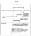
- FIG. 1 shows an example of procedure, performed by use of a cell analysis device according to the present invention, from sampling of a blood sample to analysis.
- a blood sample sampled from a patient is introduced into a cell enrichment/staining section. Only a cell component is extracted from the blood.
- a fluorescent labeling agent such as a fluorescent cancer marker or the like is added to be reacted with the sample cell. Then, an excessive portion of the fluorescent labeling agent that was not reacted is removed by washing, so that the reaction product is adjusted to be a solution having a cell concentration optimal for an image-detecting one-cell separation/purification section on the next subsequent stage. Then, the solution is introduced into the image-detecting one-cell separation/purification section.
- the image-detecting one-cell separation/purification section it is checked, as primary detection, whether there is fluorescence emission or not, based on fluorescent labeling at a one-cell level. In this manner, it can be checked whether the cells can be target cells or not by use of a conventional labeling technology. Then, cells that emit fluorescence and thus can be target cells are imaged by a high-speed camera. The resultant image is analyzed in real time to determine (1) whether the cells emitting fluorescence are each a solitary cell or in a cell mass together with other cells, or (2) whether the cells emitting fluorescence are in a normal state or in, for example, an apoptosis state, in which the nucleus of the cell and the shape of the cell are deformed.
- the normal cells or the cells in an apoptosis state can be recovered and introduced into a gene analysis/expression analysis section on the next stage that is capable of performing analysis on even a trace amount of sample at high speed. Then, each form of cells can be subjected to gene analysis and expression analysis separately. In the case where the cells are in a cell mass, the cell mass is not recovered even when containing cells emitting fluorescence because cells other than the target cells are also contained.
- the cells identified and purified at this stage can be re-cultured in a contamination-free state in units of a purified cell, instead of being introduced into the gene analysis/expression analysis section.
- the gene analysis/expression analysis section performs gene identification or expression identification on the introduced cells in units of a small number of cells, namely, in units of one cell or in units of a group of the same cells, in which the cells are determined to be the same cells based on information obtained from the image-detecting one-cell separation/purification section.
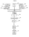
- FIG. 2 shows an example of overall structure of a cell analysis device system 1 that realizes the procedure shown in FIG. 1 .
- the device system 1 includes an enrichment/staining/decoloration module 10 that performs a pre-process on cells in a blood sample introduced thereto, an image-detecting one-cell separation/purification module 20 that identifies and purifies each of the cells, a one-cell genome analysis/expression analysis module 30 that performs gene analysis or expression analysis on the purified cells, a liquid transfer module 40 that transfers the sample between the modules, and a control/analysis module (computer) 50 that analyses the analysis results.
- an enrichment/staining/decoloration module 10 that performs a pre-process on cells in a blood sample introduced thereto
- an image-detecting one-cell separation/purification module 20 that identifies and purifies each of the cells
- a one-cell genome analysis/expression analysis module 30 that performs gene analysis or expression analysis on the purified cells
- a liquid transfer module 40 that transfers the sample between the modules
- FIG. 3 through FIG. 6 each show an example of structure of each of the modules shown in the example in FIG. 2 .
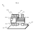
- FIG. 3 shows an example of structure of the cell enrichment/staining/decoloration module 10 that performs a pre-process on cells in a blood sample derived from a subject (e.g., cancer patient) introduced thereto.
- the cell enrichment/staining/decoloration module 10 is located on a chassis 114 integrally therewith.
- the module includes vessels or reservoirs (101, 102, 103) that respectively hold solutions of sample cell sample, staining agent, and washing detergent.
- the solutions can be each introduced via a separation head 104 attached to a rotatable arm 115 into a chamber 107 (a plurality of chambers 107 are referred to collectively as a enrichment chamber 108).
- the chambers 107 are located on a turn table 105 and have a enrichment/decoloration filter 106 attached to a bottom surface thereof.
- a sample cell sample such as blood or the like is introduced into the enrichment chamber 108.
- a liquid component thereof is discharged via the filter to a waste liquid recovery tube 110 by a pressure pump 109.
- a staining liquid is introduced by the use of the separation head 104. After a reaction is continued for a certain time duration, the staining liquid is also discharged by the pressure pump 109.
- a decoloration agent is introduced into the enrichment chamber 108, and thus an excessive portion of the staining agent is washed and discharged.
- a diluent generally also acting as a washing detergent is introduced to dilute the cells so that the cell solution has a desired concentration, and the cell solution is introduced into a recovery tube 112 via a recovery head 111 having a recovery chip 113 at a tip thereof.
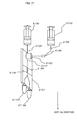
- FIG. 4 shows an example of structure of the image-detecting one-cell separation/purification module 20 that identifies and purifies each cell.
- the image-detecting one-cell separation/purification module 20 includes an optical system including a light source 201, a mirror 202, a light collection lens 203, a dichroic mirror 204, a filter 205, a light detection element 206 for detecting fluorescence, a high-speed camera 207 and a photodiode 208 for detecting scattered light; and also includes a cell sorter chip 209, into which a cell sample is introduced.
- a plurality of pieces of information can be detected at the same time on the cells passing the cell sorter chip 209 by use of the light source 201 such as a pulse laser, a high-luminance LED light source or the like, the light detection element 208 such as a photodiode or the like that detects passage of the cells based on scattered light, the high-sensitivity light detection element 206 such as a photomultiplier or the light that detects fluorescence, the high-speed camera 207 and the like.
- the light source may generate light continuously. However, in order to produce an image having a higher spatial resolution with no blur, the light source can generate pulsed light in synchronization with the shutter cycle of the high-speed camera 207. In this manner, an image having a higher temporal resolution can be obtained with a shorter time of light radiation.
- a process using an image and a process using fluorescence or scattered light may be combined, needless to say.
- Image data obtained by the high-speed camera 207 can be displayed on a monitor of the computer 50 so that a user can view the image.
- a plurality of assemblies each including a part of the optical system from the dichroic mirror 204 via the filter 205 to the fluorescence detector 206 may be combined. The number of the assemblies are set in accordance with the number of types of fluorescence to be observed.
- the filter 205 is appropriately adjusted so that a plurality of types of excitation light is transmitted through the filter 205, and the cells are irradiated with light of a wavelength that is different from the wavelength of the fluorescence to be detected on a later stage.
- fluorescence observation results on a cell image can be used as data.
- An algorithm of cell recognition and separation has the following features.
- the state of cell recognition varies in accordance with the transfer rate or the type of the cells as described above. In some cases, some cells run past the other cells. Therefore, when each cell first appears in the image frame, the cell is numbered. The cell is managed by the same number until disappearing from the image frame. Namely, the cell images transferring through a plurality of continuous frames are managed by numbers. The cells are linked in different frames under conditions that in each frame, the cells are transferred from an upstream area to a downstream area and that the transfer rate of a specifically numbered cell that is recognized in the image is within a certain range the starting point being the cell's first appearance in a frame. In this manner, even if some cells run past the other cells, each cell can be traced with certainty.
- the cell can be recognized as described above.
- the cells are each numbered as follows. First, the cell image is binarized, and the center of gravity thereof is found. The luminance centroid, the surface area, the perimeter length, the longer diameter and the shorter diameter of the binarized cell image are found, and the cell is numbered by use of these parameters. Each cell image is automatically stored as an image at this point, which is useful for the user.
- An index for separation may be the information such as the luminance centroid, the surface area, the perimeter length, the longer diameter, the shorter diameter or the like as described above.
- fluorescence detection may be performed in addition to the above-described process on the image, and information obtained by use of the fluorescence may be used as an index for separation.
- the cells obtained by the detection section are separated in accordance with the numbers thereof. Specifically, based on the image extracted at a predetermined time duration, the transfer rates (V) of the numbered cells are calculated.
- the voltage application timing is set to (L/V) to (L/V+T). In this manner, when cells of target numbers are between the electrodes, the cells are electrically sorted in accordance with the voltage application time (T) and thus separated.
- the structure includes a series of precision-processed flow paths, located two-dimensionally on a planar chip, in which the cells in the sample solution are enriched, arrayed and purified, and also includes means that causes a force to act on the cells incorporated into the chip.
- FIG. 4B schematically shows an example of the cell sorter chip 209 provided on the chip.
- a micro-flow path 211 is provided in the chip substrate 210, and an opening communicating to the flow path is provided in a top surface thereof.
- the opening acts as a supply opening for samples or necessary buffer solutions (mediums).
- the flow path may be formed by so-called injection molding of injecting a plastic material such as PMMA or the like into a die or by bonding a plurality of glass substrates.
- the size of the chip is, for example, 50 x 70 x 1 mm (t), but is not limited to this.
- a PMMA plastic material for example, a 0.1 mm-thick laminate film is thermally pressure-contacted.
- 0.1 mm-thick glass plates are optically adhered together. Owing to this, cells flowing in grooves or through-holes formed in an inner surface of the chip, or in the flow paths or wells, can be observed by an optical microscope of a high magnification. For example, the cells flowing in the flow paths can be observed by use of an objective lens having a numerical aperture of 1.4 and a magnification of 100 through a 0.1 mm-thick laminate film. In the case where a highly light-transmissive plastic material is used, the cells can be observed even from above the chip substrate 210.
- the cells assumed in the present invention range from small cells such as bacteria to large animal cells such as cancer cells or the like.
- the cell size is typically in the range of about 0.5 ⁇ m to 30 ⁇ m, but is not strictly limited to this range. Any size of cells are usable as long as the present invention is effectively usable.
- a first issue to consider is the flow path width (cross-sectional shape).
- the flow path 211 is formed in one surface of the substrate to have a thickness of, typically, about 10 to 100 ⁇ m substantially two-dimensionally. An appropriate thickness is 5 to 10 ⁇ m for bacteria and is 10 to 50 ⁇ m for animal cells.
- the sample solution is first introduced from an inlet 212 into the micro-flow path 211 by a syringe pump or cell introduction means that does not generate a pulsating flow such as air pressure or the like.
- the cell-containing sample solution introduced into the micro-flow path 211 flows along a flow line 218 of pre-voltage application particles toward an outlet 213 on the downstream side, and is discharged.
- the external force the cells are enriched while advancing along a flow 219 of the post-voltage application cells.
- a cell-enriched solution having a high concentration that is at least 100 times the concentration of the sample solution at the inlet 212, is introduced into the cell-enriched solution inlet 214.
- the external force to be applied to the cells may be an ultrasonic radiation pressure, a gravitational force, an electrostatic force or a dielectric electrophoretic force.
- an ultrasonic radiation pressure is used
- an ultrasonic wave is generated so as to advance toward the cell-enriched solution inlet 214 in a direction perpendicular to the flow of the sample solution.
- the flow 219 of the post-voltage application cells can be formed by the radiation pressure of the ultrasonic wave.
- the ultrasonic wave may be introduced by bonding a PZT-type piezoelectric element to the surface of the chip 209.
- an array of comb-like electrodes is located on a surface of a piezoelectric element and is bonded to a surface of a cell enrichment section 215, so that a surface acoustic wave is generated in the cell enrichment section 215.
- the ultrasonic wave effusing therefrom is introduced into the cell enrichment section 215.
- the spatial location of the chip 209 may be adjusted such that the direction of the gravitational force is perpendicular to the flow of the sample solution and is toward the cell-enriched solution inlet 214.
- the chip 209 may be located on a rotatable discus such that the direction of the gravitational force is perpendicular to the flow of the sample solution and such that the direction toward the cell-enriched solution inlet is the same as the radial direction of the discus.
- electrodes are located on the side wall of the micro-flow path 211 so that the cells are supplied with the external force directed toward the side wall. In this case, which charge is to be applied may be determined based on whether the potential of the surface of each target cell is positive or negative.
- the flow path distance of the micro-flow path 211 needs to be flexibly adjusted in accordance with the type and strength of the external force to be applied to the cells.
- the micro-flow path 211 needs to be sufficiently long.
- electrodes may be located in the cell enrichment section 215 such that the direction of the dielectric electrophoretic force is perpendicular to the flow of the sample solution and is toward the cell-enriched solution inlet 214.
- cells in the cell-enriched solution introduced from the cell-enriched solution inlet 214 are arrayed in a line along the flow in a convergence section 216.
- the cells arrayed in a line in this manner are measured in a cell detection area 218 that is on a stage before a cell sorting section 217, so that the type of each cell is determined.
- each cell is guided to a first outlet 221 or a second outlet 222, which are in two branched downstream areas in a cell sorting/branching section 220. Whether the cell is supplied with an external force in a direction perpendicular to an upstream-to-downstream flow or not controls whether the cell is guided to the first outlet 221 or the second outlet 222.
- an example of an electrode arrangement is as follows.
- a pair of electrodes 225 having wedges (V-shaped comb-like electrodes for convergence) are located alternately, and an AC voltage is applied to electrode contacts of the V-shaped comb-like electrodes for convergence.
- an external force can be applied to the cells so that the cells are transferred toward apexes of the wedges.
- the cells can be continuously enriched at the positions of the apexes of the wedges. What is important for the electrodes in this example is the shape of the electrodes located in the flow path.
- the electrodes have a protrusion in a downstream direction and form an array of comb-like electrodes that are not straight but have acute tips and are axially symmetrical. Owing to such a shape of the electrodes, the cells supplied with the dielectric electrophoretic force are guided and arrayed by the tips of the electrodes by a resultant force of a force of pushing the cells downstream along the flow and a force applied to the cells in a direction toward the acute tips. This occurs regardless of whether the dielectric electrophoretic force acts on the cells as a repulsive force or an attractive force.
- the acute tips of the electrode array are located at a position where the cells in the flow path are to be enriched, and thus the cells are gathered at the acute tips by a resultant force of a force of pushing the cells downstream along the flow and the dielectric electrophoretic force toward the acute tips.
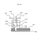
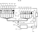
- FIG. 5 shows an example of structure of the one-cell genome analysis/expression analysis module 30 that performs gene analysis or expression analysis on purified cells.
- a reaction tank 301 is formed of an aluminum, nickel or gold thin plate having a plurality of depressions. The plate has a thickness of about 10 to 30 micrometers in the depressions areas. An area between adjacent depressions has a thickness of 100 to 500 micrometers so as to be entirely strong with certainty.
- the reaction tank 301 is secured to a bottom surface of a quadrangular or circular reaction tank frame, so as to be easily detached from a reaction tank heat exchange tank 302. A liquid to be introduced into the reaction tank heat exchange tank 302 is excessively heated by a heat source located in each of liquid reservoir tanks 303.
- a stirring mechanism is prepared in order to remove heat rapidly from a surface of the heat source and thus to uniformize the temperature in the liquid reservoir tank 303.
- a liquid in the liquid reservoir tank 303 is guided through the flow path by a pump 304.
- the liquid is guided to the reaction tank heat exchange tank 302, or is guided to a bypass flow path and directly returns to the liquid reservoir tank 303, by a switching valve 305.
- the temperature of the liquid is slightly controlled by an assisting temperature control mechanism 306, so that the temperature change in the liquid reservoir tank 303 is suppressed.
- the reaction tank heat exchange tank 302 basically includes an inlet A (307) and an inlet B (308) through which liquids of different temperatures are introduced.
- the number of the plurality of inlets matches the number of temperatures to which the temperature of a sample liquid is to be changed.
- three inlets are prepared.
- the number of the inlets is not limited to two as in this example.
- a plurality of outlets namely, an outlet A (309) and an outlet B (310) are prepared.
- the number of the outlets is not limited to two.
- the reaction tank may have any of various shapes. For example, there may be a reaction tank A, a reaction tank B, a reaction tank C and a reaction tank D.
- the liquid in the reaction tank heat exchange tank 302 may be water, or alternatively may be a liquid having a large heat capacity and a low viscosity.
- liquid ammonia or the like may be used.
- the sample liquid can have a temperature of 100°C with certainty.
- the liquid in the reaction tank heat exchange tank 302 has a freezing point lower than that of water, the liquid circulating in the device can be prevented from freezing while the temperature thereof is changed down to the freezing point of water with certainty.
- the reaction tank frame has an optical window through which excitation light having a fluorescent dye and fluorescence are transmitted, so that the fluorescence intensity of the fluorescent dye in the sample liquid, which is changed by a reaction of a sample liquid 311 in the reaction tank 301, can be measured. Such measurement can be performed for one or each of the plurality of reaction tanks 301.
- a fluorescence detector 312 is also provided, so that the time-wise change in the measured fluorescence intensity of each reaction tank 301 can be measured. In the example in FIG.
- a plurality of fluorescence detectors 312 each include an excitation light radiation mechanism and a fluorescence detection mechanism, so that different pieces of PCR amplification information on the plurality of reaction tanks 301 to which different primers or different sample liquids are dripped can be each measured independently.
- Fluorescence intensity data obtained by each fluorescence detector 312 is recorded by a control analysis section 313.
- the control analysis section 313 has a function of estimating the DNA amount or the mRMA amount in the sample liquid obtained by the PCR.
- the control analysis section 313 also has a function of acquiring switching information on the switching valve 305 and estimating, based on the time-wise change in the fluorescence intensity, whether or not the temperature of the post-valve switching sample liquid 311 has reached a target temperature, and also a mechanism of controlling the valve switching based on the estimation results.
- the estimation is performed based on the change of the amount of fluorescence intensity per unit time being decreased or nulled by utilization of that fluorescence extinction based on the motion of water molecules universally possessed by a fluorescent dye depends on the liquid temperature. This estimation is especially useful to check whether or not a high temperature state that denatures the DNA has been achieved.
- one detector is located for each reaction tank 301.
- a fluorescence excitation light source may be combined with a camera such as a cooled CCD camera that can perform quantitative detection of fluorescence, so that the change in the fluorescence intensity of a plurality of reaction tanks can be measured.
- a mechanical driving mechanism that is movable at high speed on an X-Y plane may be combined with the detectors, so that the fluorescence intensity of all the reaction tanks can be measured.
- a lyophilized reagent can be prepared in a bottom part of the reaction tank.
- a plug-like lyophilized reagent may be formed in a separation chip that is used to separate the sample, so that the reagent can be dissolved in the sample by moving the sample up and down.
- a lyophilized reagent is formed on a surface of a fiber ball formed of nylon fiber or the like, the fiber ball is inserted into the sample in the reaction tank, and the sample is stirred. In this manner, the lyophilized reagent can be dissolved.
- the reaction tank frame is formed of polystyrene, polycarbonate, PEEK, acrylic resin or the like, which is heat-insulating. It is also desirable that the surface area of the reaction tank frame which is bonded with the reaction tank 301 is suppressed low in order to raise or lower the temperature of the reaction tank 301 rapidly and highly precisely.
- a method for attaching the reaction tank 301 to the reaction tank heat exchange tank 302 a surface of the reaction tank frame is threaded and the reaction tube frame is screwed into the reaction tank heat exchange tank 302. It is desirable to attach a seal to the opening in order to keep the water tightness.
- a tapered reaction tank frame may be used so that the reaction tank 301 can be attached by use of only a pressure.
- valve switching mechanism There are opened at the same time for merely a moment. Owing to this, liquids of different temperatures can be suppressed from being mixed together, and the temperature control on the liquid reservoir tanks of the respective systems is made easier.
- the PCR may be first performed at 90°C for 10 seconds, and then the cycle of performing the PCR at 90°C for 1 second and then 60°C for 3 seconds may be repeated 40 times.
- FIG. 6 shows an example of the structure of the liquid transfer module 40 that transfers a sample between the modules.
- the liquid transfer module 40 includes a separation head 401 and a separation chip 402 through which a liquid is transferred between the modules located on a chassis 406.
- the liquid transfer module 40 also includes a Z-axis transfer guide 403 and a Z-axis transfer motor 404 that control the separation head in a height direction along a Z axis, and an arm rotation motor 405 as an arm rotation mechanism.
- the liquid transfer module 40 has the function of controlling the position of the separation head 401 on an X-Y plane by the Z-axis transfer guide 403, the Z-axis transfer motor 404 and the arm rotation motor 405.
- FIG. 7 shows an example of procedure from sampling to analysis of a sample as performed by use of a cell analysis device according to the present invention.
- the procedure is performed on a sample solution in which a nucleus component in a cell such as spore of Bacillus anthracis or the like is not easily eluted owing to a shell covering the cell.
- the procedure includes a step of fracturing the shell covering the cell before a step of performing expression analysis on the cell. Owing to the step of fracturing the shell covering the cell, the cell analysis device according to the present invention can analyze a cell such as a spore of Bacillus anthracis or the like with exactly the same means as the blood cell analysis means described above.
- FIG. 8 schematically shows an example of the basic structure provided for analyzing information on a cell such as a spore of Bacillus anthracis or the like; more specifically, information on the gene in the cell and expression thereof.
- the structure automatically fractures a shell of the spore or the like that covers the cell in a trace amount of sample.
- a trace amount of sample 802 is put into a vessel 801, and a rotator for fracturing is located in the vessel 801.
- the rotator 803 is pressed to the vessel 801 by a rotation shaft 804.
- the rotator 803 is rotated and revolved in the vessel, and thus a sample 805 in the trace amount of sample is ground by a grinding agent 806.
- the rotator 803 is removed, and thus the post-process sample 805 can be easily recovered.
- the rotator 803 and the vessel 801 have a simple structure, and therefore may be handled as expendables with no problem.
- FIG. 9 schematically shows variations of the basic cell fracture mechanism shown in FIG. 8 .
- the rotator In order to fracture the sample at a high efficiency, the rotator needs to be in close contact with the vessel.
- a vessel 811 accommodating a rotator 810 is held by a flexible body 812 formed of rubber or the like.
- a tip 814 of a shaft 813 is cut to be oblique. Therefore, when the shaft 813 is pressed to the rotator 810, the rotator 810 presses the vessel 811 downward and laterally. This deforms the flexible structure 812 and thus absorbs the pressure.
- a spring mechanism 815 which is deformable vertically and laterally may be incorporated into the rotation shaft as an element that releases the stress.
- FIG. 10 shows variations of the rotator and the rotation shaft of the cell fracture mechanism usable in the present invention.
- the tip of the shaft may be cut to be oblique ( FIG. 10a ), may be recessed to have a mild curve ( FIG. 10b ), or may be mortar-like ( FIG. 10c ).
- the rotator does not need to be completely spherical and may have a shape loosely engageable with the shaft ( FIG. 10d ).
- a semicircular rotator may be rotated by a rotation shaft having a tip cut to be oblique ( FIG. 10e ).
- the rotator may be egg-shaped ( FIG. 10f ) or may have a protrusion engageable with the rotation shaft ( FIG. 10g ).
- a dish-like rotator may be rotated by the shaft ( FIG. 10h ).
- FIG. 11 shows an example of a cell fracture step according to the present invention.
- a rotator 831 and a grinding agent 832 are accommodated in an air-tight manner ( FIG. 11a ).
- a seal 833 is broken ( FIG. 11b ) and a sample 834 containing cells is put into the vessel 830 ( FIG. 11c ).
- the rotator 831 is rotated while being pressed by a rotation shaft 835 ( FIG. 11d ), and thus the cells in the sample are fractured by the grinding agent 832 and a component 836 is eluted ( FIG. 11e ).
- the rotator 831 is removed from the vessel 830.
- the rotator may be removed by use of a negative pressure, a magnetic force or an electrostatic force.
- a mechanism that removes the rotator may be incorporated into the rotation shaft. Needless to say, a dedicated mechanism may be separately prepared.
- FIG. 12 provides conceptual views of a mechanism that is usable in the case where the cell fracture step according to the present invention is automated.
- a plurality of vessels 840 are integrally formed, and a rotator is accommodated in each vessel in advance in an air-tight manner.
- the seal may be broken, for example, by directly pressing the rotation shaft ( FIG. 12A ), by use of an opening cutter 841 attached to the rotation shaft ( FIG. 12B ) or the like.
- the relative positions of the shaft and the vessel can be automatically changed, so that a plurality of samples can be fractured one after another.
- FIG. 13 shows an example of an on-chip cell sorter chip according to the present invention that is usable in the cell analysis device system according to the present invention.
- a cell sorter chip 1301 axially symmetrical three flow paths are located in an upstream part (1302, 1304, 1306) and axially symmetrical three flow paths are located in a downstream part (1303, 1305, 1307), on a chip substrate.
- the flow paths in the upstream part and the flow paths in the downstream part are symmetrical to each other.
- the three flow paths join together while keeping a laminar flow and branch into the three flow paths on the downstream side while keeping this state. Therefore, the upstream central flow path 1302 in which a sample flows is guided toward the downstream central flow path 1303.
- the upstream side flow path 1304 is guided toward the downstream side flow path 1305, and the upstream side flow path 1306 is guided toward the downstream side flow path 1307. Entrances of the three upstream flow paths are respectively linked to entrance openings 1308, 1309 and 1310.
- the entrance opening 1308 for the upstream central flow path in which the sample flows is linked to a sample solution reservoir 1322.
- the entrance opening 1308 is typically (but not limited to being) provided with a small annular cap (or plug) so as to be isolated from the entrance openings 1309 and 1310 for the flow paths in which a sheath liquid accumulated in a sheath liquid reservoir 1311 flows. Thus, the sample solution is not spread around.
- a waste liquid reservoir 1312 is linked to exit openings 1313 and 1314 for the flow paths in which two side sheath liquids flow.
- a purified sample recovering reservoir 1323 is linked to an exit opening 1315 for the recovered purified sample.
- the exit opening 1315 is typically (but not limited to being) provided with a small annular cap so that the recovered purified sample is not spread to the waste liquid reservoir.
- the flow rate may be generated by a gravitational system by use of the difference between the liquid surface level of the sample reservoir and the sheath liquid reservoir and the liquid surface level of the waste liquid/recovered liquid reservoir, or by providing a top surface of each reservoir with a cap and thus using the pressurized air to apply a pressure to the liquid surface.
- a gravitational system by use of the difference between the liquid surface level of the sample reservoir and the sheath liquid reservoir and the liquid surface level of the waste liquid/recovered liquid reservoir, or by providing a top surface of each reservoir with a cap and thus using the pressurized air to apply a pressure to the liquid surface.
- the three flow paths upstream of the joining point and the three flow paths downstream of the joining point respectively match one another in the cross-sectional shape and the length from the joining point to the solution opening.
- each reservoir for the side sheath flow (or for the waste liquid) and the cross-sectional surface area of the corresponding inner reservoir for the sample/recovered sample is 1 (sample/recovery reservoir) : 2 (side sheath liquid reservoir/waste liquid reservoir).
- the ratio between the cross-sectional surface areas of the two types of reservoirs is defined as 1:2 so that the reservoirs have the same liquid surface level.
- This can be generalized as follows: it is desirable that the ratio between the total cross-sectional surface areas of the flow paths linked to the two types of reservoirs matches the ratio between the cross-sectional areas of the two types of reservoirs.
- each of the electrodes is typically formed of a gel electrode.
- a gel electrode for example, agarose gel having Nail dissolved therein is used so that an electrolyte acts as a current carrier.
- agarose gel in a sol state is put into each of Y-shaped flow paths 1316 via a corresponding entrance 1317.
- the Y-shaped flow paths 1316 are provided to be filled with the gel.
- the gel is not allowed to enter the cell sorter flow path and is stopped at the border by surface tension.
- An advantage of using a gel electrode is as follows.
- a cable 1319 of platinum or the like that is connected to a power source 1310 in order to apply an electric field is inserted into the gel introduction point.
- a current can be applied with no bubble being generated even when the voltage is raised to a level at which bubbles are generated in the flow path with a usual metal electrode.
- the on/off state of the electric field application can be adjusted by use of, for example, a switch 1321.
- FIG. 14 schematically shows an example of cross-section of the upstream reservoirs taken along line A-A in FIG. 13 .
- a flow path 1409 is buried.
- a top surface of an outer sheath liquid reservoir 1403 is covered with a cap 1402, and thus an air pressure having an appropriate flow rate is supplied from a pressurized air introduction pipe 1405.
- the flow path 1409 in which a sample flows is linked to a sample reservoir 1404, so that the sample solution and the sheath liquid are not mixed together.
- the ratio between the number of the flow path for the sample reservoir and the number of the flow paths for the sheath liquid reservoir is 1:2
- the ratio between the cross-sectional surface area of the sample reservoir and the cross-sectional surface area of the sheath liquid reservoir is 1:2.
- a liquid supply mechanism may be additionally provided.
- Such a mechanism includes a sample solution introduction tube 1406 or a sheath liquid introduction tube 1407 and a water level measurement sensor 1408 incorporated into a wall surface of each reservoir.
- the water level measurement sensors 1408 perform conductivity measurement. Owing to this structure, when the water level is below a certain level, the sample solution can be supplied via the tube until the water level is returned to the certain level.
- the water level measurement sensors 1408 may be each formed of an electrode, an electrode pair or the like located at a lower limit and an upper limit of the water level to be set.
- FIG. 15 shows an example of another structure of a cell sorter according to the present invention for handling a larger amount of sample.
- a chip 1501 On a chip 1501, three large reservoirs 1502 are located in upstream parts of three flow paths respectively. A pressure from an air pressure application device 1503 can be distributed to these reservoirs flexibly via a pressure sensor 1504 by use of distribution valves 1505.
- the sorted (purified) sample and a waste liquid are respectively recovered by a sorted sample recovery reservoir 1506 and a waste liquid recovery reservoir 1507 which are located downstream of the chip.
- FIG. 16 schematically shows an actual procedure of recovering a sample in a chip.
- a sample solution flow 1601 flowing from an upstream position advances to a cell monitor area 1604 while being held between two side sheath solution flows 1602 and 1603.
- the shape of each cell is distinguished and it is checked whether fluorescence labeling is present or absent. Based on the results, the cells are separated at a downstream position.
- the cell monitor area 1604 the cell is allowed to flow downstream to a sorted sample recovery flow path 1606.
- a voltage is applied to two gel electrodes 1605 located to face each other, regardless of whether the charge of the cell or the particulate is positive or negative.
- the cell or the particulate is transferred to either one of the two side sheath flows 1607 and thus can be discharged.
- FIG. 17 provides schematic views illustrating one index for recovering a cell by an image-processing cell sorter.
- the cell is in the G0 period and contains a nucleus ( FIG. 17A(a) ).
- the nucleus is clearly recognized as a black sphere in the cell ( FIG. 17B(a) ).
- FIG. 17A(b) the nucleus has separated ( FIG. 17A(b) ). Therefore, the nucleus cannot be confirmed to be present even by image recognition of the cell ( FIG. 17B(b) ).
- the conventional labeling technology such as antibody labeling or the like, it is difficult to check the state of the cell.
- such image recognition can be performed to check the shape of the cell and also to recover the cell in the division period based on the presence/absence of the nucleus in the cell.
- most of the normal cells flowing in the blood have past the final differentiation stage.
- recovery of cells in the division period in the blood according to the present invention makes it possible to recover cells having a cell division capability such as cancer cells in the blood, stem cells or the like.
- FIG. 18 shows an example of a timing chart of an actual operation of an image-recognizing cell sorter according to the present invention by use of a flash light source.
- a flash light source In the case where a high-speed camera is used to observe cells transferring in a chip, blur can be prevented as follows. A spatial resolution for one pixel of the camera is found based on the magnification of the objective lens. In the case where the transfer rate of the sample flow has been determined, the transfer amount of one pixel at the determined flow rate is found. The flash light is turned on for the time duration required for the transfer. Namely, the flash is fired once during each shutter interval with the flash time being set as:
- the present invention also provides an on-chip cell sorter system. Illustrative embodiments thereof will be described hereinafter.
- control of each of the sections e.g., image acquisition and analysis by use of an optical system, application of an external force by an external force application device, etc.
- a control device including a personal computer or the like, like in the above-described embodiment.
- FIG. 19 schematically shows an example of a structure of an optical system that is included in an image-detecting one-cell separation/purification (cell sorter) module and prevents image blur.
- the magnification ratio of the target image is determined based only on the magnification of the objective lens.
- the focal depth and the depth of field of the optical system depend on the magnification and the numerical aperture of the objective lens. As the magnification of the objective lens is increased, the focal depth and the depth of field of the optical system are decreased.
- the flow path In the case where targets in a microscopic flow path are observed and the targets are cells, in order to allow various sizes of samples, including microscopic samples having a size of about several micrometers and clusters having several tens of micrometers, to flow, the flow path needs to have a sufficient width and a sufficient depth for the maximum size of sample to flow.
- the resolution of the image In order to distinguish the type of the sample by image recognition, it is more preferable that the resolution of the image is higher.
- an objective lens having a higher numerical aperture.
- the focal depth is decreased, which results in decrease in the depth of field in the flow path.
- the magnification ratio of the target sample is increased while the depth of field is made approximately equal to the surface level of the flow path.
- This can be realized by first selecting an objective lens having a numerical aperture with which the focal depth and the depth of field thereof are approximately equal to the surface level of the flow path, and then providing a zoom lens in a stage after the objective lens.
- an objective lens and a zoom lens may be combined and a magnified image thereof may be captured by an image capturing device such as a CCD camera or the like.
- the height that can be imaged when a 10x objective lens having a numerical aperture (NA) of 0.3 is used is measured.
- NA numerical aperture
- an image having a height of up to about 15 ⁇ m can be captured with no problem.
- the maximum height of the image that can be captured with no blur is merely about 5 ⁇ m.
- FIG. 19C shows the results of measurement with a zoom lens having a numerical aperture of 0.28 being provided in a stage after this objective lens.
- an image obtained by a combination of a 10x objective lens and a 1x zoom lens, an image obtained by a combination of a 10x objective lens and a 2x zoom lens, and an image obtained by a combination of a 10x objective lens and a 4x zoom lens can be observed sufficiently well with no blur regardless of the difference in the magnification of the zoom lens, as long as the focal depth and the depth of field are each 25 ⁇ m or less.
- FIG. 20 shows a structure for solving a problem of the conventional art.
- a cell sorter chip is located horizontally. Therefore, the sample is precipitated at the bottom of the horizontal flow path, and this causes clogging.
- the cell sorter chip is located vertically, so that the precipitation direction of the cells is the same as the direction of the flow.
- a cell sorter chip 2001 in the cell sorter system is located vertically as shown in FIG. 20 , and an upstream part of the flow is in a top part and a downstream part of the flow is in a bottom part.
- a sample solution and a buffer solution are provided from a sample solution introduction device 2006 and a buffer introduction device 2003 respectively with a pressure applied thereto being controlled by use of a pressure sensor 2004.
- the sample solution and the buffer solution are introduced into respective reservoirs 2002 connected to a top surface of the chip.
- the flow in each flow path can be fine-adjusted by fine-adjusting the open/close state of a corresponding distribution valve 2005 in accordance with the pressure or the state of each reservoir.
- the liquids introduced from the reservoirs are joined together via a sample solution flow path 2007 or buffer flow paths 2008.
- the cells are transferred vertically along the flow in the flow path by sorting external force application mechanisms 2009.
- Each cell is transferred as described above based on the type of the cell distinguished by image acquisition or the results of quantitative measurement of fluorescence or scattered light, for example, the results of labeling and measurement of fluorescence or the like.
- the cells can be recovered by a plurality of downstream reservoirs 20101, 20102 and 20103.
- FIG. 21 shows an example of another structure of the cell sorter shown in FIG. 20 in which the chip is located vertically.
- a cell sorter chip 2101 in the cell sorter system is located vertically.
- An upstream part of the flow is in a top part and a downstream part of the flow is in a bottom part.
- a sample solution and a buffer solution are provided from a sample solution introduction device 2106 and a buffer introduction device 2103 respectively with a pressure applied thereto being controlled by use of a pressure sensor 2104.
- the sample solution and the buffer solution are introduced into a reservoir 2102 connected to a top surface of the chip.
- the sample solution which is introduced into the reservoir 2102 after passing a sample solution introduction flow path 21061 formed of a capillary tube, is introduced into a flow path 2107 as being held between the buffer solutions.
- the cells flowing in the flow path 2107 are transferred vertically along the flow in the flow path by sorting external force application mechanisms 2109.
- Each cell is transferred as described above based on the type of the cell distinguished by image acquisition or the results of quantitative measurement of fluorescence or scattered light, for example, the results of labeling and measurement of fluorescence or the like.
- the cells can be recovered by a plurality of downstream reservoirs 21101 and 21102.
- FIG. 22 schematically shows an example of a structure of a part of the cell sorter chip shown in FIG. 21 , where a sample solution and a buffer solution are joined together.
- a sample solution is introduced into the flow path 2107 from the capillary tube 21061, and a buffer solution is introduced into the reservoir 2102 connected to the top surface of an end point of the flow path 2107.
- the reservoir 2102 is located so as to introduce the buffer solution into the flow path 2107.
- an exit of the capillary tube 21061 is located downstream of the reservoir section, so that the sample solution can be introduced into a desired position in the flow path of the buffer solution.
- the capillary tube 21061 is located closer to one lateral side of the flow path 2107.
- the capillary tube is used to introduce the sample solution into the flow path of the buffer solution.
- the capillary tube does not need to be used as long as the sample solution can be introduced into an area where a flow of the buffer solution is generated. Substantially the same effect is provided by a combination of precision-processed flow paths.
- FIG. 23 schematically shows an example of a structure of a chip that is in a cell sorter system and includes a mechanism that performs cell sorting.
- a sample introduction opening 23002 is located in an upstream part.
- a sample solution introduced into the sample introduction opening 23002 contains, in a mixed state, target particles 23003 to be recovered and unnecessary particles 23004 to be abolished.
- the sample solution flows in a micro-flow path 23005 and is first introduced into a particle arraying mechanism 23006.
- particle arraying external force inputs (electric force or sheath flow) 23007 are located.
- gel electrodes are located at both of two sides of the flow path 23005 to apply an electric field.
- a buffer solution is introduced.
- the type of each particle in the sample arrayed in a line is identified by a particle detection mechanism 23008, and in the next stage, the particles are separated by a particle purification mechanism 23009.
- particle purification external force inputs ((gel or metal) electrodes + electric force) 23010 are located.
- An electric force can be provided to the position of the particle purification mechanism 23009 by use of gel electrodes or metal electrodes.
- a target particle to be recovered reaches the particle purification mechanism 23009, the target particle is allowed to flow downstream with no application of an external force and is recovered at a recovery opening 23011.
- the particles are provided with an external force by the particle purification mechanism 23009 and thus can be guided to unnecessary particle reservoirs 23012 and 23013.
- FIG. 24 shows an example of electrode arrangement for providing an external force in a flow path of a cell sorter system.
- FIG. 24(a) is a schematic plan view
- FIG. 24(b) is a schematic cross-sectional view.
- two comb-like electrode parts namely, a metal thin film electrode first layer 24002 and a metal thin film electrode second layer 24003 overlap with each other while being shifted slightly.
- An insulating layer 24004 is provided between the layers 24002 and 24003.
- the second electrode 24003 is in direct contact with a sample flow path 24005.
- FIG. 24(c) shows a photograph of an example in which an array of comb-like electrodes is actually located on a bottom surface of the flow path with the above-described structure.
- FIG. 25 shows an example of electrode array arrangement for providing an external force in a flow path of a cell sorter system.
- FIG. 25(a) shows that sample particles 25004 introduced into a sample introduction opening 25001 flow in a micro-flow path 25002. It is now assumed that metal thin film-stacked parallel comb-like electrodes 25003 having the structure as shown in FIG. 24 are located in the flow path. When an AC electric field is generated in the metal thin film-stacked parallel comb-like electrodes 25003, the sample particles 25004 advance toward a top surface by a dielectric electrophoretic force. As shown in FIG. 25(d) , the flow path has a semicircular cross-section.
- the flow path has a semicircular cross-section.
- the flow path may have a triangular cross-section.
- metal thin film-stacked V-shaped comb-like electrodes 25005 are used.
- a repulsive force is generated from an electrode 25007 on the bottom surface of the flow path to guide the particles to the top wall, so that the particulates can be arrayed in a line at a center of the flow path owing to the shape of the top wall.
- sheath flow paths 25006 for a better solution are additionally provided on both of two sides of the flow path 25002, so that the particulates can be arrayed.
- FIG. 26 schematically shows an example of a process of cell purification performed in a flow path of a cell sorter system.
- a step of cell purification after the cell identification will be described.
- Target particles 26001, unnecessary particles (charged negative) 26002 and unnecessary particles (charged positive) 26003 flow in a micro-flow path 26004 in the state of being arrayed in a line.
- the target particle is guided to a flow 26006 directed toward a target particle recovery opening because the electrodes are in an off state.
- an unnecessary particle reaches the particle purification electrode 26005 area, an external electric field is turned on. Then, the unnecessary particle is attracted to a positive electrode or a negative electrode and thus is removed from the center of the flow path and guided to a flow 26007 or 26008 to an unnecessary particle reservoir.
- FIG. 27 provides schematic views showing an example of gel electrode arrangement for providing an external electric field in a flow path of a cell sorter system, and photographs showing an example of an actual chip.
- electrode gel liquid junction sections 27004 are provided adjacent to a micro-flow path 27001.
- the electrode gel liquid junction sections 27004 each act as a border that isolates the flow path 27001 from the gel.
- the electrode gel liquid junction sections 27004 prevent, by surface tension, the gel from leaking to the flow path 27001.
- side surfaces of the flow path 27001 are each formed of a line of a large number of columns instead of a wall, and the gel and the liquid flowing in the flow path contact each other via inter-column spaces.
- the width of each of the inter-column spaces is desirably 500 ⁇ m or less.
- End points of the gel filled with an electrolyte are each connected to a metal cable 27006.
- the electrodes are connected to a DC voltage source 27007, which performs ON/OFF control based on the observation results on the flowing particles by use of a voltage application switching mechanism 27008.
- a sample particle 27009 to be recovered reaches an area between the electrodes, an electric field is applied to the electrodes. As a result, the position of the particle in the flow path can be changed. In this manner, the particles can be purified.
- the gel electrodes are used.
- metal thin film electrodes 27010 may be used ( FIGs. 27(b) and (d) ).
- FIG. 28 is a schematic view showing an example of an identification process performed to separate cardiac muscle cells and fibroblasts from each other by use of an image in an image-recognizing cell sorter system.
- images in the top part of FIG. 28 that are captured by an image capturing mechanism of the cell sorter (top part: original images)
- a surface of the cardiac muscle cell is very smooth (smooth surface).
- a surface of the fibroblast is very rough (rough surface).
- These images are binarized into the images in the middle part of FIG. 28 (binary images) so that an image of a boundary surface of each type of cell is made clear.
- Length l of the perimeter of the boundary surface is measured based on the number of pixels in the boundary surface, and also the surface area S of the fully painted inner surface is calculated based on the number of the fully painted pixels.
- R l 4 ⁇ ⁇ ⁇ S
- FIG. 29 is a schematic view showing an example structure of a cell sorter system using a combination of water and oil.
- a sheath liquid reservoir 1311 is filled with oil such as silicone oil or the like having a specific gravity smaller than that of water.
- oil such as silicone oil or the like having a specific gravity smaller than that of water.
- FIG. 30 provides schematic views showing an example structure of an area where water and oil are joined together, in a cell sorter system using a combination of water and oil.
- an aqueous solution of sample is introduced into an aqueous sample solution introduction opening 3001 in a reservoir filled with oil, and the oil in the reservoir is introduced into oil introduction openings 3002 and 3003.
- the introduced aqueous sample solution and oil are joined together in a joining area 3004.
- the flow paths have a structure shown in FIG. 30(b)
- the flow of the aqueous sample solution 3005 can be narrowed by oil 3006 as shown in FIG. 30(c) .
- An advantage of this structure is that since water and oil are never mixed together, the aqueous sample solution can be easily recovered without being diluted.
- FIG. 31 is a graph showing the relationship between the amount of electrolyte (electroconductivity) in an aqueous solution and the possible cell separation velocity under various solution conditions.
- the composition of the sample solution has an ionic strength at which the conductivity of the aqueous sample solution is 10 2 ⁇ s/cm or less. With such a composition, the particulates in the sample solution can be easily transferred by an electric field. Specifically, it is important that the solution has a composition which lowers the ionic strength while maintaining the osmic pressure when the cells are sorted alive.
- molecules that do not directly contribute to an increase of the ionic strength such as, for example, sugars or polymers.
- FIG. 32 schematically shows an example structure of an analysis system that performs measurement of the fluorescence intensity and acquisition of a high-speed bright-field microscopic image at the same time.
- Single-color light for observation that is emitted from a bright-field light source 3200 such as an LED flash light source or the like synchronized to a frame interval of a high-speed camera is collected by a condenser lens 3201, and is directed toward a flow path in which target cells in the blood flow as described above and also toward cells in a cell sorting section 3202 including a cell sorting chip that includes a cell sorting mechanism.
- the cells in the flow path can be focused on by an objective lens 3203.
- a depth-of-field improving technology using the above-described zoom lens system may be used.
- fluorescence excitation light directed toward the objective lens from a plurality of fluorescence sources 3204, 3206 and 3208 such as single-color lasers or the like
- fluorescence can be generated from fluorescence antibodies bonded to the cells in the flow path, nuclei stained with nucleus staining fluorescent dyes (DAPI, Hoechst 32258, etc.) or the like.
- the intensity of the obtained fluorescence can be quantitatively measured by fluorescence detection systems 3205, 3207 and 3209 formed of fluorescence intensity measurement systems such as photomultiplier tubes, photodiodes or the like.
- three excitation light sources and three fluorescence detection systems are provided.
- a single excitation light source can excite a plurality of fluorescence components.
- any number of excitation light source(s) and any number of fluorescence detection system(s) can be combined. In this manner, while fluorescence detection of cells is performed, a bright-field image of the cells can be acquired at the same time by a high-speed camera 3210.
- FIG. 33 schematically shows a specific example structure of an analysis system shown in FIG. 32 that performs measurement of the fluorescence intensity and acquisition of a high-speed bright-field microscopic image at the same time.
- a high-luminance LED flash light source that emits single-color light in an infrared range is used as a light source for a bright field (high-speed camera), and 375 nm, 488 nm and 515 nm lasers are used as excitation light sources of fluorescence dyes.
- 375 nm, 488 nm and 515 nm lasers are used as excitation light sources of fluorescence dyes.
- excitation lasers for introducing fluorescence into a fluorescence detector by use of a dichroic mirror are located such that the wavelength of light is monotonously increased from a short wavelength to a long wavelength in a step-wise manner.
- the longest-wavelength excitation laser is located closest to the high-speed camera. Owing to this structure, measurement of the fluorescence intensity and acquisition of a bright-field image can be performed at the same time at various wavelengths on the cells in the cell sorter chip located in a microchip holder.
- FIG. 34 schematically shows an example structure of an analysis system in the device shown in FIG. 32 that performs measurement of the fluorescence intensity and acquisition of a high-speed bright-field microscopic image and also performs acquisition of high-speed fluorescence microscopic images at the same time.
- Single-color light for observation that is emitted from a bright-field light source 3400 such as an LED flash light source or the like synchronized to a frame interval of a high-speed camera is collected by a condenser lens 3401, and is directed toward a flow path in which target cells in the blood flow as described above and also toward cells in a cell sorting section 3402 including a cell sorting chip that includes a cell sorting mechanism.
- the cells in the flow path can be focused on by an objective lens 3403.
- a depth-of-field improving technology using the above-described zoom lens system may be used.
- fluorescence excitation light directed toward the objective lens from a plurality of fluorescence sources 3404, 3406 and 3408 such as single-color lasers or the like
- fluorescence can be generated from fluorescence antibodies bonded to the cells in the flow path, nuclei stained with nucleus staining fluorescent dyes (DAPI, Hoechst 33258, etc.) or the like.
- the intensity of the resultant fluorescence can be quantitatively measured by fluorescence detection systems 3405, 3407 and 3409 formed of fluorescence intensity measurement systems such as photomultiplier tubes, photodiodes or the like.
- three excitation light sources and three fluorescence detection systems are provided.
- a single excitation light source can excite a plurality of fluorescence components. Therefore, any number of excitation light source(s) and any number of fluorescence detection system(s) can be combined.
- an image division system 3410 that divides an optical microscopic image into a bright-field image and a fluorescence image and thus acquires a plurality of images at the same time by one high-speed camera is provided. An example of the image division system 3410 will be described later with reference to FIG. 35 .
- the image division system 3410 By use of the image division system 3410, while fluorescence detection of cells is performed, a bright-field microscopic image of the cells can be acquired at the same time by the high-speed camera 3411.
- FIG. 35 schematically shows an example structure of a device that acquires bright-field microscopic images and fluorescence microscopic images at the same time at a light receiving surface of one high-speed camera.
- Image data that enters an input optical path 3501 is first introduced into a first image division section 3510.
- This section includes a dichroic mirror 3511 which has an angle adjustment function and thus can fine-adjust the light reflection direction three-dimensionally.
- the dichroic mirror 3511 uses a particular wavelength as a cut-off wavelength, and reflects light having a wavelength longer or shorter than the cut-off wavelength so that the light is introduced into a filter system 3512.
- the filter system 3512 is formed of an intensity adjustment ND filter for aligning the intensities of the bright field or fluorescence on the high-speed camera to some extent, or formed of a bandpass filter for acquiring a fluorescence image of a wavelength band at which the image appears sharper. Then, the light is transferred to an image size adjustment system 3513.
- the image size adjustment system 3513 is formed of a movable light blocking plate and decreases the image size such that a plurality of divided images do not overlap with each other on a light receiving surface of the high-speed camera. Then, the light is transferred to a dichroic mirror 3514 that has an angle adjustment function and thus can fine-adjust the light reflection direction three-dimensionally. The light is next transferred to an optical lens system 3515.
- the optical lens system 3515 compensates for the difference in the image forming position from an image of another path. Such a difference is caused by, for example, the difference in the path in the optical system including the difference in the wavelength of light to be processed.
- the light is introduced into a second image division section 3520, which has substantially the same structure as that of the first image division section 3510.
- the light is introduced into a third image division section 3530, which has substantially the same structure as that of the first image division section 3510.
- An image 3502 output as a final image includes microscopic images formed of single-color light of different wavelengths. The microscopic images each have a part thereof cut off so as not to overlap with each other on the light receiving surface of the high-speed camera.
- three image division sections having substantially the same structure are combined.
- two, or four more, image division sections may be combined.
- a part of the division systems namely, an "assembly of the dichroic mirror 3511 having an angle adjustment function and thus being capable of fine-adjusting the light reflection direction three-dimensionally, the filter system 3512, the image size adjustment system 3513 formed of a movable light-blocking plate that partially cuts off the image to decrease the image size, the dichroic mirror 3514 having an angle adjustment function and thus being capable of fine-adjusting the light reflection direction three-dimensionally, and the optical lens system 3515 that compensates for the difference in the image forming position" is provided as a module. Owing to this, a necessary number of divided images can be combined freely and flexibly by merely adjusting the number of the image division sections as described above.
- FIG. 36 schematically shows an example of one high-speed bright-field microscopic image and one high-speed fluorescence image acquired at the same time by one high-speed camera and an example of the information analysis.
- an image 3601 is cell 3600 data including the information of light of a plurality of wavelengths.
- the image data is processed by the division systems shown in FIG. 35 , and as a result, a bright-field image 3610 and a nucleus fluorescence image 3620 can be acquired on one light receiving surface 3602 at the same time.
- each image on the light receiving surface of the high-speed camera can be freely adjusted by adjusting the position of the surface of the dichroic mirror having an angle adjustment function and thus being capable of fine-adjusting the light reflection direction to a plurality of three-dimensional directions.
- the optical lens system 3515 may be used to enlarge or reduce the bright-field image or the fluorescence image, so that images of different magnification ratios can be formed on the light receiving surface 3602 of one high-speed camera.
- magnification ratio of a bright-field image can be decreased in order to check the state of the cell and also the vicinity thereof, and the magnification ratio of a fluorescence image can be increased in order to check details in the cells.
- the optical system that forms such a combination of images of different magnification ratios can be provided as a part of the module described above with reference to FIG.
- Such a module is not limited to being used in an imaging cell sorter, and may be incorporated into a general optical bright-field/fluorescence microscope system usable for performing substantially the same observation on stationary cell samples sorted and recovered by an imaging cell sorter.
- a plurality of obtained images can be processed as follows. For example, pre-recorded image data for the case where there is no cell in the flow path may be subtracted from the image data of a cell in the flow path, so that an image of only the cell can be extracted. Therefore, the size (surface area) of the cell can be found based on the total number of pixels in an area having data left after the subtraction, and the perimeter length of the cell can be found based on the number of pixels at the boundary of the area having data left after the subtraction. These two pieces of data can be used to find the roughness R of the cell represented by expression 1 shown above. When R is about 1.3 or greater, it can be determined merely from a bright-field image that the cell is a cell cluster.
- a nucleus fluorescence image 3621 is obtained from a fluorescence image (stained nucleus) 3620, and thus the number of nucleus (nuclei), the surface area thereof, and the entire fluorescence intensity, namely, the accumulated value of luminance (corresponding to the photomultiplier data) can be obtained.
- the bright-field image and the fluorescence image are of the same site captured at different wavelengths, and thus the coordinate axes thereof match each other. Therefore, although the shape of the cell cannot be measured in the fluorescence image, the relative position of the stained nucleus in the cell can be estimated by use of the coordinate thereof in the bright-field image.
- FIG. 36 shows an example of a single normal cell containing one nucleus.
- Data can be obtained on a cell cluster or a multinucleated cell in substantially the same manner.
- substantially the same process can be performed by combining relative coordinates centered around the same origin (center of the image) in consideration of the difference in the magnification ratio.
- FIG. 37 shows an example of images of a high-speed bright-field microscopic image and a high-speed fluorescence microscopic image of a stained nucleus that are acquired at the same time at the light receiving surface of one high-speed camera.
- the relative coordinates of the two images are matched to each other in advance.
- it can be checked at which site the nucleus, identifiable by the fluorescence image, is located in the cell image or the cell cluster image in the bright-field image.
- the relative coordinates it is seen that in a normal cell having a smooth surface and a normal size, one nucleus is fluorescent.
- multinucleation is one index for a cancer cell.
- the photographs it is understood by the comparison of the relative coordinates that a plurality of nuclei are fluorescent in a cell larger than the normal cell.
- a plurality of nuclei are fluorescent.
- This demonstrates that there are a plurality of cells, and it is seen that there is a cell cluster. From the bright-field image of the cluster, it is seen that R > 1.3 at this point.
- a cluster can be identified merely by use of a bright-field image, even with no use of a fluorescence image.
- the following techniques can be used: (1) a cell cluster that is not present in the normal blood is identified as a cancer cell candidate in the blood and selectively recovered; (2) a multinucleated cell that is not present in the normal blood is identified as a cancer cell candidate in the blood and selectively recovered; (3) a cytomegalic cell that is not present in the normal blood is identified as a cancer cell candidate in the blood and selectively recovered; (4) the technique (1), (2) or (3) is combined with an analysis result that a fluorescent antibody (EpCam antibody, K-ras antibody, cytokeratin antibody, etc.) exhibits fluorescence intensity to one or a plurality of biomarkers for cancer cells as a result of the fluorescence intensity measurement described above with reference to FIG.
- a fluorescent antibody EpCam antibody, K-ras antibody, cytokeratin antibody, etc.
- a relevant cell is identified as a cancer cell and selectively recovered.
- a cancer cell in the blood can be identified by a novel biomarker, namely, "image of the shape of the cell, cluster state, or inner structure of multinucleation, etc.”, not by the conventional molecular biomarker.
- the cancer cell candidate in the blood recovered by the above-described technique may be subjected to measurement regarding gene mutation by use of gene analysis means such as, for example, the above-described PCR analysis technology for microscopic cells. In this manner, a final determination is made on whether the cancer cell candidate is actually a cancer cell, or in the case where the cancer cell candidate is a cancer cell, the features of the cancer cells are identified.
- the cell can be identified as a cancer cell candidate based on whether R > 1.3 in the bright-field image, or based on the size of the cell in the bright-field image and the number and distribution of the nuclei in the fluorescence image (i.e., based on the distance between the centers of gravity of a plurality of adjacent nuclei being 3 ⁇ m or longer).
- the cell can be identified as a cancer cell candidate based on whether R ⁇ 1.3 in the bright-field image, and based on the number and distribution of the nuclei (i.e., based on the distance between the centers of gravity of a plurality of adjacent nuclei being within 3 ⁇ m).
- the cell can be identified as a cancer cell candidate based on whether R ⁇ 1.3 in the bright-field image, and based on the size of the cell exceeding 20 ⁇ m when being converted into the diameter.
- a cell fulfilling at least one of the conditions of (1) through (3) is determined to be a cancer cell.
- FIG. 38 schematically shows an example of a device structure by which a plurality of wavelengths of fluorescence excitation light are directed at the same time toward cells such as blood cells or the like flowing in a microchip by use of an optical fiber array, the fluorescence amounts of the emitted plurality of wavelengths are found at the same time, and fluorescence images of the plurality of wavelengths are acquired at the same time.
- the device in the example shown in FIG. 38 includes an excitation light source section (3801 through 3807) including six fluorescence excitation light sources that generate single-color excitation light of different colors and one bright-field microscopic image light source.
- the excitation light sources are respectively connected to controllers 3808 through 3814 that are capable of independently controlling the light emission timing, the light emission time duration and the light emission intensity.
- the excitation light sources may each be, for continuous light emission, a combination of a common wide-band light emission source such as a xenon lamp, a mercury lamp or the like and a filter, or a laser light source such as a semiconductor excitation solid-state laser, a He-Ne laser or the like.
- One of the most suitable light sources is an LED light source, which outputs a narrow wavelength band of light with the intensity being stably controllable, is compact, and emits pulsed light at an interval shorter than a millisecond in an easily controllable manner.
- the controllers 3808 through 3814 connected to the excitation light sources can control the intensity and the output time duration of light emitted from the excitation light sources, and thus the excitation light sources can emit light ranging from continuous light to pulsed light.
- One example of a pulse exposure method by use of the pulsed light sources can be performed as described above with reference to FIG. 18 .
- the excitation light sources are usable for the purpose of exciting fluorescence, needless to say.
- At least one of the excitation light sources can be used as a bright-field light source for the purpose of acquiring a bright-field image.
- a light source that outputs light of a wide wavelength band such as a xenon lamp or the like is used as the excitation light source
- only light of a particular wavelength can be allowed to transmit the excitation light filter 3821 and be directed toward the sample.
- the filters 3821 that are optimal for the optical bands of the excitation light emitted by the respective light sources 3801 through 3807 are provided.
- lenses 3822 are provided.
- Excitation light generated by each excitation light source is converged and directed toward an end surface of a corresponding optical fiber 3824 and introduced thereto.
- the optical fibers are bundled, and the light is output from the surface of the other end of the bundle of the optical fibers, passes a light collection microlens 3826 and is directed toward a sample flowing in a micro-flow path in a microchip 3827.
- a representative flow path shape of the microchip may be as shown in FIG. 13 .
- Each optical fiber typically has a diameter of 100 micrometers, and the micro-flow path in the microchip in which the sample cells flow typically has a width of 10 micrometers to 100 micrometers.
- the light collection microlens 3826 for the excitation light is provided just above the microchip in order to narrow the radiation area of the excitation light.
- the diameter of the radiation area of the excitation light can be decreased so that the excitation light is directed toward only a very small area of about 1 micrometer in the micro-flow path in the microchip, or the diameter of the radiation area of the excitation light can be made about 100 microns so that the excitation light is directed to the entire width of the micro-flow path.
- fluorescence of a particular wavelength radiates from the sample containing the cancer cells or the like in spherical waves.
- fluorescence radiating toward one semispherical part is guided by the microlens 3826 toward an end surface at which a bundle of optical fibers 3825 are prepared in a number corresponding to the number of the fluorescence wavelength bands to be measured.
- the fluorescence is guided via the optical fibers to a fluorescence intensity detection section that detects the fluorescence intensity.
- the fluorescence intensity detection section includes, for example, fluorescence detectors 3815 through 3820 that respectively detect the fluorescence intensity in six different fluorescence wavelength ranges. Fluorescence radiating from the end surface of each optical fiber 3825 is first guided to a lens 3822 located at an end point of the corresponding optical fiber, and then is guided to a filter 3823 for the fluorescence wavelength to be measured and to the corresponding fluorescence detector among the fluorescence detectors 3815 through 3820. Thus, the fluorescence measurement is performed.
- An appropriate fluorescence detector is a photomultiplier tube that can detect weak light and allows the amount of received light to be quantified easily.
- the fluorescence filter 3823 that is replaceable in accordance with the measurement conditions may be provided.
- the detected fluorescence amount is analyzed by a fluorescence detection control unit 3832.
- a fluorescence detection control unit 3832 When particular fluorescence or fluorescence combination is detected, or when particular fluorescence and a particular cell shape or cell cluster state obtained from a high-speed camera 3830 are observed, a feedback signal (pulsed voltage) for cell separation is transmitted to the microchip 3827.
- a fluorescence-stained cancer cell flows in the micro-flow path and the fluorescence amount detected by the fluorescence detector reaches a threshold level set by the fluorescence detection control unit 3832 in advance or higher, a feedback signal is transmitted to the microchip. As a result, a voltage is applied to the electrodes mounted on the microchip, and thus the target cancer cell is recovered.
- the fluorescence radiating toward the other semispherical part passes an objective lens 3828, then passes a device 3829 that acquires a bright-field microscopic image and a fluorescence microscopic image at the same time at the light receiving surface of one high-speed camera (multi-view system; FIG. 35 shows an example of the detailed structure thereof), and enters the high-speed camera 3830.
- a bright-field microscopic image and a plurality of fluorescence microscopic images can all be acquired at the same time.
- the high-speed camera 3830 is connected to a light source control unit 3831, and the light source control unit 3831 is connected to each of the excitation light source controllers 3803 through 3814. Therefore, a clear cell image with no shape distortion can be acquired by synchronizing the timing of imaging by the high-speed camera to the timing of pulsed light emission by the excitation light source (an example of details of the synchronization is as shown in FIG. 18 ).
- FIG. 39 shows an example of six types of fluorescence excitation light sources and one type of bright-field microscopic image acquisition light source that are included in the device shown in FIG. 38 , and also shows an example of a selection of wavelength sets of fluorescence to be detected.
- This figure shows six wavelengths of fluorescence excitation light, one wavelength of light from the bright-field microscopic image light source, and six wavelengths of fluorescence to be detected. The numbers of the wavelengths can be easily increased by increasing the number of the light sources, the detectors and the optical fibers.
- the central wavelengths of the excitation light are 370, 440, 465, 498, 533, and 618 nm
- the wavelength of light from the bright-field microscopic image light source is 750 nm
- the central wavelengths of fluorescence are 488, 510, 580, 610, 640 and 660 nm.
- any of standard fluorescence reagents for fluorescence detection such as, for example, DAPI, Hoechst 33258, EGFP, FAM, HEX, TRITC, Texas Red, Cy3, Cy5 and the like can be flexibly selected in accordance with the purpose.
- a bright-field microscopic image can be obtained.
- a feature of the device system in this example is as follows.
- the device does not include a group of dichroic mirrors located on an optical path between the objective lens 3828 and the multi-view system 3829 to divide the wavelength band.
- the excitation light sources 3801 through 3807 and the fluorescence detectors 3815 through 3820 are not provided for the respective wavelength bands.
- an optical fiber array is provided on the side opposite to the objective lens, and the excitation light sources 3801 through 3807 and the fluorescence detectors 3815 through 3820, each for one wavelength band, are provided respectively for the optical fibers.
- FIG. 40 schematically shows a structure of the device according to the present invention, an example of which is shown in FIG. 38 .
- Single-color light for observation that is emitted from a bright-field light source 4000 such as an LED flash light source or the like synchronized to a frame interval of a high-speed camera is collected by a lens 4002, and is directed toward a flow path in which target cells in the blood flow as described above and also flow toward cells in a cell sorting section 4002 including a cell sorting chip that includes a cell sorting mechanism.
- the cells in the flow path can be focused on by an objective lens 4003.
- a depth-of-field improving technology using the above-described zoom lens system may be used.
- fluorescence excitation light directed toward the cell sorting section 4002 from a plurality of fluorescence sources 4004, 4006 and 4008 such as single-color lasers or the like
- fluorescence can be generated from fluorescence antibodies bonded to the cells in the flow path, nuclei stained with nucleus staining fluorescent dyes (DAPI, Hoechst 32258, etc.) or the like.
- the intensity of the obtained fluorescence can be quantitatively measured by fluorescence detection systems 4005, 4007 and 4009 formed of fluorescence intensity measurement systems such as photomultiplier tubes, photodiodes or the like.
- three excitation light sources and three fluorescence detection systems are provided.
- a single excitation light source can excite a plurality of fluorescence components.
- an image division system 4010 divides an optical microscopic image into a bright-field image and a fluorescence image, so that a plurality of images can be acquired at the same time by one high-speed camera.
- the image division system 4010 By use of the image division system 4010, while the fluorescence intensity of cells is detected, a bright-field image of the cells can be acquired at the same time by a high-speed camera 4011.
- the device according to the present invention is described as including image detection sections. Needless to say, the device according to the present invention is usable without the high-speed camera or the image detection sections. In such a case, the device is used as a detection system that detects a plurality of excitation light components and a plurality of fluorescence components at the same time with merely an optical fiber array.
- the present invention is useful for purifying a trace amount of target cells in the blood in units of one cell and for performing analysis to provide, for example, correct gene information and expression information on target cells.
- the present invention is useful for purifying a trace amount of target cells such as spores of Bacillus anthracis or the like in units of one cell and for performing analysis to provide, for example, correct gene information and expression information ontarget cells at high speed.
- the present invention is also useful as a technology for identifying and/or recovering a cancer cell circulating in the blood.
Applications Claiming Priority (3)
| Application Number | Priority Date | Filing Date | Title |
|---|---|---|---|
| JP2012081250 | 2012-03-30 | ||
| JP2012207517 | 2012-09-20 | ||
| PCT/JP2013/059453 WO2013147114A1 (fr) | 2012-03-30 | 2013-03-29 | Trieur de cellules par imagerie |
Publications (1)
| Publication Number | Publication Date |
|---|---|
| EP2832845A1 true EP2832845A1 (fr) | 2015-02-04 |
Family
ID=49260356
Family Applications (1)
| Application Number | Title | Priority Date | Filing Date |
|---|---|---|---|
| EP13769361.0A Withdrawn EP2832845A1 (fr) | 2012-03-30 | 2013-03-29 | Trieur de cellules par imagerie |
Country Status (4)
| Country | Link |
|---|---|
| US (1) | US20150132766A1 (fr) |
| EP (1) | EP2832845A1 (fr) |
| JP (2) | JP5712396B2 (fr) |
| WO (1) | WO2013147114A1 (fr) |
Cited By (4)
| Publication number | Priority date | Publication date | Assignee | Title |
|---|---|---|---|---|
| EP3096125A1 (fr) * | 2015-05-20 | 2016-11-23 | Sysmex Corporation | Dispositif de détection de cellule et procédé de détection de cellule |
| GB2564222A (en) * | 2017-05-02 | 2019-01-09 | See Through Scient Limited | Fluid sample enrichment system |
| WO2019182528A3 (fr) * | 2017-10-23 | 2019-12-26 | Altiparmak Gida Sanayi Ve Ticaret Anonim Sirketi | Système de classification de pollen et procédé associé |
| WO2022053685A3 (fr) * | 2020-09-12 | 2022-04-21 | Medimmune Limited | Méthode de notation associée à une thérapie par conjugué anticorps-anti-b7h4-médicament |
Families Citing this family (37)
| Publication number | Priority date | Publication date | Assignee | Title |
|---|---|---|---|---|
| JP5924077B2 (ja) * | 2012-03-30 | 2016-05-25 | ソニー株式会社 | 微小粒子分取装置及び微小粒子分取装置における軌道方向判定方法 |
| EP3910318A1 (fr) | 2013-01-28 | 2021-11-17 | Sony Group Corporation | Dispositif de tri de microparticules et procédé et programme pour trier des microparticules |
| WO2015053393A1 (fr) * | 2013-10-10 | 2015-04-16 | 公益財団法人神奈川科学技術アカデミー | Trieur de cellules par imagerie |
| US20150160246A1 (en) | 2013-12-11 | 2015-06-11 | Analiza, Inc. | Devices and methods for determining and/or isolating cells such as circulating cancer or fetal cells |
| US9709556B2 (en) | 2013-12-11 | 2017-07-18 | Analiza, Inc. | Devices and methods for determining and/or isolating circulating cancer cells |
| EP3106857B1 (fr) | 2014-02-13 | 2020-04-22 | Sony Corporation | Appareil de tri de particules, procédé de tri de particules, programme et système de tri de particules |
| US10539497B2 (en) | 2014-06-05 | 2020-01-21 | Essen Instruments, Inc. | Automated alignment of optics within a flow cytometer |
| US10502674B2 (en) * | 2014-06-27 | 2019-12-10 | The Regents Of The University Of California | Apparatus and method for label-free analysis of rare cells from bodily fluids |
| CN104130936B (zh) * | 2014-08-14 | 2016-01-27 | 江苏瑞明生物科技有限公司 | 振荡型单细胞分离器 |
| SG11201701581YA (en) | 2014-08-28 | 2017-04-27 | Sysmex Corp | Particle imaging apparatus and particle imaging method |
| US20160238506A1 (en) * | 2015-02-02 | 2016-08-18 | Derek Oberreit | Ice nucleii counter technology |
| US20160341654A1 (en) * | 2015-05-19 | 2016-11-24 | Fluid Imaging Technologies, Inc. | Dark field flow cytometry imaging system |
| JP6790490B2 (ja) * | 2015-09-18 | 2020-11-25 | ソニー株式会社 | 情報処理装置、情報処理方法及び情報処理システム |
| JP6729597B2 (ja) | 2015-10-19 | 2020-07-22 | ソニー株式会社 | 画像処理装置、微小粒子分取装置及び画像処理方法 |
| EP3163287B1 (fr) | 2015-10-30 | 2022-03-23 | Sysmex Corporation | Procédé d'obtention d'informations de cellule et appareil d'obtention d'informations de cellule |
| JP6824654B2 (ja) * | 2015-10-30 | 2021-02-03 | シスメックス株式会社 | 細胞情報取得方法および細胞情報取得装置 |
| EP3396375B1 (fr) * | 2015-12-24 | 2021-08-04 | Konica Minolta, Inc. | Dispositif et programme de traitement d'images |
| JP6555363B2 (ja) * | 2016-01-26 | 2019-08-07 | 株式会社リコー | 液滴形成装置、分注装置、方法 |
| JP6629429B2 (ja) * | 2016-03-28 | 2020-01-15 | 富士フイルム株式会社 | 細胞分析システム |
| JP6231709B1 (ja) | 2016-05-31 | 2017-11-15 | シスメックス株式会社 | 蛍光画像分析装置および分析方法 |
| KR20180058052A (ko) * | 2016-11-23 | 2018-05-31 | 시스멕스 가부시키가이샤 | 세포 검출 장치 및 세포 검출 방법 |
| TWI677464B (zh) | 2017-05-10 | 2019-11-21 | 上準微流體股份有限公司 | 微流體晶片、用於富集細胞的裝置及方法 |
| JP6871116B2 (ja) | 2017-09-15 | 2021-05-12 | 株式会社東芝 | セルソータ |
| WO2020004101A1 (fr) | 2018-06-27 | 2020-01-02 | 株式会社Cybo | Dispositif de commande d'affichage, procédé de commande d'affichage et programme de commande d'affichage |
| JP7075865B2 (ja) * | 2018-10-17 | 2022-05-26 | 株式会社日立製作所 | 光学分析装置、光学分析方法、及び光学分析システム |
| JP7392411B2 (ja) * | 2018-11-16 | 2023-12-06 | ソニーグループ株式会社 | 情報処理装置、情報処理方法及びプログラム |
| US11137337B2 (en) | 2019-01-21 | 2021-10-05 | Essen Instruments, Inc. | Flow cytometry with data analysis for optimized dilution of fluid samples for flow cytometry investigation |
| US11686847B2 (en) | 2019-06-20 | 2023-06-27 | Cilag Gmbh International | Pulsed illumination in a fluorescence imaging system |
| US20220276250A1 (en) * | 2019-08-21 | 2022-09-01 | Waseda University | Cell analyzer system and cell analysis method |
| CA3151587A1 (fr) * | 2019-10-04 | 2021-04-08 | Benjamin RENQUIST | Dispositif de tri d'organismes automatise et procede d'utilisation |
| US11709116B2 (en) | 2020-02-04 | 2023-07-25 | Sartorius Bioanalytical Instruments, Inc. | Liquid flourescent dye concentrate for flow cytometry evaluation of virus-size particles and related products and methods |
| US20220018808A1 (en) * | 2020-07-14 | 2022-01-20 | Shaopeng Wang | Small molecule detection in normal ionic strength buffers |
| WO2022096294A2 (fr) * | 2020-11-03 | 2022-05-12 | Droplet Genomics, Uab | Plateforme intégrée pour le traitement sélectif de particules microfluidiques |
| TWI832022B (zh) | 2020-11-20 | 2024-02-11 | 財團法人工業技術研究院 | 樣品分類裝置、樣品分類系統與樣品分類方法 |
| CN113030050B (zh) * | 2021-03-13 | 2023-10-03 | 长春长光辰英生物科学仪器有限公司 | 一种具备自冲洗结构的细胞检测装置以及冲洗方法 |
| CN114518316B (zh) * | 2022-01-28 | 2023-12-15 | 中国科学院空天信息创新研究院 | 一种基于阻抗信号及荧光成像的细胞特征检测方法和装置 |
| CN114839133B (zh) * | 2022-04-06 | 2023-07-21 | 高分(北京)生物科技有限公司 | 细胞成像计数装置 |
Family Cites Families (9)
| Publication number | Priority date | Publication date | Assignee | Title |
|---|---|---|---|---|
| JP4093740B2 (ja) | 2001-09-27 | 2008-06-04 | 独立行政法人科学技術振興機構 | 微粒子分別マイクロチップと微粒子分別装置 |
| JP3898103B2 (ja) | 2002-08-26 | 2007-03-28 | 独立行政法人科学技術振興機構 | 細胞分析分離装置 |
| US8703457B2 (en) | 2003-05-19 | 2014-04-22 | On-Chip Cellomics Consortium Co., Ltd. | Cell separation apparatus |
| JP5387147B2 (ja) * | 2009-06-03 | 2014-01-15 | 日本電気株式会社 | 病理画像診断システム、病理画像処理方法、病理画像診断プログラム |
| JP2011191199A (ja) * | 2010-03-15 | 2011-09-29 | Japan Science & Technology Agency | 顕微鏡システム |
| JP5580117B2 (ja) | 2010-06-08 | 2014-08-27 | 公益財団法人神奈川科学技術アカデミー | 細胞分析装置 |
| JP5362666B2 (ja) | 2010-09-10 | 2013-12-11 | 公益財団法人神奈川科学技術アカデミー | 細胞観察装置および細胞観察方法 |
| EP2637015A4 (fr) | 2010-11-01 | 2016-09-07 | Kanagawa Kagaku Gijutsu Akad | Analyseur de cellules |
| JP5145487B2 (ja) * | 2011-02-28 | 2013-02-20 | 三洋電機株式会社 | 観察プログラムおよび観察装置 |
-
2013
- 2013-03-29 JP JP2013556096A patent/JP5712396B2/ja not_active Expired - Fee Related
- 2013-03-29 EP EP13769361.0A patent/EP2832845A1/fr not_active Withdrawn
- 2013-03-29 WO PCT/JP2013/059453 patent/WO2013147114A1/fr active Application Filing
- 2013-03-29 US US14/388,154 patent/US20150132766A1/en not_active Abandoned
-
2014
- 2014-10-21 JP JP2014214671A patent/JP2015051008A/ja active Pending
Non-Patent Citations (1)
| Title |
|---|
| See references of WO2013147114A1 * |
Cited By (9)
| Publication number | Priority date | Publication date | Assignee | Title |
|---|---|---|---|---|
| EP3096125A1 (fr) * | 2015-05-20 | 2016-11-23 | Sysmex Corporation | Dispositif de détection de cellule et procédé de détection de cellule |
| CN106168571A (zh) * | 2015-05-20 | 2016-11-30 | 希森美康株式会社 | 细胞检测装置及细胞检测方法 |
| CN106168571B (zh) * | 2015-05-20 | 2019-11-05 | 希森美康株式会社 | 细胞检测装置及细胞检测方法 |
| US10513679B2 (en) | 2015-05-20 | 2019-12-24 | Sysmex Corporation | Cell detection device and cell detection method |
| GB2564222A (en) * | 2017-05-02 | 2019-01-09 | See Through Scient Limited | Fluid sample enrichment system |
| US11156545B2 (en) | 2017-05-02 | 2021-10-26 | See-Through Scientific Limited | Fluid sample enrichment system and method |
| GB2564222B (en) * | 2017-05-02 | 2022-04-13 | See Through Scient Limited | Fluid sample enrichment system |
| WO2019182528A3 (fr) * | 2017-10-23 | 2019-12-26 | Altiparmak Gida Sanayi Ve Ticaret Anonim Sirketi | Système de classification de pollen et procédé associé |
| WO2022053685A3 (fr) * | 2020-09-12 | 2022-04-21 | Medimmune Limited | Méthode de notation associée à une thérapie par conjugué anticorps-anti-b7h4-médicament |
Also Published As
| Publication number | Publication date |
|---|---|
| JP5712396B2 (ja) | 2015-05-07 |
| JPWO2013147114A1 (ja) | 2015-12-14 |
| WO2013147114A1 (fr) | 2013-10-03 |
| US20150132766A1 (en) | 2015-05-14 |
| JP2015051008A (ja) | 2015-03-19 |
Similar Documents
| Publication | Publication Date | Title |
|---|---|---|
| EP2832845A1 (fr) | Trieur de cellules par imagerie | |
| JP5807004B2 (ja) | 細胞分析装置 | |
| WO2015053393A1 (fr) | Trieur de cellules par imagerie | |
| KR100746431B1 (ko) | 셀 소터 칩 | |
| Chung et al. | Recent advances in miniaturized microfluidic flow cytometry for clinical use | |
| CN109716102B (zh) | 微粒分注装置、微粒分析装置、反应检测装置、以及使用它们的方法 | |
| US10232371B2 (en) | Microfluidic devices and methods for cell processing | |
| JP5320510B2 (ja) | 細胞分析装置 | |
| EP2602608B1 (fr) | Analyse et tri des cellules biologiques dans un écoulement | |
| US9109197B2 (en) | Device for concentrating and separating cells | |
| EP2284521B1 (fr) | Puce de détection de lumière et dispositif de détection de lumière avec puce de détection de lumière | |
| US20160237476A1 (en) | System and method for laser lysis | |
| US11874228B2 (en) | Methods for identification of particles in a fluid sample | |
| EP4006525A1 (fr) | Système et méthode d'analyse de cellules | |
| WO2012178166A1 (fr) | Procédé et appareil de fractionnement de cellules et composants cellulaires génétiquement distincts | |
| JP5580117B2 (ja) | 細胞分析装置 | |
| CN112986063B (zh) | 高通量染色体和细胞骨架应变流式分析仪及实施方法 | |
| US20230360413A1 (en) | Methods for distinguishing particles in a fluid sample | |
| EP4047345A1 (fr) | Procédé de collecte de particules minuscules, micropuce pour aliquoter des particules minuscules, dispositif de collecte de particules minuscules, procédé de production d'émulsion, et émulsion | |
| JP2014183854A (ja) | 細胞分析装置 | |
| Zhao et al. | Ensemble‐decision Aliquot Ranking (eDAR) for CTC Isolation and Analysis | |
| WO2024019988A1 (fr) | Dispositifs pour analyse biologique | |
| Simon et al. | Chemical Tests |
Legal Events
| Date | Code | Title | Description |
|---|---|---|---|
| PUAI | Public reference made under article 153(3) epc to a published international application that has entered the european phase |
Free format text: ORIGINAL CODE: 0009012 |
|
| 17P | Request for examination filed |
Effective date: 20141029 |
|
| AK | Designated contracting states |
Kind code of ref document: A1 Designated state(s): AL AT BE BG CH CY CZ DE DK EE ES FI FR GB GR HR HU IE IS IT LI LT LU LV MC MK MT NL NO PL PT RO RS SE SI SK SM TR |
|
| AX | Request for extension of the european patent |
Extension state: BA ME |
|
| RAP1 | Party data changed (applicant data changed or rights of an application transferred) |
Owner name: KANAGAWA ACADEMY OF SCIENCE AND TECHNOLOGY Owner name: ON-CHIP CELLOMICS CONSORTIUM |
|
| STAA | Information on the status of an ep patent application or granted ep patent |
Free format text: STATUS: THE APPLICATION HAS BEEN WITHDRAWN |
|
| DAX | Request for extension of the european patent (deleted) | ||
| 18W | Application withdrawn |
Effective date: 20150528 |