EP2830777B2 - Separatoranordnung - Google Patents
Separatoranordnung Download PDFInfo
- Publication number
- EP2830777B2 EP2830777B2 EP13714233.7A EP13714233A EP2830777B2 EP 2830777 B2 EP2830777 B2 EP 2830777B2 EP 13714233 A EP13714233 A EP 13714233A EP 2830777 B2 EP2830777 B2 EP 2830777B2
- Authority
- EP
- European Patent Office
- Prior art keywords
- negative pressure
- chamber
- drum
- drive
- separator arrangement
- Prior art date
- Legal status (The legal status is an assumption and is not a legal conclusion. Google has not performed a legal analysis and makes no representation as to the accuracy of the status listed.)
- Active
Links
Images

Classifications
-
- B—PERFORMING OPERATIONS; TRANSPORTING
- B04—CENTRIFUGAL APPARATUS OR MACHINES FOR CARRYING-OUT PHYSICAL OR CHEMICAL PROCESSES
- B04B—CENTRIFUGES
- B04B1/00—Centrifuges with rotary bowls provided with solid jackets for separating predominantly liquid mixtures with or without solid particles
-
- B—PERFORMING OPERATIONS; TRANSPORTING
- B04—CENTRIFUGAL APPARATUS OR MACHINES FOR CARRYING-OUT PHYSICAL OR CHEMICAL PROCESSES
- B04B—CENTRIFUGES
- B04B15/00—Other accessories for centrifuges
- B04B15/08—Other accessories for centrifuges for ventilating or producing a vacuum in the centrifuge
-
- B—PERFORMING OPERATIONS; TRANSPORTING
- B04—CENTRIFUGAL APPARATUS OR MACHINES FOR CARRYING-OUT PHYSICAL OR CHEMICAL PROCESSES
- B04B—CENTRIFUGES
- B04B1/00—Centrifuges with rotary bowls provided with solid jackets for separating predominantly liquid mixtures with or without solid particles
- B04B1/10—Centrifuges with rotary bowls provided with solid jackets for separating predominantly liquid mixtures with or without solid particles with discharging outlets in the plane of the maximum diameter of the bowl
- B04B1/14—Centrifuges with rotary bowls provided with solid jackets for separating predominantly liquid mixtures with or without solid particles with discharging outlets in the plane of the maximum diameter of the bowl with periodical discharge
-
- B—PERFORMING OPERATIONS; TRANSPORTING
- B04—CENTRIFUGAL APPARATUS OR MACHINES FOR CARRYING-OUT PHYSICAL OR CHEMICAL PROCESSES
- B04B—CENTRIFUGES
- B04B15/00—Other accessories for centrifuges
- B04B15/02—Other accessories for centrifuges for cooling, heating, or heat insulating
-
- B—PERFORMING OPERATIONS; TRANSPORTING
- B04—CENTRIFUGAL APPARATUS OR MACHINES FOR CARRYING-OUT PHYSICAL OR CHEMICAL PROCESSES
- B04B—CENTRIFUGES
- B04B7/00—Elements of centrifuges
- B04B7/02—Casings; Lids
-
- B—PERFORMING OPERATIONS; TRANSPORTING
- B04—CENTRIFUGAL APPARATUS OR MACHINES FOR CARRYING-OUT PHYSICAL OR CHEMICAL PROCESSES
- B04B—CENTRIFUGES
- B04B9/00—Drives specially designed for centrifuges; Arrangement or disposition of transmission gearing; Suspending or balancing rotary bowls
-
- B—PERFORMING OPERATIONS; TRANSPORTING
- B04—CENTRIFUGAL APPARATUS OR MACHINES FOR CARRYING-OUT PHYSICAL OR CHEMICAL PROCESSES
- B04B—CENTRIFUGES
- B04B9/00—Drives specially designed for centrifuges; Arrangement or disposition of transmission gearing; Suspending or balancing rotary bowls
- B04B9/02—Electric motor drives
Definitions
- the invention relates to a separator arrangement according to the preamble of claim 1.
- centrifuge drums are arranged and operated in a room that has a negative pressure relative to the environment.
- separator arrangement shown and its counterpart used in practice have a separator drum for liquid/liquid/solid separation with a vertical axis of rotation, which is arranged in a sealed container or hood space in which a negative pressure relative to the environment is generated by a pump can be.
- the separator drum has an inlet pipe and one or more peeling disks for discharging the one or more liquid phases as well as solids discharge openings for the continuous or intermittent discharge of solids.
- a separator arrangement according to the preamble of claim 1 is from WO 2010/101524 A2 known.
- the generic construction and its mode of operation have proven themselves. However, there is a need for further improvement in the known separator assembly and the method of operating it.
- the invention solves this problem through the subject matter of claims 1 and 10.
- the drive chamber is also placed under negative pressure relative to the environment, in particular in order to achieve energy savings on rotating parts of this area.
- a negative pressure is generated relative to the environment in whole or at least in a partial area.
- the drive room area can be evacuated with a pump or another device that generates negative pressure and / or it is connected to the (hood) room that surrounds the drum, so that a pump or a corresponding device, which additionally creates a vacuum in this room generated, can also create a vacuum in the drive room. Since the hood space in which the drum is arranged is also placed under negative pressure relative to the environment, energy savings can also be achieved here.
- a drive compartment of a laboratory centrifuge under vacuum (which does not operate continuously) is from the JP 2032 058359 W known.
- a variant for a vacuum connection can be a connection via a hole in the spindle.
- the free end of the spindle is guided through the sealed frame wall at the bottom and the connection to a vacuum system is made via sealed connections.
- the hole in the spindle ends in the area below the drum in the hood space.
- the passage of the spindle through the frame wall is also sealed using sliding elements.
- the technological background is the laboratory centrifuge, which cannot be used continuously JP 32 58 359 A called, in which the products to be spun are held in sample glasses so that the product is well protected during centrifuging.
- a negative pressure is generated below the atmospheric pressure, in particular 0.3 bar smaller than this, preferably 0.4 bar smaller than this, in particular 0.7 bar smaller than this.
- the value of the negative pressure in the hood space with the drum is changed during operation depending on the operating state.
- a change in the negative pressure can also take place before, during or after a change in the operating state.
- the change in the operating state that occurs before, during or after the change in negative pressure can be an emptying of solids.
- the negative pressure can be increased slightly shortly before or at least during emptying (e.g. from 0.2 bar to 0.5 bar) and lowered again after emptying (e.g. back to 0.2 bar), thus during solids emptying no adverse effects occur due to the high negative pressure.
- the change in the operating state that occurs before, during or after the change in negative pressure can be a start-up or shutdown/run-down phase.
- the invention is particularly suitable for a separator arrangement with a separator with a drum with a vertical axis of rotation, which is placed on a rotatable spindle and surrounded by a hood, the drums having a drum diameter greater than 500 mm, in particular 800 mm, very particularly preferably greater than 900 mm and/or speeds e.g. greater than 8000 rpm, 5000 rpm, 4000 rpm during operation.
- the peripheral speed at the outer diameter of the drum is at least 100 m/s or more.
- the surface area of the drum is also preferably 0.5m 2 to 5m 2 , in particular 1-3.5 m 2 , so that the effect of supporting the negative pressure generation has a particularly advantageous effect.
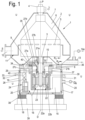
- Fig. 1 shows a separator arrangement 1 with a separator with a vertical axis of rotation D, which has a rotatable drum 2 which is placed on a rotatable drive spindle 3.
- the product supply of a product P that can be processed in continuous operation is preferably carried out from above through a supply pipe 4 (not shown in detail here).
- This structure is preferred.
- a hanging drum with a drive above the drum can also be implemented.
- the product to be processed is continuously fed into the drum, continuously centrifuged and at least one or all of the phases formed during the clarification and/or separation are also continuously removed. Liquid phase(s) is/are continuously drained away. Any solid phase that may also be formed can be discharged continuously through nozzles or non-continuously, for example with openings that can be closed by piston valves.
- the drum 2 is designed here to separate the product P to be processed into at least one liquid phase L or several liquid phases and a solid phase S. It points here like the drum of the EP 1 119 416 B1 or the counterpart used in practice preferably has a stack of separating plates inside (not visible here).
- the liquid phases L are drained from the drum 2 via liquid outlets, in particular peeling disks in the manner of a centripetal pump.
- the solids phase S is discharged either discontinuously at discontinuously closable solids discharge openings 5 in the drum shell or continuously through nozzles in the drum shell.
- the drum 2 is inserted into a hood space 6 that is sealed against the environment.
- This hood space 6 is delimited here by a hood 7, which is fixed to a foundation - here a machine frame 8 -, a cover 9 below the drum, which is fixed to the hood 7, and a spindle housing 10, which is penetrated by the drive spindle 3 , fixed.
- a solids catcher 11 is also formed in the hood 7, which serves to divert solids escaping from the drum from the hood space through a solids discharge line 12.
- a pump 14a (or another device for lowering the pressure in the hood space 6 relative to the environment) is also connected to a vacuum connection 13 to the hood space 6, with which a negative pressure relative to the environment U outside the hood space 6 can be generated in the hood space 6 .
- This vacuum connection 13 is preferably formed at a location which lies on a relatively large radius R p relative to the axis of rotation D, in particular on a radius which is equal to or larger than the largest radius R T of the drum 2.
- the energy consumption of the separator arrangement 1 is further reduced here in that not only the hood space 6, in which the drum 2 is arranged, but also a drive space 15, in which one or more components of a separator drive 16 are arranged , is designed to be sealed in such a way that a negative pressure, in particular a negative pressure of more than 0.2 bar, compared to the ambient pressure in the environment U can be generated in it with at least one further pump 14b or also with the pump 14a or during operation is produced.
- the drive chamber 15 is delimited here by a drive housing 17, which is in turn designed in a correspondingly sealed design in accordance with the task of generating a negative pressure in the drive chamber 15 relative to the environment U. This is what we are looking for Fig. 1 between elements of the drive housing 17, suitable seals 18 are formed.
- the pump 14b can be connected to a vacuum connection 20 of the drive chamber 15.
- One or more or even all elements of the separator drive 16 are accommodated in the drive chamber 15. Only the drive spindle 3 protrudes Fig. 1 from the drive compartment with its upper end into the hood compartment.
- the spindle bearing is preferably arranged entirely or partially - here both a neck bearing 21a and a foot bearing 21b - in the negative pressure area.
- a neck bearing 21a and a foot bearing 21b - in the negative pressure area.
- one (in particular the neck bearing 21a) or both bearings 21a, b do not belong to this negative pressure area.
- the spindle housing 10 is supported on the machine frame 8 in a flange area on elastic elements 40.
- the rotor 22a is attached here directly to the drive spindle 3 and the stator 22b is in a motor housing 23, which in turn is attached to the side of the machine frame 8 facing away from the hood space 6.
- a direct drive can preferably be accommodated in the drive space, although the electric drive motor 22 could also be arranged between the bearings 21a, b (the latter variant not shown here). It is also conceivable to accommodate the drive motor in the negative pressure area of the drive chamber 15, which is connected to the drive spindle 3 via a coupling (also not shown here).
- a lubrication system 24 is also arranged in the drive chamber 15, which serves to lubricate the spindle bearing 21 and/or to lubricate components on the engine.
- the lubrication system here has a lubricant circuit, which has the elements oil container 25, pump 26, supply line 27a, b to the spindle bearing 21, oil collecting container 28, which is connected to the spindle in a rotationally fixed manner and in which it is located on a radius during operation due to the cup-like design Oil level forms, a peeling element 29, which drains the oil in the collecting container, and a return line 27c, d into the oil container 25.
- all of these elements of the lubrication system are advantageously and compactly accommodated in the negative pressure area, i.e. in the drive room.
- Outflow and supply lines 30, 31, 32, 33 from one or more coolant circuits also open into the drive chamber, here once for the motor 22 and once for the lubrication system 24.
- One or more through openings 34, 35, 36, 37 are also formed in the machine frame, which ensure that, if possible, no pressure gradients arise within the drive chamber 15.
- hood space 6 and the drive space 15 are not sealed against each other.
- this is achieved by way of example and simply in that the cover 9 below the drum 2 is not sealed radially on the inside of the spindle housing 10, but rather that a gap 42 is formed between these elements, which ensures pressure equalization between the hood space 6 and the drive space 15. No sealing, e.g. no mechanical seal, is required.
- the suction takes place at a radius of the hood 7, which, based on the axis of rotation, lies on a radius that is greater than 80%, in particular more than 100%, of the largest drum radius.
- the support provided by the drum differential pressure effect is particularly advantageous.
- a vacuum connection on a solids container (not shown here) is also conceivable.
- the separator arrangement according to the type Fig. 1 also meets the highest energy saving requirements.
- the pump (14a) is designed to generate the substructure by suction on a large, in particular largest, diameter of the hood.
- the suction takes place at a diameter of the hood which, based on the axis of rotation, is at a larger radius than the largest drum radius.
- the support provided by the drum differential pressure effect is particularly advantageous.
Landscapes
- Centrifugal Separators (AREA)
- Rotary Pumps (AREA)
- Separation Using Semi-Permeable Membranes (AREA)
Description
- Die Erfindung betrifft eine Separatoranordnung nach dem Oberbegriff des Anspruchs 1.
- Für verschiedene Anwendungen von Separatoren, so insbesondere im Bereich der Medizin- oder Lebensmitteltechnik oder auf dem Gebiet der Milchverarbeitung werden Zentrifugentrommeln in einem Raum angeordnet und betrieben, der relativ zur Umgebung einen Unterdruck aufweist.
- Die in der gattungsgemäßen
EP 1 119 416 B1 dargestellte Separatoranordnung und ihr in der Praxis eingesetztes Pendant weisen eine Separatortrommel zur Flüssig-/Flüssig-/Fest-Trennung mit einer vertikalen Drehachse auf, welche in einem abgedichteten Behältnis bzw. Haubenraum angeordnet ist, in welchem mit einer Pumpe ein Unterdruck gegenüber der Umgebung erzeugt werden kann. Die Separatortrommel weist ein Zulaufrohr auf sowie eine oder mehrere Schälscheiben zum Austrag der einen oder mehreren Flüssigkeitsphase sowie Feststoffaustragsöffnungen zum kontinuierlichen oder intermittierenden Austrag von Feststoffen. - Eine Separatoranordnung gemäß dem Oberbegriff des Anspruchs 1 ist aus der
WO 2010/101524 A2 bekannt. Die gattungsgemäße Konstruktion und ihre Arbeitsweise haben sich an sich bewährt. Dennoch besteht ein Bedarf nach einer weiteren Verbesserung der bekannten Separatoranordnung und des Verfahrens zu ihrem Betrieb. - Die Erfindung löst diese Aufgabe durch den Gegenstand der Ansprüche 1 und 10. Es wird auch der Antriebsraum unter Unterdruck gegenüber der Umgebung gesetzt, insbesondere, um an rotierenden Teilen dieses Bereichs eine Energieersparnis zu erreichen.
- In dem Komponenten der Antriebseinrichtung - insbesondere Motor-, Kupplungs-, Spindel-, Lager- und/oder sonstige Antriebskomponenten - enthaltenden Raum wird dazu ganz oder jedenfalls in einem Teilbereich ein Unterdruck relativ zur Umgebung erzeugt.
- Hierzu ist der Antriebsraumbereich mit einer Pumpe oder einer sonstigen Unterdruck erzeugenden Einrichtung evakuierbar und/oder er ist mit dem (Hauben-)Raum, welcher die Trommel umgibt verbunden, so dass eine Pumpe bzw. eine entsprechende Einrichtung, welche ergänzend in diesem Raum ein Vakuum erzeugt, auch in dem Antriebsraum "mit" ein Vakuum erzeugen kann. Da auch der Haubenraum, in welchem die Trommel angeordnet ist, unter Unterdruck gegenüber der Umgebung gesetzt wird, ist zudem auch hier eine Energieersparnis zu erreichen. Ein Antriebsraum einer Laborzentrifuge unter Vakuum (die nicht kontinuierlich arbeitet) ist aus der
JP 2032 058359 W - Besonders vorteilhaft ist nach einer Variante ein Unterdruckanschluss auf besonders großem Radius im Haubenraum, da sich hier die Trommeldrehung unterstützend auf die Erzeugung des Vakuums auswirkt. Vorzugsweise sind dabei sowohl die Trommel als auch der Haubenraum abschnittsweise konisch ausgebildet.
- Eine Variante für einen Unterdruckanschluss kann ein Anschluss über eine Bohrung in der Spindel sein. In diesem Fall wird das freie Ende der Spindel unten durch die abgedichtete Gestellwandung geführt und über abgedichtete Anschlüsse erfolgt die Anbindung an ein Unterdrucksystem. Die Bohrung in der Spindel endet im Bereich unterhalb der Trommel im Haubenraum. Die Durchführung der Spindel durch die Gestellwandung ist ebenfalls mittels schleifenden Elementen abgedichtet.
- Als Flüssigkeitsabläufe in der Trommel eignen sich übliche Schälscheiben. Es ist aber auch eine Abdichtung/Isolierung der Greifer / Trommel mittels einer Tauchscheibe denkbar.
- Zum technologischen Hintergrund sei noch die nicht kontinuierlich nutzbare Laborzentrifuge der
JP 32 58 359 A - Besonders vorteilhaft ist ein Einsatz eines fluid-, insbesondere öl- oder wassergekühlten Motors.
- Vorteilhaft erscheint es, auch das Ölschmierungssystem, insbesondere ein Umlaufschmierungssystem im Vakuumbereich anzuordnen, insbesondere mit einem oder mehreren der folgenden Merkmale:
- Ölumlaufpumpe im Vakuumbereich
- Ölbehälter im Vakuumbereich,
- Wärmetauscher (für Ölkreislauf) im Vakuumbereich
- Vorteilhaft erscheint auch eine Kühlfluidzufuhr durch die Trommel (nach Art der
DE 19922237 ). - Besonders vorteilhaft ist zudem, wenn im Betrieb ein Unterdruck unter dem Atmosphärendurck, insbesondere 0,3 bar kleiner als dieser, vorzugsweise 0,4 bar kleiner als dieser, insbesondere 0,7 bar kleiner als dieser erzeugt wird.
- Es ist ferner vorteilhaft, wenn der Wert des Unterdruckes jedenfalls im Haubenraum mit der Trommel während des Betriebs abhängig vom Betriebszustand verändert wird. So kann beispielsweise zeitlich vor, bei oder nach einer Änderung des Betriebszustandes auch eine Änderung des Unterdruckes erfolgen. Dabei kann die Änderung des Betriebszustandes, die vor, bei oder nach der Änderung des Unterdruckes erfolgt, eine Feststoffentleerung sein. Beispielsweise kann der Unterdruck kurz vor oder zumindest während der Entleerung etwas erhöht werden (z.B. von 0,2 bar auf 0,5 bar) und nach der Entleerung wieder abgesenkt werden (z.B. wieder auf 0, 2bar), damit bei der Feststoffentleerung keine nachteiligen Effekte aufgrund des hohen Unterdruckes auftreten.
- Nach einer weiteren vorteilhaften Variante kann beispielsweise die Änderung des Betriebszustandes, vor, bei oder nach der Änderung des Unterdruckes erfolgt, eine Anlauf- oder Abfahr-/Auslaufphase sein.
- Besonders geeignet ist die Erfindung für eine Separatoranordnung mit einem Separator mit einer Trommel mit vertikaler Drehachse, die auf eine drehbare Spindel aufgesetzt und von einer Haube umgeben ist, wobei die Trommeln einen Trommeldurchmesser größer 500 mm, insbesondere 800 mm, ganz besonders bevorzugt größer 900 mm und/oder Drehzahlen z.B. größer 8000 U/min, 5000 U/min, 4000 U/min im Betrieb aufweisen.
- Vorzugsweise beträgt die die Umfangsgeschwindigkeit am Trommelaußendurchmesser wenigstens 100 m/s oder mehr.
- Die Oberfläche der Trommel beträgt ferner vorzugsweise 0,5m2 bis 5m2, insbesondere 1-3,5 m2, damit sich die Wirkung der Unterstützung der Unterdruckerzeugung besonders vorteilhaft auswirkt.
- Weitere vorteilhafte Ausgestaltungen sind in den übrigen Unteransprüchen angegeben.
- Nachfolgend wird die Erfindung unter Bezug auf die Zeichnung anhand eines Ausführungsbeispiels näher beschrieben. Es zeigen:
- Fig. 1
- eine schematische Darstellung einer ersten erfindungsgemäßen Separatoranordnung mit einem im Schnitt dargestellten Antriebsraum;
- Fig. 2
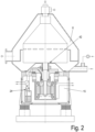
- eine schematische Darstellung einer zweiten erfindungsgemäßen Separatoranordnung mit einem im Schnitt dargestellten Antriebsraum; und
- Fig. 3
- eine schematische Darstellung einer dritten erfindungsgemäßen Separatoranordnung mit einem im Schnitt dargestellten Antriebsraum;
-
Fig. 1 zeigt eine Separatoranordnung 1 mit einem Separator mit vertikaler Drehachse D, der eine drehbare Trommel 2 aufweist, die auf eine drehbare Antriebsspindel 3 aufgesetzt ist. Die Produktzuleitung eines im kontinuierlichen Betrieb verarbeitbaren Produktes P erfolgt vorzugsweise von oben durch ein Zuleitungsrohr 4 (hier nicht detailliert dargestellt). Dieser Aufbau wird bevorzugt. Es ist aber auch eine hängende Trommel mit einem Antrieb oberhalb der Trommel realisierbar. - Bei der Verarbeitung im kontinuierlichen Betrieb wird das zu verarbeitende Produkt kontinuierlich in die Trommel geleitet bzw. zugeführt, kontinuierlich zentrifugiert und wenigstens eine oder sämtliche der bei der Klärung und/oder Trennung gebildeten Phasen wird/werden auch kontinuierlich abgeleitet. Flüssigkeitsphase(n) wird/werden kontinuierlich abgeleitet. Eine ggf. auch gebildete Feststoffphase kann kontinuierlich durch Düsen oder nicht kontinuierlich beispielsweise mit von Kolbenschiebern verschließbaren Öffnungen ausgetragen werden.
- Die Trommel 2 ist hier dazu ausgelegt, das zu verarbeitende Produkt P in wenigstens eine Flüssigkeitsphase L oder mehrere Flüssigkeitsphasen sowie eine Feststoffphase S zu trennen. Sie weist hier wie die Trommel der
EP 1 119 416 B1 bzw. das in der Praxis eingesetzte Pendant im Inneren vorzugsweise einen Trenntellerstapel aus Trenntellern auf (hier nicht zu erkennen). - Die Flüssigkeitsphasen L werden über Flüssigkeitsauslässe, insbesondere Schälscheiben nach Art einer Zentripetalpumpe, aus der Trommel 2 abgeleitet. Die Ableitung der Feststoffphase S erfolgt dagegen entweder diskontinuierlich an diskontinuierlich verschließbaren Feststoffaustragsöffnungen 5 im Trommelmantel oder kontinuierlich durch Düsen im Trommelmantel.
- Vorteilhaft erscheint der Einsatz insbesondere eines flüssigkeitsgesteuerten Kolbenschiebers.
- Die Trommel 2 ist in einen gegen die Umgebung abgedichtet ausgebildeten Haubenraum 6 eingesetzt.
- Dieser Haubenraum 6 wird hier von einer Haube 7, die an einem Fundament - hier einem Maschinengestell 8 - festgelegt ist, einer Abdeckung 9 unterhalb der Trommel, die an der Haube 7 festgelegt ist sowie einem Spindelgehäuse 10 begrenzt, welches von der Antriebsspindel 3 durchsetzt ist, festgelegt.
- Dabei sind vorzugsweise zwischen aneinander grenzende Elemente wie zwischen die Haube 7 und das Maschinengestell 8 sowie zwischen die Abdeckung 9 und die Haube 7 sowie zwischen die Abdeckung 9 und das Spindelgehäuse 10 und zwischen dem Spindelgehäuse (fest) und die Antriebsspindel 3 (die sich im Betrieb dreht) geeignete Dichtungen angeordnet, um eine abgedichtete Bauweise zu realisieren.
- In der Haube 7 ist ferner ein Feststofffänger 11 ausgebildet, welcher dazu dient, aus der Trommel austrende Feststoffe aus dem Haubenraum durch eine Feststoffableitung 12 abzuleiten.
- An den Haubenraum 6 ist ferner an einem Unterdruckanschluss 13 eine Pumpe 14a (oder eine sonstige Einrichtung zum Senken des Druckes in dem Haubenraum 6 gegenüber der Umgebung) angeschlossen, mit welcher in dem Haubenraum 6 ein Unterdruck gegenüber der Umgebung U außerhalb des Haubenraumes 6 erzeugbar ist.
- Vorzugsweise ist dieser Unterdruckanschluss 13 an einer Stelle ausgebildet, welche relativ zur Drehachse D auf einem relativ großen Radius Rp liegt, insbesondere auf einem Radius, der gleich oder größer ist als der größte Radius RT der Trommel 2.
- Durch den Betrieb bei Unterdruck, insbesondere bei einem Unterdruck, der mehr als 0,2 bar niedriger ist als der Umgebungsdruck in der Umgebung U, kann der Energieverbauch zum Antrieb der Trommel 2 gesenkt werden. Dies ist an sich allerdings bereits bekannt, so aus dem eingangs genannten Stand der Technik.
- Gegenüber dem Stand der Technik wird der Energieverbrauch der Separatoranordnung 1 hier sodann nochmals dadurch weiter gesenkt, dass nicht nur der Haubenraum 6, in welchem die Trommel 2 angeordnet ist, sondern auch ein Antriebsraum 15, in welchem eine oder mehrere Komponenten eines Separatorantriebs 16 angeordnet sind, so abgedichtet ausgelegt ist, dass in ihm wiederum mit wenigstens einer weiteren Pumpe 14b oder ebenfalls mit der Pumpe 14a ein Unterdruck, insbesondere ein Unterdruck von mehr als 0,2 bar, gegenüber dem Umgebungsdruck in der Umgebung U erzeugt werden kann bzw. im Betrieb erzeugt wird.
- Der Antriebsraum 15 wird hier einer Antriebsumhausung 17 begrenzt, die entsprechend der Aufgabe, in dem Antriebsraum 15 einen Unterdruck gegenüber der Umgebung U zu erzeugen, wiederum in entsprechend abgedichteter Bauart ausgeführt ist. Dazu sind nach
Fig. 1 zwischen Elementen der Antriebsumhausung 17 wiederum geeignete Dichtungen 18 ausgebildet. - Hier wird der Antriebsraum 15 von dem Maschinengestell 8 sowie Verschlussplatten 19 umgrenzt, die Öffnungen des Maschinengestells verschließen. Nach oben hin wird er von der Abdeckung 9 unterhalb der Trommel 2 und dem ein- oder mehrteiligen Spindelgehäuse 10 begrenzt.
- Die Pumpe 14b ist an einen Unterdruckanschluss 20 des Antriebsraumes 15 anschließbar.
- Im Antriebsraum 15 sind eines oder mehrere oder sogar sämtliche Elemente des Separatorantriebs 16 untergebracht. Lediglich die Antriebsspindel 3 ragt nach
Fig. 1 aus dem Antriebsraum heraus mit ihrem oberen Ende in den Haubenraum. - Vorzugsweise ist die Spindellagerung ganz oder teilweise - hier sowohl ein Halslager 21a als auch ein Fußlager 21b - im Unterdruckbereich angeordnet. Es ist aber auch denkbar, dass eines (insbesondere das Halslager 21a) oder beide Lager 21a, b nicht zu diesem Unterdruckbereich gehören.
- Das Spindelgehäuse 10 liegt in einem Flanschbereich an elastischen Elementen 40 abgestützt auf dem Maschinengestell 8 auf.
- Ebenfalls bevorzugt im Unterdruckbereich angeordnet ist der Antriebsmotor 22 angeordnet, der hier direkt in axialer Verlängerung der Antriebspindel 3 ausgebildet ist, so dass ein sogenannter Direktantrieb für die Trommel 2 gebildet wird.
- Der Rotor 22a ist hier direkt an der Antriebsspindel 3 befestigt und der Stator 22b ist im einem Motorgehäuse 23, welches wiederum an der von dem Haubenraum 6 abgewandten Seite des Maschinengestells 8 befestigt ist. Gerade ein solcher Direktantrieb ist bevorzugt im Antriebsraum unterbringbar, wobei der elektrische Antriebsmotor 22 aber auch zwischen den Lagern 21a, b angeordnet sein könnte (letztere Variante hier nicht dargestellt). Es ist ferner auch denkbar, den Antriebsmotor im Unterdruckbereich des Antriebsraums 15 unterzubringen, der über eine Kupplung mit der Antriebsspindel 3 verbunden ist (hier ebenfalls nicht dargestellt).
- Im Antriebsraum 15 ist zudem ein Schmierungssystem 24 angeordnet, welches zur Schmierung der Spindellagerung 21 und/oder zur Schmierung von Komponenten am Motor dient.
- Das Schmierungssystem weist hier einen Schmiermittelkreislauf auf, welcher die Elemente Ölbehälter 25, Pumpe 26, Zuleitung 27a, b zu der Spindellagerung 21, Ölauffangbehälter 28, der drehfest mit der Spindel verbunden ist und in dem sich im Betrieb aufgrund der topfartigen Gestaltung auf einem Radius ein Ölpegel ausbildet, ein Schälorgan 29, welches das Öl im Auffangbehälter ableitet, sowie eine Rückleitung 27c, d in den Ölbehälter 25 aufweist. Hier sind all diese Elemente des Schmierungssystems vorteilhaft und kompakt in dem Unterdruckbereich, d.h. im Antriebsraum, untergebracht.
- In den Antriebsraum münden hier ferner Ab- und Zuleitungen 30, 31, 32, 33 von einem oder mehreren Kühlmittelkreisläufen, hier einmal für den Motor 22 sowie einmal für das Schmierungssystem 24.
- Im Maschinengestell sind ferner eine oder mehrere Durchgangsöffnungen 34, 35, 36, 37 ausgebildet, welche dafür sorgen, dass innerhalb des Antriebsraums 15 möglichst keine Druckgradienten entstehen.
- Da im Antriebsraum 15 relativ zur Umgebung ebenfalls ein Unterdruck erzeugt wird, kann auch an den sich drehenden Teilen im Antriebsraum eine weitere Energieersparnis im Betrieb erreicht werden.
- Zu erwähnen ist noch, dass der gesamte Separator bzw. das Maschinengestell an elastischen Fußelementen 38 auf einem Fundamt 39 abgestützt ist.
- Nach
Fig. 2 sind der Haubenraum 6 und der Antriebsraum 15 nicht gegeneinander abgedichtet. Hier wird das beispielhaft und einfach dadurch erreicht, dass die Abdeckung 9 unterhalb der Trommel 2 nicht radial innen zum Spindelgehäuse 10 abgedichtet ist sondern dass zwischen diesen Elementen ein Spalt 42 ausgebildet ist, der für einen Druckausgleich zwischen dem Haubenraum 6 und dem Antriebsraum 15 sorgt. Hierbei wird keine Abdichtung, z.B. keine Gleitringdichtung benötigt. - Derart kann ggf. sogar mit nur einer einzigen Pumpe 14a der Unterdruck in beiden Räumen 6, 15 gleichzeitig erzeugt werden. Es können aber auch mehrere Pumpen vorgesehen sein.
- Insgesamt ist auch nach
Fig. 2 sowohl der Bereich innerhalb der Haube 7 mitsamt dem Antriebsraum 15 mit einer oder mehreren insbesondere auch drehbare Antriebskomponenten enthaltend, gegenüber der Umgebung U der Haube 7 so abgedichtet, das es möglich ist, diesen Bereich mit einer Pumpe 14a, b, die Luft/Gas aus dem Bereich zwischen der Haube 7 und der Trommel 2 und/oder dem Antriebsraum 15 pumpen kann, unter Unterdruck relativ zur Umgebung U zu setzen. - Die gesamte Energie des Motors und die Ölversorgung des Antriebes (Motors) erfolgt auch nach
Fig. 2 im geschlossenen Antriebsraum 15. - Nach
Fig. 3 ist dagegen keine Umlaufschmierung bzw. kein Schmiermittelkreislauf innerhalb des Antriebsraumes 15 angeordnet. Die Schmierölzu-und Abfuhr erfolgt in diesem Fall über ein extern (außerhalb des Antriebsraumes) installiertes Schmierölaggregat (hier nicht dargestellt). - Sämtliche Separatoranordnung der
Fig. 1 bis 3 werden auch höchsten Energieeinsparungsanforderungen gerecht. - Als besonders vorteilhaft ist nochmals zu betonen, dass in
Fig. 1 - 3 jeweils die Pumpe 14a zur Erzeugung des Unterstrucks durch Absaugung auf großem, insbesondere größtem Radius/Durchmesser der Haube 7 angeordnet ist. - Es erfolgt die Absaugung an einem Radius der Haube 7, der bezogen auf die Drehachse auf einem Radius liegt, der größer ist als 80%, insbesondere mehr als 100%, des größten Trommelradius. Vorteilhaft wirkt sich dabei insbesondere die Unterstützung durch die Trommel-Differenzdruckwirkung aus.
- Denkbar ist auch ein Unterdruckanschluss an einem (hier nicht dargestellten) Feststoffbehälter.
- Ebenfalls vorteilhaft ist ein weiterer Unterdruckanschluss im Steuerwasser-Ablaufbereich unterhalb der Trommel (hier nicht dargestellt).
- Ebenfalls vorteilhaft und baulich einfach wäre ein weiterer Unterdruckanschluss durch die Spindel 3 in den Antriebsraum 15 (z.B. eine Bohrung bei Maschinen mit externem Ölaggregat).
- Weiter vorteilhaft ist eine abgedichtete/isolierte Ausgestaltung der Schälscheiben mittels einer Tauchscheibe. Weiter vorteilhaft ist ein Einsatz einer hermetischen Greifer / Pumpenkombination (nicht dargestellt).
- Besonders vorteilhaft ist ein Einsatz eines fluid-, insbesondere öl- oder wasssergekühlten Motors, da durch den Unterdruck im Antriebsraum die Kühlwirkung durch Luft verringert wird.
- Die Separatoranordnung nach Art der
Fig. 1 wird auch höchsten Energieeinsparungsanforderungen gerecht. - Vorteilhaft ist auch, das in
Fig. 1 die Pumpe (14a) zur Erzeugung des Unterstrucks durch Absaugung auf großem, insbesondere größtem Durchmesser der Haube ausgelegt ist. Insbesondere erfolgt die Absaugung an einem Durchmesser der Haube, der bezogen auf die Drehachse auf einem größeren Radius liegt als der größte Trommelradius. Vorteilhaft wirkt sich dabei insbesondere die Unterstützung durch die Trommel-Differenzdruckwirkung aus. - Ebenfalls vorteilhaft ist ein oder ein weiterer Unterdruckanschluss an der Pumpe 14b 14b im Antriebsraum oder auf einem (hier nicht dargestellten Feststoffbehälter im Zentrum mit einem "Verlängerungsrohr" großen Durchmessers zur "Sauberhaltung des Unterdruckanschlusses.
- Ebenfalls vorteilhaft ist ein oder ein weiterer Unterdruckanschluss an der Pumpe 14b im Antriebsraum oder auf einem Anschluss im Steuerwasser-Ablaufbereich unterhalb der Trommel (ebenfalls nicht dargestellt).
-
Bezugszeichen Separatoranordnung 1 Drehachse D Trommel 2 Antriebsspindel 3 Produkt P Zuleitungsrohr 4 Flüssigkeitsphasen L, L1, L2 Feststoffaustragsöffnungen 5 Haubenraum 6 Haube 7 Maschinengestell 8 Abdeckung 9 Spindelgehäuse 10 Feststofffänger 11 Ableitung 12 Anschluss 13 Pumpe 14a, b Umgebung U Radius Rp, RT Antriebsraum 15 Separatorantrieb 16 Antriebsumhausung 17 Dichtungen 18 Verschlussplatten 19 Anschluss 20 Halslager 21a Fußlager 21b Antriebsmotor 22 Rotor 22a Stator 22b Schmierungssystem 24 Ölbehälter 25 Pumpe 26 Zuleitung 27 Ölauffangbehälter 28 Schälorgan 29 Ab- und Zuleitungen 30, 31, 32, 33 Durchgangsöffnungen 34, 35, 36, 37 Fußelemente 38 Fundamt 39 Elastische Elemente 40 Spalt 42
Claims (12)
- Separatoranordnung zur Verarbeitung eines Produktes im kontinuierlichen Betrieb, mit:a) einer in einem Haubenraum (6) angeordneten drehbaren Trommel (1) mit vertikaler Drehachse (D), die auf eine drehbare Antriebsspindel (3) aufgesetzt ist,b) einem Antriebsraum (15), der eine, mehrere oder sämtliche Komponenten eines Separatorantriebs (23) enthält,c) einer Ableitung eines Feststofffängers (11),d) einem Unterdruckanschluss (13) am oder im Haubenraum (6),e) wobei der Haubenraum (6) gegenüber der Umgebung (U) abgedichtet ausgebildet ist und wobei mit einer oder der Unterdruck erzeugenden Einrichtung, insbesondere einer Pumpe (14a), im Betrieb ein Unterdruck im Haubenraum (6) gegenüber der Umgebung (U) außerhalb des Haubenraums (6) erzeugbar ist,
gekennzeichnet durchf) eine Feststoffrinne, wobeig) der Unterdruckanschluss (13) unterhalb der Feststoffrinne und der Ableitung (12) eines Feststofffängers (11) ausgebildet ist, wobei der am/im Haubenraum (6) ausgebildete Unterdruckanschluss auf einem Radius der Haube (7) relativ zur Drehachse (D) der Trommel (2) liegt, der größer ist als 80% des maximalen Radius der Trommel (2), undh) eine abgedichtete Bauweise des Antriebsraumes (15), und wenigstens eine Unterdruck erzeugende Einrichtung, insbesondere eine Pumpe (14a, b), zur Erzeugung von Unterdruck im abgedichteten Antriebsraum (15) gegenüber der Umgebung (U) außerhalb des Antriebsraums (15). - Separatoranordnung nach Anspruch 1, dadurch gekennzeichnet, dass der Haubenraum (6) und der Antriebsraum (17) relativ zueiander abgedichtet sind, so dass in ihnen im Betrieb ein unterschiedlicher Druck herrschen kann.
- Separatoranordnung nach Anspruch 1, dadurch gekennzeichnet, dass zwischen dem Haubenraum (6) und dem Antriebsraum (15) miteinander wenigstens eine Verbindung ausgebildet ist, um einen Druckausgleich zwischen diesen Räumen (6, 15) zu schaffen.
- Separatoranordnung nach einem der vorstehenden Ansprüche, dadurch gekennzeichnet, dass der Unterdruckanschluss auf einem Radius der Haube (7) relativ zur Drehachse (D) der Trommel (2) liegt, der größer ist als 100% des maximalen Radius der Trommel (2)
- Separatoranordnung nach einem der vorstehenden Ansprüche, dadurch gekennzeichnet, dass die Haube (7) und die Trommel (2) im vertikal oberen Bereich eine konische Form aufweisen.
- Separatoranordnung nach einem der vorstehenden Ansprüche, dadurch gekennzeichnet, dass die Trommel (2) eine oder mehrere Schälscheiben als Flüssigkeitsauslaß aufweist und dass sie vorzugsweise ferner kontinuierlich oder diskontinuierlich Feststoff austragende Feststoffaustragsöffnungen aufweist.
- Separatoranordnung nach einem der vorstehenden Ansprüche, dadurch gekennzeichnet, dass im unter Unterdruck setzbaren Antriebsraum (15) wenigstens eine, mehrere oder sämtliche Komponente(n) eines Ölschmierungssystem, insbesondere ein Umlaufschmierungssystems angeordnet ist/sind.
- Separatoranordnung nach einem der vorstehenden Ansprüche, dadurch gekennzeichnet, dass im unter Unterdruck setzbaren Antriebsraum (15) ein Antriebsmotor (22) angeordnet ist.
- Separatoranordnung nach Anspruch 8, dadurch gekennzeichnet, dass der Antriebsmotor flüssigkeitsgekühlt ausgebildet ist.
- Verfahren zum Betreiben eines Separators nach einem der vorstehenden Ansprüche, dadurch gekennzeichnet, dass der Unterdruck im Haubenraum (6) während des Betriebs verändert wird.
- Verfahren nach Anspruch 10, dadurch gekennzeichnet, dass der Unterdruck im Haubenraum (6) während des Betriebs in Abhängigkeit von dem aktuellen oder zu erwartenden Betriebszustand verändert wird.
- Verfahren nach einem der vorstehenden Ansprüche 10 oder 11, dadurch gekennzeichnet, dass der Druck im Haubenraum vor Feststoff-Entleerungen erhöht wird.
Priority Applications (1)
| Application Number | Priority Date | Filing Date | Title |
|---|---|---|---|
| PL13714233T PL2830777T3 (pl) | 2012-03-26 | 2013-03-22 | Układ separatora |
Applications Claiming Priority (3)
| Application Number | Priority Date | Filing Date | Title |
|---|---|---|---|
| DE102012102593 | 2012-03-26 | ||
| DE102013100180.7A DE102013100180B4 (de) | 2012-03-26 | 2013-01-09 | Separatoranordnung |
| PCT/EP2013/056015 WO2013143985A2 (de) | 2012-03-26 | 2013-03-22 | Separatoranordnung |
Publications (3)
| Publication Number | Publication Date |
|---|---|
| EP2830777A2 EP2830777A2 (de) | 2015-02-04 |
| EP2830777B1 EP2830777B1 (de) | 2018-04-25 |
| EP2830777B2 true EP2830777B2 (de) | 2024-01-10 |
Family
ID=49112330
Family Applications (1)
| Application Number | Title | Priority Date | Filing Date |
|---|---|---|---|
| EP13714233.7A Active EP2830777B2 (de) | 2012-03-26 | 2013-03-22 | Separatoranordnung |
Country Status (12)
| Country | Link |
|---|---|
| US (1) | US10105717B2 (de) |
| EP (1) | EP2830777B2 (de) |
| CN (1) | CN104271249B (de) |
| AU (1) | AU2013242071B2 (de) |
| BR (1) | BR112014023659B1 (de) |
| DE (1) | DE102013100180B4 (de) |
| DK (1) | DK2830777T3 (de) |
| NZ (1) | NZ700141A (de) |
| PL (1) | PL2830777T3 (de) |
| RU (1) | RU2622946C2 (de) |
| TR (1) | TR201809513T4 (de) |
| WO (1) | WO2013143985A2 (de) |
Families Citing this family (14)
| Publication number | Priority date | Publication date | Assignee | Title |
|---|---|---|---|---|
| DE102009022972A1 (de) * | 2009-05-28 | 2010-12-02 | Gea Westfalia Separator Gmbh | Zentrifuge mit einem Schmiermittelsystem |
| DE102013100180B4 (de) | 2012-03-26 | 2025-05-15 | Gea Mechanical Equipment Gmbh | Separatoranordnung |
| DE102012110846A1 (de) * | 2012-11-12 | 2014-05-15 | Gea Mechanical Equipment Gmbh | Separator mit Direktantrieb |
| CN105107638A (zh) * | 2015-08-27 | 2015-12-02 | 张家港市中南化工机械有限公司 | 一种卧式刮刀卸料离心机 |
| RU2631951C1 (ru) * | 2017-01-19 | 2017-09-29 | Федеральное казенное предприятие "Научно-исследовательский институт "Геодезия" (ФКП "НИИ "Геодезия") | Вакуумная центрифуга |
| DE102017114649A1 (de) | 2017-06-30 | 2019-01-03 | Gea Mechanical Equipment Gmbh | Separator mit Direktantrieb |
| US11596955B2 (en) * | 2017-12-22 | 2023-03-07 | Tetra Laval Holdings & Finance S.A. | Centrifugal separator for separating a liquid mixture, and method therefor |
| DE102018108471A1 (de) * | 2018-04-10 | 2019-10-10 | Gea Mechanical Equipment Gmbh | Verfahren, mit dem ein Schmiermitteldurchfluss an einer Zentrifuge überwacht wird |
| DE102018131956A1 (de) | 2018-12-12 | 2020-06-18 | Gea Mechanical Equipment Gmbh | Separator und Verfahren zu dessen Betrieb |
| DE102020111217A1 (de) * | 2020-04-24 | 2021-10-28 | Gea Mechanical Equipment Gmbh | Separator mit Direktantrieb |
| CN112170023B (zh) * | 2020-09-18 | 2022-05-27 | 中国人民解放军陆军军医大学第二附属医院 | 一种离心机 |
| EP4094839B1 (de) * | 2021-05-28 | 2024-01-31 | Alfa Laval Corporate AB | Zentrifugalabscheider |
| EP4450165B1 (de) * | 2023-04-18 | 2025-10-15 | Alfa Laval Corporate AB | Zentrifugalabscheider |
| CN116764824B (zh) * | 2023-08-25 | 2023-11-07 | 山东万佳食品有限公司 | 一种味精生产用离心机 |
Family Cites Families (21)
| Publication number | Priority date | Publication date | Assignee | Title |
|---|---|---|---|---|
| US4205779A (en) * | 1979-03-14 | 1980-06-03 | Beckman Instruments, Inc. | Pressure bypass ports for an ultracentrifuge drive system in a vacuum environment |
| DE3523907A1 (de) * | 1985-07-04 | 1987-01-15 | Westfalia Separator Ag | Verfahren und vorrichtung zur zentrifugalen reinigung von gebrauchten mineraloelen |
| US4941866A (en) * | 1986-11-20 | 1990-07-17 | Gorodissky Boris P | Centrifuge |
| SU1704839A1 (ru) * | 1988-07-18 | 1992-01-15 | Московское научно-производственное объединение "Биофизприбор" | Привод ультрацентрифуги |
| DE3924372C1 (de) | 1989-07-22 | 1990-11-22 | Westfalia Separator Ag, 4740 Oelde, De | |
| JP2600957B2 (ja) * | 1990-03-09 | 1997-04-16 | 日立工機株式会社 | 遠心機の排気構造 |
| RU2041742C1 (ru) * | 1992-04-07 | 1995-08-20 | Научно-исследовательский институт прикладной математики и кибернетики при Нижегородском государственном университете им.Н.И.Лобачевского | Ультрацентрифуга |
| DE19846535C2 (de) * | 1998-10-09 | 2000-12-07 | Westfalia Separator Ag | Zentrifuge |
| DE19922237C2 (de) * | 1999-05-14 | 2003-01-02 | Westfalia Separator Ag | Zentrifuge |
| US6440316B1 (en) * | 2000-03-21 | 2002-08-27 | Virginia Tech Intellectual Properties, Inc. | Methods of improving centrifugal filtration |
| JP3772640B2 (ja) * | 2000-05-19 | 2006-05-10 | 日立工機株式会社 | 遠心機 |
| DE10212808B4 (de) * | 2002-03-22 | 2004-07-29 | Westfalia Separator Ag | Separator |
| DE20307913U1 (de) * | 2003-05-19 | 2003-09-04 | Martin Christ Gefriertrocknungsanlagen GmbH, 37520 Osterode | Vorrichtung zur Konzentration von Stoffgemischen |
| DE102006020467A1 (de) * | 2006-04-28 | 2007-10-31 | Westfalia Separator Ag | Separator mit Direktantrieb |
| CN101896281B (zh) * | 2007-12-13 | 2013-12-04 | Gea韦斯伐里亚分离机有限公司 | 具有用于短轴驱动装置的润滑系统的分离器 |
| DE102008062055B4 (de) | 2008-12-12 | 2021-07-22 | Gea Mechanical Equipment Gmbh | Verfahren zur Überwachung der automatisierten Entleerung einer Zentrifuge |
| SE533562C2 (sv) * | 2009-03-06 | 2010-10-26 | Alfa Laval Corp Ab | Centrifugalseparator |
| DE102010038193A1 (de) * | 2010-10-14 | 2012-04-19 | Gea Mechanical Equipment Gmbh | Verfahren zur Phasentrennung eines Produktes mit einer Zentrifuge |
| DE102011107158A1 (de) * | 2011-07-14 | 2013-01-17 | Gea Mechanical Equipment Gmbh | Zentrifuge |
| DE102013100180B4 (de) | 2012-03-26 | 2025-05-15 | Gea Mechanical Equipment Gmbh | Separatoranordnung |
| DE102012110846A1 (de) * | 2012-11-12 | 2014-05-15 | Gea Mechanical Equipment Gmbh | Separator mit Direktantrieb |
-
2013
- 2013-01-09 DE DE102013100180.7A patent/DE102013100180B4/de active Active
- 2013-03-22 CN CN201380022728.8A patent/CN104271249B/zh active Active
- 2013-03-22 WO PCT/EP2013/056015 patent/WO2013143985A2/de not_active Ceased
- 2013-03-22 NZ NZ700141A patent/NZ700141A/en unknown
- 2013-03-22 DK DK13714233.7T patent/DK2830777T3/en active
- 2013-03-22 BR BR112014023659-3A patent/BR112014023659B1/pt active IP Right Grant
- 2013-03-22 RU RU2014142175A patent/RU2622946C2/ru active
- 2013-03-22 TR TR2018/09513T patent/TR201809513T4/tr unknown
- 2013-03-22 EP EP13714233.7A patent/EP2830777B2/de active Active
- 2013-03-22 AU AU2013242071A patent/AU2013242071B2/en active Active
- 2013-03-22 PL PL13714233T patent/PL2830777T3/pl unknown
- 2013-03-22 US US14/388,118 patent/US10105717B2/en active Active
Non-Patent Citations (1)
| Title |
|---|
| siehe anhang † |
Also Published As
| Publication number | Publication date |
|---|---|
| US10105717B2 (en) | 2018-10-23 |
| AU2013242071B2 (en) | 2017-07-06 |
| DE102013100180A1 (de) | 2013-09-26 |
| EP2830777A2 (de) | 2015-02-04 |
| NZ700141A (en) | 2016-07-29 |
| WO2013143985A2 (de) | 2013-10-03 |
| RU2014142175A (ru) | 2016-05-20 |
| BR112014023659B1 (pt) | 2020-06-30 |
| CN104271249B (zh) | 2016-07-06 |
| TR201809513T4 (tr) | 2018-07-23 |
| DE102013100180B4 (de) | 2025-05-15 |
| RU2622946C2 (ru) | 2017-06-21 |
| WO2013143985A3 (de) | 2014-06-26 |
| DK2830777T3 (en) | 2018-07-23 |
| US20150051059A1 (en) | 2015-02-19 |
| CN104271249A (zh) | 2015-01-07 |
| AU2013242071A1 (en) | 2014-10-09 |
| PL2830777T3 (pl) | 2018-09-28 |
| EP2830777B1 (de) | 2018-04-25 |
Similar Documents
| Publication | Publication Date | Title |
|---|---|---|
| EP2830777B2 (de) | Separatoranordnung | |
| EP1996335B1 (de) | Separatoranordnung in sanitärer ausführung | |
| EP2916961B1 (de) | Separator mit direktantrieb | |
| EP2874752B1 (de) | Separatoranordnung | |
| DE102012203697A1 (de) | Elektrische Maschine mit einem Rotor zur Kühlung der elektrischen Maschine | |
| EP2923119A1 (de) | Adapterbaugruppe | |
| DE102019206333B4 (de) | Hydraulikaggregat | |
| EP3417943A1 (de) | Zentrifugenrotor mit abdichtung | |
| WO2009074456A1 (de) | Separator mit einem schmiermittelsystem für einen kurzspindelantrieb | |
| DE102014114837A1 (de) | Kältemittelverdichter | |
| DE102011079555B4 (de) | Antriebsanordnung für eine Vertikal-Rollenmühle | |
| EP4196282B1 (de) | Separatoreinsatz und separator | |
| DE602004001156T2 (de) | Verdichtereinheit mit unterstützter Kühlung | |
| EP4146370B1 (de) | Zentrifugalabscheider | |
| EP3438460B1 (de) | Vakuumpumpe | |
| DE202016106867U1 (de) | Ölabscheider mit Wellenlagerung zwischen Antriebs- und Abscheidekammer | |
| EP1913676A1 (de) | Kühlmittelpumpe für elektromotore | |
| EP2852466A2 (de) | Antriebsvorrichtung für eine separatoranordnung | |
| EP2772310A2 (de) | Verfahren zur Verarbeitung brennbarer Produkte mit einer Separatoranordnung | |
| EP2187505A2 (de) | Elektromotor für Flaschenverschließer | |
| DE102007016425A1 (de) | Ölabscheider für CO2-Kälteanlagen | |
| WO2014009518A1 (de) | Vertikale welle mit gleitlager für eine turbine oder einen generator | |
| DE102015113821A1 (de) | Vakuumpumpe | |
| DE102015110996B4 (de) | Gargerät mit Lüfterrad | |
| DE102010009638A1 (de) | Gaszentrifuge ohne externe Gasförderpumpe für die Gaszufuhr |
Legal Events
| Date | Code | Title | Description |
|---|---|---|---|
| PUAI | Public reference made under article 153(3) epc to a published international application that has entered the european phase |
Free format text: ORIGINAL CODE: 0009012 |
|
| 17P | Request for examination filed |
Effective date: 20141007 |
|
| AK | Designated contracting states |
Kind code of ref document: A2 Designated state(s): AL AT BE BG CH CY CZ DE DK EE ES FI FR GB GR HR HU IE IS IT LI LT LU LV MC MK MT NL NO PL PT RO RS SE SI SK SM TR |
|
| AX | Request for extension of the european patent |
Extension state: BA ME |
|
| DAX | Request for extension of the european patent (deleted) | ||
| GRAP | Despatch of communication of intention to grant a patent |
Free format text: ORIGINAL CODE: EPIDOSNIGR1 |
|
| STAA | Information on the status of an ep patent application or granted ep patent |
Free format text: STATUS: GRANT OF PATENT IS INTENDED |
|
| INTG | Intention to grant announced |
Effective date: 20171129 |
|
| GRAA | (expected) grant |
Free format text: ORIGINAL CODE: 0009210 |
|
| GRAS | Grant fee paid |
Free format text: ORIGINAL CODE: EPIDOSNIGR3 |
|
| STAA | Information on the status of an ep patent application or granted ep patent |
Free format text: STATUS: THE PATENT HAS BEEN GRANTED |
|
| AK | Designated contracting states |
Kind code of ref document: B1 Designated state(s): AL AT BE BG CH CY CZ DE DK EE ES FI FR GB GR HR HU IE IS IT LI LT LU LV MC MK MT NL NO PL PT RO RS SE SI SK SM TR |
|
| REG | Reference to a national code |
Ref country code: GB Ref legal event code: FG4D Free format text: NOT ENGLISH |
|
| REG | Reference to a national code |
Ref country code: CH Ref legal event code: EP |
|
| REG | Reference to a national code |
Ref country code: AT Ref legal event code: REF Ref document number: 992312 Country of ref document: AT Kind code of ref document: T Effective date: 20180515 |
|
| REG | Reference to a national code |
Ref country code: IE Ref legal event code: FG4D Free format text: LANGUAGE OF EP DOCUMENT: GERMAN |
|
| REG | Reference to a national code |
Ref country code: DE Ref legal event code: R096 Ref document number: 502013010011 Country of ref document: DE |
|
| REG | Reference to a national code |
Ref country code: NL Ref legal event code: FP |
|
| REG | Reference to a national code |
Ref country code: DK Ref legal event code: T3 Effective date: 20180716 |
|
| REG | Reference to a national code |
Ref country code: SE Ref legal event code: TRGR |
|
| REG | Reference to a national code |
Ref country code: LT Ref legal event code: MG4D |
|
| PG25 | Lapsed in a contracting state [announced via postgrant information from national office to epo] |
Ref country code: LT Free format text: LAPSE BECAUSE OF FAILURE TO SUBMIT A TRANSLATION OF THE DESCRIPTION OR TO PAY THE FEE WITHIN THE PRESCRIBED TIME-LIMIT Effective date: 20180425 Ref country code: BG Free format text: LAPSE BECAUSE OF FAILURE TO SUBMIT A TRANSLATION OF THE DESCRIPTION OR TO PAY THE FEE WITHIN THE PRESCRIBED TIME-LIMIT Effective date: 20180725 Ref country code: FI Free format text: LAPSE BECAUSE OF FAILURE TO SUBMIT A TRANSLATION OF THE DESCRIPTION OR TO PAY THE FEE WITHIN THE PRESCRIBED TIME-LIMIT Effective date: 20180425 Ref country code: NO Free format text: LAPSE BECAUSE OF FAILURE TO SUBMIT A TRANSLATION OF THE DESCRIPTION OR TO PAY THE FEE WITHIN THE PRESCRIBED TIME-LIMIT Effective date: 20180725 Ref country code: ES Free format text: LAPSE BECAUSE OF FAILURE TO SUBMIT A TRANSLATION OF THE DESCRIPTION OR TO PAY THE FEE WITHIN THE PRESCRIBED TIME-LIMIT Effective date: 20180425 |
|
| PG25 | Lapsed in a contracting state [announced via postgrant information from national office to epo] |
Ref country code: HR Free format text: LAPSE BECAUSE OF FAILURE TO SUBMIT A TRANSLATION OF THE DESCRIPTION OR TO PAY THE FEE WITHIN THE PRESCRIBED TIME-LIMIT Effective date: 20180425 Ref country code: GR Free format text: LAPSE BECAUSE OF FAILURE TO SUBMIT A TRANSLATION OF THE DESCRIPTION OR TO PAY THE FEE WITHIN THE PRESCRIBED TIME-LIMIT Effective date: 20180726 Ref country code: LV Free format text: LAPSE BECAUSE OF FAILURE TO SUBMIT A TRANSLATION OF THE DESCRIPTION OR TO PAY THE FEE WITHIN THE PRESCRIBED TIME-LIMIT Effective date: 20180425 Ref country code: RS Free format text: LAPSE BECAUSE OF FAILURE TO SUBMIT A TRANSLATION OF THE DESCRIPTION OR TO PAY THE FEE WITHIN THE PRESCRIBED TIME-LIMIT Effective date: 20180425 |
|
| PG25 | Lapsed in a contracting state [announced via postgrant information from national office to epo] |
Ref country code: PT Free format text: LAPSE BECAUSE OF FAILURE TO SUBMIT A TRANSLATION OF THE DESCRIPTION OR TO PAY THE FEE WITHIN THE PRESCRIBED TIME-LIMIT Effective date: 20180827 |
|
| REG | Reference to a national code |
Ref country code: DE Ref legal event code: R026 Ref document number: 502013010011 Country of ref document: DE |
|
| PG25 | Lapsed in a contracting state [announced via postgrant information from national office to epo] |
Ref country code: EE Free format text: LAPSE BECAUSE OF FAILURE TO SUBMIT A TRANSLATION OF THE DESCRIPTION OR TO PAY THE FEE WITHIN THE PRESCRIBED TIME-LIMIT Effective date: 20180425 Ref country code: RO Free format text: LAPSE BECAUSE OF FAILURE TO SUBMIT A TRANSLATION OF THE DESCRIPTION OR TO PAY THE FEE WITHIN THE PRESCRIBED TIME-LIMIT Effective date: 20180425 Ref country code: SK Free format text: LAPSE BECAUSE OF FAILURE TO SUBMIT A TRANSLATION OF THE DESCRIPTION OR TO PAY THE FEE WITHIN THE PRESCRIBED TIME-LIMIT Effective date: 20180425 Ref country code: CZ Free format text: LAPSE BECAUSE OF FAILURE TO SUBMIT A TRANSLATION OF THE DESCRIPTION OR TO PAY THE FEE WITHIN THE PRESCRIBED TIME-LIMIT Effective date: 20180425 |
|
| PLBI | Opposition filed |
Free format text: ORIGINAL CODE: 0009260 |
|
| PLAX | Notice of opposition and request to file observation + time limit sent |
Free format text: ORIGINAL CODE: EPIDOSNOBS2 |
|
| PG25 | Lapsed in a contracting state [announced via postgrant information from national office to epo] |
Ref country code: SM Free format text: LAPSE BECAUSE OF FAILURE TO SUBMIT A TRANSLATION OF THE DESCRIPTION OR TO PAY THE FEE WITHIN THE PRESCRIBED TIME-LIMIT Effective date: 20180425 |
|
| 26 | Opposition filed |
Opponent name: ALFA LAVAL CORPORATE AB Effective date: 20190125 |
|
| PG25 | Lapsed in a contracting state [announced via postgrant information from national office to epo] |
Ref country code: SI Free format text: LAPSE BECAUSE OF FAILURE TO SUBMIT A TRANSLATION OF THE DESCRIPTION OR TO PAY THE FEE WITHIN THE PRESCRIBED TIME-LIMIT Effective date: 20180425 |
|
| PLBB | Reply of patent proprietor to notice(s) of opposition received |
Free format text: ORIGINAL CODE: EPIDOSNOBS3 |
|
| PLBI | Opposition filed |
Free format text: ORIGINAL CODE: 0009260 |
|
| 26 | Opposition filed |
Opponent name: ALFA LAVAL MID EUROPE GMBH Effective date: 20190626 |
|
| PG25 | Lapsed in a contracting state [announced via postgrant information from national office to epo] |
Ref country code: MC Free format text: LAPSE BECAUSE OF FAILURE TO SUBMIT A TRANSLATION OF THE DESCRIPTION OR TO PAY THE FEE WITHIN THE PRESCRIBED TIME-LIMIT Effective date: 20180425 |
|
| REG | Reference to a national code |
Ref country code: CH Ref legal event code: PL |
|
| PG25 | Lapsed in a contracting state [announced via postgrant information from national office to epo] |
Ref country code: AL Free format text: LAPSE BECAUSE OF FAILURE TO SUBMIT A TRANSLATION OF THE DESCRIPTION OR TO PAY THE FEE WITHIN THE PRESCRIBED TIME-LIMIT Effective date: 20180425 Ref country code: LU Free format text: LAPSE BECAUSE OF NON-PAYMENT OF DUE FEES Effective date: 20190322 |
|
| REG | Reference to a national code |
Ref country code: BE Ref legal event code: MM Effective date: 20190331 |
|
| PG25 | Lapsed in a contracting state [announced via postgrant information from national office to epo] |
Ref country code: CH Free format text: LAPSE BECAUSE OF NON-PAYMENT OF DUE FEES Effective date: 20190331 Ref country code: LI Free format text: LAPSE BECAUSE OF NON-PAYMENT OF DUE FEES Effective date: 20190331 |
|
| PG25 | Lapsed in a contracting state [announced via postgrant information from national office to epo] |
Ref country code: BE Free format text: LAPSE BECAUSE OF NON-PAYMENT OF DUE FEES Effective date: 20190331 |
|
| PG25 | Lapsed in a contracting state [announced via postgrant information from national office to epo] |
Ref country code: MT Free format text: LAPSE BECAUSE OF FAILURE TO SUBMIT A TRANSLATION OF THE DESCRIPTION OR TO PAY THE FEE WITHIN THE PRESCRIBED TIME-LIMIT Effective date: 20180425 |
|
| REG | Reference to a national code |
Ref country code: AT Ref legal event code: MM01 Ref document number: 992312 Country of ref document: AT Kind code of ref document: T Effective date: 20190322 |
|
| PG25 | Lapsed in a contracting state [announced via postgrant information from national office to epo] |
Ref country code: AT Free format text: LAPSE BECAUSE OF NON-PAYMENT OF DUE FEES Effective date: 20190322 |
|
| PG25 | Lapsed in a contracting state [announced via postgrant information from national office to epo] |
Ref country code: CY Free format text: LAPSE BECAUSE OF FAILURE TO SUBMIT A TRANSLATION OF THE DESCRIPTION OR TO PAY THE FEE WITHIN THE PRESCRIBED TIME-LIMIT Effective date: 20180425 |
|
| PG25 | Lapsed in a contracting state [announced via postgrant information from national office to epo] |
Ref country code: IS Free format text: LAPSE BECAUSE OF FAILURE TO SUBMIT A TRANSLATION OF THE DESCRIPTION OR TO PAY THE FEE WITHIN THE PRESCRIBED TIME-LIMIT Effective date: 20180825 |
|
| PG25 | Lapsed in a contracting state [announced via postgrant information from national office to epo] |
Ref country code: HU Free format text: LAPSE BECAUSE OF FAILURE TO SUBMIT A TRANSLATION OF THE DESCRIPTION OR TO PAY THE FEE WITHIN THE PRESCRIBED TIME-LIMIT; INVALID AB INITIO Effective date: 20130322 |
|
| APBM | Appeal reference recorded |
Free format text: ORIGINAL CODE: EPIDOSNREFNO |
|
| APBP | Date of receipt of notice of appeal recorded |
Free format text: ORIGINAL CODE: EPIDOSNNOA2O |
|
| APAH | Appeal reference modified |
Free format text: ORIGINAL CODE: EPIDOSCREFNO |
|
| APBM | Appeal reference recorded |
Free format text: ORIGINAL CODE: EPIDOSNREFNO |
|
| APBP | Date of receipt of notice of appeal recorded |
Free format text: ORIGINAL CODE: EPIDOSNNOA2O |
|
| APBM | Appeal reference recorded |
Free format text: ORIGINAL CODE: EPIDOSNREFNO |
|
| APBP | Date of receipt of notice of appeal recorded |
Free format text: ORIGINAL CODE: EPIDOSNNOA2O |
|
| APBQ | Date of receipt of statement of grounds of appeal recorded |
Free format text: ORIGINAL CODE: EPIDOSNNOA3O |
|
| APBQ | Date of receipt of statement of grounds of appeal recorded |
Free format text: ORIGINAL CODE: EPIDOSNNOA3O |
|
| APBQ | Date of receipt of statement of grounds of appeal recorded |
Free format text: ORIGINAL CODE: EPIDOSNNOA3O |
|
| PG25 | Lapsed in a contracting state [announced via postgrant information from national office to epo] |
Ref country code: MK Free format text: LAPSE BECAUSE OF FAILURE TO SUBMIT A TRANSLATION OF THE DESCRIPTION OR TO PAY THE FEE WITHIN THE PRESCRIBED TIME-LIMIT Effective date: 20180425 |
|
| PGFP | Annual fee paid to national office [announced via postgrant information from national office to epo] |
Ref country code: PL Payment date: 20230224 Year of fee payment: 11 |
|
| P01 | Opt-out of the competence of the unified patent court (upc) registered |
Effective date: 20230410 |
|
| APBU | Appeal procedure closed |
Free format text: ORIGINAL CODE: EPIDOSNNOA9O |
|
| PUAH | Patent maintained in amended form |
Free format text: ORIGINAL CODE: 0009272 |
|
| STAA | Information on the status of an ep patent application or granted ep patent |
Free format text: STATUS: PATENT MAINTAINED AS AMENDED |
|
| 27A | Patent maintained in amended form |
Effective date: 20240110 |
|
| AK | Designated contracting states |
Kind code of ref document: B2 Designated state(s): AL AT BE BG CH CY CZ DE DK EE ES FI FR GB GR HR HU IE IS IT LI LT LU LV MC MK MT NL NO PL PT RO RS SE SI SK SM TR |
|
| REG | Reference to a national code |
Ref country code: DE Ref legal event code: R102 Ref document number: 502013010011 Country of ref document: DE |
|
| PGFP | Annual fee paid to national office [announced via postgrant information from national office to epo] |
Ref country code: IE Payment date: 20240314 Year of fee payment: 12 Ref country code: NL Payment date: 20240320 Year of fee payment: 12 |
|
| REG | Reference to a national code |
Ref country code: SE Ref legal event code: RPEO |
|
| PGFP | Annual fee paid to national office [announced via postgrant information from national office to epo] |
Ref country code: GB Payment date: 20240320 Year of fee payment: 12 |
|
| PG25 | Lapsed in a contracting state [announced via postgrant information from national office to epo] |
Ref country code: NL Free format text: LAPSE BECAUSE OF FAILURE TO SUBMIT A TRANSLATION OF THE DESCRIPTION OR TO PAY THE FEE WITHIN THE PRESCRIBED TIME-LIMIT Effective date: 20180425 |
|
| PG25 | Lapsed in a contracting state [announced via postgrant information from national office to epo] |
Ref country code: NL Free format text: LAPSE BECAUSE OF FAILURE TO SUBMIT A TRANSLATION OF THE DESCRIPTION OR TO PAY THE FEE WITHIN THE PRESCRIBED TIME-LIMIT Effective date: 20180425 |
|
| PGFP | Annual fee paid to national office [announced via postgrant information from national office to epo] |
Ref country code: FR Payment date: 20240321 Year of fee payment: 12 Ref country code: DK Payment date: 20240320 Year of fee payment: 12 |
|
| PG25 | Lapsed in a contracting state [announced via postgrant information from national office to epo] |
Ref country code: DK Free format text: LAPSE BECAUSE OF FAILURE TO SUBMIT A TRANSLATION OF THE DESCRIPTION OR TO PAY THE FEE WITHIN THE PRESCRIBED TIME-LIMIT Effective date: 20240110 |
|
| PG25 | Lapsed in a contracting state [announced via postgrant information from national office to epo] |
Ref country code: DK Free format text: LAPSE BECAUSE OF FAILURE TO SUBMIT A TRANSLATION OF THE DESCRIPTION OR TO PAY THE FEE WITHIN THE PRESCRIBED TIME-LIMIT Effective date: 20240110 |
|
| PGFP | Annual fee paid to national office [announced via postgrant information from national office to epo] |
Ref country code: SE Payment date: 20250307 Year of fee payment: 13 |
|
| PGFP | Annual fee paid to national office [announced via postgrant information from national office to epo] |
Ref country code: DE Payment date: 20250331 Year of fee payment: 13 |
|
| PGFP | Annual fee paid to national office [announced via postgrant information from national office to epo] |
Ref country code: TR Payment date: 20250317 Year of fee payment: 13 |
|
| PGFP | Annual fee paid to national office [announced via postgrant information from national office to epo] |
Ref country code: IT Payment date: 20250327 Year of fee payment: 13 |
|
| GBPC | Gb: european patent ceased through non-payment of renewal fee |
Effective date: 20250322 |
|
| PG25 | Lapsed in a contracting state [announced via postgrant information from national office to epo] |
Ref country code: GB Free format text: LAPSE BECAUSE OF NON-PAYMENT OF DUE FEES Effective date: 20250322 |
|
| PG25 | Lapsed in a contracting state [announced via postgrant information from national office to epo] |
Ref country code: FR Free format text: LAPSE BECAUSE OF NON-PAYMENT OF DUE FEES Effective date: 20250331 |
|
| PG25 | Lapsed in a contracting state [announced via postgrant information from national office to epo] |
Ref country code: IE Free format text: LAPSE BECAUSE OF NON-PAYMENT OF DUE FEES Effective date: 20250322 |