EP2829882B1 - Chip zur analyse einer zielsubstanz - Google Patents
Chip zur analyse einer zielsubstanz Download PDFInfo
- Publication number
- EP2829882B1 EP2829882B1 EP13764529.7A EP13764529A EP2829882B1 EP 2829882 B1 EP2829882 B1 EP 2829882B1 EP 13764529 A EP13764529 A EP 13764529A EP 2829882 B1 EP2829882 B1 EP 2829882B1
- Authority
- EP
- European Patent Office
- Prior art keywords
- forming non
- bonded area
- target substance
- analysis
- flow channel
- Prior art date
- Legal status (The legal status is an assumption and is not a legal conclusion. Google has not performed a legal analysis and makes no representation as to the accuracy of the status listed.)
- Active
Links
Images


Classifications
-
- C—CHEMISTRY; METALLURGY
- C12—BIOCHEMISTRY; BEER; SPIRITS; WINE; VINEGAR; MICROBIOLOGY; ENZYMOLOGY; MUTATION OR GENETIC ENGINEERING
- C12Q—MEASURING OR TESTING PROCESSES INVOLVING ENZYMES, NUCLEIC ACIDS OR MICROORGANISMS; COMPOSITIONS OR TEST PAPERS THEREFOR; PROCESSES OF PREPARING SUCH COMPOSITIONS; CONDITION-RESPONSIVE CONTROL IN MICROBIOLOGICAL OR ENZYMOLOGICAL PROCESSES
- C12Q1/00—Measuring or testing processes involving enzymes, nucleic acids or microorganisms; Compositions therefor; Processes of preparing such compositions
- C12Q1/68—Measuring or testing processes involving enzymes, nucleic acids or microorganisms; Compositions therefor; Processes of preparing such compositions involving nucleic acids
- C12Q1/6844—Nucleic acid amplification reactions
- C12Q1/686—Polymerase chain reaction [PCR]
-
- B—PERFORMING OPERATIONS; TRANSPORTING
- B01—PHYSICAL OR CHEMICAL PROCESSES OR APPARATUS IN GENERAL
- B01F—MIXING, e.g. DISSOLVING, EMULSIFYING OR DISPERSING
- B01F31/00—Mixers with shaking, oscillating, or vibrating mechanisms
- B01F31/30—Mixers with shaking, oscillating, or vibrating mechanisms comprising a receptacle to only a part of which the shaking, oscillating, or vibrating movement is imparted
- B01F31/31—Mixers with shaking, oscillating, or vibrating mechanisms comprising a receptacle to only a part of which the shaking, oscillating, or vibrating movement is imparted using receptacles with deformable parts, e.g. membranes, to which a motion is imparted
- B01F31/312—Mixers with shaking, oscillating, or vibrating mechanisms comprising a receptacle to only a part of which the shaking, oscillating, or vibrating movement is imparted using receptacles with deformable parts, e.g. membranes, to which a motion is imparted the motion being a transversal movement to one part of the receptacle, e.g. by moving alternatively up and down the opposite edges of a closing lid to cause a pumping action
-
- B—PERFORMING OPERATIONS; TRANSPORTING
- B01—PHYSICAL OR CHEMICAL PROCESSES OR APPARATUS IN GENERAL
- B01L—CHEMICAL OR PHYSICAL LABORATORY APPARATUS FOR GENERAL USE
- B01L3/00—Containers or dishes for laboratory use, e.g. laboratory glassware; Droppers
- B01L3/50—Containers for the purpose of retaining a material to be analysed, e.g. test tubes
- B01L3/502—Containers for the purpose of retaining a material to be analysed, e.g. test tubes with fluid transport, e.g. in multi-compartment structures
- B01L3/5027—Containers for the purpose of retaining a material to be analysed, e.g. test tubes with fluid transport, e.g. in multi-compartment structures by integrated microfluidic structures, i.e. dimensions of channels and chambers are such that surface tension forces are important, e.g. lab-on-a-chip
- B01L3/502707—Containers for the purpose of retaining a material to be analysed, e.g. test tubes with fluid transport, e.g. in multi-compartment structures by integrated microfluidic structures, i.e. dimensions of channels and chambers are such that surface tension forces are important, e.g. lab-on-a-chip characterised by the manufacture of the container or its components
-
- B—PERFORMING OPERATIONS; TRANSPORTING
- B01—PHYSICAL OR CHEMICAL PROCESSES OR APPARATUS IN GENERAL
- B01L—CHEMICAL OR PHYSICAL LABORATORY APPARATUS FOR GENERAL USE
- B01L3/00—Containers or dishes for laboratory use, e.g. laboratory glassware; Droppers
- B01L3/50—Containers for the purpose of retaining a material to be analysed, e.g. test tubes
- B01L3/502—Containers for the purpose of retaining a material to be analysed, e.g. test tubes with fluid transport, e.g. in multi-compartment structures
- B01L3/5027—Containers for the purpose of retaining a material to be analysed, e.g. test tubes with fluid transport, e.g. in multi-compartment structures by integrated microfluidic structures, i.e. dimensions of channels and chambers are such that surface tension forces are important, e.g. lab-on-a-chip
- B01L3/502715—Containers for the purpose of retaining a material to be analysed, e.g. test tubes with fluid transport, e.g. in multi-compartment structures by integrated microfluidic structures, i.e. dimensions of channels and chambers are such that surface tension forces are important, e.g. lab-on-a-chip characterised by interfacing components, e.g. fluidic, electrical, optical or mechanical interfaces
-
- B—PERFORMING OPERATIONS; TRANSPORTING
- B01—PHYSICAL OR CHEMICAL PROCESSES OR APPARATUS IN GENERAL
- B01L—CHEMICAL OR PHYSICAL LABORATORY APPARATUS FOR GENERAL USE
- B01L3/00—Containers or dishes for laboratory use, e.g. laboratory glassware; Droppers
- B01L3/50—Containers for the purpose of retaining a material to be analysed, e.g. test tubes
- B01L3/502—Containers for the purpose of retaining a material to be analysed, e.g. test tubes with fluid transport, e.g. in multi-compartment structures
- B01L3/5027—Containers for the purpose of retaining a material to be analysed, e.g. test tubes with fluid transport, e.g. in multi-compartment structures by integrated microfluidic structures, i.e. dimensions of channels and chambers are such that surface tension forces are important, e.g. lab-on-a-chip
- B01L3/502738—Containers for the purpose of retaining a material to be analysed, e.g. test tubes with fluid transport, e.g. in multi-compartment structures by integrated microfluidic structures, i.e. dimensions of channels and chambers are such that surface tension forces are important, e.g. lab-on-a-chip characterised by integrated valves
-
- B—PERFORMING OPERATIONS; TRANSPORTING
- B01—PHYSICAL OR CHEMICAL PROCESSES OR APPARATUS IN GENERAL
- B01L—CHEMICAL OR PHYSICAL LABORATORY APPARATUS FOR GENERAL USE
- B01L3/00—Containers or dishes for laboratory use, e.g. laboratory glassware; Droppers
- B01L3/50—Containers for the purpose of retaining a material to be analysed, e.g. test tubes
- B01L3/502—Containers for the purpose of retaining a material to be analysed, e.g. test tubes with fluid transport, e.g. in multi-compartment structures
- B01L3/5027—Containers for the purpose of retaining a material to be analysed, e.g. test tubes with fluid transport, e.g. in multi-compartment structures by integrated microfluidic structures, i.e. dimensions of channels and chambers are such that surface tension forces are important, e.g. lab-on-a-chip
- B01L3/502761—Containers for the purpose of retaining a material to be analysed, e.g. test tubes with fluid transport, e.g. in multi-compartment structures by integrated microfluidic structures, i.e. dimensions of channels and chambers are such that surface tension forces are important, e.g. lab-on-a-chip specially adapted for handling suspended solids or molecules independently from the bulk fluid flow, e.g. for trapping or sorting beads or physically stretching molecules
-
- G—PHYSICS
- G01—MEASURING; TESTING
- G01N—INVESTIGATING OR ANALYSING MATERIALS BY DETERMINING THEIR CHEMICAL OR PHYSICAL PROPERTIES
- G01N27/00—Investigating or analysing materials by the use of electric, electrochemical, or magnetic means
- G01N27/26—Investigating or analysing materials by the use of electric, electrochemical, or magnetic means by investigating electrochemical variables; by using electrolysis or electrophoresis
- G01N27/416—Systems
- G01N27/447—Systems using electrophoresis
- G01N27/44704—Details; Accessories
-
- G—PHYSICS
- G01—MEASURING; TESTING
- G01N—INVESTIGATING OR ANALYSING MATERIALS BY DETERMINING THEIR CHEMICAL OR PHYSICAL PROPERTIES
- G01N27/00—Investigating or analysing materials by the use of electric, electrochemical, or magnetic means
- G01N27/26—Investigating or analysing materials by the use of electric, electrochemical, or magnetic means by investigating electrochemical variables; by using electrolysis or electrophoresis
- G01N27/416—Systems
- G01N27/447—Systems using electrophoresis
- G01N27/44756—Apparatus specially adapted therefor
- G01N27/44791—Microapparatus
-
- G—PHYSICS
- G01—MEASURING; TESTING
- G01N—INVESTIGATING OR ANALYSING MATERIALS BY DETERMINING THEIR CHEMICAL OR PHYSICAL PROPERTIES
- G01N27/00—Investigating or analysing materials by the use of electric, electrochemical, or magnetic means
- G01N27/26—Investigating or analysing materials by the use of electric, electrochemical, or magnetic means by investigating electrochemical variables; by using electrolysis or electrophoresis
- G01N27/416—Systems
- G01N27/447—Systems using electrophoresis
- G01N27/453—Cells therefor
-
- G—PHYSICS
- G01—MEASURING; TESTING
- G01N—INVESTIGATING OR ANALYSING MATERIALS BY DETERMINING THEIR CHEMICAL OR PHYSICAL PROPERTIES
- G01N27/00—Investigating or analysing materials by the use of electric, electrochemical, or magnetic means
- G01N27/72—Investigating or analysing materials by the use of electric, electrochemical, or magnetic means by investigating magnetic variables
- G01N27/74—Investigating or analysing materials by the use of electric, electrochemical, or magnetic means by investigating magnetic variables of fluids
- G01N27/745—Investigating or analysing materials by the use of electric, electrochemical, or magnetic means by investigating magnetic variables of fluids for detecting magnetic beads used in biochemical assays
-
- B—PERFORMING OPERATIONS; TRANSPORTING
- B01—PHYSICAL OR CHEMICAL PROCESSES OR APPARATUS IN GENERAL
- B01L—CHEMICAL OR PHYSICAL LABORATORY APPARATUS FOR GENERAL USE
- B01L2200/00—Solutions for specific problems relating to chemical or physical laboratory apparatus
- B01L2200/06—Fluid handling related problems
- B01L2200/0647—Handling flowable solids, e.g. microscopic beads, cells, particles
- B01L2200/0668—Trapping microscopic beads
-
- B—PERFORMING OPERATIONS; TRANSPORTING
- B01—PHYSICAL OR CHEMICAL PROCESSES OR APPARATUS IN GENERAL
- B01L—CHEMICAL OR PHYSICAL LABORATORY APPARATUS FOR GENERAL USE
- B01L2300/00—Additional constructional details
- B01L2300/06—Auxiliary integrated devices, integrated components
- B01L2300/0627—Sensor or part of a sensor is integrated
- B01L2300/0645—Electrodes
-
- B—PERFORMING OPERATIONS; TRANSPORTING
- B01—PHYSICAL OR CHEMICAL PROCESSES OR APPARATUS IN GENERAL
- B01L—CHEMICAL OR PHYSICAL LABORATORY APPARATUS FOR GENERAL USE
- B01L2300/00—Additional constructional details
- B01L2300/08—Geometry, shape and general structure
- B01L2300/0809—Geometry, shape and general structure rectangular shaped
- B01L2300/0816—Cards, e.g. flat sample carriers usually with flow in two horizontal directions
-
- B—PERFORMING OPERATIONS; TRANSPORTING
- B01—PHYSICAL OR CHEMICAL PROCESSES OR APPARATUS IN GENERAL
- B01L—CHEMICAL OR PHYSICAL LABORATORY APPARATUS FOR GENERAL USE
- B01L2300/00—Additional constructional details
- B01L2300/08—Geometry, shape and general structure
- B01L2300/0861—Configuration of multiple channels and/or chambers in a single devices
- B01L2300/0864—Configuration of multiple channels and/or chambers in a single devices comprising only one inlet and multiple receiving wells, e.g. for separation, splitting
-
- B—PERFORMING OPERATIONS; TRANSPORTING
- B01—PHYSICAL OR CHEMICAL PROCESSES OR APPARATUS IN GENERAL
- B01L—CHEMICAL OR PHYSICAL LABORATORY APPARATUS FOR GENERAL USE
- B01L2300/00—Additional constructional details
- B01L2300/08—Geometry, shape and general structure
- B01L2300/0861—Configuration of multiple channels and/or chambers in a single devices
- B01L2300/0867—Multiple inlets and one sample wells, e.g. mixing, dilution
-
- B—PERFORMING OPERATIONS; TRANSPORTING
- B01—PHYSICAL OR CHEMICAL PROCESSES OR APPARATUS IN GENERAL
- B01L—CHEMICAL OR PHYSICAL LABORATORY APPARATUS FOR GENERAL USE
- B01L2300/00—Additional constructional details
- B01L2300/08—Geometry, shape and general structure
- B01L2300/0861—Configuration of multiple channels and/or chambers in a single devices
- B01L2300/0874—Three dimensional network
-
- B—PERFORMING OPERATIONS; TRANSPORTING
- B01—PHYSICAL OR CHEMICAL PROCESSES OR APPARATUS IN GENERAL
- B01L—CHEMICAL OR PHYSICAL LABORATORY APPARATUS FOR GENERAL USE
- B01L2300/00—Additional constructional details
- B01L2300/08—Geometry, shape and general structure
- B01L2300/0887—Laminated structure
-
- B—PERFORMING OPERATIONS; TRANSPORTING
- B01—PHYSICAL OR CHEMICAL PROCESSES OR APPARATUS IN GENERAL
- B01L—CHEMICAL OR PHYSICAL LABORATORY APPARATUS FOR GENERAL USE
- B01L2300/00—Additional constructional details
- B01L2300/12—Specific details about materials
- B01L2300/123—Flexible; Elastomeric
-
- B—PERFORMING OPERATIONS; TRANSPORTING
- B01—PHYSICAL OR CHEMICAL PROCESSES OR APPARATUS IN GENERAL
- B01L—CHEMICAL OR PHYSICAL LABORATORY APPARATUS FOR GENERAL USE
- B01L2400/00—Moving or stopping fluids
- B01L2400/04—Moving fluids with specific forces or mechanical means
- B01L2400/0403—Moving fluids with specific forces or mechanical means specific forces
- B01L2400/043—Moving fluids with specific forces or mechanical means specific forces magnetic forces
-
- B—PERFORMING OPERATIONS; TRANSPORTING
- B01—PHYSICAL OR CHEMICAL PROCESSES OR APPARATUS IN GENERAL
- B01L—CHEMICAL OR PHYSICAL LABORATORY APPARATUS FOR GENERAL USE
- B01L2400/00—Moving or stopping fluids
- B01L2400/04—Moving fluids with specific forces or mechanical means
- B01L2400/0475—Moving fluids with specific forces or mechanical means specific mechanical means and fluid pressure
- B01L2400/0481—Moving fluids with specific forces or mechanical means specific mechanical means and fluid pressure squeezing of channels or chambers
-
- B—PERFORMING OPERATIONS; TRANSPORTING
- B01—PHYSICAL OR CHEMICAL PROCESSES OR APPARATUS IN GENERAL
- B01L—CHEMICAL OR PHYSICAL LABORATORY APPARATUS FOR GENERAL USE
- B01L2400/00—Moving or stopping fluids
- B01L2400/04—Moving fluids with specific forces or mechanical means
- B01L2400/0475—Moving fluids with specific forces or mechanical means specific mechanical means and fluid pressure
- B01L2400/0487—Moving fluids with specific forces or mechanical means specific mechanical means and fluid pressure fluid pressure, pneumatics
-
- B—PERFORMING OPERATIONS; TRANSPORTING
- B01—PHYSICAL OR CHEMICAL PROCESSES OR APPARATUS IN GENERAL
- B01L—CHEMICAL OR PHYSICAL LABORATORY APPARATUS FOR GENERAL USE
- B01L2400/00—Moving or stopping fluids
- B01L2400/06—Valves, specific forms thereof
- B01L2400/0633—Valves, specific forms thereof with moving parts
- B01L2400/0655—Valves, specific forms thereof with moving parts pinch valves
Definitions
- the present invention relates to a chip for analysis of a target substance.
- WO 03/085379 A2 there are provided systems for the microfluidic manipulation and/or detection or analysis of particles, such as cells, beads. viruses, organelles, beads, and/or vesicles.
- microfluidic mechanisms for carrying out these manipulations and analyses which may enable controlled input, movement/positioning, retention/localization, treatment, measurement, release, and/or output of particles. Combinations of these mechanisms may allow particles to be sorted, cultured, mixed, treated, and/or assayed, among others, as single particles, mixed groups of particles, arrays of particles, heterogeneous particle sets, and/or homogeneous particle sets, among others, in series and/or in parallel.
- a sample processing device for a microchip including: a sample vessel for packing a sample therein; and a reaction vessel which is continuous with the sample vessel through a channel, and to which the sample is sequentially delivered to be packed and mixed therein, in which the sample is repeatedly delivered between the sample vessel and the reaction vessel through the channel so that the sample is stirred and mixed.
- the reaction vessel is provided with an adsorption member for extracting the micro component; and the sample is repeatedly stirred with the adsorption member while being repeatedly delivered between the sample vessel and the reaction vessel, to thereby adsorb a micro component contained in the sample by the adsorption member.
- the present invention is intended to provide a chip for analysis of a target substance that is compact and allows analysis of a target substance such as DNA with less time and effort.
- the present invention provides a first chip for analysis of a target substance, including:
- the present invention it is possible to provide a chip for analysis of a target substance that is compact and allows analysis of a target substance such as DNA with less time and effort.
- the chip for analysis of a target substance of the present invention will be described with reference to exemplary embodiments. Note here that the present invention is not limited to these exemplary embodiments.
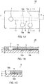
- FIG. 1 shows an example of the configuration of the first chip for analysis of a target substance of the present invention.
- FIG. 1(A) is a schematic perspective plan view
- FIG. 1(B) is a schematic cross sectional view of FIG. 1(A) viewed from the line I-I
- FIG. 1(C) is a schematic cross sectional view of FIG. 1(A) viewed from the line II-II.
- a chip for analysis of a target substance 10 includes a laminate in which a first flexible substrate 1, a second flexible substrate 2, and a third substrate 3 are laminated. In the laminate, the laminate direction of substrates is referred to as the up-and-down direction (hereinafter, the same applies).
- a flow channel-forming non-bonded area 11 is formed on the bonding surface of the first flexible substrate 1 and the second flexible substrate 2 in a band-like manner and an extraction chamber-forming non-bonded area 5 having a wider band width than the flow channel-forming non-bonded area 11 is formed at a part of the flow channel-forming non-bonded area 11.
- the first flexible substrate 1 includes a through-hole 7 that is in contact with the flow channel-forming non-bonded area 11.
- Shutter-forming non-bonded areas 12a and 12b are formed on the bonding surface of the second flexible substrate 2 and the third substrate 3 in a band-like manner at the near side and the far side of the through-hole 7 relative to the extraction chamber-forming non-bonded area 5 such that the shutter-forming non-bonded areas 12a and 12b and the flow channel-forming non-bonded area 11 intersect above and below via the second flexible substrate 2 being interposed therebetween.
- the first flexible substrate 1 and the second flexible substrate 2 include pressure supply ports 18a and 18b that come through the substrates so as to be in contact with the shutter-forming non-bonded areas 12a and 12b respectively.
- the third substrate 3 includes the pressure supply ports 18a and 18b that come through the substrate so as to be in contact with the shutter-forming non-bonded areas 12a and 12b respectively.
- a magnetic particle that binds to a target substance is placed above the extraction chamber-forming non-bonded area 5.
- the shutter-forming non-bonded area 12a and the pressure supply port 18a are optional components and are not indispensable, although the chip for analysis of a target substance of this Embodiment preferably includes these components.
- the flow direction of liquid in the flow channel to be formed is along the flow channel-forming non-bonded area 11 and the through-hole 7 side is the upstream side. Therefore, it can be said that the shutter-forming non-bonded area 12a is formed at the downstream side of the through-hole 7 and the upstream side of the extraction chamber-forming non-bonded area 5, i.e., between the through-hole 7 and the extraction chamber-forming non-bonded area 5, and the shutter-forming non-bonded area 12b is formed at the downstream side of the extraction chamber-forming non-bonded area 5.
- one through-hole 7 is provided at the left end of the flow channel-forming non-bonded area 11.
- the present invention is not limited thereto.
- An appropriate number of through-holes may be provided at any place as long as the through-hole is in contact with the flow channel-forming non-bonded area 11.
- one pressure supply port 18a is provided at the end of the shutter-forming non-bonded area 12a and one pressure supply port 18b is provided at the end of the shutter-forming non-bonded area 12b.
- the present invention is not limited thereto. An appropriate number of pressure supply ports may be provided at any place as long as the pressure supply port is in contact with the shutter-forming non-bonded area.
- shutter-forming non-bonded areas 12a and 12b and the flow channel-forming non-bonded area 11 intersect as long as the shutter-forming non-bonded areas 12a and 12b and the flow channel-forming non-bonded area 11 intersect above and below via the second flexible substrate 2 being interposed therebetween.
- the shutter-forming non-bonded areas 12a and 12b and the flow channel-forming non-bonded area 11 intersect at right angles in FIG. 1 , the present invention is not limited thereto.
- the undersurface of the first flexible substrate 1 and the top surface of the second flexible substrate 2 are bonded with each other at around the flow channel-forming non-bonded area 11, through-hole 7, and the extraction chamber-forming non-bonded area 5.
- the undersurface of the first flexible substrate 1 and the top surface of the second flexible substrate 2 are bonded with each other at an area excluding the flow channel-forming non-bonded area 11, the through-hole 7, and the extraction chamber-forming non-bonded area 5.
- the undersurface of the second flexible substrate 2 and the top surface of third substrate 3 are bonded with each other at an area excluding the shutter-forming non-bonded areas 12a and 12b and the pressure supply ports 18a and 18b.
- the chip for analysis of a target substance 10 can be produced, for example, as follows. First, the first flexible substrate 1, the second flexible substrate 2, and the third substrate 3 are provided. Surface modification treatment for the purpose of increasing the bonding strength between the substrates may be applied to the undersurface of the first flexible substrate 1, the top surface and the undersurface of the second flexible substrate 2, and the top surface of the third substrate 3. Examples of the surface modification treatment include oxygen plasma treatment and excimer UV light irradiation treatment.
- the oxygen plasma treatment can be performed, for example, using a reactive ion etching (RIE) apparatus and the like in the presence of oxygen.
- the excimer UV light irradiation treatment can be performed, for example, using a dielectric barrier discharge lamp under an air atmosphere of atmospheric pressure.
- Examples of the material of the first flexible substrate 1 include a silicone rubber such as polydimethylsiloxane (PDMS); a nitrile rubber; a hydrogenated nitrile rubber; a fluororubber; an ethylene-propylene rubber; a chloroprene rubber; an acrylic rubber; a butyl rubber; an urethane rubber; a chlorosulfonated polyethylene rubber; an epichlorohydrin rubber; a natural rubber; an isoprene rubber; a styrene-butadiene rubber; a butadiene rubber; a polysulfide rubber; a norbornene rubber; and a thermoplastic elastomer.
- PDMS polydimethylsiloxane
- a nitrile rubber such as polydimethylsiloxane (PDMS)
- a nitrile rubber such as polydimethylsiloxane (PDMS)
- a nitrile rubber such as polydi
- the thickness of the first flexible substrate 1 is, for example, in the range from 10 ⁇ m to 5 mm in consideration of the strength thereof and the formation of the flow channel and the extraction chamber that will be described below.
- the through-hole 7 and the pressure supply ports 18a and 18b can take any shape such as a cylinder shown in FIG. 1 and a prism, for example.
- the sizes of the through-hole 7 and the pressure supply ports 18a and 18b may be set appropriately, for example, according to the widths of the flow channel-forming non-bonded area and the shutter-forming non-bonded area that will be described below.
- the material of the second flexible substrate 2 examples include those described for the first flexible substrate 1. While the material of the second flexible substrate 2 can be the same as or different from the material of the first flexible substrate, the material of the second flexible substrate 2 is preferably the same as the material of the first flexible substrate 1. Specifically, for example, in the case where the first flexible substrate 1 is silicone rubber, the second flexible substrate 2 is preferably silicone rubber. If the first flexible substrate 1 and the second flexible substrate 2 are both silicone rubber, the first flexible substrate 1 and the second flexible substrate 2 can be bonded by a self adsorption ability without using an adhesive agent.
- the thickness of the second flexible substrate 2 is, for example, in the range from 10 ⁇ m to 500 ⁇ m in consideration of the strength thereof and the blocking of the flow channel that will be described below.
- the shapes and the sizes of the pressure supply ports 18a and 18b of the second flexible substrate 2 are, for example, the same as those of the pressure supply ports 18a and 18b of the first flexible substrate 1.
- the flow channel-forming non-bonded area 11 is formed on the top surface of the second flexible substrate 2 in a band-like manner and the extraction chamber-forming non-bonded area 5 having a wider band width than the flow channel-forming non-bonded area 11 is formed at a part of the flow channel-forming non-bonded area 11.
- the flow channel-forming non-bonded area 11 and the extraction chamber-forming non-bonded area 5 each can be formed as, for example, an electrode film, a dielectric protective film, a semiconductor film, a fluorescent film, a superconductive film, a dielectric film, a solar cell film, an antireflection film, a wear-resistant film, an optical interference film, a reflection film, an antistatic film, a conductive film, an antifouling film, a hard coating film, a barrier film, an electromagnetic wave shielding film, an infrared shielding film, an ultraviolet absorbing film, a lubricating film, a shape memory film, a magnetic recording film, a light-emitting element film, a biocompatible film, a corrosion-resistant film, a catalyst film, or a gas sensor film, for example, by a conventionally known chemical thin film formation technology.
- the aforementioned thin film can be formed by a plasma discharge treatment apparatus using an organic fluorine compound or a metal compound as reactive gas.
- organic fluorine compound examples include fluorocarbon compounds such as fluoromethane, fluoroethane, tetrafluoromethane, hexafluoromethane, 1,1,2,2-tetrafluoroethylene, 1,1,1,2,3,3-hexafluoropropane, hexafluoropropene, and 6-fluoropropylen; fluorohydrocarbon compounds such as 1,1-difluoroethylene, 1,1,1,2-tetrafluoroethane, and 1,1,2,2,3-pentafluoropropane; carbon fluorochloride compounds such as difluorodichloromethane and trifluorochloromethane; fluoroalcohols such as 1,1,1,3,3,3-hexafluoro-2-propanol, 1,3-difluoro-2-propanol, and perfluorobutanol; fluoro carboxylic ester such as vinyltrifluoroacetate and 1,1,1-trifluor
- the metal compound examples include a single metal compound, a mixed metal compound, and an organic metal compound of Al, As, Au, B, Bi, Ca, Cd, Cr, Co, Cu, Fe, Ga, Ge, Hg, In, Li, Mg, Mn, Mo, Na, Ni, Pb, Pt, Rh, Sb, Se, Si, Sn, Ti, V, W, Y, Zn, and Zr.
- the aforementioned thin film can be formed, for example, by a reactive ion etching system (RIE), a printing method, and the like in the presence of fluorocarbon (CHF3) via a mask.
- RIE reactive ion etching system
- CHF3 fluorocarbon
- the printing method for example, conventionally known printing methods such as roll printing, pattern printing, decalcomania, and electrostatic copying can be employed.
- a metal fine particle, a conductive ink, an insulating ink, a carbon fine particle, a silane agent, parylene, a paint, a pigment, a dye, a water-based dye ink, a water-based pigment ink, an oil dye ink, an oil pigment ink, a solvent ink, a solid ink, a gel ink, a polymer ink, and the like can be used suitably for the material for forming the thin film.
- the metal fine particle examples include a single metal fine particle of, a mixed metal fine particle of two or more of, an oxide fine particle (for example, ITO fine particle or the like) of the single metal or the mixed metal of, and an organic metal compound fine particle of Al, As, Au, B, Bi, Ca, Cd, Cr, Co, Cu, Fe, Ga, Ge, Hg, In, Li, Mg, Mn, Mo, Na, Ni, Pb, Pt, Rh, Sb, Se, Si, Sn, Ti, V, W, Y, Zn, and Zr.
- each of the flow channel-forming non-bonded area 11 and the extraction chamber-forming non-bonded area 5 is, for example, in the range from 10 nm to 10 ⁇ m and preferably in the range from 50 nm to 3 ⁇ m in consideration of uniform formation of the flow channel-forming non-bonded area 11 and the extraction chamber-forming non-bonded area 5 and the bonding ability between the first flexible substrate 1 and the second flexible substrate 2 at an area excluding the non-bonded area.
- the width of the flow channel-forming non-bonded area 11 is, for example, in the range from 10 ⁇ m to 3000 ⁇ m in consideration of the formation of the flow channel that will be described below, a supply amount of each of a reagent and a target substance such as DNA, and the like.
- the size of the extraction chamber-forming non-bonded area 5 is, for example, in the range from 3 mm2 to 300 mm2 and preferably in the range from 16 mm2 to 50 mm2 in consideration of the formation of the extraction chamber that will be described below, a supply amount of each of a reagent and a target substance such as DNA, and the like.
- the shape of the flow channel-forming non-bonded area 11 is not limited to a linear band shown in FIG. 1 , and, for example, various shaped bands such as a Y-shaped band and an L-shaped band can be employed.
- the shape of the extraction chamber-forming non-bonded area 5 is also not limited to a circle shown in FIG. 1 , and, for example, any shape such as a rectangle can be employed.
- Examples of the material of the third substrate 3 include acryl, a silicone rubber such as PDMS, glass, polyethylene terephthalate, polyethylene naphthalate, polyethylene, polypropylene, cellophane, cellulose diacetate, cellulose acetate butyrate, cellulose acetate propionate, cellulose acetate phthalate, cellulose triacetate, cellulose nitrate, polyvinylidene chloride, polyvinyl alcohol, ethylene vinyl alcohol, polycarbonate, a norbornene resin, polymethylpentene, polyether ketone, polyimide, polyethersulfone, polyether ketone imide, polyamide, a fluororesin, nylon, polymethyl methacrylate, polyarylate, a polylactic resin, polybutylene succinate, a nitrile rubber, a hydrogenated nitrile rubber, a fluororubber, an ethylene-propylene rubber, a chloroprene rubber, an acrylic rubber, a butyl rubber,
- surface treatment using a surface treatment agent is applied to the top surface of the third substrate 3 for the purpose of increasing the bonding ability between the top surface of the third substrate 3 and the undersurface of the second flexible substrate 2 at an area excluding the non-bonded area.
- the surface treatment agent include alkylsilane such as dimethylsilane, tetramethylsilane, and tetraethylsilane; organic silicon compounds of silicon alkoxysilane such as tetramethoxysilane, tetraethoxysilane, tetrapropoxysilane, dimethyldiethoxysilane, methyltrimethoxysilane, and ethyltriethoxysilane; silicon-hydrogen compounds such as monosilane and disilane; halogenated silicon compounds such as dichlorosilane, trichlorosilane, and tetrachlorosilane; silazane such as hexamethyldisilazane; and silicon
- Shutter-forming non-bonded areas 12a and 12b are formed on the top surface of the third substrate 3 in a band-like manner.
- the shutter-forming non-bonded areas 12a and 12b may be formed, for example, using the same material as those used for the flow channel-forming non-bonded area 11 and the extraction chamber-forming non-bonded area 5 such that the shutter-forming non-bonded areas 12a and 12b have the same thickness as the flow channel-forming non-bonded area 11 and the extraction chamber-forming non-bonded area 5.
- the width of each of the shutter-forming non-bonded areas 12a and 12b is, for example, in the range from 10 ⁇ m to 5000 ⁇ m in consideration of the blocking of the flow channel that will be described below and economic efficiency.
- the first flexible substrate 1, the second flexible substrate 2, and the third substrate 3 are laminated.
- a magnetic particle that binds to a target substance such as DNA is placed above the extraction chamber-forming non-bonded area 5.
- "Bonding" may be, for example, direct or indirect bonding of the target substance to the magnetic particle.
- an example of the direct bonding includes adhesion of the target substance to the magnetic particle itself.
- examples of the indirect bonding include adsorption or adhesion of the target substance to a predetermined substance to which a magnetic particle coating is applied and bonding of the target substance to the magnetic particle by reaction using a reactive substance.
- the magnetic particle is , for example, a sphere and the particle size is, for example, in the range from 0.3 ⁇ m to 5 ⁇ m.
- the magnetic particle for example, a substance having a porous surface or a substance in which at least one of silica gel and cellulose is mixed is suitable. In this manner, the chip for analysis of a target substance 10 shown in FIG. 1 can be obtained.
- the first target substance analysis method of the present invention can be performed using the first chip for analysis of a target substance of the present invention.
- the first target substance analysis method is characterized, for example, by using the first chip for analysis of a target substance of the present invention and including the following steps (a1) to (d1):
- the steps may be performed in the order from step (a1) to step (d1).
- the shutter portion formation step (a1) and the flow channel and extraction chamber formation step (b1) may be performed simultaneously or either of the steps (a1) and (b1) may be performed in advance, for example.
- the analysis sample injection step (c1) may be performed simultaneously with the flow channel and extraction chamber formation step (b1), for example.
- FIG. 2 As the first target substance analysis method of the present invention, an example of the usage of the chip for analysis of a target substance 10 shown in FIG. 1 will be described with reference to FIG. 2 .
- the aspect shown in FIG. 2 is an example and the present invention is not limited to this aspect.
- an adapter 14 is provided at the opening portion of the through-hole 7 serving as an introduction portion of liquid or gas, and an injection tube 15 is connected to the adapter 14.
- the shape of the adapter 14 is not limited to that shown in FIG. 2(A) .
- the adapter 14 may not be in the form of partially inserted in the through-hole 7 but may be in the form of directly fixed to the top surface of the first flexible substrate 1.
- the injection tube 15 may be directly connected to the through-hole 7 without using the adapter 14.
- the material for the adapter 14 although a silicone rubber such as PDMS is preferable, any other material can be used.
- an appropriate adhesive agent may be used for fixing the adapter 14 to the top surface of the first flexible substrate 1.
- An example of the injection tube 15 includes a Teflon (registered trademark) tube. One end of the injection tube 15 is fixed to the adapter 14 using an appropriate adhesive agent. The other end of the injection tube 15 is connected to an appropriate undiluted solution supply means, an appropriate pressure application means (for example, a micro-pump, a syringe, or the like), and the like although it is not shown.
- the adapter 14 to which the injection tube 15 is connected is provided also at each of the pressure supply ports 18a and 18b although it is not shown. Then, gas is injected at high pressure from the injection tube 15 via the pressure supply port 18b. Thereby, as shown in FIG. 2(B) , a site above the shutter-forming non-bonded area 12b is raised to form the shutter-forming void 17b. Specifically, only a part of the first flexible substrate 1 and a part of the second flexible substrate 2 positioned above the shutter-forming non-bonded area 12b are raised from the top surface of the third substrate 3 to form the shutter-forming void 17b.
- the shutter-forming void 17b formed by raising is also referred to as a shutter portion (hereinafter, the same applies).
- the gas is, for example, air or the like, and the level of high pressure is, for example, in the range from 10 kPa to 300 kPa (hereinafter, the same applies).
- a liquid analysis sample to be analyzed is injected into the chip for analysis of a target substance 10.
- the type of the analysis sample there is no particular limitation on the type of the analysis sample, and, for example, the type of the analysis sample can be selected appropriately according to the type of the target substance.
- the target substance include cells and intracellular components, and specific examples thereof include nucleic acids such as DNA and RNA.
- the analysis sample may be, for example, a sample in which a target substance is eluted from a cell, i.e., an elution sample of a cell (also referred to as a target substance-eluted sample), or a sample in which a target substance is not eluted from a cell, i.e., a sample that contains a cell.
- the target substance such as the nucleic acid or the like may be eluted from a cell in the analysis sample in the chip for analysis of a target substance 10.
- gas is injected at high pressure from the injection tube 15 after injecting the analysis sample into the through-hole 7 or the analysis sample is injected into the through-hole 7 with application of positive pressure.
- a site above the flow channel-forming non-bonded area 11 and a site above the extraction chamber-forming non-bonded area 5 are raised and the flow channel 8 and the extraction chamber 6 are formed.
- only parts of the first flexible substrate 1 positioned above the flow channel-forming non-bonded area 11 and the extraction chamber-forming non-bonded area 5 are raised from the top surface of the second flexible substrate 2 to form the flow channel 8 and extraction chamber 6.
- a site above the flow channel-forming non-bonded area 11 positioned further ahead of the shutter-forming void 17b i.e., a site above the flow channel-forming non-bonded area 11 positioned at the downstream side of the shutter-forming void 17b is blocked by the shutter-forming void 17b, and therefore the flow channel is not formed.
- the target substance contained in the analysis sample that has been injected binds to the magnetic particle 16.
- an elution reagent that causes a target substance such as a nucleic acid to be eluted from the cell may be injected into the chip for analysis of a target substance 10 before, at the same time as, or after the injection of the analysis sample.
- the method of injection is, for example, the same as that described for the analysis sample.
- the target substance eluted from the cell by the elution reagent binds to the magnetic particle 16 in the extraction chamber 6. It is also possible to preliminarily place the elution reagent, for example, at the extraction chamber-forming non-bonded area 5 or at the flow channel-forming non-bonded area 11 between the through-hole 7 and the extraction chamber-forming non-bonded area 5.
- a washing reagent is injected into the chip for analysis of a target substance 10.
- the washing reagent is injected from the injection tube 15 via the through-hole 7 in the same manner as the analysis sample.
- a magnetic field is generated at the undersurface of the third substrate 3. Specifically, a magnetic field is generated at the undersurface of the third substrate 3 directly below the end of the extraction chamber 6 at the opposite side of the through-hole 7. Thereby, in the extraction chamber 6, a target substance such as DNA that is bound to the magnetic particle 16 is captured. In this manner, by generating a magnetic field at the undersurface of the third substrate 3, the leak of the magnetic particle 16 to the flow channel 8 further ahead of the extraction chamber 6 can be prevented even in the case where the flow channel 8 is formed at the downstream side of the extraction chamber 6.
- the magnetic field may be generated, for example, at the top surface side of the first flexible substrate 1. Specifically, the magnetic field may be generated at the top surface side of the first flexible substrate 1 directly above the end of the extraction chamber 6 at the opposite side of the through-hole 7.
- a method of generating a magnetic field there is no particular limitation on the method of generating a magnetic field, and an example thereof includes a method of making the chip for analysis of a target substance 10 into contact with a magnet 13 such as an electromagnet or a permanent magnet such as an alnico magnet, a ferrite magnet, a neodymium magnet, or a samarium-cobalt magnet.
- a magnet 13 such as an electromagnet or a permanent magnet such as an alnico magnet, a ferrite magnet, a neodymium magnet, or a samarium-cobalt magnet.
- the pressure of the gas injecting from the through-hole 7 and the pressure supply port 18b is set about atmospheric pressure.
- the shutter-forming void 17b and the voids of the flow channel 8 and the extraction chamber 6 are vanished.
- gas is injected at high pressure from the injection tube 15 via the through-hole 7.
- substances excluding the target substance that is bound to the magnetic particle 16, e.g., the washing reagent and the like can be discharged from the flow channel 8.
- the chip for analysis of a target substance of this Embodiment allows extraction of a target substance such as DNA from the analysis sample efficiently by the magnetic particle 16.
- the extraction chamber can be also referred to as, for example, a separation chamber of the target substance.
- FIG. 3 shows an example of the configuration of a second chip for analysis of a target substance not covered by the present invention.
- identical parts to those shown in FIGs.1 and 2 are indicated with identical numerals and symbols.
- the chip for analysis of a target substance 10 shown in FIG. 3 has the configuration identical to that of the chip for analysis of a target substance 10 shown in FIGs. 1 and 2 except that the extraction chamber-forming non-bonded area 5 has the function of a mixing chamber-forming non-bonded area 9 and does not contain the magnetic particle 16.
- the chip for analysis of a target substance of this Embodiment allows mixing of the reagent and the analysis sample or the target substance in the analysis sample in the mixing chamber 19 in the manner described below.
- the reagent can be selected appropriately according to, for example, the type of the analysis sample, the type of the target substance, and the analysis method.
- Specific examples of the reagent include the aforementioned elution reagent that causes a target substance to be eluted from the cell, a reaction reagent that reacts with the target substance, and the washing reagent.
- the second target substance analysis method can be performed using the second chip for analysis of a target substance.
- the second target substance analysis method is characterized, for example, by using the second chip for analysis of a target substance and including the following steps (a2) to (f2):
- the steps may be performed in the order from step (a2) to step (f2).
- the shutter portion formation step (a2) and the flow channel and mixing chamber formation step (b2) may be performed simultaneously or either of the steps (a2) and (b2) may be performed in advance, for example.
- the analysis sample injection step (c2) and the reagent injection step (d2) may be performed simultaneously or either of the steps (c2) and (d2) may be performed in advance, for example.
- the analysis sample injection step (c2) and the reagent injection step (d2) may be performed simultaneously with the flow channel and mixing chamber formation step (b2), for example.
- the steps to the analysis sample injection step are performed in the same manner as in Embodiment 1.
- the extraction chamber 6 is formed in Embodiment 1 whereas the mixing chamber 19 is formed in this Embodiment.
- the aforementioned various reagents may be injected into the chip for analysis of a target substance 10, for example, before, at the same time as, or after the injection of the analysis sample.
- the method of injection is, for example, the same as that described for the analysis sample.
- the analysis sample is the sample that contains a cell as described above
- the elution reagent the reaction reagent that reacts with the eluted target substance, the washing reagent that washes the target substance, and the like may be injected as the reagent.
- the reaction reagent, the washing reagent, and the like may be injected as the reagent.
- elution reagent and the reaction reagent for example, at the mixing chamber-forming non-bonded area 9 or at the flow channel-forming non-bonded area 11 between the through-hole 7 and the mixing chamber-forming non-bonded area 9.
- gas is injected at high pressure from the injection tube 15 via the pressure supply port 18a.
- a site above the shutter-forming non-bonded area 12a is raised to form the shutter-forming void 17a.
- the gas is, for example, air or the like, and the level of high pressure is, for example, in the range from 10 kPa to 300 kPa (hereinafter, the same applies).
- the pressure of the gas injecting from the through-hole 7 is set about atmospheric pressure. Thereby, as shown in FIG. 3(C) , the void of the flow channel 8 at the upstream side of the shutter-forming void 17a is vanished.
- the mixing chamber 19 is deformed by applying pressure to the top surface of the first flexible substrate 1 above the mixing chamber 19. Thereby, the target substance and the reagent are mixed in the mixing chamber 19.
- the pressure of the gas injecting from the pressure supply ports 18a and 18b is set about atmospheric pressure.
- the shutter-forming voids 17a and 17b and the void of the mixing chamber 19 are vanished.
- gas is injected at high pressure from the injection tube 15 via the through-hole 7.
- the target substance mixed with the reagent can be forwarded to the next step.
- the same magnetic particle as described in Embodiment 1 may be placed at the mixing chamber-forming non-bonded area 9.
- the mixing chamber 19 also has the function of an extraction chamber.
- the third chip for analysis of a target substance in the third chip for analysis of a target substance, as described above, two shutter-forming non-bonded areas are formed on the bonding surface of the second flexible substrate and the third substrate at the near side of the through-hole relative to the first mixing chamber-forming non-bonded area and at the far side of the through-hole relative to the second mixing chamber-forming non-bonded area.
- the third shutter-forming non-bonded area may be further formed on the bonding surface of the second flexible substrate and the third substrate in a band-like manner such that the third shutter-forming non-bonded area and the flow channel-forming non-bonded area intersect above and below via the second flexible substrate being interposed therebetween.
- This shutter-forming non-bonded area may be formed at the far side of the through-hole relative to the first mixing chamber-forming non-bonded area, for example.
- the flow channel at the upstream side and the downstream side of the first mixing chamber can be blocked respectively by the shutter portions.
- FIG. 4 shows an example of the configuration of the third chip for analysis of a target substance.
- the chip for analysis of a target substance 10 shown in FIG. 4 has the configuration identical to that of the chip for analysis of a target substance shown in FIG. 3 except that the chip for analysis of a target substance 10 shown in FIG. 4 includes two mixing chamber-forming non-bonded areas (9a and 9b), four shutter-forming non-bonded areas (12a to 12d), and four pressure supply ports. Although it is not shown, four pressure supply ports are referred to as pressure supply ports 18a to 18d for convenience sake.
- the shutter-forming non-bonded areas 12c and 12d are respectively in contact with the pressure supply ports 18c and 18d that come through the first flexible substrate 1 and the second flexible substrate 2 as in the case of the shutter-forming non-bonded areas 12a and 12b shown in FIG. 1(A) .
- the pressure supply ports 18c and 18d may be formed on the third substrate 3 in such a manner that they come through the third substrate 3 so as to be in contact with the shutter-forming non-bonded areas 12c and 12d.
- the shutter-forming non-bonded areas 12b and 12c and the pressure supply ports 18b and 18c are optional components and are not indispensable, although the chip for analysis of a target substance of this Embodiment preferably includes these components.
- the shutter-forming non-bonded areas 12b and 12c and the pressure supply ports 18b and 18c may be respectively formed as one component, and the number of the non-bonded areas and the pressure supply ports may be respectively three.
- the third target substance analysis method can be performed using the third chip for analysis of a target substance.
- the third target substance analysis method is characterized, for example, by using the third chip for analysis of a target substance and including the following steps (a3) to (f3):
- the steps may be performed in the order from step (a3) to step (f3).
- the step (d3) may be performed, for example, before, at the same time as, or after the step (a3) and is preferably performed before the steps (b3) and (c3).
- the step (e3) is preferably performed, for example, after the steps (b3) and (c3).
- the formation of the first mixing chamber and the second mixing chamber in the step (a3) may be performed, for example, as a separated step.
- the step (a3) may be the steps (a3-1) and (a3-2) described below:
- the first mixing chamber formation step (a3-1) is preferably performed before or at the same time as the analysis sample injection step (b3) and the reagent injection step (c3).
- the second mixing chamber formation step (a3-2) may be performed, for example, before, after, or during the shutter portion formation steps (d3) and (e3).
- a shutter portion may be formed by raising a site above the third shutter-forming non-bonded area.
- the chip for analysis of a target substance 10 shown in FIG. 4 is used, for example, as follows. First, as shown in FIG. 4(A) , in the same manner as in Embodiment 1, the adapter 14 to which the injection tube 15 is connected is provided at each of the through-hole 7 and the pressure supply ports 18a to 18d.
- gas is injected at high pressure from the injection tube 15 via the pressure supply port 18b.
- a site above the shutter-forming non-bonded area 12b is raised to form the shutter-forming void 17b.
- the gas is, for example, air or the like, and the level of high pressure is, for example, in the range from 10 kPa to 300 kPa (hereinafter, the same applies).
- gas is injected at high pressure from the injection tube 15 after injecting the analysis sample into the through-hole 7 or the analysis sample is injected into the through-hole 7 with application of positive pressure.
- a site above the flow channel-forming non-bonded area 11 and a site above the first mixing chamber-forming non-bonded area 9a are raised and the flow channel 8 and the first mixing chamber 19a are formed.
- only parts of the first flexible substrate 1 positioned above the flow channel-forming non-bonded area 11 and the first mixing chamber-forming non-bonded area 9a are raised from the top surface of the second flexible substrate 2 to form the flow channel 8 and the first mixing chamber 19a.
- the reagent is injected into the chip for analysis of a target substance 10.
- the analysis sample is the sample that contains a cell as described above and the elution reagent is used as the reagent, a target substance such as DNA is eluted from the cell in the first mixing chamber 19a.
- gas is injected at high pressure from the injection tube 15 via the pressure supply port 18a.
- a site above the shutter-forming non-bonded area 12a is raised to form the shutter-forming void 17a.
- the gas is, for example, air or the like, and the level of high pressure is, for example, in the range from 10 kPa to 300 kPa (hereinafter, the same applies).
- the pressure of the gas injecting from the through-hole 7 is set about atmospheric pressure. Thereby, as shown in FIG. 4(C) , the void of the flow channel 8 at the upstream side of the shutter-forming void 17a is vanished.
- the pressure of the gas injecting from the pressure supply port 18b is set about atmospheric pressure.
- the void of the shutter-forming void 17b is vanished.
- gas is injected at high pressure from the injection tube 15 via the pressure supply port 18d.
- a site above the shutter-forming non-bonded area 12d is raised to form the shutter-forming void 17d.
- only a part of the first flexible substrate 1 and a part of the second flexible substrate 2 positioned above the shutter-forming non-bonded area 12d are raised from the top surface of the third substrate 3 to form the shutter-forming void 17d.
- pressure is alternately applied to the top surface of the first flexible substrate 1 positioned above the first mixing chamber 19a and the top surface of the first flexible substrate 1 positioned above the second mixing chamber 19b to alternately deform the first mixing chamber 19a and the second mixing chamber 19b.
- the target substance and the reagent are mixed by moving between the first mixing chamber 19a and the second mixing chamber 19b.
- the method of mixing the target substance and the reagent by moving them between the first mixing chamber 19a and the second mixing chamber 19b is not limited to the method of alternately applying pressure to a site above the first mixing chamber 19a and a site above the second mixing chamber 19b to alternately deform the first mixing chamber 19a and the second mixing chamber 19b, and any method can be employed.
- the target substance and the reagent may be mixed by applying air pressure between the first mixing chamber 19a and the second mixing chamber 19b to move the target substance and the reagent between the first mixing chamber 19a and the second mixing chamber 19b.
- the pressure of the gas injecting from the through-hole 7 and the pressure supply ports 18a and 18d is set about atmospheric pressure.
- the shutter-forming voids 17a and 17d and the voids of the flow channel 8, the first mixing chamber 19a, and the second mixing chamber 19b are vanished.
- gas is injected at high pressure from the injection tube 15 via the through-hole 7.
- the target substance mixed with the reagent can be forwarded to the next step.
- the same magnetic particle as described in Embodiment 1 may be placed at at least one of the first mixing chamber-forming non-contact (non-bonded) area 9a and the second mixing chamber-forming non-bonded area 9b.
- at least one of the first mixing chamber 19a and the second mixing chamber 19b has the function of an extraction chamber.
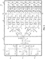
- FIG. 5 shows another example of the configuration of the chip for analysis of a target substance.
- a chip for analysis of a target substance 20 shown in FIG. 5 includes, in addition to the configuration of the chip for analysis of a target substance 10 shown in FIGs. 1 and 2 , a washing reagent supply portion 30, a PCR reaction reagent supply portion 40, a washing reagent recovery portion 70, a PCR amplification portion 50, a shutter-forming non-bonded area 12m, a pressure supply port 18m, and an electrophoresis analysis portion 60 as main components.
- the washing reagent supply portion 30, the PCR reaction reagent supply portion 40, the washing reagent recovery portion 70, the PCR amplification portion 50, and the electrophoresis analysis portion 60 each include a laminate in which the first flexible substrate 1, the second flexible substrate 2, and the third substrate 3 are laminated.
- the material of each of the first flexible substrate 1, the second flexible substrate 2, and the third substrate 3 is the same as that of the chip for analysis of a target substance 10 shown in FIGs. 1 and 2 .
- the shutter-forming non-bonded area 12m and the pressure supply port 18m can be formed in the same manner as the corresponding components of the chip for analysis of a target substance 10 shown in FIGs. 1 and 2 .
- the washing reagent supply portion 30 includes a through-hole 37, a flow channel-forming non-bonded area 31, a shutter-forming non-bonded area 12e, and a pressure supply port 18e as main components. These components can be formed in the same manner as the corresponding components of the chip for analysis of a target substance 10 shown in FIGs. 1 and 2 .
- the flow channel-forming non-bonded area 31 is in contact with the extraction chamber-forming non-bonded area 5 of the chip for analysis of a target substance 10 shown in FIGs. 1 and 2 .
- the washing reagent supply portion 30 is an optional component and is not indispensable, although the chip for analysis of a target substance 20 preferably includes the washing reagent supply portion 30. In the case where the chip for analysis of a target substance 20 does not include the washing reagent supply portion 30, a washing reagent may be supplied from the through-hole 7 of the chip for analysis of a target substance 10 shown in FIGs. 1 and 2 .
- the PCR reaction reagent supply portion 40 includes a through-hole 47, a flow channel-forming non-bonded area 41, a shutter-forming non-bonded area 12f, and a pressure supply port 18f as main components. These components can be formed in the same manner as the corresponding components of the chip for analysis of a target substance 10 shown in FIGs. 1 and 2 .
- the flow channel-forming non-bonded area 41 is in contact with the extraction chamber-forming non-bonded area 5 of the chip for analysis of a target substance 10 shown in FIGs. 1 and 2 .
- the PCR reagent supply portion 40 is an optional component and is not indispensable, although the chip for analysis of a target substance 20 preferably includes the PCR reagent supply portion 40.
- a PCR reagent may be supplied from the through-hole 7 of the chip for analysis of a target substance 10 shown in FIGs. 1 and 2 .
- the washing reagent recovery portion 70 includes a flow channel-forming non-bonded area 71, shutter-forming non-bonded areas 12n and 12o, pressure supply ports 18n and 18o, and a waste tank 78 as main components.
- the components except for the waste tank 78 can be formed in the same manner as the corresponding components of the chip for analysis of a target substance 10 shown in FIGs. 1 and 2 .
- the waste tank 78 can be formed in the same manner as the extraction chamber-forming non-bonded area 5 of the chip for analysis of a target substance 10 shown in FIGs. 1 and 2 .
- the flow channel-forming non-bonded area 11 led out from the chip for analysis of a target substance 10 shown in FIGs. 1 and 2 is split into eight flow channel-forming non-bonded areas 51a to 51h via the shutter-forming non-bonded areas 12g to 12l and pressure supply ports 18g to 18l.
- the number of the split of the flow channel-forming non-bonded area is not limited to eight and can be increased or decreased appropriately according to a desired analysis accuracy of the target substance.
- the shutter-forming non-bonded areas 12g to 121, the pressure supply ports 18g to 18l, and the flow channel-forming non-bonded areas 51a to 51h can be formed in the same manner as the corresponding components of the chip for analysis of a target substance 10 shown in FIGs.
- Eight flow channel-forming non-bonded areas 51a to 51 h are respectively in contact with eight reaction tanks 52a to 52h.
- shutter-forming non-bonded areas 12p to 12z and 12 ⁇ to 12 ⁇ and pressure supply ports 18p to 18z and 18 ⁇ to 18 ⁇ are respectively formed.
- There is no particular limitation on the method of forming the reaction tanks 52a to 52h and, for example, a formation method in a conventionally known PCR chip can be employed.
- the shutter-forming non-bonded areas 12p to 12z and 12 ⁇ to 12 ⁇ and the pressure supply ports 18p to 18z and 18 ⁇ to 18 ⁇ can be formed in the same manner as the corresponding components of the chip for analysis of a target substance 10 shown in FIGs. 1 and 2 .
- heating means such as heaters are placed.
- the electrophoresis analysis portion 60 includes reagent tanks 67a to 67h, through-holes 68a to 68h, flow channel-forming non-bonded areas 61a to 61h and 62a to 62h, waste tanks 65a to 65h and 66a to 66h, and electrodes 67i to 67p, 68i to 68p, 65i to 65p, and 66i to 66p.
- the reagent tanks 67a to 67h are formed so as to be in contact with the flow channel-forming non-bonded areas 51a to 51h of the PCR amplification portion 50 via the shutter-forming non-bonded area 12m and the pressure supply port 18m.
- the flow channel-forming non-bonded areas 61a to 61h are formed so as to be in contact with the reagent tanks 67a to 67h at one end and be in contact with the waste tanks 65a to 65h at the other end.
- the flow channel-forming non-bonded areas 62a to 62h are formed so as to intersect with the flow channel-forming non-bonded areas 61a to 61h, be in contact with the through-holes 68a to 68h at one end, and be in contact with the waste tanks 66a to 66h at the other end.
- the electrodes 67i to 67p, 68i to 68p, 65i to 65p, and 66i to 66p are respectively placed. It is possible to apply voltages to the electrodes 67i to 67p, 68i to 68p, 65i to 65p, and 66i to 66p from above the first flexible substrate 1 or below third substrate 3.
- the through-holes 67a to 67h and the flow channel-forming non-bonded areas 61a to 61h and 62a to 62h can be formed in the same manner as the corresponding components of the chip for analysis of a target substance 10 shown in FIGs. 1 and 2 .
- the groove has, for example, a width of about 100 ⁇ m and a depth of about 30 ⁇ m.
- the reagent tanks 67a to 67h and the waste tanks 65a to 65h and 66a to 66h can be formed in the same manner as the extraction chamber-forming non-bonded area 5 of the chip for analysis of a target substance 10 shown in FIGs. 1 and 2 .
- As the electrodes 67i to 67p, 68i to 68p, 65i to 65p, and 66i to 66p conventionally known ones can be used.
- optical analysis means such as absorbance measuring apparatuses are placed.
- the chip for analysis of a target substance 20 of this Embodiment may include the configuration of the chip for analysis of a target substance 10 including the mixing chamber-forming non-bonded area shown in FIG. 3 or FIG. 4 instead of the chip for analysis of a target substance 10 including the extraction chamber-forming non-bonded area 5 shown in FIGs. 1 and 2 . Furthermore, the chip for analysis of a target substance 20 of this Embodiment may further include a through-hole and a flow channel-forming non-bonded area for dry air supply that are formed so as to be in contact with the extraction chamber-forming non-bonded area or the mixing chamber-forming non-bonded area.
- the size of the chip for analysis of a target substance 20 of this Embodiment is as follows. That is, for example, the length is in the range from 50 mm to 300 mm and the width is in the range from 20 mm to 100 mm. Since the chip for analysis of a target substance of the present invention is compact as described above, it allows a small installation space.
- the thickness of the chip for analysis of a target substance 20 of this Embodiment excluding the mechanism for generating a magnetic field in the configuration of the chip for analysis of a target substance 10 shown in FIGs. 1 and 2 , the heating means in the PCR amplification portion 50, and the optical analysis means in the electrophoresis analysis portion 60 is, for example, in the range from 0.5 mm to 5 mm. Therefore, the chip for analysis of a target substance 20 of this Embodiment can be carried around without fixing at a predetermined space.
- the chip for analysis of a target substance 20 shown in FIG. 5 is used, for example, as follows. First, in the same manner as in Embodiment 1, the target substance such as DNA is extracted from the analysis sample using the configuration of the chip for analysis of a target substance 10 shown in FIGs. 1 and 2 and the washing reagent supply portion 30. The time required for extracting the target substance is, for example, about 5 minutes.
- the target substance that is bound to a magnetic particle is transferred to the washing reagent recovery portion 70 by supplying the PCR reaction reagent from the PCR reaction reagent supply portion 40.
- a solution obtained by removing the washing reagent from a mixture of the target substance, the washing reagent, the PCR reaction reagent, and the like is transferred to the PCR amplification portion 50.
- PCR amplification is performed by a conventionally known method such as a method of applying a temperature cycle to the target substance and the PCR reaction reagent stored in the reaction tanks 52a to 52h.
- the time required for this PCR amplification is, for example, in the range from 10 minutes to 60 minutes and preferably about 15 minutes.
- electrophoresis analysis is performed by introducing a small amount of amplification products of the target substance from the intersection site of the flow channel-forming non-bonded areas 61a to 61h and 62a to 62h to the flow channels formed above the flow channel-forming non-bonded areas 62a to 62h.
- the time required for this electrophoresis analysis is, for example, about 5 minutes.
- Such an electrophoresis analysis method is conventionally known.
- the chip for analysis of a target substance 20 of this Embodiment allows extraction, amplification, and analysis of a target substance such as DNA with less effort and less time such as from about 20 minutes to about 70 minutes.
- the chip for analysis of a target substance 20 shown in FIG. 5 includes the PCR amplification portion 50 and the electrophoresis analysis portion 60.
- the chip for analysis of a target substance of this Embodiment may be the one that performs electrophoresis analysis without performing PCR amplification.
- the chip for analysis of a target substance of this Embodiment may be the one that analyzes the target substance by a method other than electrophoresis analysis such as chemiluminescence, fluorescence, or enzyme coloration.
- analysis of the target substance such as DNA may be performed by a conventional known method such as an intercalation method or a method using a fluorescent-labeled probe.
- the chip for analysis of a target substance of the present invention is compact and allows analysis of a target substance such as DNA with less time and effort.
- the chip for analysis of a target substance of the present invention can be applied to a wide range of uses including, for example, DNA analysis in a criminal investigation.
Landscapes
- Chemical & Material Sciences (AREA)
- Health & Medical Sciences (AREA)
- Life Sciences & Earth Sciences (AREA)
- Chemical Kinetics & Catalysis (AREA)
- Analytical Chemistry (AREA)
- General Health & Medical Sciences (AREA)
- Molecular Biology (AREA)
- Physics & Mathematics (AREA)
- Dispersion Chemistry (AREA)
- Immunology (AREA)
- Biochemistry (AREA)
- Hematology (AREA)
- Clinical Laboratory Science (AREA)
- General Physics & Mathematics (AREA)
- Electrochemistry (AREA)
- Pathology (AREA)
- Organic Chemistry (AREA)
- Wood Science & Technology (AREA)
- Proteomics, Peptides & Aminoacids (AREA)
- Engineering & Computer Science (AREA)
- Zoology (AREA)
- Fluid Mechanics (AREA)
- Microbiology (AREA)
- Biotechnology (AREA)
- Bioinformatics & Cheminformatics (AREA)
- General Engineering & Computer Science (AREA)
- Genetics & Genomics (AREA)
- Biophysics (AREA)
- Automatic Analysis And Handling Materials Therefor (AREA)
- Apparatus Associated With Microorganisms And Enzymes (AREA)
- Measuring Or Testing Involving Enzymes Or Micro-Organisms (AREA)
Claims (5)
- Chip (10, 20) zur Analyse eines Zielstoffs, umfassend:eine Magnetfelderzeugungseinheit (13), die zum Erzeugen eines Magnetfelds konfiguriert ist;eine oder mehr Positionen auf dem Chip, die zum Einfangen eines magnetischen Teilchens (16) zur Bindung an einen Zielstoff konfiguriert sind; undein Laminat, umfassend:einen ersten flexiblen Träger (1);einen zweiten flexiblen Träger (2);einen dritten Träger (3);einen einen Strömungskanal bildenden nicht gebondeten Bereich (11, 31, 41, 51, 61, 62, 71), der auf einer Bondfläche des ersten flexiblen Substrats (1) und des zweiten flexiblen Substrats (2) bandartig ausgebildet ist; undeinen eine Extraktionskammer bildenden nicht gebondeten Bereich (5) mit einer breiteren Bandbreite als der den Strömungskanal bildende nicht gebondete Bereich, der an einem Teil des den Strömungskanal bildenden nicht gebondeten Bereichs (11, 31, 41, 51, 61, 62, 71) ausgebildet ist;wobei der erste flexible Träger ein Durchgangsloch (7, 37, 47, 68) aufweist, das mit dem den Strömungskanal bildenden nicht gebondeten Bereich (11, 31, 41, 51, 61, 62, 71) in Kontakt ist,einen einen Verschluss bildenden nicht gebondeten Bereich (12), der an einer Bondfläche des zweiten flexiblen Trägers (2) und des dritten Trägers (3) an einer fernen Seite des Durchgangslochs (7, 37, 47, 68) relativ zu dem die Extraktionskammer bildenden nicht gebondeten Bereich (5) bandartig ausgebildet ist, so dass der den Verschluss bildende nicht gebondete Bereich (12) und der den Strömungskanal bildende nicht gebondete Bereich (11, 31, 41, 51, 61, 62, 71) über den dazwischen gelegten zweiten flexiblen Träger (2) Folgendes schneiden;eines der Folgenden oder beide:a) den ersten flexiblen Träger (1) und den zweiten flexiblen Träger (2) undb) den dritten Träger,umfassend:einen Druckanlegeanschluss (18) durch die Träger (1, 2) oder den Träger (3), um mit dem den Verschluss bildenden nicht gebondeten Bereich (12) in Kontakt zu sein,einen Strömungskanal (8) und eine Extraktionskammer (6), die durch Anlegen von Druck aus dem Durchgangsloch, um eine Stelle über dem den Strömungskanal bildenden nicht gebondeten Bereich und eine Stelle über dem die Extraktionskammer bildenden nicht gebondeten Bereich (5) anzuheben, bildbar sind,wobei der Strömungskanal (8) durch Anlegen von Druck aus dem Druckanlegeanschluss (18) blockierbar ist, um eine Stelle über dem den Verschluss bildenden nicht gebondeten Bereich (12) anzuheben, undwobei eine der ein oder mehr Positionen der die Extraktionskammer bildende nicht gebondete Bereich ist;die Magnetfelderzeugungseinheit (13) an einer Außenseite von dem ersten flexiblen Träger und/oder dem dritten Träger angeordnet ist und an ein Ende der Extraktionskammer am entgegengesetzten Ende des Durchgangslochs angrenzend angeordnet ist und zum Einfangen des Zielstoffs konfiguriert ist, der an das Magnetteilchen gebunden ist.
- Chip nach Anspruch 1, der ferner einen Verstärkungsteil umfasst.
- Chip nach Anspruch 2, wobei der Verstärkungsteil einen PCR-Verstärkungsteil (50) umfasst.
- Chip nach einem der Ansprüche 1 bis 3, der ferner umfasst: einen Analyseteil.
- Chip nach Anspruch 4, wobei der Analyseteil einen Elektrophorese-Analyseteil (60) umfasst.
Applications Claiming Priority (2)
| Application Number | Priority Date | Filing Date | Title |
|---|---|---|---|
| JP2012063645 | 2012-03-21 | ||
| PCT/JP2013/051332 WO2013140846A1 (ja) | 2012-03-21 | 2013-01-23 | 対象物質分析チップ |
Publications (4)
| Publication Number | Publication Date |
|---|---|
| EP2829882A1 EP2829882A1 (de) | 2015-01-28 |
| EP2829882A4 EP2829882A4 (de) | 2015-12-02 |
| EP2829882B1 true EP2829882B1 (de) | 2020-02-19 |
| EP2829882B8 EP2829882B8 (de) | 2020-04-01 |
Family
ID=49222314
Family Applications (1)
| Application Number | Title | Priority Date | Filing Date |
|---|---|---|---|
| EP13764529.7A Active EP2829882B8 (de) | 2012-03-21 | 2013-01-23 | Chip zur analyse einer zielsubstanz |
Country Status (5)
| Country | Link |
|---|---|
| US (2) | US20150050721A1 (de) |
| EP (1) | EP2829882B8 (de) |
| JP (2) | JPWO2013140846A1 (de) |
| DK (1) | DK2829882T3 (de) |
| WO (1) | WO2013140846A1 (de) |
Families Citing this family (11)
| Publication number | Priority date | Publication date | Assignee | Title |
|---|---|---|---|---|
| PT2800970T (pt) | 2012-01-04 | 2016-12-27 | Magnomics S A | Dispositivo monolítico combinando cmos com sensores magnetorresistivos |
| CN105873681B (zh) | 2013-11-18 | 2019-10-11 | 尹特根埃克斯有限公司 | 用于样本分析的卡盒和仪器 |
| WO2015112985A1 (en) | 2014-01-24 | 2015-07-30 | The Johns Hopkins University | System and device for high throughput generation of combinatorial droplets and methods of use |
| JP6850794B2 (ja) * | 2015-09-04 | 2021-03-31 | ライフ テクノロジーズ コーポレーション | メソ流体および/またはマイクロ流体プロセス用のデバイスおよび方法 |
| JP6588558B2 (ja) * | 2015-09-14 | 2019-10-09 | 株式会社日立製作所 | 化学分析装置 |
| JP6772482B2 (ja) * | 2016-02-26 | 2020-10-21 | 日本電気株式会社 | マイクロチップ |
| JP6803561B2 (ja) * | 2017-01-23 | 2020-12-23 | パナソニックIpマネジメント株式会社 | マイクロ流路での検体と反応試薬との混合方法 |
| WO2019146102A1 (ja) * | 2018-01-29 | 2019-08-01 | 株式会社ニコン | 流体デバイス及びその使用 |
| JP6992824B2 (ja) * | 2018-01-29 | 2022-01-13 | 株式会社ニコン | 流体デバイス及びシステム |
| CN109603942B (zh) * | 2019-02-15 | 2021-12-24 | 京东方科技集团股份有限公司 | 微流控装置和微流控方法 |
| CN110854136B (zh) * | 2019-10-31 | 2022-04-12 | 深圳市华星光电半导体显示技术有限公司 | 柔性显示装置基板及其制备方法 |
Citations (1)
| Publication number | Priority date | Publication date | Assignee | Title |
|---|---|---|---|---|
| WO2008157801A2 (en) * | 2007-06-21 | 2008-12-24 | Gen-Probe Incorporated | Instrument and receptacles for performing processes |
Family Cites Families (17)
| Publication number | Priority date | Publication date | Assignee | Title |
|---|---|---|---|---|
| US20020022261A1 (en) * | 1995-06-29 | 2002-02-21 | Anderson Rolfe C. | Miniaturized genetic analysis systems and methods |
| CA2480728A1 (en) * | 2002-04-01 | 2003-10-16 | Fluidigm Corporation | Microfluidic particle-analysis systems |
| JP4464158B2 (ja) | 2004-02-13 | 2010-05-19 | キヤノン株式会社 | 生化学反応カートリッジ |
| US7763453B2 (en) * | 2005-11-30 | 2010-07-27 | Micronics, Inc. | Microfluidic mixing and analytic apparatus |
| CA2656686A1 (en) * | 2006-07-05 | 2008-01-10 | Aida Engineering, Ltd. | Micro passage chip and fluid transferring method |
| US20100323432A1 (en) * | 2007-09-10 | 2010-12-23 | Nec Corporation | Sample processing device for microchip |
| JP5556178B2 (ja) * | 2007-09-21 | 2014-07-23 | 日本電気株式会社 | 温度制御方法及びシステム |
| JP2009210327A (ja) * | 2008-03-03 | 2009-09-17 | Yokogawa Electric Corp | 化学反応用カートリッジ、混合物生成方法及び化学反応用カートリッジの制御装置 |
| EP2259072A4 (de) * | 2008-03-24 | 2016-03-30 | Nec Corp | Durchflusssteuermechanismus für mikrochips |
| JP5227062B2 (ja) | 2008-04-08 | 2013-07-03 | 株式会社日立製作所 | Dna分析装置 |
| JP2010145269A (ja) | 2008-12-19 | 2010-07-01 | Yokogawa Electric Corp | 化学処理用カートリッジの使用方法 |
| JP2012529268A (ja) * | 2009-06-05 | 2012-11-22 | インテジェンクス,インコーポレイテッド | ユニバーサルサンプル調製システムおよび統合解析システムの使用方法 |
| TWI421495B (zh) * | 2009-10-30 | 2014-01-01 | Univ Nat Cheng Kung | 微流體晶片 |
| US8396888B2 (en) | 2009-12-04 | 2013-03-12 | Google Inc. | Location-based searching using a search area that corresponds to a geographical location of a computing device |
| JP5268989B2 (ja) * | 2010-05-11 | 2013-08-21 | 株式会社日立ハイテクノロジーズ | 核酸分析反応セルおよび核酸分析装置 |
| JP2011242234A (ja) * | 2010-05-18 | 2011-12-01 | Yokogawa Electric Corp | 化学処理用カートリッジ |
| US9995742B2 (en) * | 2012-12-19 | 2018-06-12 | Dnae Group Holdings Limited | Sample entry |
-
2013
- 2013-01-23 WO PCT/JP2013/051332 patent/WO2013140846A1/ja not_active Ceased
- 2013-01-23 JP JP2014506059A patent/JPWO2013140846A1/ja active Pending
- 2013-01-23 US US14/386,527 patent/US20150050721A1/en not_active Abandoned
- 2013-01-23 DK DK13764529.7T patent/DK2829882T3/da active
- 2013-01-23 EP EP13764529.7A patent/EP2829882B8/de active Active
-
2016
- 2016-04-15 US US15/130,601 patent/US9885077B2/en not_active Expired - Fee Related
- 2016-06-30 JP JP2016130157A patent/JP2016200599A/ja active Pending
Patent Citations (1)
| Publication number | Priority date | Publication date | Assignee | Title |
|---|---|---|---|---|
| WO2008157801A2 (en) * | 2007-06-21 | 2008-12-24 | Gen-Probe Incorporated | Instrument and receptacles for performing processes |
Also Published As
| Publication number | Publication date |
|---|---|
| EP2829882B8 (de) | 2020-04-01 |
| DK2829882T3 (da) | 2020-05-18 |
| JP2016200599A (ja) | 2016-12-01 |
| EP2829882A1 (de) | 2015-01-28 |
| US9885077B2 (en) | 2018-02-06 |
| WO2013140846A1 (ja) | 2013-09-26 |
| US20170022539A1 (en) | 2017-01-26 |
| JPWO2013140846A1 (ja) | 2015-08-03 |
| US20150050721A1 (en) | 2015-02-19 |
| EP2829882A4 (de) | 2015-12-02 |
Similar Documents
| Publication | Publication Date | Title |
|---|---|---|
| EP2829882B1 (de) | Chip zur analyse einer zielsubstanz | |
| US9459186B2 (en) | Sample preparation and loading module | |
| US8147774B2 (en) | Micro passage chip and fluid transferring method | |
| EP3698872A1 (de) | Mikrofluidischer detektions-chip zur mehrkanal-schnelldetektion | |
| US9415391B2 (en) | Cartridge for biochemical use and biochemical processing device | |
| US8440063B2 (en) | Electrokinetic concentration devices | |
| US20090060791A1 (en) | Microchannel chip and method for manufacturing such chip | |
| US20020187074A1 (en) | Microfluidic analytical devices and methods | |
| US20090120796A1 (en) | Electrokinetic concentration device and methods of use thereof | |
| US6939452B2 (en) | Parallel sample loading and injection device for multichannel microfluidic devices | |
| US20040208751A1 (en) | Microchip integrated multi-channel electroosmotic pumping system | |
| EP2266695A2 (de) | Mikrofluidische Vorrichtungen und Systeme, die Deckschichten integrieren | |
| US20110172403A1 (en) | Microfluidic Device Including Purification Column with Excess Diluent and Method | |
| US20160258849A1 (en) | Container, biologically relevant material purification cartridge, and biologically relevant material purification cartridge assembly kit | |
| CN104870093B (zh) | 使用外部电极对微流体设备中的物体进行的操纵 | |
| EP3169437A1 (de) | Mikrofluidische kartusche mit pipettierungsführung | |
| Lee et al. | Microfluidics with MALDI analysis for proteomics—A review | |
| US12521718B2 (en) | Container and test kit | |
| US20010035351A1 (en) | Cross channel device for serial sample injection | |
| KR20160081379A (ko) | 입자분리농축장치 및 이를 이용한 입자분리농축 및 토출방법 | |
| WO2001053794A1 (en) | Parallel sample loading and injection device for multichannel microfluidic devices | |
| JP2009047438A (ja) | マイクロ流路チップ | |
| CN208642693U (zh) | 芯片和水质多参量检测设备 | |
| US20100101951A1 (en) | Electrophoresis system and method | |
| WO2016048687A1 (en) | System and method of preconcentrating analytes in a microfluidic device |
Legal Events
| Date | Code | Title | Description |
|---|---|---|---|
| PUAI | Public reference made under article 153(3) epc to a published international application that has entered the european phase |
Free format text: ORIGINAL CODE: 0009012 |
|
| 17P | Request for examination filed |
Effective date: 20140912 |
|
| AK | Designated contracting states |
Kind code of ref document: A1 Designated state(s): AL AT BE BG CH CY CZ DE DK EE ES FI FR GB GR HR HU IE IS IT LI LT LU LV MC MK MT NL NO PL PT RO RS SE SI SK SM TR |
|
| AX | Request for extension of the european patent |
Extension state: BA ME |
|
| RIN1 | Information on inventor provided before grant (corrected) |
Inventor name: HAGIWARA, HISASHI Inventor name: ASOGAWA, MINORI |
|
| DAX | Request for extension of the european patent (deleted) | ||
| RA4 | Supplementary search report drawn up and despatched (corrected) |
Effective date: 20151102 |
|
| RIC1 | Information provided on ipc code assigned before grant |
Ipc: G01N 27/447 20060101ALI20151027BHEP Ipc: G01N 35/08 20060101AFI20151027BHEP Ipc: G01N 37/00 20060101ALI20151027BHEP |
|
| STAA | Information on the status of an ep patent application or granted ep patent |
Free format text: STATUS: EXAMINATION IS IN PROGRESS |
|
| 17Q | First examination report despatched |
Effective date: 20180215 |
|
| GRAP | Despatch of communication of intention to grant a patent |
Free format text: ORIGINAL CODE: EPIDOSNIGR1 |
|
| STAA | Information on the status of an ep patent application or granted ep patent |
Free format text: STATUS: GRANT OF PATENT IS INTENDED |
|
| INTG | Intention to grant announced |
Effective date: 20190918 |
|
| RIN1 | Information on inventor provided before grant (corrected) |
Inventor name: ASOGAWA, MINORI Inventor name: HAGIWARA, HISASHI |
|
| GRAS | Grant fee paid |
Free format text: ORIGINAL CODE: EPIDOSNIGR3 |
|
| GRAA | (expected) grant |
Free format text: ORIGINAL CODE: 0009210 |
|
| STAA | Information on the status of an ep patent application or granted ep patent |
Free format text: STATUS: THE PATENT HAS BEEN GRANTED |
|
| GRAT | Correction requested after decision to grant or after decision to maintain patent in amended form |
Free format text: ORIGINAL CODE: EPIDOSNCDEC |
|
| AK | Designated contracting states |
Kind code of ref document: B1 Designated state(s): AL AT BE BG CH CY CZ DE DK EE ES FI FR GB GR HR HU IE IS IT LI LT LU LV MC MK MT NL NO PL PT RO RS SE SI SK SM TR |
|
| REG | Reference to a national code |
Ref country code: GB Ref legal event code: FG4D |
|
| RIN2 | Information on inventor provided after grant (corrected) |
Inventor name: IIMURA, YASUO Inventor name: HAGIWARA, HISASHI Inventor name: ASOGAWA, MINORU Inventor name: MISHINA, YOSHINORI |
|
| REG | Reference to a national code |
Ref country code: CH Ref legal event code: EP |
|
| REG | Reference to a national code |
Ref country code: DE Ref legal event code: R096 Ref document number: 602013065948 Country of ref document: DE |
|
| REG | Reference to a national code |
Ref country code: CH Ref legal event code: PK Free format text: BERICHTIGUNG B8 |
|
| REG | Reference to a national code |
Ref country code: AT Ref legal event code: REF Ref document number: 1235563 Country of ref document: AT Kind code of ref document: T Effective date: 20200315 |
|
| REG | Reference to a national code |
Ref country code: IE Ref legal event code: FG4D |
|
| REG | Reference to a national code |
Ref country code: CH Ref legal event code: NV Representative=s name: E. BLUM AND CO. AG PATENT- UND MARKENANWAELTE , CH |
|
| REG | Reference to a national code |
Ref country code: NL Ref legal event code: FP |
|
| REG | Reference to a national code |
Ref country code: DK Ref legal event code: T3 Effective date: 20200514 |
|
| REG | Reference to a national code |
Ref country code: NO Ref legal event code: T2 Effective date: 20200219 |
|
| PG25 | Lapsed in a contracting state [announced via postgrant information from national office to epo] |
Ref country code: FI Free format text: LAPSE BECAUSE OF FAILURE TO SUBMIT A TRANSLATION OF THE DESCRIPTION OR TO PAY THE FEE WITHIN THE PRESCRIBED TIME-LIMIT Effective date: 20200219 Ref country code: RS Free format text: LAPSE BECAUSE OF FAILURE TO SUBMIT A TRANSLATION OF THE DESCRIPTION OR TO PAY THE FEE WITHIN THE PRESCRIBED TIME-LIMIT Effective date: 20200219 |
|
| REG | Reference to a national code |
Ref country code: LT Ref legal event code: MG4D |
|
| PG25 | Lapsed in a contracting state [announced via postgrant information from national office to epo] |
Ref country code: GR Free format text: LAPSE BECAUSE OF FAILURE TO SUBMIT A TRANSLATION OF THE DESCRIPTION OR TO PAY THE FEE WITHIN THE PRESCRIBED TIME-LIMIT Effective date: 20200520 Ref country code: BG Free format text: LAPSE BECAUSE OF FAILURE TO SUBMIT A TRANSLATION OF THE DESCRIPTION OR TO PAY THE FEE WITHIN THE PRESCRIBED TIME-LIMIT Effective date: 20200519 Ref country code: LV Free format text: LAPSE BECAUSE OF FAILURE TO SUBMIT A TRANSLATION OF THE DESCRIPTION OR TO PAY THE FEE WITHIN THE PRESCRIBED TIME-LIMIT Effective date: 20200219 Ref country code: SE Free format text: LAPSE BECAUSE OF FAILURE TO SUBMIT A TRANSLATION OF THE DESCRIPTION OR TO PAY THE FEE WITHIN THE PRESCRIBED TIME-LIMIT Effective date: 20200219 Ref country code: IS Free format text: LAPSE BECAUSE OF FAILURE TO SUBMIT A TRANSLATION OF THE DESCRIPTION OR TO PAY THE FEE WITHIN THE PRESCRIBED TIME-LIMIT Effective date: 20200619 Ref country code: HR Free format text: LAPSE BECAUSE OF FAILURE TO SUBMIT A TRANSLATION OF THE DESCRIPTION OR TO PAY THE FEE WITHIN THE PRESCRIBED TIME-LIMIT Effective date: 20200219 |
|
| PG25 | Lapsed in a contracting state [announced via postgrant information from national office to epo] |
Ref country code: SM Free format text: LAPSE BECAUSE OF FAILURE TO SUBMIT A TRANSLATION OF THE DESCRIPTION OR TO PAY THE FEE WITHIN THE PRESCRIBED TIME-LIMIT Effective date: 20200219 Ref country code: EE Free format text: LAPSE BECAUSE OF FAILURE TO SUBMIT A TRANSLATION OF THE DESCRIPTION OR TO PAY THE FEE WITHIN THE PRESCRIBED TIME-LIMIT Effective date: 20200219 Ref country code: ES Free format text: LAPSE BECAUSE OF FAILURE TO SUBMIT A TRANSLATION OF THE DESCRIPTION OR TO PAY THE FEE WITHIN THE PRESCRIBED TIME-LIMIT Effective date: 20200219 Ref country code: LT Free format text: LAPSE BECAUSE OF FAILURE TO SUBMIT A TRANSLATION OF THE DESCRIPTION OR TO PAY THE FEE WITHIN THE PRESCRIBED TIME-LIMIT Effective date: 20200219 Ref country code: CZ Free format text: LAPSE BECAUSE OF FAILURE TO SUBMIT A TRANSLATION OF THE DESCRIPTION OR TO PAY THE FEE WITHIN THE PRESCRIBED TIME-LIMIT Effective date: 20200219 Ref country code: RO Free format text: LAPSE BECAUSE OF FAILURE TO SUBMIT A TRANSLATION OF THE DESCRIPTION OR TO PAY THE FEE WITHIN THE PRESCRIBED TIME-LIMIT Effective date: 20200219 Ref country code: SK Free format text: LAPSE BECAUSE OF FAILURE TO SUBMIT A TRANSLATION OF THE DESCRIPTION OR TO PAY THE FEE WITHIN THE PRESCRIBED TIME-LIMIT Effective date: 20200219 Ref country code: PT Free format text: LAPSE BECAUSE OF FAILURE TO SUBMIT A TRANSLATION OF THE DESCRIPTION OR TO PAY THE FEE WITHIN THE PRESCRIBED TIME-LIMIT Effective date: 20200712 |
|
| REG | Reference to a national code |
Ref country code: AT Ref legal event code: MK05 Ref document number: 1235563 Country of ref document: AT Kind code of ref document: T Effective date: 20200219 |
|
| REG | Reference to a national code |
Ref country code: DE Ref legal event code: R097 Ref document number: 602013065948 Country of ref document: DE |
|
| PLBE | No opposition filed within time limit |
Free format text: ORIGINAL CODE: 0009261 |
|
| STAA | Information on the status of an ep patent application or granted ep patent |
Free format text: STATUS: NO OPPOSITION FILED WITHIN TIME LIMIT |
|
| 26N | No opposition filed |
Effective date: 20201120 |
|
| PG25 | Lapsed in a contracting state [announced via postgrant information from national office to epo] |
Ref country code: AT Free format text: LAPSE BECAUSE OF FAILURE TO SUBMIT A TRANSLATION OF THE DESCRIPTION OR TO PAY THE FEE WITHIN THE PRESCRIBED TIME-LIMIT Effective date: 20200219 Ref country code: IT Free format text: LAPSE BECAUSE OF FAILURE TO SUBMIT A TRANSLATION OF THE DESCRIPTION OR TO PAY THE FEE WITHIN THE PRESCRIBED TIME-LIMIT Effective date: 20200219 |
|
| PG25 | Lapsed in a contracting state [announced via postgrant information from national office to epo] |
Ref country code: PL Free format text: LAPSE BECAUSE OF FAILURE TO SUBMIT A TRANSLATION OF THE DESCRIPTION OR TO PAY THE FEE WITHIN THE PRESCRIBED TIME-LIMIT Effective date: 20200219 Ref country code: SI Free format text: LAPSE BECAUSE OF FAILURE TO SUBMIT A TRANSLATION OF THE DESCRIPTION OR TO PAY THE FEE WITHIN THE PRESCRIBED TIME-LIMIT Effective date: 20200219 |
|
| REG | Reference to a national code |
Ref country code: DK Ref legal event code: EBP Effective date: 20210131 |
|
| REG | Reference to a national code |
Ref country code: NO Ref legal event code: MMEP |
|
| PG25 | Lapsed in a contracting state [announced via postgrant information from national office to epo] |
Ref country code: MC Free format text: LAPSE BECAUSE OF FAILURE TO SUBMIT A TRANSLATION OF THE DESCRIPTION OR TO PAY THE FEE WITHIN THE PRESCRIBED TIME-LIMIT Effective date: 20200219 |
|
| REG | Reference to a national code |
Ref country code: CH Ref legal event code: PL |
|
| REG | Reference to a national code |
Ref country code: NL Ref legal event code: MM Effective date: 20210201 |
|
| PG25 | Lapsed in a contracting state [announced via postgrant information from national office to epo] |
Ref country code: LU Free format text: LAPSE BECAUSE OF NON-PAYMENT OF DUE FEES Effective date: 20210123 |
|
| REG | Reference to a national code |
Ref country code: BE Ref legal event code: MM Effective date: 20210131 |
|
| PG25 | Lapsed in a contracting state [announced via postgrant information from national office to epo] |
Ref country code: NL Free format text: LAPSE BECAUSE OF NON-PAYMENT OF DUE FEES Effective date: 20210201 |
|
| PG25 | Lapsed in a contracting state [announced via postgrant information from national office to epo] |
Ref country code: CH Free format text: LAPSE BECAUSE OF NON-PAYMENT OF DUE FEES Effective date: 20210131 Ref country code: NO Free format text: LAPSE BECAUSE OF NON-PAYMENT OF DUE FEES Effective date: 20210131 Ref country code: LI Free format text: LAPSE BECAUSE OF NON-PAYMENT OF DUE FEES Effective date: 20210131 |
|
| PG25 | Lapsed in a contracting state [announced via postgrant information from national office to epo] |
Ref country code: IE Free format text: LAPSE BECAUSE OF NON-PAYMENT OF DUE FEES Effective date: 20210123 Ref country code: DK Free format text: LAPSE BECAUSE OF NON-PAYMENT OF DUE FEES Effective date: 20210131 |
|
| PG25 | Lapsed in a contracting state [announced via postgrant information from national office to epo] |
Ref country code: BE Free format text: LAPSE BECAUSE OF NON-PAYMENT OF DUE FEES Effective date: 20210131 |
|
| PG25 | Lapsed in a contracting state [announced via postgrant information from national office to epo] |
Ref country code: HU Free format text: LAPSE BECAUSE OF FAILURE TO SUBMIT A TRANSLATION OF THE DESCRIPTION OR TO PAY THE FEE WITHIN THE PRESCRIBED TIME-LIMIT; INVALID AB INITIO Effective date: 20130123 |
|
| PG25 | Lapsed in a contracting state [announced via postgrant information from national office to epo] |
Ref country code: CY Free format text: LAPSE BECAUSE OF FAILURE TO SUBMIT A TRANSLATION OF THE DESCRIPTION OR TO PAY THE FEE WITHIN THE PRESCRIBED TIME-LIMIT Effective date: 20200219 |
|
| PG25 | Lapsed in a contracting state [announced via postgrant information from national office to epo] |
Ref country code: MK Free format text: LAPSE BECAUSE OF FAILURE TO SUBMIT A TRANSLATION OF THE DESCRIPTION OR TO PAY THE FEE WITHIN THE PRESCRIBED TIME-LIMIT Effective date: 20200219 |
|
| PGFP | Annual fee paid to national office [announced via postgrant information from national office to epo] |
Ref country code: DE Payment date: 20240119 Year of fee payment: 12 Ref country code: GB Payment date: 20240123 Year of fee payment: 12 |
|
| PGFP | Annual fee paid to national office [announced via postgrant information from national office to epo] |
Ref country code: FR Payment date: 20240122 Year of fee payment: 12 |
|
| PG25 | Lapsed in a contracting state [announced via postgrant information from national office to epo] |
Ref country code: MT Free format text: LAPSE BECAUSE OF FAILURE TO SUBMIT A TRANSLATION OF THE DESCRIPTION OR TO PAY THE FEE WITHIN THE PRESCRIBED TIME-LIMIT Effective date: 20200219 |
|
| REG | Reference to a national code |
Ref country code: DE Ref legal event code: R119 Ref document number: 602013065948 Country of ref document: DE |
|
| GBPC | Gb: european patent ceased through non-payment of renewal fee |
Effective date: 20250123 |
|
| PG25 | Lapsed in a contracting state [announced via postgrant information from national office to epo] |
Ref country code: DE Free format text: LAPSE BECAUSE OF NON-PAYMENT OF DUE FEES Effective date: 20250801 |
|
| PG25 | Lapsed in a contracting state [announced via postgrant information from national office to epo] |
Ref country code: GB Free format text: LAPSE BECAUSE OF NON-PAYMENT OF DUE FEES Effective date: 20250123 |
|
| PG25 | Lapsed in a contracting state [announced via postgrant information from national office to epo] |
Ref country code: FR Free format text: LAPSE BECAUSE OF NON-PAYMENT OF DUE FEES Effective date: 20250131 |