EP2829709B1 - Variable ventilvorrichtung für einen verbrennungsmotor - Google Patents
Variable ventilvorrichtung für einen verbrennungsmotor Download PDFInfo
- Publication number
- EP2829709B1 EP2829709B1 EP12871936.6A EP12871936A EP2829709B1 EP 2829709 B1 EP2829709 B1 EP 2829709B1 EP 12871936 A EP12871936 A EP 12871936A EP 2829709 B1 EP2829709 B1 EP 2829709B1
- Authority
- EP
- European Patent Office
- Prior art keywords
- intake valve
- combustion engine
- internal combustion
- timing
- intake
- Prior art date
- Legal status (The legal status is an assumption and is not a legal conclusion. Google has not performed a legal analysis and makes no representation as to the accuracy of the status listed.)
- Not-in-force
Links
- 238000002485 combustion reaction Methods 0.000 title claims description 166
- 230000007246 mechanism Effects 0.000 claims description 56
- 230000008859 change Effects 0.000 claims description 21
- 230000000979 retarding effect Effects 0.000 claims 2
- 230000000052 comparative effect Effects 0.000 description 30
- 230000006835 compression Effects 0.000 description 29
- 238000007906 compression Methods 0.000 description 29
- 230000007423 decrease Effects 0.000 description 19
- 239000000779 smoke Substances 0.000 description 12
- 239000000446 fuel Substances 0.000 description 7
- 230000006866 deterioration Effects 0.000 description 4
- 238000005096 rolling process Methods 0.000 description 3
- 230000007704 transition Effects 0.000 description 3
- 238000002347 injection Methods 0.000 description 2
- 239000007924 injection Substances 0.000 description 2
- 230000014759 maintenance of location Effects 0.000 description 2
- 238000004519 manufacturing process Methods 0.000 description 2
- 238000005452 bending Methods 0.000 description 1
- 230000002457 bidirectional effect Effects 0.000 description 1
- 230000003247 decreasing effect Effects 0.000 description 1
- 230000001419 dependent effect Effects 0.000 description 1
- 238000007599 discharging Methods 0.000 description 1
- 238000006073 displacement reaction Methods 0.000 description 1
- 230000000694 effects Effects 0.000 description 1
- 230000006872 improvement Effects 0.000 description 1
- 238000000034 method Methods 0.000 description 1
- 238000012986 modification Methods 0.000 description 1
- 230000004048 modification Effects 0.000 description 1
- 230000002093 peripheral effect Effects 0.000 description 1
- 230000000087 stabilizing effect Effects 0.000 description 1
Images


Classifications
-
- F—MECHANICAL ENGINEERING; LIGHTING; HEATING; WEAPONS; BLASTING
- F02—COMBUSTION ENGINES; HOT-GAS OR COMBUSTION-PRODUCT ENGINE PLANTS
- F02D—CONTROLLING COMBUSTION ENGINES
- F02D13/00—Controlling the engine output power by varying inlet or exhaust valve operating characteristics, e.g. timing
- F02D13/02—Controlling the engine output power by varying inlet or exhaust valve operating characteristics, e.g. timing during engine operation
- F02D13/0223—Variable control of the intake valves only
- F02D13/0234—Variable control of the intake valves only changing the valve timing only
-
- F—MECHANICAL ENGINEERING; LIGHTING; HEATING; WEAPONS; BLASTING
- F01—MACHINES OR ENGINES IN GENERAL; ENGINE PLANTS IN GENERAL; STEAM ENGINES
- F01L—CYCLICALLY OPERATING VALVES FOR MACHINES OR ENGINES
- F01L13/00—Modifications of valve-gear to facilitate reversing, braking, starting, changing compression ratio, or other specific operations
- F01L13/0015—Modifications of valve-gear to facilitate reversing, braking, starting, changing compression ratio, or other specific operations for optimising engine performances by modifying valve lift according to various working parameters, e.g. rotational speed, load, torque
- F01L13/0036—Modifications of valve-gear to facilitate reversing, braking, starting, changing compression ratio, or other specific operations for optimising engine performances by modifying valve lift according to various working parameters, e.g. rotational speed, load, torque the valves being driven by two or more cams with different shape, size or timing or a single cam profiled in axial and radial direction
-
- F—MECHANICAL ENGINEERING; LIGHTING; HEATING; WEAPONS; BLASTING
- F01—MACHINES OR ENGINES IN GENERAL; ENGINE PLANTS IN GENERAL; STEAM ENGINES
- F01L—CYCLICALLY OPERATING VALVES FOR MACHINES OR ENGINES
- F01L13/00—Modifications of valve-gear to facilitate reversing, braking, starting, changing compression ratio, or other specific operations
- F01L13/0015—Modifications of valve-gear to facilitate reversing, braking, starting, changing compression ratio, or other specific operations for optimising engine performances by modifying valve lift according to various working parameters, e.g. rotational speed, load, torque
- F01L13/0063—Modifications of valve-gear to facilitate reversing, braking, starting, changing compression ratio, or other specific operations for optimising engine performances by modifying valve lift according to various working parameters, e.g. rotational speed, load, torque by modification of cam contact point by displacing an intermediate lever or wedge-shaped intermediate element, e.g. Tourtelot
-
- F—MECHANICAL ENGINEERING; LIGHTING; HEATING; WEAPONS; BLASTING
- F02—COMBUSTION ENGINES; HOT-GAS OR COMBUSTION-PRODUCT ENGINE PLANTS
- F02B—INTERNAL-COMBUSTION PISTON ENGINES; COMBUSTION ENGINES IN GENERAL
- F02B31/00—Modifying induction systems for imparting a rotation to the charge in the cylinder
- F02B31/08—Modifying induction systems for imparting a rotation to the charge in the cylinder having multiple air inlets
- F02B31/085—Modifying induction systems for imparting a rotation to the charge in the cylinder having multiple air inlets having two inlet valves
-
- F—MECHANICAL ENGINEERING; LIGHTING; HEATING; WEAPONS; BLASTING
- F02—COMBUSTION ENGINES; HOT-GAS OR COMBUSTION-PRODUCT ENGINE PLANTS
- F02D—CONTROLLING COMBUSTION ENGINES
- F02D13/00—Controlling the engine output power by varying inlet or exhaust valve operating characteristics, e.g. timing
- F02D13/02—Controlling the engine output power by varying inlet or exhaust valve operating characteristics, e.g. timing during engine operation
- F02D13/0223—Variable control of the intake valves only
- F02D13/0226—Variable control of the intake valves only changing valve lift or valve lift and timing
-
- F—MECHANICAL ENGINEERING; LIGHTING; HEATING; WEAPONS; BLASTING
- F02—COMBUSTION ENGINES; HOT-GAS OR COMBUSTION-PRODUCT ENGINE PLANTS
- F02D—CONTROLLING COMBUSTION ENGINES
- F02D41/00—Electrical control of supply of combustible mixture or its constituents
- F02D41/0002—Controlling intake air
-
- F—MECHANICAL ENGINEERING; LIGHTING; HEATING; WEAPONS; BLASTING
- F01—MACHINES OR ENGINES IN GENERAL; ENGINE PLANTS IN GENERAL; STEAM ENGINES
- F01L—CYCLICALLY OPERATING VALVES FOR MACHINES OR ENGINES
- F01L13/00—Modifications of valve-gear to facilitate reversing, braking, starting, changing compression ratio, or other specific operations
- F01L13/0015—Modifications of valve-gear to facilitate reversing, braking, starting, changing compression ratio, or other specific operations for optimising engine performances by modifying valve lift according to various working parameters, e.g. rotational speed, load, torque
- F01L13/0063—Modifications of valve-gear to facilitate reversing, braking, starting, changing compression ratio, or other specific operations for optimising engine performances by modifying valve lift according to various working parameters, e.g. rotational speed, load, torque by modification of cam contact point by displacing an intermediate lever or wedge-shaped intermediate element, e.g. Tourtelot
- F01L2013/0073—Modifications of valve-gear to facilitate reversing, braking, starting, changing compression ratio, or other specific operations for optimising engine performances by modifying valve lift according to various working parameters, e.g. rotational speed, load, torque by modification of cam contact point by displacing an intermediate lever or wedge-shaped intermediate element, e.g. Tourtelot with an oscillating cam acting on the valve of the "Delphi" type
-
- F—MECHANICAL ENGINEERING; LIGHTING; HEATING; WEAPONS; BLASTING
- F02—COMBUSTION ENGINES; HOT-GAS OR COMBUSTION-PRODUCT ENGINE PLANTS
- F02D—CONTROLLING COMBUSTION ENGINES
- F02D41/00—Electrical control of supply of combustible mixture or its constituents
- F02D41/0002—Controlling intake air
- F02D2041/001—Controlling intake air for engines with variable valve actuation
-
- F—MECHANICAL ENGINEERING; LIGHTING; HEATING; WEAPONS; BLASTING
- F02—COMBUSTION ENGINES; HOT-GAS OR COMBUSTION-PRODUCT ENGINE PLANTS
- F02D—CONTROLLING COMBUSTION ENGINES
- F02D41/00—Electrical control of supply of combustible mixture or its constituents
- F02D41/0002—Controlling intake air
- F02D2041/0015—Controlling intake air for engines with means for controlling swirl or tumble flow, e.g. by using swirl valves
-
- Y—GENERAL TAGGING OF NEW TECHNOLOGICAL DEVELOPMENTS; GENERAL TAGGING OF CROSS-SECTIONAL TECHNOLOGIES SPANNING OVER SEVERAL SECTIONS OF THE IPC; TECHNICAL SUBJECTS COVERED BY FORMER USPC CROSS-REFERENCE ART COLLECTIONS [XRACs] AND DIGESTS
- Y02—TECHNOLOGIES OR APPLICATIONS FOR MITIGATION OR ADAPTATION AGAINST CLIMATE CHANGE
- Y02T—CLIMATE CHANGE MITIGATION TECHNOLOGIES RELATED TO TRANSPORTATION
- Y02T10/00—Road transport of goods or passengers
- Y02T10/10—Internal combustion engine [ICE] based vehicles
- Y02T10/12—Improving ICE efficiencies
-
- Y—GENERAL TAGGING OF NEW TECHNOLOGICAL DEVELOPMENTS; GENERAL TAGGING OF CROSS-SECTIONAL TECHNOLOGIES SPANNING OVER SEVERAL SECTIONS OF THE IPC; TECHNICAL SUBJECTS COVERED BY FORMER USPC CROSS-REFERENCE ART COLLECTIONS [XRACs] AND DIGESTS
- Y02—TECHNOLOGIES OR APPLICATIONS FOR MITIGATION OR ADAPTATION AGAINST CLIMATE CHANGE
- Y02T—CLIMATE CHANGE MITIGATION TECHNOLOGIES RELATED TO TRANSPORTATION
- Y02T10/00—Road transport of goods or passengers
- Y02T10/10—Internal combustion engine [ICE] based vehicles
- Y02T10/40—Engine management systems
Definitions
- the invention relates to a variable valve device for an internal combustion engine.
- a variable valve device for an internal combustion engine transmits a turning force from a main drive shaft (a crankshaft) of the internal combustion engine to a camshaft via a timing chain and a timing belt, and rotates cams provided on the camshaft, thereby causing the cams to act on intake and exhaust valves (valves) to open/close the valves.
- Patent Document 1 discloses a variable valve system for an internal combustion engine that changes the lift amount of a valve with respect to a rotational position of a cam and changes the working angle of the valve by rotating a control shaft that is interposed between the cam and the valve, with the aid of a drive source.
- Patent Document 2 discloses a variable valve device that changes the working angle of a valve by interposing an annular disc between a flange portion of a sleeve coupled to a drive shaft and a flange portion of a camshaft, and making the center of the annular disc eccentric to cause the annular disc to rotate at non-constant speed.
- variable valve mechanism capable of changing the working angle of an intake valve while holding the maximum lift amount of the intake valve constant.
- the maximum lift amount means a maximum value of the lift amount from the opening of the intake valve to the closing of the intake valve, namely, the lift amount at a peak of a lift curve.
- the lift amount of the valve is maintained even if the working angle of the valve is reduced.
- the fluctuation in the intake efficiency of the internal combustion engine is small when the working angle is changed.
- variable valve mechanisms that are able to change the working angle of the intake valve while holding the maximum lift amount of the intake valve constant, those which prescribe the valve characteristics corresponding to the state of the load of the internal combustion engine are still unknown.
- variable valve device for an internal combustion engine that is equipped with a variable valve mechanism capable of changing the working angle of an intake valve while holding the maximum lift amount of the intake valve constant, and that drives the intake valve in accordance with the state of a load of the internal combustion engine.
- variable valve device for an internal combustion engine according to the invention that solves this problem is provided according to claim 1.
- the variable valve device drives the intake valves in accordance with the state of the load of the internal combustion engine.
- the timing for opening the second intake valve means a time point when the second intake valve in its closed state starts opening
- the timing for closing the second intake valve means a time point when the second intake valve in its open state closes to block a flow channel.
- the aforementioned variable valve device for the internal combustion engine may set the timing for closing the second intake valve as a vicinity of a bottom dead center when the load of the internal combustion engine is low. Besides, the aforementioned variable valve device for the internal combustion engine may retard the timing for closing the second intake valve with respect to the vicinity of the bottom dead center when the load of the internal combustion engine is high. Besides, the aforementioned variable valve device for the internal combustion engine may change the timing for closing the second intake valve such that a volumetric efficiency is maximized, when the load of the internal combustion engine is intermediate.
- the lift amount of the first intake valve may be set in such a manner as to be maximized in a first half of a valve-open period.
- the tangential port may be equipped with a swirl control valve that adjusts a swirl current.
- the invention can provide a variable valve device for an internal combustion engine that is equipped with a variable valve mechanism capable of changing the working angle of an intake valve while holding the maximum lift amount of the intake valve constant, and that drives the intake valve in accordance with the state of a load of the internal combustion engine.
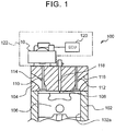
- FIG. 1 is a view of an internal combustion engine 100 according to the example mode, as will be described as the present example.
- the internal combustion engine 100 is an in-line four-cylinder internal combustion engine that is equipped with four cylinders (#1 to #4). The four cylinders are configured in the same manner.
- FIG. 1 is a view showing one of the cylinders in cross-section. Incidentally, although the number of cylinders herein is four, any number of cylinders may be provided.
- the internal combustion engine 100 is equipped with a cylinder block 102, a cylinder head 104, and a piston 106.
- the cylinder head 104 is provided on the cylinder block 102.
- the piston 106 is housed in the cylinder block 102 in such a manner as to be able to slide within a cylinder 102a that is formed in the cylinder block 102.
- a combustion chamber 108 is formed as a space that is surrounded by the cylinder block 102, the cylinder head 104, and the piston 106.
- the internal combustion engine 100 is equipped with an intake valve 110 and an exhaust valve 112 for each of the cylinders. Specifically, an intake port 114 that is provided with the intake valve 110, and an exhaust port 116 that is provided with the exhaust valve 112 are formed in the cylinder head 104.
- the cylinder head 104 is provided with a fuel injection valve 118 that injects fuel into the combustion chamber 108.
- the fuel injection valve 118 may be provided in such a manner as to inject fuel to the intake port 114 instead of injecting fuel into the combustion chamber 108.
- the internal combustion engine 100 is equipped with a variable valve device 122.
- the variable valve device 122 is equipped with a variable valve mechanism 10 and an electronic control unit (ECU) 120.
- ECU electronice control unit
- the variable valve mechanism 10 drives the intake valve 110.
- the variable valve mechanism 10 can change the working angle of the intake valve 110 while holding the maximum lift amount of the intake valve 110 constant.
- the variable valve mechanism 10 is controlled by the ECU 120.
- the ECU 120 is configured as a known digital computer having a bidirectional bus that connects a central processing unit (CPU), a random access memory (RAM), a read only memory (ROM) and input/output ports to one another.
- the ECU 120 exchanges signals with various sensors and actuators that are provided to control the internal combustion engine 100, thereby controlling the internal combustion engine.
- the ECU 120 performs the control regarding the driving of the intake valve 110 by the variable valve mechanism 10. In the present example in particular, the ECU 120 performs the control regarding the change in the working angle of the intake valve 110.
- the internal combustion engine 100 is also equipped with a drive cam for driving the exhaust valve 112.
- this drive cam is not needed to explain the present example, and hence is not depicted in FIG. 1 . Besides, the description of this drive cam will also be omitted.
- FIG. 2 is a perspective view of an entire configuration of the variable valve mechanism 10.
- FIG. 3 is a view showing a configuration around a drive camshaft 12 with which the variable valve mechanism 10 shown in FIG. 2 is equipped.
- FIG. 4 is a cross-sectional view taken along a line A-A of FIG. 2 .
- FIG. 5 is a view of the variable valve mechanism 10 as viewed from a direction indicated by an arrow B in FIG. 2 . Incidentally, in FIG. 5 , a guide member 36, which will be described later, is not shown.
- variable valve mechanism 10 is equipped with the drive camshaft 12.
- the drive camshaft 12 is coupled to a crankshaft (not shown) via a timing pulley 14 and a timing chain (not shown), and is configured to rotate at a speed of 1/2 of the crankshaft.
- VVT variable valve timing
- a variable valve timing (VVT) mechanism 16 capable of changing the rotational phase of the drive camshaft 12 with respect to rotation of the crankshaft is interposed between the drive camshaft 12 and the timing pulley 14.
- the drive camshaft 12 is fitted with cam pieces 18 for cylinders respectively.
- the cam pieces 18 are concentric with the drive camshaft 12, and are rotatably supported by the drive camshaft 12.
- Two driven cam lobes 18a for driving valves are formed on each of the cam pieces 18.
- Each of the driven cam lobes 18a is equipped with an arc-like base circle portion 18a1 that is concentric with the drive camshaft 12, and a nose portion 18a2 that is formed by protruding part of the base circle radially outward.
- a rocker arm (not shown) is provided for each intake valve 110 below each of the driven cam lobes 18a. The intake valve 110 is pushed out to be opened at a timing when the nose portion 18a2 of each of the driven cam lobes 18a comes into abutment on the rocker arm.
- the drive camshaft 12 is fitted with drive arms 20 for the cylinders respectively.
- Each of the drive arms 20 has a drive arm portion 20a that protrudes radially outward of the drive camshaft 12.
- Each of the drive arms 20 is integrally fixed to the drive camshaft 12 through the use of a predetermined fixation member (not shown).
- a driven arm portion 18b which protrudes radially outward of the drive camshaft 12, is formed integrally with each of the cam pieces 18, in the vicinity of the driven cam lobe 18a that is closer to the drive arm 20 for the same
- one end of a drive link 24 is rotatably coupled to the drive arm portion 20a via a camshaft-side rotary shaft 22.
- one end of a driven link 28 is rotatably coupled to the driven arm portion 18b via a cam lobe-side rotary shaft 26.
- variable valve mechanism 10 is equipped with the drive arm portion 20a and the driven arm portions 18b, which have an axial center of the drive camshaft 12 as a common rotation center, and a link mechanism 35 that is coupled by the drive link 24 and the driven link 28.
- the link mechanism 35 is a four-node link.
- the driven link 28 is arranged in front of the drive link 24 in a rotational direction C of the drive camshaft 12, with the control roller 32 interposed between the driven link 28 and the drive link 24.
- the link plate 34 is molded by bending two annularly formed plate portions concentrically with each other. Then, the link plate 34 is arranged such that the drive camshaft 12 penetrates the inside thereof. Furthermore, the link plate 34 is arranged on the control roller-side rotary shaft 30, with the two plate portions of the link plate 34 sandwiching the control roller 32.
- a raceway surface 36a1 of the guide member 36 is arranged on an outer peripheral side of the link plate 34, in such a manner as to cover the link plate 34.
- This raceway surface 36a1 is constituted by a circumferential surface.
- the control roller 32 is rotatably supported by the control roller-side rotary shaft 30 at a position (a tangent point P) that is in contact with the raceway surface 36a1.
- the control roller 32 moves while rolling along the raceway surface 36a1, in such a manner as to interlock with rotation of the drive camshaft 12.
- two retention rollers 38 as well as the control roller 32 are rotatably fitted between the plate portions of the link plate 34 via retention rotary shafts 40, at positions that are in contact with the raceway surface 36a1.
- the position of the link plate 34 in the radial direction of the drive camshaft 12 is defined by the raceway surface 36a1.
- the position of the control roller 32, which is fitted to the link plate 34, on the raceway surface 36a1 is defined.
- the control roller 32 moves while rolling on the raceway surface 36a1 constantly in contact with the raceway surface 36a1, as the drive camshaft 12 rotates.
- the relative position between the driven cam lobes 18a which are coupled to each other via the drive link 24 and the driven link 28, in the rotational direction is defined.
- the guide member 36 is equipped with annular portions 36a for the cylinders respectively.
- Each of the annular portions 36a has the raceway surface 36a1.
- the annular portions 36a of the respective cylinders are integrally coupled to one another by being bridged by bridge portions 36b.
- the guide member 36 is supported by the cylinder head 104 via a predetermined support member (not shown).
- the guide member 36 is configured to be movable in a direction indicated by an arrow D in FIG. 4 (which coincides with an axial direction of the cylinders of the internal combustion engine 100), and is bound in a direction perpendicular to the direction indicated by the arrow D.
- the variable valve mechanism 10 is equipped with an actuator 42.
- the actuator 42 moves the guide member 36 in the direction indicated by the arrow D in FIG. 4 , within a predetermined moving range. More specifically, the actuator 42 moves the guide member 36 such that a center point of the raceway surface 36a1 as the circumferential surface moves along a direction normal to the axis of the drive camshaft 12 and the axial direction of the cylinders. At this time, a state where the center point of the raceway surface 36a1 and a center point of the drive camshaft 12 coincide with each other as viewed from the axial direction of the drive camshaft 12 is regarded as "a reference state".
- the actuator 42 adjusts the movement of the guide member 36 to an arbitrary position within the moving range.
- the actuator 42 moves the guide member 36 on the basis of a command of the ECU 120.
- the actuator 42 may be configured by combining, for example, a motor, a worm gear with each other.
- FIG. 6 is a view showing how the raceway surface 36a1 of the guide member 36 has been displaced.
- FIG. 6 (a) shows a position of the raceway surface 36a1 in the reference state.
- FIG. 6 (b) shows a position of the raceway surface 36a1 at a time when the guide member 36 has moved upward with respect to the reference state.
- FIG. 6 (c) shows a position of the raceway surface 36a1 at a time when the guide member 36 has moved downward with respect to the reference state.
- the state shown in FIG. 6 (b) shows a state where the raceway surface 36a1 has moved upward (away from the combustion chamber 108).
- this state almost in a lower-half section of the raceway surface 36a1, as the control roller 32 moves toward a position P 0 directly below the raceway surface 36a1, the distance between the rotation center of the drive camshaft 12 and the rotation center of the control roller 32 is narrowed with respect to the aforementioned reference state.
- the cam lobe-side rotary shaft 26 moves forward in the rotational direction with respect to the reference state.
- the driven arm portion 18b moves faster than the drive arm portion 20a. That is, when the control roller 32 passes a lower semicircle of the raceway surface 36a1, the moving speed of the driven cam lobe 18a increases.
- the state shown in FIG. 6 (c) shows a state where the raceway surface 36a1 has moved downward (toward the combustion chamber 108).
- the distance between the rotation center of the drive camshaft 12 and the rotation center of the control roller 32 is widened with respect to the aforementioned reference state.
- the cam lobe-side rotary shaft 26 moves backward in the rotational direction with respect to the reference state.
- the driven arm portion 18b moves more slowly than the drive arm portion 20a.
- the moving speed of the driven cam lobe 18a decreases. In this manner, by appropriately controlling the position of the raceway surface 36a1, the moving speed of the driven cam lobe 18a (i.e., the cam piece 18) during one turn can be changed.
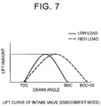
- FIG. 7 is a view showing a lift curve of the intake valve 110 in the present example mode
- a solid line in the drawing indicates a lift curve in the case where the working angle is reduced, and a broken line indicates a lift curve in the case where the working angle is increased.
- the variable valve mechanism 10 changes the rotational speed of each of the cam pieces 18 during one turn of that cam piece 18, thereby making it possible to change the working angle of the intake valve 110 (a time from the opening of the valve to the closing of the valve). That is, if the rotational speed of the cam piece 18 is increased in a period in which the nose portion 18a2 of the cam piece 18 acts on the intake valve 110, the working angle of the intake valve 110 decreases. On the contrary, if the rotational speed of the cam piece 18 is reduced in a period in which the nose portion 18a2 acts on the intake valve 110, the working angle of the intake valve 110 increases.
- variable valve mechanism 10 can change the working angle of the intake valve 110 while holding the maximum lift amount of the intake valve 110 constant.
- the variable valve mechanism 10 may change the timing for opening the intake valve 110 and the timing for closing the intake valve 110 by the VVT 16, without changing the lift curve.
- the timing for opening the intake valve 110 means a time point when the intake valve in its closed state starts opening
- the timing for closing the intake valve 110 means a time point when the intake valve in its open state closes to block a flow channel.
- variable valve mechanism 50 according to a comparative mode is a mechanism that changes the working angle of a valve by changing the lift amount of the valve.
- the variable valve mechanism 50 according to the comparative mode can be mounted on the internal combustion engine 100 described in the example mode.
- FIGS. 8 and 9 are views showing the outline of the variable valve mechanism 50 according to the comparative mode.
- FIG. 8 shows a configuration at a time when the lift amount of an intake valve 68 is reduced.
- FIG. 9 shows a configuration at a time when the lift amount of the intake valve 68 is increased. Both FIG. 8 (a) and FIG. 9 (a) show a state where the intake valve 68 is closed, and both FIG. 8 (b) and FIG.
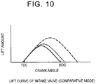
- FIG. 10 is a view showing a lift curve in the case where the lift amount of the intake valve 68 by the variable valve mechanism 50 is changed.
- a dotted line in FIG. 10 indicates the lift curve of the intake valve in the reference state
- a solid line in FIG. 10 indicates a case where the lift amount of the intake valve 68 is reduced
- a broken line in FIG. 10 indicates a case where the lift amount of the intake valve 68 is increased.
- the variable valve mechanism 50 is equipped with a camshaft 52, a control shaft 56, and a rocker arm 66.
- the camshaft 52 is a shaft that is coupled to a crankshaft (not shown) of the internal combustion engine via a timing pulley (not shown), a timing chain (not shown) and the like and rotates.
- the camshaft 52 is provided with cams 54 for the cylinders respectively.
- the control shaft 56 is a shaft that is provided parallel to the camshaft 52.
- the control shaft 56 is provided with roller arms 58 and rocking arms 62 for the cylinders respectively.
- a main roller 60 is provided at a tip of each of the roller arms 58.
- the camshaft 52 and the control shaft 56 are arranged such that the main rollers 60 are in contact with the cams 54 respectively.
- the roller arms 58 and the rocking arms 62 are provided on the control shaft 56 such that the relative position thereof around the control shaft 56 can be changed.
- the control shaft 56 is provided with rotation means (not shown) for rotating the roller arms 58 relatively to the rocking arms 62 respectively.
- the rocking arms 62 have slide surfaces 64 that are in contact with rocker arms 66 respectively.
- Each of the rocker arms 66 is configured to rotate upon receiving a force from a corresponding one of the rocking arms 62, and to drive the intake valve 68.
- variable valve mechanism 50 changes the lift amount of the intake valve 68.
- the variable valve mechanism 50 rotates the roller arms 58 to change an angle ⁇ formed by each of the roller arms 58 and a corresponding one of the rocking arms 62.
- the timing for opening the intake valve 68 is not changed. For example, if the angle ⁇ formed by the roller arm 58 and the rocking arm 62 is narrowed, the lift amount of the intake valve 68 decreases as indicated by the solid line in FIG. 10 .
- the timing for closing the intake valve 68 is advanced, and the working angle of the intake valve 68 decreases.
- variable valve mechanism 50 changes the working angle of the intake valve 68 by changing the lift amount of the intake valve 68.
- FIG. 11 is a view making a comparison between the example mode and the comparative mode as to changes in the specification of the internal combustion engine 100 with respect to the timings for closing the intake valves 110 and 68.
- FIG. 11 (a) is a view showing the comparison as to the maximum lift amounts of the intake valves 110 and 68.
- FIG. 11 (b) is a view showing the comparison as to a geometric volume in each cylinder, which is defined by the cylinder block 102, the cylinder head 104, and the piston 106, at the timings (IVC) for closing the intake valves 110 and 68.
- FIG. 11 is a view making a comparison between the example mode and the comparative mode as to changes in the specification of the internal combustion engine 100 with respect to the timings for closing the intake valves 110 and 68.
- FIG. 11 (a) is a view showing the comparison as to the maximum lift amounts of the intake valves 110 and 68.
- FIG. 11 (b) is a view showing the comparison as to a geometric volume in each
- FIG. 11 (c) is a view showing the comparison as to a volumetric efficiency.
- FIG. 11 (d) is a view showing the comparison as to an actual compression ratio.
- a solid line indicates a value in the example mode, and a broken line indicates a value in the comparative mode.
- FIGS. 11 (b) and 11 (d) since the value in the example mode and the value in the comparative mode are equal to each other, no broken line is depicted.
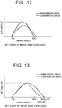
- FIG. 12 is a view making a comparison between the lift curve of the intake valve 110 according to the example mode and the lift curve of the intake valve 68 according to the comparative mode during low-load operation.
- FIG. 13 is a view making a comparison between the lift curve of the intake valve according to the example mode and the lift curve of the intake valve according to the comparative mode during high-load operation.
- the example mode is configured such that the maximum lift amount of the intake valve 110 coincides with a maximum lift amount at a time when the lift amount of the intake valve 68 is maximized in the comparative mode. Accordingly, as shown in FIG. 11 (a) , the maximum lift amount of the intake valve in the example mode is always equal to or larger than the maximum lift amount of the intake valve according to the comparative mode, independently of the timing for closing the intake valve.
- the internal combustion engine 100 requires valve characteristics in which the working angle of the intake valve 110 or 68 is reduced during low-load operation and the working angle of the intake valve 110 or 68 is enlarged during high-load operation.
- the timing for opening the intake valve 110 or 68 is constant regardless of the load of the internal combustion engine 100. More specifically, the timing for opening the intake valve 110 or 68 is set as the vicinity of a top dead center (TDC). Accordingly, in the case where the working angle is enlarged, the timing for closing the intake valve 110 or 68 is made later (retarded).
- the amount of fuel supplied into the cylinders is small, so a fluctuation in the actual compression ratio of the internal combustion engine leads to a fluctuation in combustion.
- the actual compression ratio fluctuates. For example, if the actual compression ratio decreases when the load is low, the amount of air taken into the cylinders decreases to possibly cause misfire or a decrease in output.
- the actual compression ratio is obtained by dividing the volume of the combustion chamber during compression by the volume of the combustion chamber at the timing for closing the intake valve. Since the volume of the combustion chamber during compression is constant, the actual compression ratio depends on the volume of the combustion chamber at the timing for closing the intake valve. Thus, as shown in FIGS. 11 (b) and 11 (d) , the actual compression ratio changes in the same manner as the geometric volume in the cylinder 102a that is defined by the cylinder block 102, the cylinder head 104, and the piston 106 at the timing (IVC) for closing the intake valve.
- the geometric volume in the cylinder 102a is maximized and the fluctuation in the geometric volume is also small in the case where the piston is located at a bottom dead center (BDC). Accordingly, as shown in FIG. 11 (d) , the fluctuation in the actual compression ratio is also minimized in the vicinity of the bottom dead center (BDC) of the piston.
- variable valve device 122 according to the example mode does not cause a decrease in the maximum lift amount of the intake valve 110 even if the timing for closing the intake valve 110 is set as the vicinity of the bottom dead center.
- the variable valve device 122 according to the example mode makes it possible to obtain higher volumetric efficiency than in the case of the comparative mode. This is because the variable valve device 122 according to the example mode can change the working angle of the intake valve 110 while holding the maximum lift amount of the intake valve 110 constant. Since the volumetric efficiency can thus be restrained from decreasing, the variable valve device 122 according to the example mode allows the intake valve 110 to be closed in the vicinity of the bottom dead center. As a result, even in the case where the working angle of the intake valve 110 has changed due to manufacturing variability or aged deterioration, the fluctuation in the actual compression ratio resulting from a change in the working angle can be reduced, and a stable combustion state can be realized.
- variable valve device 122 for the internal combustion engine 100 sets the timing for closing the intake valve 110 as the vicinity of the bottom dead center when the load is low. Specifically, it is preferable that the timing for closing the intake valve 110 be within 10°CA before and after the bottom dead center (BDC ⁇ 10°CA).
- the timing for closing the intake valve to realize the required volumetric efficiency ⁇ v1 during high-load operation is later in the example mode than in the comparative mode (the comparative mode of the invention: ABDC 40°CA, the embodiment mode of the invention: ABDC 50°CA).
- the actual compression ratio can be made lower in the example mode than in the comparative mode ( ⁇ 1 > ⁇ 2 ).
- the variable valve device 122 according to the example mode can curb the generation of smoke in the internal combustion engine 100.
- the actual compression ratio can be raised from ⁇ 2 to ⁇ 1 .
- the volumetric efficiency in the example mode can be raised to ⁇ v2 accordingly. Therefore, the example mode makes it possible to raise the output of the internal combustion engine 100 with respect to the comparative mode.
- variable valve device 122 for the internal combustion engine 100 retards the timing for closing the intake valve 110 with respect to the bottom dead center when the load is high. In other words, the variable valve device 122 retards the timing for closing the intake valve 110 when the load is high than when the load is low. It is preferable to retard the timing for closing the intake valve 110 to a maximum possible extent, while realizing the required volumetric efficiency ⁇ v1 during high-load operation. Furthermore, it is preferable to set the timing for closing the intake valve 110 as ABDC 50°CA. Incidentally, in the case where the volumetric efficiency is desired to be raised because of an insufficient amount of intake air taken into the combustion chamber etc., the timing for closing the intake valve 110 can also be advanced. For example, the timing for closing the intake valve may be set as ABDC 40°CA.
- the variable valve device 122 sets the timing for closing the intake valve 110 as a timing when the volumetric efficiency of the internal combustion engine 100 is maximized, when the load is intermediate.
- the volumetric efficiency is higher than in the comparative mode, so the generation amount of smoke can be held small.
- the timing for closing the intake valve 110 when the volumetric efficiency is maximized is a single point.
- the intake valve 110 may be closed in accordance with a timing when the volumetric efficiency and the actual compression ratio are optimized, in order to cope with cases where the actual compression ratio fluctuates.
- the timing for closing the intake valve during intermediate-load operation may be set by continuously changing the timing for closing the intake valve during a transition from low load to high load or during a transition in the opposite direction.
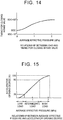
- the load and the timing for closing the intake valve 110 in the case where the timing for closing the intake valve 110 is continuously changed will be described herein with reference to FIGS. 14 to 16 .
- FIG. 14 is a view showing a relationship between the load of the internal combustion engine 100 and the timing for closing the intake valve 110.
- FIG. 15 is a view showing a relationship between the average effective pressure and the accelerator opening degree.
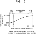
- FIG. 16 is a view showing the timing for closing the intake valve 110 with respect to the accelerator opening degree.
- FIG. 14 represents the load through the use of an average effective pressure Pme.
- the average effective pressure Pme is expressed by an expression (1) shown below.
- Pme Torque ⁇ 4 ⁇ / Displacement
- the variable valve device 122 for the internal combustion engine 100 continuously changes the timing for closing the intake valve 110 from low load to high load.
- the accelerator opening degree is 100% when the accelerator is fully open.
- the accelerator opening degree corresponding to a low-load region is set as 0 to 20%
- the accelerator opening degree corresponding to an intermediate region is set as 20 to 80%
- the accelerator opening degree corresponding to a high-load region is set as 80 to 100%.
- FIGS. 14 and 15 it is possible to set the timing for closing the intake valve 110 with respect to the accelerator opening degree as shown in FIG. 16 .
- variable valve device 122 for the internal combustion engine 100 retards the timing for closing the intake valve 110 and enlarges the working angle of the intake valve 110 as the load of the internal combustion engine 100 rises, while holding the timing for opening the intake valve 110 constant.
- the variable valve device 122 for the internal combustion engine 100 provides a driving guideline for changing the valve lift of the intake valve in accordance with the state of the load of the internal combustion engine 100.
- the variable valve device 122 for the internal combustion engine 100 sets the timing for closing the intake valve 110 as the vicinity of the bottom dead center when the load is low. As a result, the fluctuation in the actual compression ratio can be reduced, and a stable combustion state can be realized.
- variable valve device 122 retards the timing for closing the intake valve 110 with respect to the bottom dead center when the load is high. As a result, the generation amount of smoke in the internal combustion engine 100 can be reduced. Besides, the output of the internal combustion engine 100 can be raised.
- FIG. 17 is a view showing a first intake port 114a and a second intake port 114b of the internal combustion engine according to the present embodiment of the invention.
- FIG. 17 (a) is a perspective view of the first intake port 114a and the second intake port 114b.
- FIG. 17 (b) is a top view of the first intake port 114a and the second intake port 114b.
- the first intake port 114a is a tangential port.
- the tangential port introduces intake air into the combustion chamber 108 such that intake air flows in along a wall surface of the cylinder 102a of the combustion chamber 108.
- the first intake port 114a introduces intake air along the wall surface of the cylinder 102a, and generates a strong swirl current f 1 in the combustion chamber 108. As the flow rate of intake air supplied from this first intake port 114a increases, the intensity of the swirl current (swirl ratio) generated in the combustion chamber 108 is enhanced.
- the second intake port 114b is a helical port.
- the helical port is a spirally formed port, and supplies intake air to a central portion of the combustion chamber 108.
- the center of the combustion chamber 108 indicates a center of a cross-sectional circle at the time when the cylinder 102a is cut perpendicularly to an axis thereof.
- the second intake port 114b introduces a weak swirl current f 2 to the center of the combustion chamber 108.
- the intake air supplied from the second intake port 114b remains at the center in the combustion chamber 108, and is restrained from being diffused.
- the first intake port 114a is provided with a first intake valve 110a
- the second intake port 114b is provided with a second intake valve 110b.
- a variable valve mechanism (not shown) that drives the first intake valve 110a and the second intake valve 110b is provided.
- the variable valve mechanism according to the present embodiment of the invention is configured in the same manner as the variable valve mechanism 10 according to the above example.
- the variable valve mechanism according to the present embodiment of the invention is equipped with a first guide member for changing the rotational speed of only the cam piece acting on the first intake valve 110a, and a second guide member for changing the rotational speed of only the cam piece acting on the second intake valve 110b.
- variable valve mechanism drives the first intake valve 110a and the second intake valve 110b independently of each other.
- the variable valve mechanism according to the present embodiment of the invention can change the working angle of the first intake valve 110a while holding the maximum lift amount of the first intake valve 110a constant, and can change the working angle of the second intake valve 110b while holding the maximum lift amount of the second intake valve 110b constant.
- the first embodiment of the invention is identical in other configurational details to the above example. The same components as in the example are denoted by the same reference numerals respectively in the drawings, and the detailed description thereof will be omitted.
- the swirl ratio in the combustion chamber 108 is lowered from the standpoint of suppressing misfire and reducing the amount of unburned HC when the load is low, and the swirl ratio in the combustion chamber 108 is enhanced from the standpoint of discharging smoke when the load is high.
- the timing for closing the intake valve (the first intake valve 110a or the second intake valve 110b) is set as the vicinity of the bottom dead center (BDC) with a view to stabilizing the actual compression ratio, during low-load operation. Then, for the purpose of suppressing the generation of smoke, the timing for closing the intake valve (the first intake valve 110a or the second intake valve 110b) is set so as to be retarded as the load of the internal combustion engine rises.
- FIG. 18 is a view showing an example of a lift curve of a valve.
- a solid line in FIG. 18 is a graph indicating the lift curve of a valve that opens in the vicinity of a top dead center (TDC) and closes in the vicinity of the bottom dead center (BDC).
- a broken line in FIG. 18 is a graph indicating the lift curve of a valve that opens in the vicinity of the top dead center (TDC) and closes at a timing retarded by 50°CA from the bottom dead center (ABDC 50°CA).
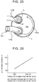
- FIG. 19 is a view showing a relationship between the timing for closing a valve and the speed of a piston at the time when the lift amount of the valve is maximized, in an internal combustion engine having the valve, which opens in the vicinity of the top dead center.
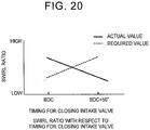
- FIG. 20 is a view showing the swirl ratio with respect to the timing for closing the intake valve.
- a solid line in FIG. 20 indicates an actual swirl ratio
- a dotted line in FIG. 20 indicates a required value.
- the lift amount of the valve is maximized in the vicinity of ATDC 90°CA (BBDC 90°CA).
- ATDC 90°CA the moving speed of the piston is the highest, so the intake speed is high. Accordingly, in this case, in the vicinity of ATDC 90°CA, the lift amount is large and the intake speed is high, so the amount of intake air sucked into the combustion chamber 108 is large.
- the first intake valve 110a opens in the vicinity of the top dead center (TDC), and closes in the vicinity of the bottom dead center (BDC) when the load is low.
- the first intake port 114a is a tangential port, the amount of intake air sucked into the combustion chamber 108 increases if the first intake valve 110a opens in the vicinity of the top dead center (TDC) and closes in the vicinity of the bottom dead center (BDC).
- a swirl current in the combustion chamber 108 is intensified, and the control guideline of lowering the swirl ratio when the load is low is contradicted.
- the first intake valve 110a opens in the vicinity of the top dead center (TDC) and closes at 50°CA after the bottom dead center (ABDC 50°CA) when the load is high.
- TDC top dead center
- ABDC 50°CA bottom dead center
- the lift amount of the first intake valve 110a is not maximized, so a sufficient amount of intake air cannot be sucked into the combustion chamber 108.
- s swirl is not sufficiently intensified, and the swirl ratio cannot be enhanced.
- FIG. 21 is a view showing lift curves of the first intake valve 110a and the second intake valve 110b.
- FIG. 21 (a) shows the lift curves at the time when the load is low
- FIG. 21 (b) shows the lift curves at the time when the load is high.
- a broken line indicates the lift curve of the first intake valve 110a
- a solid line indicates the lift curve of the second intake valve 110b.
- the maximum lift amount of the first intake valve 110a is set smaller than the maximum lift amount of the second intake valve 110b.
- the valve characteristics of the second intake valve 110b are the same as the valve characteristics of the intake valve 110 according to the above example.
- the variable valve device changes the valve-open period of the first intake valve 110a such that the crank angle at which the lift amount of the first intake valve 110a is maximized becomes smaller than the crank angle at which the speed of the piston is maximized, when the load of the internal combustion engine is low.
- the variable valve device shifts the time point when the lift amount of the first intake valve 110a is maximized, to a time point equal to or earlier than ATDC 90°CA.
- the variable valve device sets the time point when the lift amount of the first intake valve 110a is maximized, as ATDC 70°CA. At this time, the timing for opening the second intake valve 110b is in the vicinity of the TDC, and the timing for closing the second intake valve 110b is in the vicinity of the BDC. Thus, the time point when the lift amount of the second intake valve 110b is maximized is in the vicinity of ATDC 90°CA.
- the time point when the lift amount of the first intake valve 110a is maximized deviates from the vicinity of ATDC 90°CA where the intake speed is maximized.
- intake air is restrained from being taken into the combustion chamber 108 from the first intake port 114a.
- the time point when the lift amount of the second intake valve 110b is maximized is in the vicinity of ATDC 90°CA where the intake speed is maximized.
- the amount of intake air taken into the combustion chamber 108 from the second intake port 114b increases.
- the lift amount of the first intake valve 110a is smaller than the lift amount of the second intake valve 110b
- the interior of the combustion chamber 108 is dominated by intake air from the second intake port 114b.
- the second intake port 114b is a helical port. Therefore, the interior of the combustion chamber 108 is dominated by intake air from the helical port, and the swirl ratio in the combustion chamber 108 is lowered.
- the valve characteristics of the second intake valve 110b are the same as the valve characteristics of the intake valve 110 according to the above example.
- the variable valve device changes the valve-open period of the first intake valve 110a such that the crank angle at which the lift amount of the first intake valve 110a is maximized becomes equal to the crank angle at which the speed of the piston is maximized, when the load of the internal combustion engine is high.
- the variable valve device sets the time point when the lift amount of the first intake valve 110a is maximized, as the vicinity of ATDC 90°CA. More specifically, the variable valve device sets the time point when the lift amount of the first intake valve 110a is maximized, as ATDC 90 ⁇ 10°CA.
- the timing for closing the first intake valve 110a it is preferable to retard the timing for closing the first intake valve 110a to a maximum possible extent.
- the timing when the lift amount is maximized is determined as described above. Therefore, if the timing for closing the first intake valve 110a is retarded, the timing for opening the first intake valve 110a is advanced with respect to the TDC.
- the timing for opening the second intake valve 110b is in the vicinity of the TDC, and the timing for closing the second intake valve 110b is ABDC 50°CA.
- the time point when the lift amount of the second intake valve 110b is maximized deviates from the vicinity of ATDC 90°CA.
- the time point when the lift amount of the first intake valve 110a is maximized is in the vicinity of ATDC 90°CA where the intake speed is maximized.
- the amount of intake air taken into the combustion chamber 108 from the first intake port 114a increases.
- the time point when the lift amount of the second intake valve 110b is maximized deviates from the vicinity of ATDC 90°CA where the intake speed is maximized.
- intake air is restrained from being taken into the combustion chamber 108 from the second intake port 114b.
- the lift amount of the first intake valve 110a is smaller than the lift amount of the second intake valve 110b.
- the amount of intake air taken in from the first intake port 114a as a tangential port is large, so a swirl in the combustion chamber 108 is intensified.
- the first intake valve 110a opens earlier than the second intake valve 110b, so a swirl current is intensified.
- FIG. 22 is a view showing the swirl ratio in the combustion chamber 108 with respect to the timing for closing the second intake valve 110b.
- the swirl ratio is enhanced as the timing for closing the second intake valve 110b is retarded. That is, as soon as the timing for closing the second intake valve 110b becomes equal to the BDC, the time point when the lift amount of the first intake valve 110a is maximized becomes the earliest (is most advanced). Then, the time point when the lift amount of the first intake valve 110a is maximized is set so as to become equal to ATDC 90°CA, as soon as the working angle of the second intake valve 110b is maximized (at the timing for closing the second intake valve 110b, ABDC 50°CA).
- variable valve device for the internal combustion engine according to the present embodiment of the invention can lower the swirl ratio when the load is low, and can suppress misfire of the internal combustion engine and reduce the amount of unburned HC.
- variable valve device for the internal combustion engine according to the present embodiment of the invention makes it possible to stabilize the actual compression ratio at the time when the load is low, and suppress a fluctuation in combustion, by setting the valve characteristics of the second intake valve 110b the same as in the above example.
- the variable valve device for the internal combustion engine according to the present embodiment of the invention can enhance the swirl ratio in the combustion chamber 108 and reduce the discharge amount of smoke.
- the variable valve device for the internal combustion engine according to the present embodiment of the invention can lower the actual compression ratio at the time when the load is high, and suppress the generation of smoke, by setting the valve characteristics of the second intake valve 110b the same as in the above example.
- the internal combustion engine according to the present embodiment of the invention is substantially identical in configuration to the internal combustion engine according to the first embodiment of the invention.
- the present embodiment of the invention is different in the lift curve of the first intake valve 110a from the above example and the first embodiment of the invention.
- the present embodiment of the invention is identical in other configurational details to the first embodiment of the invention. The detailed description of the same configurational details as in the first embodiment of the invention will be omitted.
- components identical to those of the first embodiment of the invention are denoted by the same reference numerals respectively.
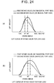
- FIG. 24 is a view showing the lift curves according to the present embodiment of the invention.
- FIG. 24 (a) shows the lift curves at the time when the load is low
- FIG. 24 (b) shows the lift curves at the time when the load is high.
- a broken line indicates the lift curve of the first intake valve 110a
- a solid line indicates the lift curve of the second intake valve 110b.
- the lift amount of the first intake valve 110a is set so as to be maximized in the first half of the valve-open period.
- the crank angle at the time when the lift amount is maximized is advanced with respect to the crank angle as an intermediate value between the timing for opening the first intake valve 110a and the timing for closing the first intake valve 110a.
- the crank angle at which the maximum lift amount is reached is equal to ATDC 70°CA.
- the timing for closing the second intake valve 110b is retarded as the load rises.
- the timing for opening the second intake valve 110b is in the vicinity of the TDC, and the timing for closing the second intake valve 110b is equal to ABDC 50°CA.
- both the first intake valve 110a and the second intake valve 110b have the valve characteristics in which the working angle thereof changes while the maximum lift amount thereof is held constant.
- the internal combustion engine according to the present embodiment of the invention is substantially identical in configuration to the internal combustion engine according to the first embodiment of the invention.
- the present embodiment of the invention is different from the first embodiment of the invention in that the first intake port 114a is equipped with a swirl control valve (SCV) 124.
- SCV swirl control valve
- the lift curves of the first intake valve 110a and the second intake valve 110b are different from those of the first embodiment of the invention.
- the third embodiment of the invention is identical in other configurational details to the first embodiment of the invention.
- components identical to those of the first embodiment of the invention are denoted by the same reference numerals respectively, and the detailed description thereof will be omitted.
- FIG. 1 components identical to those of the first embodiment of the invention are denoted by the same reference numerals respectively, and the detailed description thereof will be omitted.
- variable valve device for the internal combustion engine according to the present embodiment of the invention drives the first intake valve 110a and the second intake valve 110b according to the same guideline as in the above example, and hence suppresses a fluctuation in the actual compression ratio and stabilizes the state of combustion when the load is low.
- variable valve device for the internal combustion engine according to the present embodiment of the invention reduces the actual compression ratio and suppresses the generation of smoke when the load is high.
- the variable valve device for the internal combustion engine according to the present embodiment of the invention lowers the swirl ratio by the SCV 124, and hence suppresses misfire and reduces the generation of unburned HC when the load is low.
- the variable valve device for the internal combustion engine according to the present embodiment of the invention enhances the swirl ratio and hence suppresses the generation of smoke when the load is high.
Landscapes
- Engineering & Computer Science (AREA)
- Mechanical Engineering (AREA)
- General Engineering & Computer Science (AREA)
- Chemical & Material Sciences (AREA)
- Combustion & Propulsion (AREA)
- Valve Device For Special Equipments (AREA)
- Output Control And Ontrol Of Special Type Engine (AREA)
Claims (10)
- Variable Ventilvorrichtung (122) für einen Verbrennungsmotor (100), die eine Tangentialöffnung (114a) umfasst, die dafür konfiguriert ist, Ansaugluft entlang einer Wandfläche eines Zylinders (102a) einer Brennkammer (108) des Verbrennungsmotors (100) einzuleiten, und eine Spiralöffnung (114b), die dafür konfiguriert ist, Ansaugluft dem mittleren Teil einer Brennkammer (108) des Verbrennungsmotors (100) zuzuführen, wobei:ein maximaler Hubbetrag eines ersten Einlassventils (110a), das in der Tangentialöffnung (114a) vorgesehen ist, kleiner ist als ein maximaler Hubbetrag eines zweiten Einlassventils (110b), das in der Spiralöffnung (114b) vorgesehen ist;die variable Ventilvorrichtung (122) für Folgendes konfiguriert ist:Ändern eines Zeitpunkts zum Schließen des ersten Einlassventils (110a), so dass ein Kurbelwinkel, bei dem ein Hubbetrag des ersten Einlassventils (110a) maximiert wird, kleiner wird als ein Kurbelwinkel, bei dem die Geschwindigkeit eines Kolbens maximiert wird, wenn die Last des Verbrennungsmotors (100) gering ist, und/oderÄndern eines Zeitpunkts zum Schließen des ersten Einlassventils (110a), so dass ein Kurbelwinkel, bei dem ein Hubbetrag des ersten Einlassventils (110a) maximiert wird, gleich einem Kurbelwinkel wird, bei dem die Geschwindigkeit eines Kolbens maximiert wird, wenn die Last des Verbrennungsmotors (100) hoch ist;wobei die variable Ventilvorrichtung (122) des Weiteren einen variablen Ventilmechanismus (10) umfasst, der einen Arbeitswinkel des zweiten Einlassventils (110b) ändern kann, während ein maximaler Hubbetrag des zweiten Einlassventils (110b) konstant gehalten wird; und
wobei die variable Ventilvorrichtung (122) dafür konfiguriert ist, einen Zeitpunkt zum Schließen des zweiten Einlassventils (110b) zu verzögern, wenn eine Last des Verbrennungsmotors (100) ansteigt, und den Arbeitswinkel zu vergrößern, während ein Zeitpunkt zum Öffnen des zweiten Einlassventils (110b) und der maximale Hubbetrag des zweiten Einlassventils (110b) konstant gehalten werden. - Variable Ventilvorrichtung (122) für den Verbrennungsmotor (100) nach Anspruch 1, gekennzeichnet durch
Einstellen des Zeitpunkts zum Schließen des zweiten Einlassventils (110b) in der Nähe eines unteren Totpunkts, wenn die Last des Verbrennungsmotors (100) niedrig ist. - Variable Ventilvorrichtung (122) für den Verbrennungsmotor (100) nach Anspruch 1 oder 2, gekennzeichnet durch
Verzögern des Zeitpunkts zum Schließen des zweiten Einlassventils (110b) in Bezug auf die Nähe des unteren Totpunkts, wenn die Last des Verbrennungsmotors (100) hoch ist. - Variable Ventilvorrichtung (122) für den Verbrennungsmotor (100) nach einem der Ansprüche 1 bis 3, gekennzeichnet durch
Ändern des Zeitpunkts zum Schließen des zweiten Einlassventils (110b), so dass ein volumetrischer Wirkungsgrad maximiert wird, wenn die Last des Verbrennungsmotors (100) in einem mittleren Bereich liegt. - Variable Ventilvorrichtung (122) für den Verbrennungsmotor (100) nach einem der Ansprüche 1 bis 4, dadurch gekennzeichnet, dass
der variable Ventilmechanismus (10) einen Arbeitswinkel des ersten Einlassventils (110a) ändern kann, während ein maximaler Hubbetrag des ersten Einlassventils (110a) konstant gehalten wird; und
wobei die variable Ventilvorrichtung (122) dafür konfiguriert ist, einen Zeitpunkt zum Schließen des ersten Einlassventils (110a) zu verzögern, wenn eine Last des Verbrennungsmotors (100) ansteigt, und den Arbeitswinkel zu vergrößern, während ein Zeitpunkt zum Öffnen des ersten Einlassventils (110a) und der maximale Hubbetrag des ersten Einlassventils (110a) konstant gehalten werden. - Variable Ventilvorrichtung (122) für den Verbrennungsmotor (100) nach einem der Ansprüche 1 bis 5, gekennzeichnet durch
Einstellen des Zeitpunkts zum Schließen des ersten Einlassventils (110a) in der Nähe eines unteren Totpunkts, wenn die Last des Verbrennungsmotors (100) niedrig ist. - Variable Ventilvorrichtung (122) für den Verbrennungsmotor (100) nach einem der Ansprüche 1 bis 6, gekennzeichnet durch
Verzögern des Zeitpunkts zum Schließen des ersten Einlassventils (110a) in Bezug auf die Nähe des unteren Totpunkts, wenn die Last des Verbrennungsmotors (100) hoch ist. - Variable Ventilvorrichtung (122) für den Verbrennungsmotor (100) nach einem der Ansprüche 1 bis 7, gekennzeichnet durch
Ändern des Zeitpunkts zum Schließen des ersten Einlassventils (110a), so dass ein volumetrischer Wirkungsgrad maximiert wird, wenn die Last des Verbrennungsmotors (100) in einem mittleren Bereich liegt. - Variable Ventilvorrichtung (122) für den Verbrennungsmotor (100) nach einem der Ansprüche 1 bis 8, dadurch gekennzeichnet, dass
der Hubbetrag des ersten Einlassventils (110a) so eingestellt ist, dass er in einer ersten Hälfte einer Ventilöffnungsperiode maximiert wird. - Variable Ventilvorrichtung (122) für den Verbrennungsmotor (100) nach einem der Ansprüche 1 bis 9, dadurch gekennzeichnet, dass
die Tangentialöffnung (114a) mit einem Drallsteuerventil (124) ausgestattet ist, das einen Drallstrom einstellt.
Applications Claiming Priority (1)
| Application Number | Priority Date | Filing Date | Title |
|---|---|---|---|
| PCT/JP2012/057474 WO2013140596A1 (ja) | 2012-03-23 | 2012-03-23 | 内燃機関の可変動弁装置 |
Publications (3)
| Publication Number | Publication Date |
|---|---|
| EP2829709A1 EP2829709A1 (de) | 2015-01-28 |
| EP2829709A4 EP2829709A4 (de) | 2016-01-27 |
| EP2829709B1 true EP2829709B1 (de) | 2020-12-23 |
Family
ID=49222090
Family Applications (1)
| Application Number | Title | Priority Date | Filing Date |
|---|---|---|---|
| EP12871936.6A Not-in-force EP2829709B1 (de) | 2012-03-23 | 2012-03-23 | Variable ventilvorrichtung für einen verbrennungsmotor |
Country Status (9)
| Country | Link |
|---|---|
| US (1) | US9546607B2 (de) |
| EP (1) | EP2829709B1 (de) |
| JP (1) | JP5825425B2 (de) |
| CN (1) | CN104204472B (de) |
| AU (1) | AU2012374402B2 (de) |
| BR (1) | BR112014023629B1 (de) |
| IN (1) | IN2014DN07945A (de) |
| RU (1) | RU2594395C2 (de) |
| WO (1) | WO2013140596A1 (de) |
Families Citing this family (6)
| Publication number | Priority date | Publication date | Assignee | Title |
|---|---|---|---|---|
| JP6604350B2 (ja) * | 2017-03-22 | 2019-11-13 | トヨタ自動車株式会社 | 内燃機関 |
| US10358988B2 (en) * | 2017-03-27 | 2019-07-23 | Kabushiki Kaisha Toyota Chuo Kenkyusho | Internal combustion engine |
| DE102017130977A1 (de) * | 2017-12-21 | 2019-06-27 | Volkswagen Aktiengesellschaft | Brennkraftmaschine mit vier Zylindern und Verfahren zum Betreiben einer solchen Brennkraftmaschine |
| WO2022113511A1 (ja) * | 2020-11-30 | 2022-06-02 | 日立Astemo株式会社 | バルブ制御装置及びバルブ制御方法 |
| CN115263574A (zh) * | 2022-06-28 | 2022-11-01 | 东风汽车集团股份有限公司 | 一种压燃发动机控制方法及相关设备 |
| CN119737223B (zh) * | 2024-12-31 | 2025-10-24 | 潍柴动力股份有限公司 | 发动机的进气组件、发动机、车辆和发动机的进气控制方法 |
Family Cites Families (24)
| Publication number | Priority date | Publication date | Assignee | Title |
|---|---|---|---|---|
| RU2028470C1 (ru) * | 1990-04-27 | 1995-02-09 | Центральный научно-исследовательский дизельный институт | Регулируемый спиральный впускной канал в головке цилиндра двигателя внутреннего сгорания |
| JP3551435B2 (ja) * | 1992-09-29 | 2004-08-04 | マツダ株式会社 | 過給機付エンジン |
| JPH08260925A (ja) | 1995-03-24 | 1996-10-08 | Nissan Motor Co Ltd | エンジンの吸気システム |
| JP3799944B2 (ja) * | 2000-03-21 | 2006-07-19 | トヨタ自動車株式会社 | 内燃機関の可変動弁機構および吸気量制御装置 |
| JP2003083118A (ja) | 2001-09-10 | 2003-03-19 | Toyota Motor Corp | 2サイクル自着火ガソリンエンジン |
| JP2004353485A (ja) | 2003-05-27 | 2004-12-16 | Toyota Motor Corp | 予混合圧縮着火燃焼内燃機関の吸気制御方法 |
| JP4506414B2 (ja) * | 2004-10-29 | 2010-07-21 | トヨタ自動車株式会社 | 内燃機関のバルブ特性制御装置 |
| JP4124224B2 (ja) * | 2005-11-14 | 2008-07-23 | トヨタ自動車株式会社 | 4サイクル予混合圧縮自着火式内燃機関の制御装置 |
| JP2006336659A (ja) | 2006-09-20 | 2006-12-14 | Hitachi Ltd | 内燃機関の可変動弁装置 |
| JP4850744B2 (ja) * | 2007-02-13 | 2012-01-11 | 日立オートモティブシステムズ株式会社 | 内燃機関の吸気制御装置 |
| JP4907416B2 (ja) * | 2007-04-23 | 2012-03-28 | 日立オートモティブシステムズ株式会社 | 内燃機関の可変動弁装置 |
| JP2008303773A (ja) * | 2007-06-07 | 2008-12-18 | Hitachi Ltd | 内燃機関の可変動弁装置 |
| JP4459989B2 (ja) * | 2007-07-30 | 2010-04-28 | 三菱自動車工業株式会社 | 可変動弁機構付のエンジン |
| JP2009156029A (ja) * | 2007-12-25 | 2009-07-16 | Hitachi Ltd | 内燃機関の可変動弁システム及び該可変動弁システムに用いられるコントローラ |
| JP2009299655A (ja) | 2008-06-17 | 2009-12-24 | Toyota Motor Corp | 内燃機関の動弁システム |
| JP2010059791A (ja) * | 2008-09-01 | 2010-03-18 | Hitachi Automotive Systems Ltd | 可変動弁機構の制御装置及び可変動弁制御システム |
| JP2010121567A (ja) * | 2008-11-20 | 2010-06-03 | Toyota Motor Corp | 内燃機関の制御装置 |
| JP2010121597A (ja) | 2008-11-21 | 2010-06-03 | Toyota Motor Corp | 尿素水溶液の分散装置 |
| JP5099374B2 (ja) * | 2009-02-23 | 2012-12-19 | 三菱自動車工業株式会社 | 可変動弁装置付エンジン |
| JP5108811B2 (ja) | 2009-03-24 | 2012-12-26 | 日立オートモティブシステムズ株式会社 | 車両用内燃機関の可変動弁装置 |
| JP2010236434A (ja) | 2009-03-31 | 2010-10-21 | Toyota Motor Corp | 吸気量制御装置 |
| JP5227265B2 (ja) * | 2009-06-04 | 2013-07-03 | 本田技研工業株式会社 | 排気過給機を備える内燃機関 |
| JP5302173B2 (ja) * | 2009-12-07 | 2013-10-02 | 日立オートモティブシステムズ株式会社 | 内燃機関の可変動弁装置 |
| JP5654940B2 (ja) * | 2011-04-21 | 2015-01-14 | 日立オートモティブシステムズ株式会社 | 可変動弁装置のコントローラ及び内燃機関の可変動弁装置 |
-
2012
- 2012-03-23 JP JP2014505923A patent/JP5825425B2/ja not_active Expired - Fee Related
- 2012-03-23 AU AU2012374402A patent/AU2012374402B2/en not_active Ceased
- 2012-03-23 WO PCT/JP2012/057474 patent/WO2013140596A1/ja not_active Ceased
- 2012-03-23 CN CN201280071714.0A patent/CN104204472B/zh not_active Expired - Fee Related
- 2012-03-23 EP EP12871936.6A patent/EP2829709B1/de not_active Not-in-force
- 2012-03-23 US US14/387,296 patent/US9546607B2/en active Active
- 2012-03-23 IN IN7945DEN2014 patent/IN2014DN07945A/en unknown
- 2012-03-23 BR BR112014023629-1A patent/BR112014023629B1/pt not_active IP Right Cessation
- 2012-03-23 RU RU2014138217/06A patent/RU2594395C2/ru active
Non-Patent Citations (1)
| Title |
|---|
| None * |
Also Published As
| Publication number | Publication date |
|---|---|
| RU2594395C2 (ru) | 2016-08-20 |
| CN104204472A (zh) | 2014-12-10 |
| EP2829709A1 (de) | 2015-01-28 |
| EP2829709A4 (de) | 2016-01-27 |
| US9546607B2 (en) | 2017-01-17 |
| AU2012374402A1 (en) | 2014-10-09 |
| JP5825425B2 (ja) | 2015-12-02 |
| BR112014023629B1 (pt) | 2021-08-17 |
| JPWO2013140596A1 (ja) | 2015-08-03 |
| WO2013140596A1 (ja) | 2013-09-26 |
| AU2012374402B2 (en) | 2016-01-14 |
| BR112014023629A2 (pt) | 2017-06-20 |
| IN2014DN07945A (de) | 2015-05-01 |
| RU2014138217A (ru) | 2016-05-20 |
| CN104204472B (zh) | 2017-02-22 |
| US20150090220A1 (en) | 2015-04-02 |
Similar Documents
| Publication | Publication Date | Title |
|---|---|---|
| EP2639415B1 (de) | Variable ventilvorrichtung für einen verbrennungsmotor | |
| KR101396736B1 (ko) | 가변 밸브 기어를 구비한 내연 기관 | |
| EP2829709B1 (de) | Variable ventilvorrichtung für einen verbrennungsmotor | |
| EP3015683B1 (de) | Steuerung für einen variablen ventilmechanismus | |
| US6810866B2 (en) | Engine with modified cam profiles for internal EGR control | |
| KR101204558B1 (ko) | 내연 기관용 가변 밸브 장치 | |
| KR101204604B1 (ko) | 내연 기관용 가변 밸브 장치 | |
| CN104246183A (zh) | 可变气门机构的控制装置 | |
| JP6348833B2 (ja) | 内燃機関の可変動弁システム及び可変動弁制御装置 | |
| US20120199085A1 (en) | Camshaft arrangement | |
| CN103726898B (zh) | 用于发动机的配气机构及具有其的车辆 | |
| CN103742222B (zh) | 用于发动机的配气机构及具有其的车辆 | |
| KR20140123429A (ko) | 내연 기관의 가변 밸브 작동 장치 | |
| CN103742221B (zh) | 用于发动机的配气机构及具有其的车辆 | |
| CN103726897B (zh) | 用于发动机的配气机构及具有其的车辆 | |
| JP2010196489A (ja) | 可変動弁装置付エンジン | |
| CN103742215A (zh) | 用于发动机的配气机构及具有其的车辆 |
Legal Events
| Date | Code | Title | Description |
|---|---|---|---|
| PUAI | Public reference made under article 153(3) epc to a published international application that has entered the european phase |
Free format text: ORIGINAL CODE: 0009012 |
|
| 17P | Request for examination filed |
Effective date: 20140923 |
|
| AK | Designated contracting states |
Kind code of ref document: A1 Designated state(s): AL AT BE BG CH CY CZ DE DK EE ES FI FR GB GR HR HU IE IS IT LI LT LU LV MC MK MT NL NO PL PT RO RS SE SI SK SM TR |
|
| AX | Request for extension of the european patent |
Extension state: BA ME |
|
| DAX | Request for extension of the european patent (deleted) | ||
| RIC1 | Information provided on ipc code assigned before grant |
Ipc: F02B 31/02 20060101ALI20151217BHEP Ipc: F02B 31/08 20060101ALI20151217BHEP Ipc: F02D 33/02 20060101ALI20151217BHEP Ipc: F02D 13/02 20060101AFI20151217BHEP |
|
| RA4 | Supplementary search report drawn up and despatched (corrected) |
Effective date: 20160105 |
|
| STAA | Information on the status of an ep patent application or granted ep patent |
Free format text: STATUS: EXAMINATION IS IN PROGRESS |
|
| 17Q | First examination report despatched |
Effective date: 20200512 |
|
| RIC1 | Information provided on ipc code assigned before grant |
Ipc: F02D 41/00 20060101ALI20200811BHEP Ipc: F02D 13/02 20060101AFI20200811BHEP Ipc: F01L 13/00 20060101ALI20200811BHEP Ipc: F02B 31/00 20060101ALN20200811BHEP |
|
| GRAP | Despatch of communication of intention to grant a patent |
Free format text: ORIGINAL CODE: EPIDOSNIGR1 |
|
| STAA | Information on the status of an ep patent application or granted ep patent |
Free format text: STATUS: GRANT OF PATENT IS INTENDED |
|
| RIC1 | Information provided on ipc code assigned before grant |
Ipc: F01L 13/00 20060101ALI20200824BHEP Ipc: F02B 31/00 20060101ALN20200824BHEP Ipc: F02D 41/00 20060101ALI20200824BHEP Ipc: F02D 13/02 20060101AFI20200824BHEP |
|
| INTG | Intention to grant announced |
Effective date: 20200921 |
|
| GRAS | Grant fee paid |
Free format text: ORIGINAL CODE: EPIDOSNIGR3 |
|
| GRAA | (expected) grant |
Free format text: ORIGINAL CODE: 0009210 |
|
| STAA | Information on the status of an ep patent application or granted ep patent |
Free format text: STATUS: THE PATENT HAS BEEN GRANTED |
|
| AK | Designated contracting states |
Kind code of ref document: B1 Designated state(s): AL AT BE BG CH CY CZ DE DK EE ES FI FR GB GR HR HU IE IS IT LI LT LU LV MC MK MT NL NO PL PT RO RS SE SI SK SM TR |
|
| REG | Reference to a national code |
Ref country code: GB Ref legal event code: FG4D |
|
| REG | Reference to a national code |
Ref country code: DE Ref legal event code: R096 Ref document number: 602012073882 Country of ref document: DE |
|
| REG | Reference to a national code |
Ref country code: AT Ref legal event code: REF Ref document number: 1347940 Country of ref document: AT Kind code of ref document: T Effective date: 20210115 |
|
| REG | Reference to a national code |
Ref country code: IE Ref legal event code: FG4D |
|
| PG25 | Lapsed in a contracting state [announced via postgrant information from national office to epo] |
Ref country code: NO Free format text: LAPSE BECAUSE OF FAILURE TO SUBMIT A TRANSLATION OF THE DESCRIPTION OR TO PAY THE FEE WITHIN THE PRESCRIBED TIME-LIMIT Effective date: 20210323 Ref country code: RS Free format text: LAPSE BECAUSE OF FAILURE TO SUBMIT A TRANSLATION OF THE DESCRIPTION OR TO PAY THE FEE WITHIN THE PRESCRIBED TIME-LIMIT Effective date: 20201223 Ref country code: FI Free format text: LAPSE BECAUSE OF FAILURE TO SUBMIT A TRANSLATION OF THE DESCRIPTION OR TO PAY THE FEE WITHIN THE PRESCRIBED TIME-LIMIT Effective date: 20201223 Ref country code: GR Free format text: LAPSE BECAUSE OF FAILURE TO SUBMIT A TRANSLATION OF THE DESCRIPTION OR TO PAY THE FEE WITHIN THE PRESCRIBED TIME-LIMIT Effective date: 20210324 |
|
| REG | Reference to a national code |
Ref country code: AT Ref legal event code: MK05 Ref document number: 1347940 Country of ref document: AT Kind code of ref document: T Effective date: 20201223 |
|
| REG | Reference to a national code |
Ref country code: NL Ref legal event code: MP Effective date: 20201223 |
|
| PG25 | Lapsed in a contracting state [announced via postgrant information from national office to epo] |
Ref country code: BG Free format text: LAPSE BECAUSE OF FAILURE TO SUBMIT A TRANSLATION OF THE DESCRIPTION OR TO PAY THE FEE WITHIN THE PRESCRIBED TIME-LIMIT Effective date: 20210323 Ref country code: SE Free format text: LAPSE BECAUSE OF FAILURE TO SUBMIT A TRANSLATION OF THE DESCRIPTION OR TO PAY THE FEE WITHIN THE PRESCRIBED TIME-LIMIT Effective date: 20201223 Ref country code: LV Free format text: LAPSE BECAUSE OF FAILURE TO SUBMIT A TRANSLATION OF THE DESCRIPTION OR TO PAY THE FEE WITHIN THE PRESCRIBED TIME-LIMIT Effective date: 20201223 |
|
| PG25 | Lapsed in a contracting state [announced via postgrant information from national office to epo] |
Ref country code: HR Free format text: LAPSE BECAUSE OF FAILURE TO SUBMIT A TRANSLATION OF THE DESCRIPTION OR TO PAY THE FEE WITHIN THE PRESCRIBED TIME-LIMIT Effective date: 20201223 Ref country code: NL Free format text: LAPSE BECAUSE OF FAILURE TO SUBMIT A TRANSLATION OF THE DESCRIPTION OR TO PAY THE FEE WITHIN THE PRESCRIBED TIME-LIMIT Effective date: 20201223 |
|
| REG | Reference to a national code |
Ref country code: LT Ref legal event code: MG9D |
|
| PG25 | Lapsed in a contracting state [announced via postgrant information from national office to epo] |
Ref country code: LT Free format text: LAPSE BECAUSE OF FAILURE TO SUBMIT A TRANSLATION OF THE DESCRIPTION OR TO PAY THE FEE WITHIN THE PRESCRIBED TIME-LIMIT Effective date: 20201223 Ref country code: RO Free format text: LAPSE BECAUSE OF FAILURE TO SUBMIT A TRANSLATION OF THE DESCRIPTION OR TO PAY THE FEE WITHIN THE PRESCRIBED TIME-LIMIT Effective date: 20201223 Ref country code: SK Free format text: LAPSE BECAUSE OF FAILURE TO SUBMIT A TRANSLATION OF THE DESCRIPTION OR TO PAY THE FEE WITHIN THE PRESCRIBED TIME-LIMIT Effective date: 20201223 Ref country code: PT Free format text: LAPSE BECAUSE OF FAILURE TO SUBMIT A TRANSLATION OF THE DESCRIPTION OR TO PAY THE FEE WITHIN THE PRESCRIBED TIME-LIMIT Effective date: 20210423 Ref country code: SM Free format text: LAPSE BECAUSE OF FAILURE TO SUBMIT A TRANSLATION OF THE DESCRIPTION OR TO PAY THE FEE WITHIN THE PRESCRIBED TIME-LIMIT Effective date: 20201223 Ref country code: EE Free format text: LAPSE BECAUSE OF FAILURE TO SUBMIT A TRANSLATION OF THE DESCRIPTION OR TO PAY THE FEE WITHIN THE PRESCRIBED TIME-LIMIT Effective date: 20201223 Ref country code: CZ Free format text: LAPSE BECAUSE OF FAILURE TO SUBMIT A TRANSLATION OF THE DESCRIPTION OR TO PAY THE FEE WITHIN THE PRESCRIBED TIME-LIMIT Effective date: 20201223 |
|
| PG25 | Lapsed in a contracting state [announced via postgrant information from national office to epo] |
Ref country code: AT Free format text: LAPSE BECAUSE OF FAILURE TO SUBMIT A TRANSLATION OF THE DESCRIPTION OR TO PAY THE FEE WITHIN THE PRESCRIBED TIME-LIMIT Effective date: 20201223 Ref country code: PL Free format text: LAPSE BECAUSE OF FAILURE TO SUBMIT A TRANSLATION OF THE DESCRIPTION OR TO PAY THE FEE WITHIN THE PRESCRIBED TIME-LIMIT Effective date: 20201223 |
|
| REG | Reference to a national code |
Ref country code: DE Ref legal event code: R097 Ref document number: 602012073882 Country of ref document: DE |
|
| PG25 | Lapsed in a contracting state [announced via postgrant information from national office to epo] |
Ref country code: IS Free format text: LAPSE BECAUSE OF FAILURE TO SUBMIT A TRANSLATION OF THE DESCRIPTION OR TO PAY THE FEE WITHIN THE PRESCRIBED TIME-LIMIT Effective date: 20210423 |
|
| PG25 | Lapsed in a contracting state [announced via postgrant information from national office to epo] |
Ref country code: AL Free format text: LAPSE BECAUSE OF FAILURE TO SUBMIT A TRANSLATION OF THE DESCRIPTION OR TO PAY THE FEE WITHIN THE PRESCRIBED TIME-LIMIT Effective date: 20201223 Ref country code: MC Free format text: LAPSE BECAUSE OF FAILURE TO SUBMIT A TRANSLATION OF THE DESCRIPTION OR TO PAY THE FEE WITHIN THE PRESCRIBED TIME-LIMIT Effective date: 20201223 |
|
| PLBE | No opposition filed within time limit |
Free format text: ORIGINAL CODE: 0009261 |
|
| REG | Reference to a national code |
Ref country code: CH Ref legal event code: PL |
|
| STAA | Information on the status of an ep patent application or granted ep patent |
Free format text: STATUS: NO OPPOSITION FILED WITHIN TIME LIMIT |
|
| PG25 | Lapsed in a contracting state [announced via postgrant information from national office to epo] |
Ref country code: DK Free format text: LAPSE BECAUSE OF FAILURE TO SUBMIT A TRANSLATION OF THE DESCRIPTION OR TO PAY THE FEE WITHIN THE PRESCRIBED TIME-LIMIT Effective date: 20201223 Ref country code: ES Free format text: LAPSE BECAUSE OF FAILURE TO SUBMIT A TRANSLATION OF THE DESCRIPTION OR TO PAY THE FEE WITHIN THE PRESCRIBED TIME-LIMIT Effective date: 20201223 |
|
| 26N | No opposition filed |
Effective date: 20210924 |
|
| REG | Reference to a national code |
Ref country code: BE Ref legal event code: MM Effective date: 20210331 |
|
| PG25 | Lapsed in a contracting state [announced via postgrant information from national office to epo] |
Ref country code: LU Free format text: LAPSE BECAUSE OF NON-PAYMENT OF DUE FEES Effective date: 20210323 Ref country code: LI Free format text: LAPSE BECAUSE OF NON-PAYMENT OF DUE FEES Effective date: 20210331 Ref country code: CH Free format text: LAPSE BECAUSE OF NON-PAYMENT OF DUE FEES Effective date: 20210331 Ref country code: IE Free format text: LAPSE BECAUSE OF NON-PAYMENT OF DUE FEES Effective date: 20210323 |
|
| PG25 | Lapsed in a contracting state [announced via postgrant information from national office to epo] |
Ref country code: SI Free format text: LAPSE BECAUSE OF FAILURE TO SUBMIT A TRANSLATION OF THE DESCRIPTION OR TO PAY THE FEE WITHIN THE PRESCRIBED TIME-LIMIT Effective date: 20201223 |
|
| PGFP | Annual fee paid to national office [announced via postgrant information from national office to epo] |
Ref country code: GB Payment date: 20220127 Year of fee payment: 11 Ref country code: DE Payment date: 20220203 Year of fee payment: 11 |
|
| PG25 | Lapsed in a contracting state [announced via postgrant information from national office to epo] |
Ref country code: IS Free format text: LAPSE BECAUSE OF FAILURE TO SUBMIT A TRANSLATION OF THE DESCRIPTION OR TO PAY THE FEE WITHIN THE PRESCRIBED TIME-LIMIT Effective date: 20210423 |
|
| PGFP | Annual fee paid to national office [announced via postgrant information from national office to epo] |
Ref country code: IT Payment date: 20220210 Year of fee payment: 11 Ref country code: FR Payment date: 20220209 Year of fee payment: 11 |
|
| PG25 | Lapsed in a contracting state [announced via postgrant information from national office to epo] |
Ref country code: BE Free format text: LAPSE BECAUSE OF NON-PAYMENT OF DUE FEES Effective date: 20210331 |
|
| PG25 | Lapsed in a contracting state [announced via postgrant information from national office to epo] |
Ref country code: HU Free format text: LAPSE BECAUSE OF FAILURE TO SUBMIT A TRANSLATION OF THE DESCRIPTION OR TO PAY THE FEE WITHIN THE PRESCRIBED TIME-LIMIT; INVALID AB INITIO Effective date: 20120323 Ref country code: CY Free format text: LAPSE BECAUSE OF FAILURE TO SUBMIT A TRANSLATION OF THE DESCRIPTION OR TO PAY THE FEE WITHIN THE PRESCRIBED TIME-LIMIT Effective date: 20201223 |
|
| P01 | Opt-out of the competence of the unified patent court (upc) registered |
Effective date: 20230427 |
|
| REG | Reference to a national code |
Ref country code: DE Ref legal event code: R119 Ref document number: 602012073882 Country of ref document: DE |
|
| GBPC | Gb: european patent ceased through non-payment of renewal fee |
Effective date: 20230323 |
|
| PG25 | Lapsed in a contracting state [announced via postgrant information from national office to epo] |
Ref country code: GB Free format text: LAPSE BECAUSE OF NON-PAYMENT OF DUE FEES Effective date: 20230323 |
|
| PG25 | Lapsed in a contracting state [announced via postgrant information from national office to epo] |
Ref country code: GB Free format text: LAPSE BECAUSE OF NON-PAYMENT OF DUE FEES Effective date: 20230323 Ref country code: FR Free format text: LAPSE BECAUSE OF NON-PAYMENT OF DUE FEES Effective date: 20230331 Ref country code: DE Free format text: LAPSE BECAUSE OF NON-PAYMENT OF DUE FEES Effective date: 20231003 |
|
| PG25 | Lapsed in a contracting state [announced via postgrant information from national office to epo] |
Ref country code: MK Free format text: LAPSE BECAUSE OF FAILURE TO SUBMIT A TRANSLATION OF THE DESCRIPTION OR TO PAY THE FEE WITHIN THE PRESCRIBED TIME-LIMIT Effective date: 20201223 Ref country code: IT Free format text: LAPSE BECAUSE OF NON-PAYMENT OF DUE FEES Effective date: 20230323 |
|
| PG25 | Lapsed in a contracting state [announced via postgrant information from national office to epo] |
Ref country code: TR Free format text: LAPSE BECAUSE OF FAILURE TO SUBMIT A TRANSLATION OF THE DESCRIPTION OR TO PAY THE FEE WITHIN THE PRESCRIBED TIME-LIMIT Effective date: 20201223 |
|
| PG25 | Lapsed in a contracting state [announced via postgrant information from national office to epo] |
Ref country code: MT Free format text: LAPSE BECAUSE OF FAILURE TO SUBMIT A TRANSLATION OF THE DESCRIPTION OR TO PAY THE FEE WITHIN THE PRESCRIBED TIME-LIMIT Effective date: 20201223 |