EP2829703B1 - Turbinengehäuseanordnung und herstellungsverfahren für eine turbinengehäuseanordnung - Google Patents
Turbinengehäuseanordnung und herstellungsverfahren für eine turbinengehäuseanordnung Download PDFInfo
- Publication number
- EP2829703B1 EP2829703B1 EP13764441.5A EP13764441A EP2829703B1 EP 2829703 B1 EP2829703 B1 EP 2829703B1 EP 13764441 A EP13764441 A EP 13764441A EP 2829703 B1 EP2829703 B1 EP 2829703B1
- Authority
- EP
- European Patent Office
- Prior art keywords
- exhaust gas
- scroll
- turbine housing
- turbine
- housing assembly
- Prior art date
- Legal status (The legal status is an assumption and is not a legal conclusion. Google has not performed a legal analysis and makes no representation as to the accuracy of the status listed.)
- Active
Links
Images


Classifications
-
- F—MECHANICAL ENGINEERING; LIGHTING; HEATING; WEAPONS; BLASTING
- F04—POSITIVE - DISPLACEMENT MACHINES FOR LIQUIDS; PUMPS FOR LIQUIDS OR ELASTIC FLUIDS
- F04D—NON-POSITIVE-DISPLACEMENT PUMPS
- F04D29/00—Details, component parts, or accessories
- F04D29/40—Casings; Connections of working fluid
- F04D29/403—Casings; Connections of working fluid especially adapted for elastic fluid pumps
-
- B—PERFORMING OPERATIONS; TRANSPORTING
- B23—MACHINE TOOLS; METAL-WORKING NOT OTHERWISE PROVIDED FOR
- B23P—METAL-WORKING NOT OTHERWISE PROVIDED FOR; COMBINED OPERATIONS; UNIVERSAL MACHINE TOOLS
- B23P19/00—Machines for simply fitting together or separating metal parts or objects, or metal and non-metal parts, whether or not involving some deformation; Tools or devices therefor so far as not provided for in other classes
- B23P19/04—Machines for simply fitting together or separating metal parts or objects, or metal and non-metal parts, whether or not involving some deformation; Tools or devices therefor so far as not provided for in other classes for assembling or disassembling parts
-
- F—MECHANICAL ENGINEERING; LIGHTING; HEATING; WEAPONS; BLASTING
- F01—MACHINES OR ENGINES IN GENERAL; ENGINE PLANTS IN GENERAL; STEAM ENGINES
- F01D—NON-POSITIVE DISPLACEMENT MACHINES OR ENGINES, e.g. STEAM TURBINES
- F01D9/00—Stators
- F01D9/02—Nozzles; Nozzle boxes; Stator blades; Guide conduits, e.g. individual nozzles
- F01D9/026—Scrolls for radial machines or engines
-
- F—MECHANICAL ENGINEERING; LIGHTING; HEATING; WEAPONS; BLASTING
- F04—POSITIVE - DISPLACEMENT MACHINES FOR LIQUIDS; PUMPS FOR LIQUIDS OR ELASTIC FLUIDS
- F04D—NON-POSITIVE-DISPLACEMENT PUMPS
- F04D17/00—Radial-flow pumps, e.g. centrifugal pumps; Helico-centrifugal pumps
- F04D17/08—Centrifugal pumps
- F04D17/10—Centrifugal pumps for compressing or evacuating
-
- F—MECHANICAL ENGINEERING; LIGHTING; HEATING; WEAPONS; BLASTING
- F05—INDEXING SCHEMES RELATING TO ENGINES OR PUMPS IN VARIOUS SUBCLASSES OF CLASSES F01-F04
- F05D—INDEXING SCHEME FOR ASPECTS RELATING TO NON-POSITIVE-DISPLACEMENT MACHINES OR ENGINES, GAS-TURBINES OR JET-PROPULSION PLANTS
- F05D2220/00—Application
- F05D2220/40—Application in turbochargers
-
- F—MECHANICAL ENGINEERING; LIGHTING; HEATING; WEAPONS; BLASTING
- F05—INDEXING SCHEMES RELATING TO ENGINES OR PUMPS IN VARIOUS SUBCLASSES OF CLASSES F01-F04
- F05D—INDEXING SCHEME FOR ASPECTS RELATING TO NON-POSITIVE-DISPLACEMENT MACHINES OR ENGINES, GAS-TURBINES OR JET-PROPULSION PLANTS
- F05D2230/00—Manufacture
- F05D2230/20—Manufacture essentially without removing material
- F05D2230/23—Manufacture essentially without removing material by permanently joining parts together
- F05D2230/232—Manufacture essentially without removing material by permanently joining parts together by welding
-
- F—MECHANICAL ENGINEERING; LIGHTING; HEATING; WEAPONS; BLASTING
- F05—INDEXING SCHEMES RELATING TO ENGINES OR PUMPS IN VARIOUS SUBCLASSES OF CLASSES F01-F04
- F05D—INDEXING SCHEME FOR ASPECTS RELATING TO NON-POSITIVE-DISPLACEMENT MACHINES OR ENGINES, GAS-TURBINES OR JET-PROPULSION PLANTS
- F05D2230/00—Manufacture
- F05D2230/50—Building or constructing in particular ways
- F05D2230/54—Building or constructing in particular ways by sheet metal manufacturing
-
- Y—GENERAL TAGGING OF NEW TECHNOLOGICAL DEVELOPMENTS; GENERAL TAGGING OF CROSS-SECTIONAL TECHNOLOGIES SPANNING OVER SEVERAL SECTIONS OF THE IPC; TECHNICAL SUBJECTS COVERED BY FORMER USPC CROSS-REFERENCE ART COLLECTIONS [XRACs] AND DIGESTS
- Y10—TECHNICAL SUBJECTS COVERED BY FORMER USPC
- Y10T—TECHNICAL SUBJECTS COVERED BY FORMER US CLASSIFICATION
- Y10T29/00—Metal working
- Y10T29/49—Method of mechanical manufacture
- Y10T29/49316—Impeller making
- Y10T29/4932—Turbomachine making
- Y10T29/49321—Assembling individual fluid flow interacting members, e.g., blades, vanes, buckets, on rotary support member
Definitions
- the present invention relates to a turbine housing assembly which includes a plurality of constituent members connected to one another to constitute a turbine housing into which a turbine wheel rotated by exhaust gas introduced from an engine may be inserted, and a manufacturing method of the turbine housing assembly.
- turbocharger in which a turbine wheel is rotated by utilizing energy of exhaust gas introduced from an engine to rotate a compressor wheel disposed coaxially with the turbine wheel, so that pressurized air is supplied to an air-intake manifold, thereby improving output of the engine.
- a turbine housing made of sheet metal has been increasingly used in the place of a conventional turbine housing made by casting.
- Patent Document 1 discloses a turbine housing which includes a scroll part formed by bringing two right-and-left sheet metal members each having a plate-like shape or a bowl-like shape in contact with each other, and welding them in the circumferential direction, the scroll part having an exhaust gas flow path of a spiral shape formed inside.
- Patent Document 2 discloses a turbine housing including a housing of a scroll-like shape made of sheet metal and having an exhaust gas flow path of a spiral shape formed therein and an outer shell made of sheet metal, the outer shell being configured to cover the housing of a scroll-like shape.
- the manufacture of the scroll part requires troublesome steps because the scroll part is formed by preparing two right-and-left sheet metal members each having a complex shape processed into a plate-like shape or a bowl-like shape, bringing the two members into contact with each other, and welding them in the circumferential direction. Further, although Patent Document 1 discloses that the scroll part made of sheet metal is directly connected to a bearing housing made by casting ( FIG. 3 ), there is no disclosure regarding details of the connecting part.
- the above described turbine housing of Patent Document 2 includes a housing, a bearing ring or the like fitted with one another, which negatively affects sealability of the housing with respect to exhaust gas.
- the turbine housing of Patent Document 2 it is necessary to provide an outer shell for covering the housing of a scroll-like shape, which raises a problem in that it is difficult to reduce the weight and heat capacity of the turbine housing sufficiently.
- Document EP1357278 discloses a turbine housing and a corresponding manufacturing method from the state of the art according to the preamble of claims 1 and 8 .
- the present invention was made in view of the above described problem of the prior art.
- An object is to provide a turbine housing assembly in which reduction of weight, facilitation of manufacture, cost-cutting, reduction of heat capacity are further promoted compared to a conventional turbine housing made of sheet metal, and a manufacturing method of the turbine housing assembly.
- a turbine housing assembly of the present invention is disclosed in claim 1.
- a turbine housing is broken down into modules such as the scroll part inside which the exhaust gas flow path of a spiral shape is formed and the connection part configured connectable to a bearing housing, the scroll part and the connection part each being formed by processing a single piece of sheet metal.
- the scroll part and the connection part are each welded to the annular lid part that is orthogonal to the turbine axial direction, so as to be connected to each other in the turbine axial direction via the annular lid part.
- a turbine housing is broken down into modules such as the scroll part and the connection part, the scroll part and the connection part each being formed by processing a single piece of sheet metal, it is possible to reduce the heat capacity and weight of the turbine hosing. Also, since the scroll part and the connection part are each formed by processing a single piece of sheet metal, the manufacture of the same is facilitated.
- the turbine housing assembly of the present invention is configured as an assembly of a plurality of standardized constituent modules, which makes it possible to facilitate the manufacture. Also, since the scroll part and the connection part are connected to each other by welding, the sealability is enhanced and thus a conventional outer shell is no longer required. As a result, it is possible to reduce the weight and heat capacity of the turbine housing.
- the turbine housing is broken down into modules such as the scroll part and the connection part, which are connected to each other in the turbine axial direction via the annular lid part that is orthogonal to the turbine axial direction, it is possible to block the influence of the exhaust gas having a high temperature in the scroll part by the annular lid part.
- the connection part of a material having lower heat resistance than that of the scroll part. That is, it is possible to form the connection part of a less expensive material containing less nickel than the scroll part. As a result, it is possible to reduce the cost.
- each constituent member included in the turbine housing assembly of the present invention such as the scroll part, the connection part, and the annular lid part into a simple shape. As a result, it is possible to facilitate the manufacture of each constituent member.
- forming the annular lid part by processing a single piece of sheet metal contributes to reducing the weight and heat capacity of the turbine housing as well.
- the turbine housing assembly further includes an exhaust part of a tubular shape having a separate body separate from the scroll part, and the exhaust part is connected to the scroll part in the turbine axial direction so as to communicate with the exhaust gas outlet.
- each constituent member included in the turbine housing of the present invention is formed into a simple shape, thereby facilitating the manufacture of each constituent member.
- the constituent members included in the turbine housing assembly of the present invention such as the connection part, the annular lid part, the scroll part and the exhaust part are all connected in the turbine axial direction. As a result, assembling property of the turbine housing assembly is improved.
- the turbine housing assembly of the present invention with the above configuration includes a variable nozzle mechanism that adjusts flow of the exhaust gas flowing into the turbine wheel, the variable nozzle mechanism being inserted into the scroll part and the connection part.
- the turbine housing assembly constitutes a turbine housing of a variable geometry turbocharger.
- a manufacturing method of the present invention is for a turbine housing assembly which is disclosed in claim 8.
- a turbine housing is broken down into modules such as the scroll part inside which the exhaust gas flow path of a spiral shape is formed and the connection part connectable to a bearing housing, and the scroll part and the connection part are each formed by processing a single piece of sheet metal. Then, the scroll part and the connection part are each welded to the annular lid part that is orthogonal to the turbine axial direction so as to be connected to each other in the turbine axial direction via the annular lid part. As a result, the turbine housing assembly is manufactured.
- a turbine housing is broken down into modules such as the scroll part and the connection part and then the scroll part and the connection part are each formed by processing a single piece of sheet metal, it is possible to reduce the heat capacity and weight of the turbine housing. Also, since the scroll part and the connection part are each formed by processing a single piece of sheet metal, the manufacture of the same is facilitated.
- the annular lid part has a separate body separate from the scroll part and the connection part, it is possible to form each constituent member included in the turbine housing assembly of the present invention such as the scroll part, the connection part, and the annular lid part into a simple shape. As a result, it is possible to facilitate the manufacture of each constituent member.
- the exhaust part of a tubular shape having a separate body separate from the scroll part is prepared.
- the connection step is included, where the exhaust part and the scroll part are connected to each other in the turbine axial direction so that the exhaust part communicates with the exhaust gas outlet of the scroll part.
- the present invention it is possible to provide a turbine housing assembly in which reduction of weight, facilitation of manufacture, cost-cutting, reduction of heat capacity are even more promoted compared to a conventional turbine housing made of sheet metal, and a manufacturing method of the turbine housing assembly.
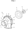
- FIG. 1 is a perspective view of a turbine housing assembly of the present invention.
- FIG. 2 is an exploded perspective view of the turbine housing assembly of the present invention.
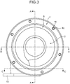
- FIG. 3 is a front view of the turbine housing assembly of the present invention.
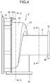
- FIG. 4 is a side view of the turbine housing assembly of the present invention.
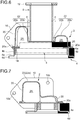
- FIGs. 5 to 9 are cross-sectional views taken along lines A-Ato E-E of FIGs. 3 and 4 .
- a turbine housing assembly 1 of the present invention is a turbine housing of a VG (variable geometry) turbocharger including a variable nozzle mechanism, for instance.
- the VG turbocharger includes a variable nozzle mechanism in a turbine housing and controls the amount of exhaust gas flow to be introduced by adjusting the opening degree of the nozzles in the variable nozzle mechanism according to the conditions of the engine. Then, the VG turbocharger controls the supply pressure to the optimum pressure by increasing or decreasing the rotation speed of a turbine wheel by the amount of exhaust gas flow.
- a turbine housing assembly 1 of the present invention is configured as illustrated in FIG. 1 by assembling a plurality of constituent members such as a scroll part 2, a connection part 4, an annular lid part 6, and an exhaust part 8 as illustrated in FIG. 2 . Then, as illustrated in FIG. 1 , a variable nozzle mechanism 3 and a turbine wheel 5 are inserted into the assembled turbine housing assembly 1 from the front side thereof. Further, a bearing housing (not illustrated) for housing a bearing that rotatably supports a rotation shaft of the turbine wheel 5 is connected to the front side of the assembled turbine housing assembly 1.
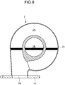
- the scroll part 2 has a bottomed cylindrical shape including a surrounding wall part 20 and a bottom face part 22. Further, as illustrated in FIG. 8 , an exhaust gas flow path 2A is formed into a spiral shape along the surrounding wall part 20 inside the scroll part 2 of a bottomed cylindrical shape, while an exhaust gas outlet 2B is disposed on the bottom face part 22, the exhaust gas outlet 2B having a through hole thereon at a position surrounded by the exhaust gas flow path 2A formed into a spiral shape.
- the bottom face of the exhaust gas flow path 2A of a spiral shape has a shape projecting toward the back face side of the bottom face part 22. Further, a cross-section of the flow path is formed so as to become shallow monotonically in a predetermined turning direction. Accordingly, the back face side of the bottom face part 22 is formed to have an uneven surface, including a recess portion 22b through which the exhaust gas outlet 2B is formed and a projecting portion 22a formed into a projecting shape that surrounds the recess portion 22b.
- a flange portion 20a is formed on an edge of the surrounding wall part 20, the flange portion 20a protruding outward in a direction substantially perpendicular with respect to the surrounding wall part 20. Also, a plurality of positioning portions 20b are formed on the flange portion 20a with equal intervals in the circumferential direction, the positioning portions 20b protruding outward from the flange portion 20a.
- an exhaust gas inlet 24 is formed on the upstream end of the exhaust gas flow path 2A.
- an engine-side flange portion 10 of a flat plate-like shape is connected by, for instance, welding.
- the engine-side flange portion 10 has bolt insertion holes 10b formed thereon so as to be fastened to an exhaust duct (not illustrated) by bolts. Accordingly, exhaust gas having a high temperature discharged from the engine flows through the exhaust duct to be introduced into the exhaust gas flow path 2A, passing through the exhaust gas inlet 24 from an opening 10a of the engine-side flange portion 10.
- the introduced exhaust gas is, after rotating the above described turbine wheel 5, discharged from the exhaust gas outlet 2B.
- the connection part 4 includes a flange portion 4a of an annular and flat plate-like shape and a protruding portion 4b of an annular shape protruding perpendicularly with respect to the flange portion 4a.
- the flange portion 4a has a plurality of bushing insertion holes 4c formed thereon with equal intervals in the circumferential direction of the flange portion 4a. It is configured such that a threaded bushing 16 that has a cylindrical shape and threads formed on its hole is inserted into each of the bushing insertion holes 4c.
- the threaded bushings 16 are used as bolt holes for fastening the above described bearing housing and the connection part 4 by bolts.
- the annular lid part 6 includes a flat plate-like part 6a of an annular shape and positioning portions 6b protruding outward from the flat plate-like part 6a.
- the positioning portions 6b are disposed on the positions corresponding to the positioning portions 20b of the scroll part 2 and the bushing insertion holes 4c of the connection part 4 described above with the same intervals as the above.
- the scroll part 2, the connection part 4, and the annular lid part 6 are each formed by processing a single piece of sheet metal. That is, each of the above is formed by plastic-deforming a flat plate-like piece of sheet metal into a predetermined shape by processes such as bending and pressing, or by partially cutting-off unnecessary portions by processes such as punching. Further, as a material of the scroll part 2, connection part 4, and annular lid part 6, for instance, a heat-resistant steel such as austenite stainless steel may be suitably used.
- the exhaust part 8 is formed into a tubular shape. Further, an end portion 8a of the exhaust part 8 is connected to the recess portion 22b at the back face side of the bottom face part 22 of the scroll part 2 described above by welding for instance, to be in communication with the exhaust gas outlet 2B. Meanwhile, to the other end portion 8b of the exhaust part 8, a muffler-side flange portion 12 including an annular and flat plate-like member is connected by, for instance, welding.
- exhaust gas that has flowed through the exhaust part 8 passes through the muffler-side exhaust duct to be discharged outside of the vehicle from a muffler.
- a gap "a" is formed between the projecting portion 22a and the outer circumferential face of the exhaust part 8 connected to the recess portion 22b of the scroll part 2.
- the gap "a" between the outer circumferential face of the exhaust part 8 and the projecting portion 22a means a distance which separates the outer circumferential face of the exhaust part 8 and the projecting portion 22a in a direction perpendicular to the outer surface of the exhaust part 8.
- the temperature of the exhaust gas flowing into the exhaust part 8 is lower than that of the exhaust gas flowing through the exhaust gas flow path 2A by approximately 100 degrees. Accordingly, with the exhaust part 8 and the scroll part 2 being connected so that the gap "a" is formed between the outer circumferential face of the exhaust part 8 and the projecting portion 22a, it becomes difficult for the exhaust gas having a high temperature and flowing through the exhaust gas flow path 2A to affect the exhaust part 8.
- a material of the exhaust part 8 in accordance with the temperature of the exhaust gas that passes through the exhaust part 8.
- it is possible to form the exhaust part 8 of a material having less heat resistance than that of the scroll part 2 specifically, a stainless material that contains less nickel and is less expensive).
- reinforcement ribs 25 are disposed on the inner circumferential side of the projecting portion 22a of the scroll part 2.
- the reinforcement ribs 25 are connected to the outer circumferential face of the exhaust part 8 by, for instance, welding.
- a plurality of (for instance, three) reinforcement ribs 25 are disposed with equal intervals in the circumferential direction.
- the reinforcement ribs 25 of the present embodiment are provided integrally with the projecting portion 22a of the scroll part 2.
- the present invention is not limited to this.
- the reinforcement ribs 25 may be provided integrally with the exhaust part 8 and connected to the inner circumferential side of the projecting portion 22a.
- the reinforcement ribs 25 may be provided separately from the scroll part 2 and the exhaust part 8, and connected to the inner circumferential side of the projecting portion 22a and the outer circumferential face of the exhaust part 8.
- a turbine housing is broken down into modules such as the scroll part 2 inside which the exhaust gas flow path 2A of a spiral shape is formed and the connection part 4 connectable to a bearing housing, and the scroll part 2 and the connection part 4 are each formed by processing a single piece of sheet metal. Further, the scroll part 2 and the connection part 4 are each welded to the annular lid part 6 that is orthogonal to the turbine axial direction line 7 so as to be connected to each other in the turbine axial direction via the annular lid part 6.
- the turbine housing assembly 1 of the present invention configured as described above, since a turbine housing is broken down into modules such as the scroll part 2 and the connection part 4, each of which being formed by processing a single piece of sheet metal, it is possible to reduce the heat capacity and weight of the turbine housing. Further, since they are each formed by processing a single piece of sheet metal, the manufacture of the scroll part 2 and the connection part 4 is facilitated.
- a turbine housing is broken down into modules such as the scroll part 2 inside which an exhaust gas flow path 2A of a spiral shape is formed and the connection part 4 connectable to a bearing housing, the scroll part 2 and the connection part 4 being connected to each other via the annular lid part 6, it is possible to configure the turbine housing assembly 1 of the present invention as an assembly of a plurality of standardized constituent modules. Thus, it is possible to facilitate the manufacture. Moreover, since the scroll part 2 and the connection part 4 are connected to each other by welding, the sealability is enhanced and thus the conventional outer shell is no longer required. As a result, it is possible to reduce the weight and heat capacity of the turbine housing.
- the turbine housing is broken down into modules such as the scroll part 2 and the connection part 4, which are connected to each other in the turbine axial direction via the annular lid part 6 that is orthogonal to the turbine axial direction line 7, it is possible to block the influence of the exhaust gas having a high temperature in the scroll part 2 by the annular lid part 6.
- the connection part 4 of a stainless material having lower heat resistance than that of the scroll part 2. That is, it is possible to form the connection part 4 of a less expensive stainless material containing less nickel than the scroll part 2.
- each constituent member such as the scroll part 2, the connection part 4, and the annular lid part 6 into a simple shape.
- it is possible to facilitate the manufacture of each constituent member.
- forming the annular lid part 6 by processing a single piece of sheet metal also contributes to reducing the weight and heat capacity of a turbine housing.
- the turbine housing assembly 1 of the present invention further includes the exhaust part 8 of a tubular shape having a separate body separate from the scroll part 2, and the exhaust part 8 is connected to the scroll part 2 in the turbine axial direction so that the exhaust part 8 is in communication with the exhaust gas outlet 2B.
- the constituent members such as the connection part 4, the annular lid part 6, the scroll part 2 and the exhaust part 8 are all connected in the turbine axial direction. As a result, assembling property of the turbine housing assembly 1 is enhanced.
- the turbine housing is broken down into modules such as the scroll part 2 and the exhaust part 8, the exhaust part 8 being brought into communication with the exhaust gas outlet 2B of the scroll part 2 in a state where the gap "a" is formed between the outer circumferential face of the exhaust part 8 and the projecting portion 22a of the scroll part 2, it becomes difficult for the exhaust gas having a high temperature and flowing through the exhaust gas flow path 2A of the scroll part 2 to affect the exhaust part 8.
- the exhaust part 8 of a material having lower heat resistance than that of the scroll part 2.
- the exhaust part 8 of a less expensive stainless material containing less nickel than the scroll part 2. As a result, it is possible to reduce the cost.
- the turbine housing assembly 1 of the present invention including a plurality of constituent members such as the scroll part 2, the connection part 4, the annular lid part 6 and the exhaust part 8 is manufactured as described below.
- the scroll part 2, the connection part 4, and the annular lid part 6 are each formed by processing a single piece of sheet metal (scroll part forming step, connection part forming step, and annular lid part forming step), and then the exhaust part 8, the engine-side flange portion 10, the muffler-side flange portion 12, etc are prepared.
- the annular lid part 6 is oriented so as to be orthogonal to the turbine axial direction line 7. Then the scroll part 2 is welded to one side, and the connection part 4 is welded to the other side of the annular lid part 6 (welding step).
- the flange portion 20a at the front side thereof is welded to the flat plate-like part 6a of the annular lid part 6.
- the edge of the protruding portion 4b is welded to the flat plate-like part 6a of the annular lid part 6.
- the scroll part 2 is oriented so as to be orthogonal to the turbine axial direction line 7 and the exhaust part 8 is oriented so that its longitudinal direction comes along with the turbine axial direction line 7. Then one end portion 8a of the exhaust part 8 and the recess portion 22b of the scroll part 2 are welded to each other for instance, thereby connecting the exhaust part 8 and the scroll part 2 in the turbine axial direction (connecting step).
- the engine-side flange portion 10 is connected by welding, for instance.
- the muffler-side flange portion 12 is connected by welding, for instance.
- the engine-side flange portion 10 and the muffler-side flange portion 12 may be connected to the scroll part 2 and the exhaust part 8 in advance.
- a ring member 14 of an annular shape is inserted to be fitted into the connection part 4 from the front side thereof.
- the ring member 14 is inserted to a position where it contacts the annular lid part 6.
- the variable nozzle mechanism 3 is inserted into the inner circumferential side of the ring member 14.
- the technique for: connecting the end portion 8a of the exhaust part 8 to the scroll part 2; connecting the positioning portions 6b on the other side of the annular lid part 6 to the end faces of the threaded bushings 16; connecting the exhaust gas inlet 24 of the scroll part 2 to the engine-side flange portion 10; and connecting the other end portion 8b of the exhaust part 8 to the muffler-side flange portion 12, is not limited to welding.
- the connection may be performed by fastening bolts, brazing, or the like.
- a turbine housing is broken down into modules such as the scroll part 2 inside which the exhaust gas flow path 2A of a spiral shape is formed and the connection part 4 connectable to a bearing housing, the scroll part 2 and the connection part 4 being connected to each other via the annular lid part 6, it is possible to manufacture the turbine housing assembly 1 only by connecting the scroll part 2 and the connection part 4 that have been separately manufactured. Thus, the manufacture is facilitated.
- each constituent member such as the scroll part 2, the connection part 4, and the annular lid part 6 into a simple shape. As a result, the manufacture of each constituent member is facilitated.
- the exhaust part 8 of a tubular shape having a separate body separate from the scroll part 2 is prepared and connected to the scroll part 2 in the turbine axial direction so that the exhaust part 8 communicates with the exhaust gas outlet 2B of the scroll part 2 (connection step).
- the constituent members such as the connection part 4, the annular lid part 6, the scroll part 2, and the exhaust part 8 are all connected in the turbine axial direction. As a result, assembling property of the turbine housing assembly 1 is improved.
- the present invention it is possible to provide a turbine housing assembly in which reduction of weight, cost-cutting, facilitation of manufacture, reduction of heat capacity are even more promoted compared to a conventional turbine housing made of sheet metal, and a manufacturing method of the turbine housing assembly.
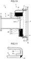
- FIG. 10 is a cross-sectional view of a turbine housing assembly of another embodiment of the present invention.
- the scroll part 2 of the present invention may include a fit-in portion 22c formed on the bottom face part 22, the fit-in portion 22c being formed by bending the bottom face part 22 around the exhaust gas outlet 2B toward the back face side so that the end portion 8a of the exhaust part 8 can be inserted and fitted therein.
- a fit-in portion 22c it is possible to insert and fit the end portion 8a of the exhaust part 8 into the fit-in portion 22c to connect the end portion 8a to the inner circumferential side of the fit-in portion 22c by a fillet weld 23 as illustrated in FIG. 11 , for instance.
- a fillet weld 23 as illustrated in FIG. 11
- the present invention can be suitably used as a turbine housing assembly for a turbocharger, preferably a turbine housing assembly for a VG turbocharger for a vehicle, and as a manufacturing method of the turbine housing assembly.
Landscapes
- Engineering & Computer Science (AREA)
- Mechanical Engineering (AREA)
- General Engineering & Computer Science (AREA)
- Supercharger (AREA)
Claims (9)
- Eine Turbinengehäuseanordnung (1), die eine Vielzahl von miteinander verbundenen Bestandteilen enthält, um ein Turbinengehäuse zu bilden, in das ein Turbinenrad (5) eingesetzt ist, das durch von einem Motor eingeführte Abgase gedreht wird, wobei die Turbinengehäuseanordnung (1) zumindest umfasst:
ein Scroll-Teil (2) von zylindrischer Form mit Boden, das einen umgebenden Wandteil (20) und einen Bodenflächenteil (22) aufweist, wobei das Scroll-Teil (2) Folgendes umfasst:einen Abgasströmungsweg (2A) mit einer Spiralform, der innerhalb der mit einem Boden versehenen zylindrischen Form ausgebildet und so konfiguriert ist, dass Abgas, das von einem Abgaseinlass eingeströmt ist, durch den Abgasströmungsweg strömt; undeinen Abgasauslass (2B) mit einem Durchgangsloch, das an dem Bodenflächenteil ausgebildet ist, wobei der Abgasauslass (2B) so konfiguriert ist, dass das Abgas, das durch den Abgasströmungsweg geströmt ist, aus dem Abgasauslass (2B) herausströmt; undein Verbindungsteil (4), das mit einem Lagergehäuse verbindbar ist, das ein Lager zur Lagerung einer Rotationswelle des Turbinenrads (5) aufnimmt,wobei das Scroll-Teil (2) und das Verbindungsteil (4) jeweils durch Bearbeitung eines einzigen Blechteils gebildet und jeweils mit einem ringförmigen Deckelteil (6) verschweißt sind, das orthogonal zu einer Turbinen-Axialrichtung (7) ist, so dass das Scroll-Teil (2) und das Verbindungsteil (4) in der Turbinen-Axialrichtung (7) über das ringförmige Deckelteil (6) miteinander verbunden sind, dadurch gekennzeichnet, dass der ringförmige Deckelteil (6) einen flachen, plattenförmigen Teil (6a) von ringförmiger Form und Positionierungsabschnitte (6b) aufweist, die von dem flachen, plattenförmigen Teil (6a) nach außen vorstehen, wobei die Positionierungsabschnitte (6b) an den Positionen angeordnet sind, die den Positionierungsabschnitten (20b) des Scroll-Teils (2) und den an dem Verbindungsteil (4) ausgebildeten Buchseneinsetzlöchern (4c) entsprechen,eine Stirnseite einer Gewindebuchse (16), die in jedes der Buchseneinsetzlöcher (4c) eingesetzt ist, mit dem Positionierungsabschnitt (6b) des ringförmigen Deckelteils (6) verbunden ist, undeine Seite des ringförmigen Deckelteils (6) ist mit dem Scroll-Teil (2) und die andere Seite des ringförmigen Deckelteils (6) mit dem Verbindungsteil (4) verschweißt. - Die Turbinengehäuseanordnung nach Anspruch 1, wobei das Verbindungsteil (4) aus einem Material hergestellt ist, das eine geringere Wärmebeständigkeitsfestigkeit als das Scroll-Teil (2) aufweist.
- Die Turbinengehäuseanordnung nach Anspruch 2, wobei das Verbindungsteil (4) aus einem Material hergestellt ist, das weniger Nickel als das Scroll-Teil (2) enthält.
- Die Turbinengehäuseanordnung nach einem der Ansprüche 1 bis 3, wobei der ringförmige Deckelteil (6) einen von dem Scroll-Teil (2) und dem Verbindungsteil (4) getrennten Körper aufweist.
- Die Turbinengehäuseanordnung nach Anspruch 4, wobei der ringförmige Deckelteil (6) durch Bearbeitung eines einzigen Blechstücks gebildet wird.
- Die Turbinengehäuseanordnung nach Anspruch 4 oder 5, die weiterhin ein röhrenförmiges Auslassteil (8) umfasst, das einen vom Scroll-Teil (2) getrennten separaten Körper aufweist, wobei das Auslassteil (8) mit dem Scroll-Teil (2) in der axialen Richtung (7) der Turbine verbunden ist, so dass das Auslassteil (8) mit dem Abgasauslass (2B) in Verbindung steht.
- Die Turbinengehäuseanordnung nach einem der Ansprüche 1 bis 6, ferner umfassend einen variablen Düsenmechanismus (3), der so konfiguriert ist, dass er die Strömung des zum Turbinenrad (5) strömenden Abgases einstellt, wobei der variable Düsenmechanismus (3) in das Scroll-Teil (2) und das Verbindungsteil (4) eingesetzt ist.
- Herstellungsverfahren für eine Turbinengehäuseanordnung (1), die eine Vielzahl von miteinander verbundenen Bestandteilen enthält, um ein Turbinengehäuse zu bilden, in das ein Turbinenrad (5), das durch von einem Motor eingeleitete Abgase gedreht wird, eingeführt wird, wobei das Herstellungsverfahren umfasst:
einen Scrollteil-Bildungsschritt zum Bilden eines Scroll-Teils (2) durch Verarbeitung eines einzigen Blechstücks, wobei das Scroll-Teil (2) aufweist:eine zylindrische Form mit Boden, die ein umgebendes Wandteil (20) und ein Bodenflächenteil (22) aufweist;einen Abgasströmungsweg (2A) mit einer Spiralform, der innerhalb der mit einem Boden versehenen zylindrischen Form ausgebildet ist, wobei der Abgasströmungsweg (2A) so konfiguriert ist, dass Abgas, das von einem Abgaseinlass eingeströmt ist, durch den Abgasströmungsweg strömt; undeinen Abgasauslass (2B) mit einem Durchgangsloch, das an dem Bodenflächenteil ausgebildet ist, wobei der Abgasauslass (2B) so konfiguriert ist, dass das Abgas, das durch den Abgasströmungsweg geströmt ist, aus dem Abgasauslass (2B) herausströmt;einen Verbindungsteil-Bildungsschritt zum Bilden eines Verbindungsteils (4) durch Verarbeiten eines einzelnen Blechstücks, wobei das Verbindungsteil (4) mit einem Lagergehäuse verbindbar ist, das ein Lager zum Tragen einer Drehwelle des Turbinenrads (5) aufnimmt;einen Herstellschritt zur Herstellung eines ringförmigen Deckelteils (6), mit einer flachen, plattenartigen Teils mit Ringform durch Bearbeiten eines einzelnen Blechstücks, dadurch gekennzeichnet, dass der ringförmige Deckelteil (6) einen flachen, plattenähnlichen Teil (6a) von ringförmiger Form und einen Positionierungsabschnitt (6b) aufweist, der von dem flachen, plattenähnlichen Teil (6a) nach außen vorsteht, wobei die Positionierungsabschnitte (6b) an den Positionen angeordnet sind, die den Positionierungsabschnitten (20b) des Scroll-Teils (2) und den am Verbindungsteil (4) ausgebildeten Buchseneinsetzlöchern (4c) entsprechen; undeinen Schweißschritt, bei dem der ringförmige Deckelteil (6) so angeordnet wird, dass er orthogonal zu einer Turbinenaxialrichtung (7) ist, bei dem der Scroll-Teil (2) an eine Seite des ringförmigen Deckelteils (6) geschweißt wird und bei dem der Verbindungsteil (4) an die andere Seite des ringförmigen Deckelteils (6) geschweißt wird, wobeieine Stirnseite einer Gewindebuchse (16), die in jedes der Buchseneinsetzlöcher (4c) eingesetzt wird, mit dem Positionierungsabschnitt (6b) des ringförmigen Deckelteils (6) verbunden ist. - Herstellungsverfahren für eine Turbinengehäuseanordnung nach Anspruch 8, das ferner einen Verbindungsschritt des Vorbereitens eines Auslassteils (8) mit einer röhrenförmigen Form, das einen separaten Körper getrennt von dem Scroll-Teil (2) umfasst, und des Verbindens des Auslassteils (8) mit dem Scroll-Teil (2) in der axialen Richtung (7) der Turbine umfasst, so dass das Auslassteil (8) in Verbindung mit dem Abgasauslass (2B) des Scroll-Teils (2) steht.
Applications Claiming Priority (2)
| Application Number | Priority Date | Filing Date | Title |
|---|---|---|---|
| JP2012068209A JP5984446B2 (ja) | 2012-03-23 | 2012-03-23 | タービンハウジングアセンブリおよびタービンハウジングアセンブリの製造方法 |
| PCT/JP2013/058389 WO2013141379A1 (ja) | 2012-03-23 | 2013-03-22 | タービンハウジングアセンブリおよびタービンハウジングアセンブリの製造方法 |
Publications (3)
| Publication Number | Publication Date |
|---|---|
| EP2829703A1 EP2829703A1 (de) | 2015-01-28 |
| EP2829703A4 EP2829703A4 (de) | 2016-04-13 |
| EP2829703B1 true EP2829703B1 (de) | 2020-04-22 |
Family
ID=49222827
Family Applications (1)
| Application Number | Title | Priority Date | Filing Date |
|---|---|---|---|
| EP13764441.5A Active EP2829703B1 (de) | 2012-03-23 | 2013-03-22 | Turbinengehäuseanordnung und herstellungsverfahren für eine turbinengehäuseanordnung |
Country Status (5)
| Country | Link |
|---|---|
| US (1) | US9835165B2 (de) |
| EP (1) | EP2829703B1 (de) |
| JP (1) | JP5984446B2 (de) |
| CN (1) | CN104379899B (de) |
| WO (1) | WO2013141379A1 (de) |
Families Citing this family (22)
| Publication number | Priority date | Publication date | Assignee | Title |
|---|---|---|---|---|
| USD751685S1 (en) * | 2013-08-06 | 2016-03-15 | Shinano Kenshi Co., Ltd. | Blower |
| USD740327S1 (en) * | 2013-11-19 | 2015-10-06 | Kawasaki Jukogyo Kabushiki Kaisha | Supercharger casing for internal combustion engines |
| WO2015097890A1 (ja) * | 2013-12-27 | 2015-07-02 | 三菱重工業株式会社 | タービンハウジング |
| CN104002276B (zh) * | 2014-05-07 | 2016-09-21 | 苏州通锦精密工业有限公司 | 螺孔自找正机构 |
| US10519806B2 (en) * | 2015-11-06 | 2019-12-31 | Calsonic Kansei Corporation | Turbine housing |
| USD785926S1 (en) * | 2016-01-05 | 2017-05-09 | Boostnatics, Llc | Keychain device |
| USD855786S1 (en) * | 2016-05-02 | 2019-08-06 | Boostnatics | Air freshener |
| USD857186S1 (en) * | 2016-05-02 | 2019-08-20 | Boostnatics | Air freshener |
| US10472988B2 (en) * | 2017-01-30 | 2019-11-12 | Garrett Transportation I Inc. | Sheet metal turbine housing and related turbocharger systems |
| US10436069B2 (en) * | 2017-01-30 | 2019-10-08 | Garrett Transportation I Inc. | Sheet metal turbine housing with biaxial volute configuration |
| US10494955B2 (en) | 2017-01-30 | 2019-12-03 | Garrett Transportation I Inc. | Sheet metal turbine housing with containment dampers |
| US10544703B2 (en) | 2017-01-30 | 2020-01-28 | Garrett Transportation I Inc. | Sheet metal turbine housing with cast core |
| US10690144B2 (en) * | 2017-06-27 | 2020-06-23 | Garrett Transportation I Inc. | Compressor housings and fabrication methods |
| WO2019044777A1 (ja) * | 2017-08-28 | 2019-03-07 | 株式会社豊田自動織機 | ターボチャージャ |
| DE112019006695T5 (de) * | 2019-02-25 | 2021-10-07 | Mitsubishi Heavy Industries Engine & Turbocharger, Ltd. | Turbinengehäuse und Turbolader |
| US11136997B2 (en) * | 2019-07-23 | 2021-10-05 | Ford Global Technologies, Llc | Methods and systems for a compressor housing |
| US11732729B2 (en) | 2021-01-26 | 2023-08-22 | Garrett Transportation I Inc | Sheet metal turbine housing |
| US11851202B1 (en) | 2022-06-23 | 2023-12-26 | Pratt & Whitney Canada Corp. | Aircraft engine, gas turbine intake therefore, and method of guiding exhaust gasses |
| US11891947B2 (en) | 2022-06-23 | 2024-02-06 | Pratt & Whitney Canada Corp. | Aircraft engine, gas turbine intake therefore, and method of guiding exhaust gasses |
| US11821361B1 (en) * | 2022-07-06 | 2023-11-21 | Pratt & Whitney Canada Corp. | Gas turbine intake for aircraft engine and method of inspection thereof |
| US12188364B2 (en) | 2022-07-06 | 2025-01-07 | Pratt & Whitney Canada Corp. | Damper segment for pressurized gas pipe of aircraft engine |
| CN117206891B (zh) * | 2023-11-09 | 2024-01-30 | 常州市皋翔汽车零部件有限公司 | 一种用于低压涡轮轴的定位装配机构 |
Family Cites Families (14)
| Publication number | Priority date | Publication date | Assignee | Title |
|---|---|---|---|---|
| JPS61132800A (ja) * | 1984-11-29 | 1986-06-20 | Mitsubishi Heavy Ind Ltd | 過給機用コンプレツサ−ハウジング及びその製造方法 |
| US4850797A (en) | 1988-01-21 | 1989-07-25 | Benson Steven R | Double chambered turbine housing and seal |
| DE10061846B4 (de) | 2000-12-12 | 2004-09-09 | Daimlerchrysler Ag | Abgasturbolader für eine Brennkraftmaschine |
| DE10218436C1 (de) * | 2002-04-25 | 2003-08-14 | Benteler Automobiltechnik Gmbh | Abgasturbine für einen Turbolader |
| GB0223756D0 (en) | 2002-10-14 | 2002-11-20 | Holset Engineering Co | Compressor |
| DE10325649B4 (de) * | 2003-06-06 | 2014-10-23 | Ihi Charging Systems International Gmbh | Abgasturbine für einen Abgasturbolader |
| DE10352960B4 (de) | 2003-11-13 | 2006-06-14 | Benteler Automobiltechnik Gmbh | Gehäuseanordnung für den Turbolader einer Brennkraftmaschine |
| DE102004039477B4 (de) * | 2004-08-14 | 2015-01-08 | Ihi Charging Systems International Gmbh | Turbinengehäuse für einen Abgasturbolader |
| JP4634319B2 (ja) | 2006-02-23 | 2011-02-16 | アイシン高丘株式会社 | タービンハウジング |
| JP4835330B2 (ja) * | 2006-08-31 | 2011-12-14 | トヨタ自動車株式会社 | タービンハウジング |
| WO2010052911A1 (ja) * | 2008-11-05 | 2010-05-14 | 株式会社Ihi | ターボチャージャ |
| JP5395574B2 (ja) | 2008-11-27 | 2014-01-22 | 株式会社東芝 | 蒸気機器 |
| US8372335B2 (en) | 2010-01-14 | 2013-02-12 | Honeywell International Inc. | Austenitic ductile cast iron |
| JP5769407B2 (ja) | 2010-02-01 | 2015-08-26 | 三菱重工業株式会社 | 板金タービンハウジング |
-
2012
- 2012-03-23 JP JP2012068209A patent/JP5984446B2/ja active Active
-
2013
- 2013-03-22 US US14/387,104 patent/US9835165B2/en active Active
- 2013-03-22 EP EP13764441.5A patent/EP2829703B1/de active Active
- 2013-03-22 WO PCT/JP2013/058389 patent/WO2013141379A1/ja not_active Ceased
- 2013-03-22 CN CN201380015197.XA patent/CN104379899B/zh active Active
Non-Patent Citations (1)
| Title |
|---|
| None * |
Also Published As
| Publication number | Publication date |
|---|---|
| EP2829703A4 (de) | 2016-04-13 |
| US9835165B2 (en) | 2017-12-05 |
| CN104379899A (zh) | 2015-02-25 |
| US20150086347A1 (en) | 2015-03-26 |
| CN104379899B (zh) | 2017-03-15 |
| JP2013199863A (ja) | 2013-10-03 |
| WO2013141379A1 (ja) | 2013-09-26 |
| EP2829703A1 (de) | 2015-01-28 |
| JP5984446B2 (ja) | 2016-09-06 |
Similar Documents
| Publication | Publication Date | Title |
|---|---|---|
| EP2829703B1 (de) | Turbinengehäuseanordnung und herstellungsverfahren für eine turbinengehäuseanordnung | |
| EP2829702B1 (de) | Turbinengehäuseanordnung | |
| US7862295B2 (en) | Device for guiding a stream of air entering a combustion chamber of a turbomachine | |
| US20110120124A1 (en) | Exhaust gas turbocharger | |
| US10041389B2 (en) | Valve housing and valve | |
| US9194258B2 (en) | Gas turbine engine case bosses | |
| EP2334910B1 (de) | Gefertigtes turbinengehäuse | |
| EP2531701B1 (de) | Turbolader und gehäuse für ein turboladerrad | |
| US20160003259A1 (en) | Turbocharger | |
| EP2524128B1 (de) | Radgehäuse für einen turbolader | |
| US20140196978A1 (en) | Silencer and method for manufacturing the same | |
| US10233828B2 (en) | Variable nozzle unit and variable geometry system turbocharger | |
| US11484934B2 (en) | Manufacturing method of casing | |
| EP3473354A1 (de) | Hohles produkt und verfahren zur herstellung des produkts | |
| JP6320281B2 (ja) | タービンハウジング | |
| US10532500B2 (en) | Hollow product and method of making the product |
Legal Events
| Date | Code | Title | Description |
|---|---|---|---|
| PUAI | Public reference made under article 153(3) epc to a published international application that has entered the european phase |
Free format text: ORIGINAL CODE: 0009012 |
|
| 17P | Request for examination filed |
Effective date: 20140922 |
|
| AK | Designated contracting states |
Kind code of ref document: A1 Designated state(s): AL AT BE BG CH CY CZ DE DK EE ES FI FR GB GR HR HU IE IS IT LI LT LU LV MC MK MT NL NO PL PT RO RS SE SI SK SM TR |
|
| AX | Request for extension of the european patent |
Extension state: BA ME |
|
| DAX | Request for extension of the european patent (deleted) | ||
| RA4 | Supplementary search report drawn up and despatched (corrected) |
Effective date: 20160314 |
|
| RIC1 | Information provided on ipc code assigned before grant |
Ipc: F02B 39/00 20060101AFI20160308BHEP Ipc: F04D 17/10 20060101ALI20160308BHEP Ipc: F01D 9/02 20060101ALI20160308BHEP |
|
| STAA | Information on the status of an ep patent application or granted ep patent |
Free format text: STATUS: EXAMINATION IS IN PROGRESS |
|
| 17Q | First examination report despatched |
Effective date: 20180718 |
|
| RAP1 | Party data changed (applicant data changed or rights of an application transferred) |
Owner name: MITSUBISHI HEAVY INDUSTRIES ENGINE & TURBOCHARGER, |
|
| GRAP | Despatch of communication of intention to grant a patent |
Free format text: ORIGINAL CODE: EPIDOSNIGR1 |
|
| STAA | Information on the status of an ep patent application or granted ep patent |
Free format text: STATUS: GRANT OF PATENT IS INTENDED |
|
| INTG | Intention to grant announced |
Effective date: 20191108 |
|
| RIN1 | Information on inventor provided before grant (corrected) |
Inventor name: ARIMIZU, HIROYUKI Inventor name: KRAMER, KOEN Inventor name: JINNAI, YASUAKI |
|
| GRAS | Grant fee paid |
Free format text: ORIGINAL CODE: EPIDOSNIGR3 |
|
| GRAA | (expected) grant |
Free format text: ORIGINAL CODE: 0009210 |
|
| STAA | Information on the status of an ep patent application or granted ep patent |
Free format text: STATUS: THE PATENT HAS BEEN GRANTED |
|
| AK | Designated contracting states |
Kind code of ref document: B1 Designated state(s): AL AT BE BG CH CY CZ DE DK EE ES FI FR GB GR HR HU IE IS IT LI LT LU LV MC MK MT NL NO PL PT RO RS SE SI SK SM TR |
|
| REG | Reference to a national code |
Ref country code: GB Ref legal event code: FG4D |
|
| REG | Reference to a national code |
Ref country code: CH Ref legal event code: EP |
|
| REG | Reference to a national code |
Ref country code: IE Ref legal event code: FG4D |
|
| REG | Reference to a national code |
Ref country code: DE Ref legal event code: R096 Ref document number: 602013068180 Country of ref document: DE |
|
| REG | Reference to a national code |
Ref country code: AT Ref legal event code: REF Ref document number: 1260375 Country of ref document: AT Kind code of ref document: T Effective date: 20200515 |
|
| REG | Reference to a national code |
Ref country code: LT Ref legal event code: MG4D |
|
| REG | Reference to a national code |
Ref country code: NL Ref legal event code: MP Effective date: 20200422 |
|
| PG25 | Lapsed in a contracting state [announced via postgrant information from national office to epo] |
Ref country code: NO Free format text: LAPSE BECAUSE OF FAILURE TO SUBMIT A TRANSLATION OF THE DESCRIPTION OR TO PAY THE FEE WITHIN THE PRESCRIBED TIME-LIMIT Effective date: 20200722 Ref country code: IS Free format text: LAPSE BECAUSE OF FAILURE TO SUBMIT A TRANSLATION OF THE DESCRIPTION OR TO PAY THE FEE WITHIN THE PRESCRIBED TIME-LIMIT Effective date: 20200822 Ref country code: GR Free format text: LAPSE BECAUSE OF FAILURE TO SUBMIT A TRANSLATION OF THE DESCRIPTION OR TO PAY THE FEE WITHIN THE PRESCRIBED TIME-LIMIT Effective date: 20200723 Ref country code: PT Free format text: LAPSE BECAUSE OF FAILURE TO SUBMIT A TRANSLATION OF THE DESCRIPTION OR TO PAY THE FEE WITHIN THE PRESCRIBED TIME-LIMIT Effective date: 20200824 Ref country code: NL Free format text: LAPSE BECAUSE OF FAILURE TO SUBMIT A TRANSLATION OF THE DESCRIPTION OR TO PAY THE FEE WITHIN THE PRESCRIBED TIME-LIMIT Effective date: 20200422 Ref country code: LT Free format text: LAPSE BECAUSE OF FAILURE TO SUBMIT A TRANSLATION OF THE DESCRIPTION OR TO PAY THE FEE WITHIN THE PRESCRIBED TIME-LIMIT Effective date: 20200422 Ref country code: SE Free format text: LAPSE BECAUSE OF FAILURE TO SUBMIT A TRANSLATION OF THE DESCRIPTION OR TO PAY THE FEE WITHIN THE PRESCRIBED TIME-LIMIT Effective date: 20200422 Ref country code: FI Free format text: LAPSE BECAUSE OF FAILURE TO SUBMIT A TRANSLATION OF THE DESCRIPTION OR TO PAY THE FEE WITHIN THE PRESCRIBED TIME-LIMIT Effective date: 20200422 |
|
| REG | Reference to a national code |
Ref country code: AT Ref legal event code: MK05 Ref document number: 1260375 Country of ref document: AT Kind code of ref document: T Effective date: 20200422 |
|
| PG25 | Lapsed in a contracting state [announced via postgrant information from national office to epo] |
Ref country code: HR Free format text: LAPSE BECAUSE OF FAILURE TO SUBMIT A TRANSLATION OF THE DESCRIPTION OR TO PAY THE FEE WITHIN THE PRESCRIBED TIME-LIMIT Effective date: 20200422 Ref country code: LV Free format text: LAPSE BECAUSE OF FAILURE TO SUBMIT A TRANSLATION OF THE DESCRIPTION OR TO PAY THE FEE WITHIN THE PRESCRIBED TIME-LIMIT Effective date: 20200422 Ref country code: BG Free format text: LAPSE BECAUSE OF FAILURE TO SUBMIT A TRANSLATION OF THE DESCRIPTION OR TO PAY THE FEE WITHIN THE PRESCRIBED TIME-LIMIT Effective date: 20200722 Ref country code: RS Free format text: LAPSE BECAUSE OF FAILURE TO SUBMIT A TRANSLATION OF THE DESCRIPTION OR TO PAY THE FEE WITHIN THE PRESCRIBED TIME-LIMIT Effective date: 20200422 |
|
| PG25 | Lapsed in a contracting state [announced via postgrant information from national office to epo] |
Ref country code: AL Free format text: LAPSE BECAUSE OF FAILURE TO SUBMIT A TRANSLATION OF THE DESCRIPTION OR TO PAY THE FEE WITHIN THE PRESCRIBED TIME-LIMIT Effective date: 20200422 |
|
| REG | Reference to a national code |
Ref country code: DE Ref legal event code: R097 Ref document number: 602013068180 Country of ref document: DE |
|
| PG25 | Lapsed in a contracting state [announced via postgrant information from national office to epo] |
Ref country code: ES Free format text: LAPSE BECAUSE OF FAILURE TO SUBMIT A TRANSLATION OF THE DESCRIPTION OR TO PAY THE FEE WITHIN THE PRESCRIBED TIME-LIMIT Effective date: 20200422 Ref country code: CZ Free format text: LAPSE BECAUSE OF FAILURE TO SUBMIT A TRANSLATION OF THE DESCRIPTION OR TO PAY THE FEE WITHIN THE PRESCRIBED TIME-LIMIT Effective date: 20200422 Ref country code: RO Free format text: LAPSE BECAUSE OF FAILURE TO SUBMIT A TRANSLATION OF THE DESCRIPTION OR TO PAY THE FEE WITHIN THE PRESCRIBED TIME-LIMIT Effective date: 20200422 Ref country code: SM Free format text: LAPSE BECAUSE OF FAILURE TO SUBMIT A TRANSLATION OF THE DESCRIPTION OR TO PAY THE FEE WITHIN THE PRESCRIBED TIME-LIMIT Effective date: 20200422 Ref country code: AT Free format text: LAPSE BECAUSE OF FAILURE TO SUBMIT A TRANSLATION OF THE DESCRIPTION OR TO PAY THE FEE WITHIN THE PRESCRIBED TIME-LIMIT Effective date: 20200422 Ref country code: EE Free format text: LAPSE BECAUSE OF FAILURE TO SUBMIT A TRANSLATION OF THE DESCRIPTION OR TO PAY THE FEE WITHIN THE PRESCRIBED TIME-LIMIT Effective date: 20200422 Ref country code: IT Free format text: LAPSE BECAUSE OF FAILURE TO SUBMIT A TRANSLATION OF THE DESCRIPTION OR TO PAY THE FEE WITHIN THE PRESCRIBED TIME-LIMIT Effective date: 20200422 Ref country code: DK Free format text: LAPSE BECAUSE OF FAILURE TO SUBMIT A TRANSLATION OF THE DESCRIPTION OR TO PAY THE FEE WITHIN THE PRESCRIBED TIME-LIMIT Effective date: 20200422 |
|
| PG25 | Lapsed in a contracting state [announced via postgrant information from national office to epo] |
Ref country code: SK Free format text: LAPSE BECAUSE OF FAILURE TO SUBMIT A TRANSLATION OF THE DESCRIPTION OR TO PAY THE FEE WITHIN THE PRESCRIBED TIME-LIMIT Effective date: 20200422 Ref country code: PL Free format text: LAPSE BECAUSE OF FAILURE TO SUBMIT A TRANSLATION OF THE DESCRIPTION OR TO PAY THE FEE WITHIN THE PRESCRIBED TIME-LIMIT Effective date: 20200422 |
|
| PLBE | No opposition filed within time limit |
Free format text: ORIGINAL CODE: 0009261 |
|
| STAA | Information on the status of an ep patent application or granted ep patent |
Free format text: STATUS: NO OPPOSITION FILED WITHIN TIME LIMIT |
|
| 26N | No opposition filed |
Effective date: 20210125 |
|
| PG25 | Lapsed in a contracting state [announced via postgrant information from national office to epo] |
Ref country code: SI Free format text: LAPSE BECAUSE OF FAILURE TO SUBMIT A TRANSLATION OF THE DESCRIPTION OR TO PAY THE FEE WITHIN THE PRESCRIBED TIME-LIMIT Effective date: 20200422 |
|
| PG25 | Lapsed in a contracting state [announced via postgrant information from national office to epo] |
Ref country code: MC Free format text: LAPSE BECAUSE OF FAILURE TO SUBMIT A TRANSLATION OF THE DESCRIPTION OR TO PAY THE FEE WITHIN THE PRESCRIBED TIME-LIMIT Effective date: 20200422 |
|
| REG | Reference to a national code |
Ref country code: CH Ref legal event code: PL |
|
| GBPC | Gb: european patent ceased through non-payment of renewal fee |
Effective date: 20210322 |
|
| REG | Reference to a national code |
Ref country code: BE Ref legal event code: MM Effective date: 20210331 |
|
| PG25 | Lapsed in a contracting state [announced via postgrant information from national office to epo] |
Ref country code: GB Free format text: LAPSE BECAUSE OF NON-PAYMENT OF DUE FEES Effective date: 20210322 Ref country code: FR Free format text: LAPSE BECAUSE OF NON-PAYMENT OF DUE FEES Effective date: 20210331 Ref country code: IE Free format text: LAPSE BECAUSE OF NON-PAYMENT OF DUE FEES Effective date: 20210322 Ref country code: LU Free format text: LAPSE BECAUSE OF NON-PAYMENT OF DUE FEES Effective date: 20210322 Ref country code: LI Free format text: LAPSE BECAUSE OF NON-PAYMENT OF DUE FEES Effective date: 20210331 Ref country code: CH Free format text: LAPSE BECAUSE OF NON-PAYMENT OF DUE FEES Effective date: 20210331 |
|
| PG25 | Lapsed in a contracting state [announced via postgrant information from national office to epo] |
Ref country code: BE Free format text: LAPSE BECAUSE OF NON-PAYMENT OF DUE FEES Effective date: 20210331 |
|
| PG25 | Lapsed in a contracting state [announced via postgrant information from national office to epo] |
Ref country code: HU Free format text: LAPSE BECAUSE OF FAILURE TO SUBMIT A TRANSLATION OF THE DESCRIPTION OR TO PAY THE FEE WITHIN THE PRESCRIBED TIME-LIMIT; INVALID AB INITIO Effective date: 20130322 |
|
| PG25 | Lapsed in a contracting state [announced via postgrant information from national office to epo] |
Ref country code: CY Free format text: LAPSE BECAUSE OF FAILURE TO SUBMIT A TRANSLATION OF THE DESCRIPTION OR TO PAY THE FEE WITHIN THE PRESCRIBED TIME-LIMIT Effective date: 20200422 |
|
| PG25 | Lapsed in a contracting state [announced via postgrant information from national office to epo] |
Ref country code: MK Free format text: LAPSE BECAUSE OF FAILURE TO SUBMIT A TRANSLATION OF THE DESCRIPTION OR TO PAY THE FEE WITHIN THE PRESCRIBED TIME-LIMIT Effective date: 20200422 |
|
| PG25 | Lapsed in a contracting state [announced via postgrant information from national office to epo] |
Ref country code: MT Free format text: LAPSE BECAUSE OF FAILURE TO SUBMIT A TRANSLATION OF THE DESCRIPTION OR TO PAY THE FEE WITHIN THE PRESCRIBED TIME-LIMIT Effective date: 20200422 |
|
| PGFP | Annual fee paid to national office [announced via postgrant information from national office to epo] |
Ref country code: DE Payment date: 20250128 Year of fee payment: 13 |
|
| PG25 | Lapsed in a contracting state [announced via postgrant information from national office to epo] |
Ref country code: TR Free format text: LAPSE BECAUSE OF FAILURE TO SUBMIT A TRANSLATION OF THE DESCRIPTION OR TO PAY THE FEE WITHIN THE PRESCRIBED TIME-LIMIT Effective date: 20200422 |