EP2531701B1 - Turbolader und gehäuse für ein turboladerrad - Google Patents
Turbolader und gehäuse für ein turboladerrad Download PDFInfo
- Publication number
- EP2531701B1 EP2531701B1 EP11712001.4A EP11712001A EP2531701B1 EP 2531701 B1 EP2531701 B1 EP 2531701B1 EP 11712001 A EP11712001 A EP 11712001A EP 2531701 B1 EP2531701 B1 EP 2531701B1
- Authority
- EP
- European Patent Office
- Prior art keywords
- shell body
- wheel
- turbocharger
- reinforcement
- connection portion
- Prior art date
- Legal status (The legal status is an assumption and is not a legal conclusion. Google has not performed a legal analysis and makes no representation as to the accuracy of the status listed.)
- Not-in-force
Links
- 230000002787 reinforcement Effects 0.000 claims description 58
- 230000002093 peripheral effect Effects 0.000 claims description 38
- 239000002184 metal Substances 0.000 claims description 24
- 229910052751 metal Inorganic materials 0.000 claims description 24
- 230000004308 accommodation Effects 0.000 claims description 11
- 238000004891 communication Methods 0.000 claims description 10
- 239000012634 fragment Substances 0.000 description 27
- 238000005219 brazing Methods 0.000 description 12
- 238000005304 joining Methods 0.000 description 10
- 238000000034 method Methods 0.000 description 8
- 239000000463 material Substances 0.000 description 7
- 238000004519 manufacturing process Methods 0.000 description 6
- 238000003466 welding Methods 0.000 description 6
- 238000010276 construction Methods 0.000 description 5
- 238000004080 punching Methods 0.000 description 4
- 229910000679 solder Inorganic materials 0.000 description 4
- 238000011144 upstream manufacturing Methods 0.000 description 4
- 230000004048 modification Effects 0.000 description 3
- 238000012986 modification Methods 0.000 description 3
- 230000000694 effects Effects 0.000 description 2
- 239000000155 melt Substances 0.000 description 2
- 238000002485 combustion reaction Methods 0.000 description 1
- 230000003247 decreasing effect Effects 0.000 description 1
- 150000002739 metals Chemical class 0.000 description 1
- 238000000465 moulding Methods 0.000 description 1
Images


Classifications
-
- F—MECHANICAL ENGINEERING; LIGHTING; HEATING; WEAPONS; BLASTING
- F01—MACHINES OR ENGINES IN GENERAL; ENGINE PLANTS IN GENERAL; STEAM ENGINES
- F01D—NON-POSITIVE DISPLACEMENT MACHINES OR ENGINES, e.g. STEAM TURBINES
- F01D9/00—Stators
- F01D9/02—Nozzles; Nozzle boxes; Stator blades; Guide conduits, e.g. individual nozzles
- F01D9/026—Scrolls for radial machines or engines
-
- F—MECHANICAL ENGINEERING; LIGHTING; HEATING; WEAPONS; BLASTING
- F01—MACHINES OR ENGINES IN GENERAL; ENGINE PLANTS IN GENERAL; STEAM ENGINES
- F01D—NON-POSITIVE DISPLACEMENT MACHINES OR ENGINES, e.g. STEAM TURBINES
- F01D21/00—Shutting-down of machines or engines, e.g. in emergency; Regulating, controlling, or safety means not otherwise provided for
- F01D21/04—Shutting-down of machines or engines, e.g. in emergency; Regulating, controlling, or safety means not otherwise provided for responsive to undesired position of rotor relative to stator or to breaking-off of a part of the rotor, e.g. indicating such position
- F01D21/045—Shutting-down of machines or engines, e.g. in emergency; Regulating, controlling, or safety means not otherwise provided for responsive to undesired position of rotor relative to stator or to breaking-off of a part of the rotor, e.g. indicating such position special arrangements in stators or in rotors dealing with breaking-off of part of rotor
-
- F—MECHANICAL ENGINEERING; LIGHTING; HEATING; WEAPONS; BLASTING
- F05—INDEXING SCHEMES RELATING TO ENGINES OR PUMPS IN VARIOUS SUBCLASSES OF CLASSES F01-F04
- F05D—INDEXING SCHEME FOR ASPECTS RELATING TO NON-POSITIVE-DISPLACEMENT MACHINES OR ENGINES, GAS-TURBINES OR JET-PROPULSION PLANTS
- F05D2220/00—Application
- F05D2220/40—Application in turbochargers
Definitions
- the invention relates to a turbocharger wheel housing that includes a shell body having a scroll portion and a base body having an accommodation portion in which a wheel is accommodated, with a gas passage formed between the shell body and the base body.
- turbocharger wheel housing As a turbocharger wheel housing, there is known a turbine housing disclosed in Japanese Patent Application Publication No. 2008-106667 ( JP-A-2008-106667 ). According to a sheet metal turbine housing such as this turbine housing, the thicknesses of respective wall portions can be made small in comparison with a cast turbine housing, so a reduction in weight and a reduction in thermal capacity can be achieved.
- the following problem arises due to a small thickness of a shell body. That is, should part of a wheel separate from a main body as a fragment during rotation thereof and hit the shell body, a region hit by the fragment is greatly deformed as a result of the small thickness of the shell body. It should be noted that a similar problem may be caused not only in a sheet metal housing but also in any housing with a shell body whose lateral wall portion includes a thin-walled portion.
- the invention provides a turbocharger and a wheel housing thereof that can restrain a shell body from being greatly deformed.
- a first aspect of the invention relates to a turbocharger wheel housing as defined in appended claim 1.
- the reinforcement portion is superposed on the peripheral wall of the scroll portion. Therefore, the amount of deformation of the second shell body can be made small when the fragment of the wheel hits the peripheral wall of the scroll portion.
- the reinforcement portion be structured not to include the slit portion. In the case of this structure, however, the operation of superposing the reinforcement portion on the peripheral wall of the scroll portion is troublesome in manufacturing the shell body.
- the slit portion is provided through the reinforcement portion. Therefore, the operability in superposing the reinforcement portion on the inner peripheral face or the outer peripheral face of the peripheral wall of the scroll portion can be made good.
- the pillar portion is so provided as to intersect with that tangential line of the wheel which passes the slit portion, the wheel moving from the main body of the wheel toward the slit portion. Therefore, when separating from the main body of the wheel, the fragment of the wheel hits the pillar portion located between the wheel and the slit portion, and hence is unlikely to hit the slit portion. Thus, that region of the second shell body which corresponds to the slit portion can be restrained from being greatly deformed.
- the pillar portion is provided on the traveling path of the fragment of the wheel moving from the main body of the wheel toward the slit portion. Therefore, when separating from the main body of the wheel, the fragment of the wheel hits the pillar portion located between the wheel and the slit portion, and hence is unlikely to hit the slit portion. Thus, that region of the second shell body which corresponds to the slit portion can be restrained from being greatly deformed.
- the pillar portion is so provided as to prevent the fragment of the wheel, which moves from the main body of the wheel toward the slit portion, from hitting the thin-walled portion. Therefore, when separating from the main body of the wheel, the fragment of the wheel hits the pillar portion located between the wheel and the slit portion, and hence is unlikely to hit the slit portion. Thus, that region of the second shell body which corresponds to the slit portion can be restrained from being greatly deformed.
- the first shell body and the second shell body may be provided as sheet metal shell bodies.
- the first shell body and the second shell body are provided as sheet metal shell bodies. Therefore, the wheel housing can be reduced in weight and thermal capacity. Further, due to the first shell body and the second shell body that are provided as sheet metal shell bodies, the peripheral wall is lower in strength in comparison with cast shell bodies. However, the peripheral wall is reinforced by the reinforcement portion, and hence can be restrained from being deformed.
- the shell body may include a connection portion that connects the scroll portion with an exhaust pipe or an intake pipe
- the first shell body may include a first divisional connection portion as part of the connection portion
- the second shell body may include a second divisional connection portion that forms part of the connection portion
- the connection portion may be composed of the first divisional connection portion and the second divisional connection portion that are combined with each other.
- the sheet metal shell body be structured with its connection portion undivided.
- the connection portion is composed of the first divisional connection portion and the second divisional connection portion that are combined with each other. Therefore, the process of punching out part of the sheet metal to form the connection portion is not required. Accordingly, the yield ratio of a material can be enhanced.
- the first shell body may be formed of a metal plate having an oblong flat plate portion and a protrusion portion that protrudes from a long side of the flat plate portion
- the reinforcement portion may be formed by working the flat plate portion into a cylindrical shape
- the first divisional connection portion may be obtained by working the protrusion portion into a circular shape.
- the first shell body be structured by forming the reinforcement portion and the first divisional connection portion separately from each other and joining them to each other through a joining operation such as welding or the like. In this case, however, the aforementioned joining operation is required in manufacturing the first shell body.
- the first shell body is formed of the single metal plate having the oblong flat plate portion and the protrusion portion protruding from the long side of this flat plate portion. Therefore, the first shell body can be manufactured without having to include a joining operation such as welding or the like.
- the base body may include a flange portion which protrudes radially outward beyond the accommodation portion
- the wheel housing may be formed by fitting one of the reinforcement portion of the first shell body and the scroll portion of the second shell body to an outer periphery of the flange portion of the base body and fitting the other of the reinforcement portion and the scroll portion to an inner periphery of the one of the reinforcement portion and the scroll portion that is fitted to the outer periphery of the flange.
- the reinforcement portion of the first shell body is fitted to the outer periphery of the flange portion of the base body, and the scroll portion of the second shell body is fitted to the inner periphery of the reinforcement portion.
- the scroll portion of the second shell body is fitted to the outer periphery of the flange portion of the base body, and the reinforcement portion of the first shell body is fitted to the inner periphery of the scroll portion of the second shell body.
- the aforementioned respective structural bodies are fitted to each other to remain combined with each other. Accordingly, a jig for combining the aforementioned respective structural bodies with each other can be dispensed with or simplified in construction.
- the pillar portion may be longer in a circumferential direction than the slit portion.
- a turbocharger turbine housing may be constructed in the same manner as the aforementioned wheel housing.
- the amount of deformation of the second shell body of the turbine housing can be made small, and the operability in superposing the reinforcement portion on the inner peripheral face or the outer peripheral face of the peripheral wall of the scroll portion can be made good.
- a turbocharger compressor housing may be constructed in the same manner as the aforementioned wheel housing.
- the amount of deformation of the second shell body of the compressor housing can be made small, and the operability in superposing the reinforcement portion on the inner peripheral face or the outer peripheral face of the peripheral wall of the scroll portion can be made good.
- a turbocharger may include the aforementioned wheel housing.
- FIGS. 1 to 7 The first embodiment of the invention will be described with reference to FIGS. 1 to 7 . It should be noted that this embodiment of the invention shows an example in which the invention is embodied as a turbocharger turbine housing for an internal combustion engine.
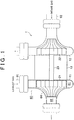
- a turbocharger 1 is provided with a turbine wheel 21 that rotates with the aid of the energy of exhaust gas, a compressor wheel 22 that compresses intake air as the wheel 21 rotates, a rotor shaft 23 that connects these wheels to each other, a turbine housing 11 that accommodates the turbine wheel 21, a compressor housing 12 that accommodates the compressor wheel 22, and a center housing 13 that accommodates the rotor shaft 23.
- An exhaust pipe 91 and an intake pipe 92 are connected to the turbine housing 11 and the compressor housing 12 respectively.
- the turbine wheel 21 and the compressor wheel 22 are connected to the rotor shaft 23 respectively. Therefore, these three elements rotate integrally. Further, the turbine housing 11 and the compressor housing 12 are connected to the center housing 13.
- a wheel chamber 64 in which the turbine wheel 21 is accommodated, and an exhaust passage 80 for causing an exhaust gas from an exhaust pipe 91 upstream of the turbine housing 11 to flow to the exhaust pipe 91 downstream of the turbine housing 11 are formed.
- the exhaust passage 80 is formed of the wheel chamber 64 in which the turbine wheel 21 is accommodated, and a scroll passage 81 for supplying the exhaust gas from the upstream exhaust pipe 91 to the wheel chamber 64, and an outlet passage for delivering the exhaust gas from the turbine wheel 21 to the downstream exhaust pipe 91.
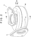
- the turbine housing 11 is configured to include a shell body 30 and a base body 60 that are combined with each other to form the exhaust passage 80, an inlet flange 71 connected to the exhaust pipe 91 upstream of the turbine housing 11 via a connection portion 31, and an outlet flange 72 to which the exhaust pipe 91 downstream of the turbine housing 11 is connected.
- the shell body 30 is composed of a first shell body 40 and a second shell body 50.
- the first shell body 40 and the second shell body 50 are obtained by press-molding sheet metals.
- the base body 60, the inlet flange 71, and the outlet flange 72 are cast.
- the second shell body 50 is configured to include a disk-like scroll portion 51, and a second divisional connection portion 54 constituting part of the connection portion 31.
- the scroll portion 51 is provided with a lateral wall portion 53 extending in a circumferential direction, and a top wall portion 52 extending in a radial direction.
- the first shell body 40 is configured to include a first divisional connection portion 41 constituting part of the connection portion 31, and a cylindrical reinforcement portion 42 elongated from the connection portion 41 in the circumferential direction to extend along an outer periphery of the lateral wall portion 53 of the second shell body 50.
- a slit portion 43 that is partially discontinuous in the circumferential direction is formed through the reinforcement portion 42. That is, the reinforcement portion 42 is constructed as a cylindrical element having a region that is discontinuous in the circumferential direction.
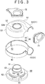
- the base body 60 is provided with a circular flange portion 62 for connecting the center housing 13 (see FIG. 1 ) and the turbine housing 11 to each other, a cylinder portion 61 to which a joint portion 52A of the second shell body 50 and the outlet flange 72 are fitted, and an accommodation portion 63 in which the turbine wheel 21 is accommodated.
- the accommodation portion 63 is provided in such a manner as to connect the cylinder portion 61 and the flange portion 62 to each other.
- the accommodation portion 63 is provided with communication portions 66 through which the scroll passage 81 and the wheel chamber 64 communicate with each other.
- Each of pillar portions 65 is provided between corresponding adjacent ones of the communication portions 66 in such a manner as to connect the flange portion 62 and the cylinder portion 61 to each other.
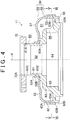
- FIG. 4 shows a cross-sectional structure of the turbine housing 11 along a line IV-IV of FIG. 2 . Further, alternate long and short dash lines P in FIG. 4 indicate centerlines of the turbine housing 11 and the turbine wheel 21.
- the outlet flange 72 is fitted to the outside of a tip end portion 61C of the cylinder portion 61 of the base body 60.
- An outer peripheral face 61A of the tip end portion 61C and an inner peripheral face 72A of the outlet flange 72 are joined to each other through brazing.
- a joint portion 52A of the second shell body 50 is fitted to the outside of a base end portion 61B of the cylinder portion 61 of the base body 60.
- An outer peripheral face 61A of the base end portion 61B and an inner peripheral face 52B of the joint portion 52A are joined to each other through brazing.
- the inner peripheral face 52B of the top wall portion 52 of the second shell body 50 is butted against a top face 63A of the accommodation portion 63 of the base body 60 in the vicinity of the cylinder portion 61.
- the top face 63A in the vicinity of the cylinder portion 61 and the inner peripheral face 52B of the top wall portion 52 are in contact with each other with no gap formed therebetween.
- a lower end face 53B of the lateral wall portion 53 of the second shell body 50 is butted against a top face 62A of the flange portion 62 of the base body 60.
- the top face 62A of the flange portion 62 and the lower end face 53B of the lateral wall portion 53 are joined to each other through brazing.
- a lower end portion 42B of the reinforcement portion 42 of the first shell body 40 is fitted to the outside of the flange portion 62 of the base body 60 and the outside of the lateral wall portion 53 of the second shell body 50.
- the outer peripheral face 62B of the flange portion 62 and the outer peripheral face 53A of the lateral wall portion 53 are joined to the inner peripheral face 42A of the lower end portion 42B of the reinforcement portion 42 through brazing.
- a passage for exhaust gas is formed in the turbine housing 11 as will be described below.
- the scroll passage 81 is formed between the scroll portion 51 on the one hand and the accommodation portion 63 and the flange portion 62 on the other hand. Further, an outlet passage 82 is formed in the cylinder portion 61.
- the scroll passage 81 communicates with an inlet of the wheel chamber 64 via the communication portions 66.
- the outlet passage 82 communicates with an outlet of the wheel chamber 64.
- FIG. 5A shows a cross-sectional structure of the turbine housing 11 along a line V-V of FIG. 4 .
- a point P in FIG. 5A indicates centerlines of the turbine housing 11 and the turbine wheel 21.
- an arrow RA in FIG. 5A indicates a direction of rotation of the turbine wheel 21.
- the first divisional connection portion 41 of the first shell body 40 is fitted to the outside of the second divisional connection portion 54 of the second shell body 50.
- An outer peripheral face 54A of the second divisional connection portion 54 and an inner peripheral face 41B of the first divisional connection portion 41 are connected to each other through brazing.
- the inlet flange 71 is fitted to the outside of the first divisional connection portion 41 of the first shell body 40.
- An outer peripheral face 41A of the connection portion 41 and an inner peripheral face 71A of the inlet flange 71 are joined to each other through brazing.
- the inlet flange 71 is fitted to the outside of the second divisional connection portion 54 of the second shell body 50 on a cross-section extending parallel to a cross-section of FIG. 4 and located more downstream of the outlet passage 82 than the cross-section.
- the outer peripheral face 54A of the connection portion 54 and the inner peripheral face 71A of the inlet flange 71 are joined to each other through brazing. That is, the inlet flange 71 is fitted to the outer peripheral face of the connection portion 31, which is composed of the second divisional connection portion 54 and the first divisional connection portion 41, and the outer peripheral face of the connection portion 31 and the inner peripheral face 71A of the inlet flange 71 are joined to each other through brazing.
- the reinforcement portion 42 of the first shell body 40 is entirely superposed on the outer peripheral face 53A of the lateral wall portion 53 of the second shell body 50 in the circumferential direction.
- the lateral wall portion 32 of the shell body 30 is constituted by a region where the reinforcement portion 42 and the lateral wall portion 53 are superposed on each other.
- the lateral wall portion 32 has a thickness HA that is set substantially equal from one end to the other end of the connection portion 31 in the circumferential direction of the shell body 30.
- that region of the lateral wall portion 32 where the slit portion 43 and the lateral wall portion 53 are superposed on each other (hereinafter referred to as a thin-walled portion 32A) has a thickness HB smaller than that of the other region of the lateral wall portion 32.
- the thicknesses of the respective regions are related to one another as will be described below.
- the reinforcement portion 42 has a thickness HC that is set substantially equal to a thickness HD of the lateral wall portion 53.
- the thickness HA of the lateral wall portion 32 except the thin-walled portion 32A is equal to the sum of the thickness HC of the reinforcement portion 42 and the thickness HD of the lateral wall portion 53.
- the thickness HB of the thin-walled portion 32A is equal to the thickness HD of the lateral wall portion 53.
- the pillar portions 65 have a thickness HE that is set larger than the thickness HC of the reinforcement portion 42 and the thickness HD of the lateral wall portion 53 respectively. Further, the thickness HE of the pillar portions 65 is set larger than the thickness HA of the lateral wall portion 32 except the thin-walled portion 32A.
- the exhaust gas in the exhaust pipe 91 upstream of the turbine housing 11 flows into the turbine housing 11 via an inlet of the scroll passage 81 constituted by the connection portion 31.
- the exhaust gas that has flowed into the inlet of the scroll passage 81 flows around the accommodation portion 63 in the circumferential direction in the passage 81, and flows into the wheel chamber 64 via the communication portions 66 in this process.
- the exhaust gas that has flowed into the wheel chamber 64 hits a blade of the turbine wheel 21, and then is delivered to the outlet passage 82 as the wheel 21 rotates.
- the exhaust gas that has been delivered to the outlet passage 82 flows into the exhaust pipe 91 downstream of the turbine housing 11 through the passage 82.
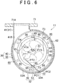
- FIG. 6 shows a cross-sectional structure of the turbine housing 11 along a line VI-VI of FIG. 4 . Further, an arrow RA in FIG. 6 indicates a direction of rotation of the turbine wheel 21.
- the base body 60 is provided with the four pillar portions 65 arranged at angular intervals of 90° in the circumferential direction.
- Each of the communication portions 66 is formed between corresponding ones of the pillar portions 65 that are adjacent to each other in the circumferential direction.
- the communication portions 66 have a circumferential length that is set longer than a circumferential length of the pillar portions 65.
- the circumferential length of the pillar portions 65 is set longer than the circumferential length of the slit portion 43.
- Circumferential rotational phases of the shell body 30 and the base body 60 are set on the basis of a concept that will be described below. That is, the thin-walled portion 32A of the lateral wall portion 32 of the shell body 30 is smaller in thickness than the other region of the lateral wall portion 32, and hence is likely to be deformed excessively when a fragment of the blade of the turbine wheel 21 hits the thin-walled portion 32A.
- the pillars 65 are provided on a traveling path of the fragment of the turbine wheel 21 moving from a main body of the turbine wheel 21 toward the thin-walled portion 32A. That is, the circumferential phases of the shell body 30 and the base body 60 are set such that that one of fragments flying from the main body of the turbine wheel 21 in all directions which may hit the thin-walled portion 32A of the shell body 30 is received by a region higher in strength than the thin-walled portion 32A before the fragment reaches the thin-walled portion 32A.
- a mode of setting these phases can be described as follows. It should be noted herein that one of tangential lines of the turbine wheel 21 which passes one end of the thin-walled portion 32A, namely, which passes a tangent point PT1 on an outer periphery of the turbine wheel 21 and a point PC1 at an end of the thin-walled portion 32A is defined as a tangential line T1. Further, that one of the tangential lines of the turbine wheel 21 which passes the other end of the thin-walled portion 32A, namely, which passes a tangent point PT2 on the outer periphery of the turbine wheel 21 and a point PC2 at an end of the thin-walled portion 32A is defined as a tangential line T2. In the turbine housing 11, the circumferential phases of the shell body 30 and the base body 60 are set such that each of the pillar portions 65 is located between these tangential lines T1 and T2.
- the frequency with which this fragment hits the pillar portion 65 located between the turbine wheel 21 and the thin-walled portion 32A is high.
- the shell body 30 is restrained from being excessively deformed due to the hitting of the fragment.
- Patterns of the traveling path of the fragment that has separated from the turbine wheel 21 will be exemplified below.
- this fragment moves on the tangential lines T1 and T2, and hits a corresponding one of the pillar portions 65 before reaching the thin-walled portion 32A of the shell body 30.
- FIGS. 7A and 7B A process of manufacturing the first shell body 40 will be described with reference to FIGS. 7A and 7B .
- a metal plate 140 having an oblong flat plate portion 141 and a protrusion portion 142 protruding from a long side 141A of this flat plate portion 141 is formed.
- the flat plate portion 141 of the metal plate 140 is bent into a cylindrical shape, and the reinforcement portion 42 having the slit portion 43 is formed. Further, the protrusion portion 142 is press-molded into the shape of the first divisional connection portion 41. Thus, the first shell body 40 is formed.
- Step A The reinforcement portion 42 of the first shell body 40 is fitted to the outside of the flange portion 62 of the base body 60. At this moment, the circumferential phases of the base body 60 and the first shell body 40 are adjusted such that the pillar portions 65 of the base body 60 are so located as to correspond to the tangential lines T1 and T2.
- Step B The lateral wall portion 53 of the second shell body 50 is fitted to the inside of the reinforcement portion 42 of the first shell body 40, and the lower end face 53B of the second shell body 50 is butted against the top face 62A of the flange portion 62 of the base body 60.
- Step C A brazing solder is arranged on respective joint portions of the first shell body 40, the second shell body 50, and the base body 60.
- Step D The first shell body 40, the second shell body 50, and the base body 60 are put into a kilt and heated. At this moment, the brazing solder melts and flows into gaps among the respective joint portions, and the first shell body 40, the second shell body 50, and the base body 60 are joined to one another.
- Step E The inlet flange 71 is fitted to the outside of the connection portion 31 of the shell body 30, and the outlet flange 72 is fitted to the outside of the cylinder portion 61 of the base body 60.
- Step F A brazing solder is arranged on a joint portion between the connection portion 31 of the shell body 30 and the inlet flange 71, and on a joint portion between the base body 60 and the outlet flange 72.
- Step G The shell body 30, the base body 60, the inlet flange 71, and the outlet flange 72 are put into a kilt and heated. At this moment, the brazing solder melts and flows into gaps among the respective joint portions, and the shell body 30, the base body 60, the inlet flange 71, and the outlet flange 72 are thereby joined to one another.
- the first shell body 40 is so provided as to include the reinforcement portion 42 superposed on the outer peripheral face 53A of the lateral wall portion 53 of the scroll portion 51. Further, the reinforcement portion 42 is so provided as to have the slit portion 43 that is partially discontinuous in the circumferential direction.
- the shell body 30 and the base body 60 are combined with each other such that the pillar portions 65 are so located as to intersect with those of the tangential lines T1 and T2 of the turbine wheel 21 which pass the points PC1 and PC2 at the end of the thin-walled portion 32A, namely, such that the pillar portions 65 are located on the traveling path of a fragment of the wheel 21 moving from the main body of the wheel 21 toward the thin-walled portion 32A.
- the amount of deformation of the second shell body 50 can be made small when the fragment of the wheel 21 hits the lateral wall portion 53 of the scroll portion 51.
- the reinforcement portion 42 be structured not to include the slit portion 43. In the case of such a structure, the operation of superposing the reinforcement portion 42 on the lateral wall portion 53 of the scroll portion 51 is troublesome in manufacturing the shell body 50.
- the reinforcement portion 42 is provided with the slit portion 43. Therefore, the operability in superposing the reinforcement portion 42 on the outer peripheral face 53A of the lateral wall portion 53 of the scroll portion 51 can be made good.
- the lateral wall portion 53 of the second shell body 50 is fitted to the inside of the reinforcement portion 42 of the first shell body 40.
- the first shell body 40 is structured with the first divisional connection portion 41 and the reinforcement portion 42 made of the same material and formed integrally with each other.
- the structure of the shell body 40 can also be changed as will be described below. That is, the first shell body 40 can also be constructed by forming the first divisional connection portion 41 and the reinforcement portion 42 separately from each other and joining these components to each other through welding or the like.
- the region corresponding to the connection portion 31 can also be made of the same material as the reinforcement portion 42 and formed integrally therewith to constitute the first shell body 40.
- the second shell body 50 is structured with the second divisional connection portion 54 and the scroll portion 51 made of the same material and formed integrally with each other.
- the structure of the shell body 50 can also be changed as will be described below. That is, the second shell body 50 can also be constructed by forming the second divisional connection portion 54 and the scroll portion 51 separately from each other and joining these components to each other through welding or the like.
- the region corresponding to the connection portion 31 can also be made of the same material as the scroll portion 51 and formed integrally therewith to constitute the second shell body 50.
- the first divisional connection portion 41 and the second divisional connection portion 54 which constitute the connection portion 31, are constructed as part of the first shell body 40 and part of the second shell body 50 respectively.
- the connection portion 31 can also be formed separately from the respective shell bodies.
- the first divisional connection portion 41 and the second divisional connection portion 54 can be formed separately from the respective shells and joined to each other to constitute the connection portion 31.
- the connection portion 31 with the first divisional connection portion 41 and the second divisional connection portion 54 formed separately from the respective shell bodies and joined to each other can also be formed as a single element serving as the connection portion 31.
- the slit portion 43 is formed in such a shape that one end face and the other end face of the reinforcement portion 42 extend parallel to each other.
- the slit portion 43 is not limited to this shape.
- the slit portion 43 can also be formed in such a shape that the clearance between one end face and the other end face of the reinforcement portion 42 gradually increases from one end to the other end in the width direction of the reinforcement portion 42.
- the base body 60 is structured to include the four pillar portions 65 and the four communication portions 66.
- the number of the pillar portions 65 or the communication portions 66 can be changed to an integer between 1 and 3 or an integer equal to or larger than 5.
- the pillar portions 65 are provided inside those of the tangential lines T1 and T2 of the turbine wheel 21 which pass both the end points of the slit portion 43 respectively.
- the concrete contents of the aforementioned structure are not limited as described above.
- the pillar portions 65 can also be positioned such that only one of the tangential lines T1 and T2 passes the pillar portions 65.
- the pillar portions 65 are provided on the traveling path of the fragment separating from the main body of the turbine wheel 21 and moving toward the thin-walled portion 32A, the positional relationship between the pillar portions 65 and the slit portion 43, and the sizes and shapes of these elements can be appropriately changed.
- the turbine housing 11 is constructed with the first shell body 40, the second shell body 50, the base body 60, the inlet flange 71, and the outlet flange 72 formed separately from one another and joined to one another.
- the turbine housing 11 is not limited to this construction.
- at least one of the aforementioned respective structural bodies formed separately from one another can also be formed as a plurality of further divided structural bodies.
- at least two of the aforementioned respective structural bodies except the first shell body 40 and the second shell body 50 can also be formed as a single structural body.
- the sheet metal shell bodies are adopted as the first shell body 40 and the second shell body 50.
- the first shell body 40 and the second shell body 50 can also be replaced with cast or resinous shell bodies.
- the cast base body is adopted as the base body 60.
- the base body 60 can also be replaced with a cast or resinous base body.
- the invention is applied only to the former of the turbine housing 11 and the compressor housing 12.
- the invention can also be applied to the respective housings. Further, the invention can also be applied only to the compressor housing 12.
Landscapes
- Engineering & Computer Science (AREA)
- Mechanical Engineering (AREA)
- General Engineering & Computer Science (AREA)
- Supercharger (AREA)
Claims (9)
- Turbolader-Radgehäuse, der einen Schalenkörper (30) mit einem Schneckenabschnitt (51) und einen Grundkörper (60) mit einem Unterbringungsabschnitt (63), in welchem ein Rad untergebracht ist, enthält, wobei ein Gasweg zwischen Schalenkörper (30) und Grundkörper (60) gebildet ist und wobei
der Schalenkörper (30) aus einem ersten Schalenkörper (40) und einem zweiten Schalenkörper (50), welche separat voneinander gebildet und miteinander kombiniert sind, besteht,
der zweite Schalenkörper (50) den Schneckenabschnitt (51) enthält,
der Unterbringungsabschnitt (60) eine Radkammer (64), in welcher das Rad untergebracht ist, einen Kommunikationsabschnitt (66), der einen Gasfluss von dem Gasweg zu der Radkammer (64) erlaubt, und einen Säulenabschnitt (65) angrenzend an dem Kommunikationsabschnitt (66), um den Gasfluss von dem Gasweg zur Radkammer zu blockieren, enthält,
der erste Schalenkörper (40) einen Verstärkungsabschnitt (42) enthält, der eine periphere Innenfläche oder eine periphere Außenfläche einer peripheren Wand des Schneckenabschnittes (51) überlagert,
dadurch gekennzeichnet, dass
der Verstärkungsabschnitt (42) einen Schlitzabschnitt (43) hat, der den Verstärkungsabschnitt in der Umfangsrichtung teilweise nicht-durchgängig macht, und
der Säulenabschnitt (65) so bereitgestellt ist, dass er sich mit der tangentialen Linie des Rades, welche den Schlitzabschnitt (43) passiert, schneidet. - Turbolader-Radgehäuse nach Anspruch 1, dadurch gekennzeichnet, dass der erste Schalenkörper (40) und der zweite Schalenkörper (50) als Metallblech-Schalenkörper bereitgestellt sind.
- Turbolader-Radgehäuse nach Anspruch 1 oder 2, dadurch gekennzeichnet, dass der Schalenkörper einen Verbindungsabschnitt (31) enthält, welcher den Schneckenabschnitt mit einem Abgas- oder einem Luftsaugrohr verbindet,
der erste Schalenkörper (40) einen ersten teilenden Verbindungsabschnitt (41) als Teil des Verbindungsabschnittes enthält,
der zweite Schalenkörper (50) einen zweiten teilenden Verbindungsabschnitt (54), der einen Teil des Verbindungsabschnittes bildet, enthält und
der Verbindungsabschnitt (31) aus dem ersten teilenden Verbindungsabschnitt (41) und dem zweiten teilenden Verbindungsabschnitt (54) besteht, welche miteinander kombiniert sind. - Turbolader-Radgehäuse nach Anspruch 3, dadurch gekennzeichnet, dass der erste Schalenkörper (40) aus einer Metallplatte gebildet ist, die einen rechteckigen, flachen Plattenabschnitt (141) und einen hervorstehenden Abschnitt (142), welcher von einer langen Seite des flachen Plattenabschnittes hervorsteht, aufweist,
der Verstärkungsabschnitt (42) gebildet ist, indem der Flach-Plattenabschnitt zu einer zylindrischen Form verarbeitet wurde, und
der erste teilende Verbindungsabschnitt (41) gebildet ist, indem der hervorstehende Abschnitt (142) zu einer zylindrischen Form verarbeitet wurde. - Turbolader-Radgehäuse nach einem der Ansprüche 1 bis 4, dadurch gekennzeichnet, dass der Grundkörper einen Flanschabschnitt (62) beinhaltet, welcher radial auswärts über den Unterbringungsabschnitt (63) hervorsteht, und
das Radgehäuse gebildet ist, indem einer von dem Verstärkungsabschnitt (42) der ersten Schalenkörpers (40) oder dem Schneckenabschnitt (51) des zweiten Schalenkörpers (50) an einer äußeren Peripherie des Flanschabschnittes (62) des Grundkörpers angebracht wurde und der andere von dem Verstärkungsabschnitt (42) und dem Schneckenabschnitt (51) an eine innere Peripherie des einen von dem Verstärkungsabschnitt (42) und dem Schneckenabschnitt (51), welcher an der äußeren Peripherie des Flanschabschnittes (62) angebracht ist, angebracht wurde. - Turbolader-Radgehäuse nach einem der Ansprüche 1 bis 5, dadurch gekennzeichnet, dass der Säulenabschnitt (65) in einer Umfangsrichtung länger als der Schlitzabschnitt (43) ist.
- Turbolader-Turbinengehäuse, dadurch gekennzeichnet, dass es auf die gleiche Weise wie das Radgehäuse nach einem Ansprüche 1 bis 6 konstruiert ist.
- Turbolader-Kompressorgehäuse, dadurch gekennzeichnet, dass es auf die gleiche Weise wie das Radgehäuse nach einem Ansprüche 1 bis 6 konstruiert ist.
- Turbolader, der Radgehäuse nach einem der Ansprüche 1 bis 6 enthält.
Applications Claiming Priority (2)
| Application Number | Priority Date | Filing Date | Title |
|---|---|---|---|
| JP2010023404A JP4905565B2 (ja) | 2010-02-04 | 2010-02-04 | ターボチャージャおよびそのホイールハウジング |
| PCT/IB2011/000309 WO2011095892A2 (en) | 2010-02-04 | 2011-02-02 | Turbocharger and turbocharger wheel housing |
Publications (2)
| Publication Number | Publication Date |
|---|---|
| EP2531701A2 EP2531701A2 (de) | 2012-12-12 |
| EP2531701B1 true EP2531701B1 (de) | 2017-10-25 |
Family
ID=44355875
Family Applications (1)
| Application Number | Title | Priority Date | Filing Date |
|---|---|---|---|
| EP11712001.4A Not-in-force EP2531701B1 (de) | 2010-02-04 | 2011-02-02 | Turbolader und gehäuse für ein turboladerrad |
Country Status (5)
| Country | Link |
|---|---|
| US (1) | US9121281B2 (de) |
| EP (1) | EP2531701B1 (de) |
| JP (1) | JP4905565B2 (de) |
| CN (1) | CN102741507B (de) |
| WO (1) | WO2011095892A2 (de) |
Families Citing this family (10)
| Publication number | Priority date | Publication date | Assignee | Title |
|---|---|---|---|---|
| JP5769407B2 (ja) * | 2010-02-01 | 2015-08-26 | 三菱重工業株式会社 | 板金タービンハウジング |
| DE102012109807A1 (de) * | 2012-10-15 | 2014-04-17 | Benteler Automobiltechnik Gmbh | Abgasturbolader |
| US9945258B2 (en) | 2014-10-10 | 2018-04-17 | Ford Global Technologies, Llc | Sheet metal turbine housing with cellular structure reinforcement |
| US20160326893A1 (en) * | 2015-05-07 | 2016-11-10 | Icr Turbine Engine Corporation | Ceramic turbine volute |
| US10544703B2 (en) | 2017-01-30 | 2020-01-28 | Garrett Transportation I Inc. | Sheet metal turbine housing with cast core |
| US10436069B2 (en) * | 2017-01-30 | 2019-10-08 | Garrett Transportation I Inc. | Sheet metal turbine housing with biaxial volute configuration |
| US10494955B2 (en) | 2017-01-30 | 2019-12-03 | Garrett Transportation I Inc. | Sheet metal turbine housing with containment dampers |
| US10472988B2 (en) * | 2017-01-30 | 2019-11-12 | Garrett Transportation I Inc. | Sheet metal turbine housing and related turbocharger systems |
| US10690144B2 (en) | 2017-06-27 | 2020-06-23 | Garrett Transportation I Inc. | Compressor housings and fabrication methods |
| US11732729B2 (en) * | 2021-01-26 | 2023-08-22 | Garrett Transportation I Inc | Sheet metal turbine housing |
Family Cites Families (10)
| Publication number | Priority date | Publication date | Assignee | Title |
|---|---|---|---|---|
| DE19640654A1 (de) | 1996-10-02 | 1998-04-09 | Asea Brown Boveri | Berstschutzvorrichtung für Radialturbinen von Turboladern |
| US6059524A (en) * | 1998-04-20 | 2000-05-09 | United Technologies Corporation | Penetration resistant fan casing for a turbine engine |
| DE10028160C2 (de) | 2000-06-07 | 2003-03-27 | Borgwarner Inc | Gehäusegruppe für die Turbine eines Abgas-Turboladers |
| DE10125250C5 (de) * | 2001-05-23 | 2007-03-29 | Man Diesel Se | Axialturbine eines Abgastruboladers mit internem Berstschutz |
| JP4448064B2 (ja) | 2005-06-24 | 2010-04-07 | トヨタ自動車株式会社 | タービンハウジング |
| US20070071605A1 (en) * | 2005-09-23 | 2007-03-29 | General Electric Company | Integrated nozzle and bucket wheels for reaction steam turbine stationary components and related method |
| GB0614392D0 (en) * | 2006-07-20 | 2006-08-30 | Cummins Turbo Tech Ltd | Turbine Housing for a turbocharger |
| JP4847842B2 (ja) * | 2006-10-25 | 2011-12-28 | アイシン高丘株式会社 | タービンハウジング |
| DE102007055615A1 (de) * | 2007-11-20 | 2009-05-28 | Mann + Hummel Gmbh | Gehäuse für einen Radialverdichter |
| JP2011021573A (ja) * | 2009-07-17 | 2011-02-03 | Toyota Motor Corp | ターボチャージャ |
-
2010
- 2010-02-04 JP JP2010023404A patent/JP4905565B2/ja not_active Expired - Fee Related
-
2011
- 2011-02-02 WO PCT/IB2011/000309 patent/WO2011095892A2/en not_active Ceased
- 2011-02-02 EP EP11712001.4A patent/EP2531701B1/de not_active Not-in-force
- 2011-02-02 CN CN201180008391.6A patent/CN102741507B/zh not_active Expired - Fee Related
- 2011-02-02 US US13/574,648 patent/US9121281B2/en not_active Expired - Fee Related
Non-Patent Citations (1)
| Title |
|---|
| None * |
Also Published As
| Publication number | Publication date |
|---|---|
| JP4905565B2 (ja) | 2012-03-28 |
| US20120288364A1 (en) | 2012-11-15 |
| WO2011095892A3 (en) | 2011-12-01 |
| US9121281B2 (en) | 2015-09-01 |
| WO2011095892A2 (en) | 2011-08-11 |
| CN102741507A (zh) | 2012-10-17 |
| JP2011163129A (ja) | 2011-08-25 |
| CN102741507B (zh) | 2014-12-31 |
| EP2531701A2 (de) | 2012-12-12 |
Similar Documents
| Publication | Publication Date | Title |
|---|---|---|
| EP2531701B1 (de) | Turbolader und gehäuse für ein turboladerrad | |
| JP5984446B2 (ja) | タービンハウジングアセンブリおよびタービンハウジングアセンブリの製造方法 | |
| KR101994511B1 (ko) | 노즐 링 | |
| CN104379898B (zh) | 涡轮壳体组件 | |
| EP3260670B1 (de) | Turbinengehäuse | |
| JP4759062B2 (ja) | ターボチャージャおよびターボチャージャの製造方法 | |
| CN103518036A (zh) | 旋转发动机转子 | |
| EP2524128B1 (de) | Radgehäuse für einen turbolader | |
| JP4847842B2 (ja) | タービンハウジング | |
| EP3263865B1 (de) | Mechanismus eines verstellbaren leitapparats für einen turbolader und abgasturbolader vom typ mit verstellbarer geometrie | |
| CN106460646B (zh) | 涡轮外壳、涡轮、用于铸造涡轮外壳的型芯、以及涡轮外壳的制造方法 | |
| US20030205047A1 (en) | Turbine casing for an exhaust turbocharger made by casting | |
| WO2011104596A2 (en) | Turbocharger and wheel housing thereof | |
| WO2020079969A1 (ja) | 可変容量型過給機 | |
| EP1287236B1 (de) | Gegossenes spiralgehäuse für einen turbolader |
Legal Events
| Date | Code | Title | Description |
|---|---|---|---|
| PUAI | Public reference made under article 153(3) epc to a published international application that has entered the european phase |
Free format text: ORIGINAL CODE: 0009012 |
|
| 17P | Request for examination filed |
Effective date: 20120529 |
|
| AK | Designated contracting states |
Kind code of ref document: A2 Designated state(s): AL AT BE BG CH CY CZ DE DK EE ES FI FR GB GR HR HU IE IS IT LI LT LU LV MC MK MT NL NO PL PT RO RS SE SI SK SM TR |
|
| RAP1 | Party data changed (applicant data changed or rights of an application transferred) |
Owner name: TOYOTA JIDOSHA KABUSHIKI KAISHA |
|
| DAX | Request for extension of the european patent (deleted) | ||
| STAA | Information on the status of an ep patent application or granted ep patent |
Free format text: STATUS: EXAMINATION IS IN PROGRESS |
|
| 17Q | First examination report despatched |
Effective date: 20170124 |
|
| GRAP | Despatch of communication of intention to grant a patent |
Free format text: ORIGINAL CODE: EPIDOSNIGR1 |
|
| STAA | Information on the status of an ep patent application or granted ep patent |
Free format text: STATUS: GRANT OF PATENT IS INTENDED |
|
| INTG | Intention to grant announced |
Effective date: 20170523 |
|
| GRAS | Grant fee paid |
Free format text: ORIGINAL CODE: EPIDOSNIGR3 |
|
| GRAA | (expected) grant |
Free format text: ORIGINAL CODE: 0009210 |
|
| STAA | Information on the status of an ep patent application or granted ep patent |
Free format text: STATUS: THE PATENT HAS BEEN GRANTED |
|
| AK | Designated contracting states |
Kind code of ref document: B1 Designated state(s): AL AT BE BG CH CY CZ DE DK EE ES FI FR GB GR HR HU IE IS IT LI LT LU LV MC MK MT NL NO PL PT RO RS SE SI SK SM TR |
|
| REG | Reference to a national code |
Ref country code: GB Ref legal event code: FG4D |
|
| REG | Reference to a national code |
Ref country code: CH Ref legal event code: EP |
|
| REG | Reference to a national code |
Ref country code: AT Ref legal event code: REF Ref document number: 940159 Country of ref document: AT Kind code of ref document: T Effective date: 20171115 |
|
| REG | Reference to a national code |
Ref country code: IE Ref legal event code: FG4D |
|
| REG | Reference to a national code |
Ref country code: DE Ref legal event code: R096 Ref document number: 602011042667 Country of ref document: DE |
|
| REG | Reference to a national code |
Ref country code: FR Ref legal event code: PLFP Year of fee payment: 8 |
|
| REG | Reference to a national code |
Ref country code: NL Ref legal event code: MP Effective date: 20171025 |
|
| REG | Reference to a national code |
Ref country code: LT Ref legal event code: MG4D |
|
| REG | Reference to a national code |
Ref country code: AT Ref legal event code: MK05 Ref document number: 940159 Country of ref document: AT Kind code of ref document: T Effective date: 20171025 |
|
| PG25 | Lapsed in a contracting state [announced via postgrant information from national office to epo] |
Ref country code: NL Free format text: LAPSE BECAUSE OF FAILURE TO SUBMIT A TRANSLATION OF THE DESCRIPTION OR TO PAY THE FEE WITHIN THE PRESCRIBED TIME-LIMIT Effective date: 20171025 |
|
| PG25 | Lapsed in a contracting state [announced via postgrant information from national office to epo] |
Ref country code: ES Free format text: LAPSE BECAUSE OF FAILURE TO SUBMIT A TRANSLATION OF THE DESCRIPTION OR TO PAY THE FEE WITHIN THE PRESCRIBED TIME-LIMIT Effective date: 20171025 Ref country code: SE Free format text: LAPSE BECAUSE OF FAILURE TO SUBMIT A TRANSLATION OF THE DESCRIPTION OR TO PAY THE FEE WITHIN THE PRESCRIBED TIME-LIMIT Effective date: 20171025 Ref country code: FI Free format text: LAPSE BECAUSE OF FAILURE TO SUBMIT A TRANSLATION OF THE DESCRIPTION OR TO PAY THE FEE WITHIN THE PRESCRIBED TIME-LIMIT Effective date: 20171025 Ref country code: NO Free format text: LAPSE BECAUSE OF FAILURE TO SUBMIT A TRANSLATION OF THE DESCRIPTION OR TO PAY THE FEE WITHIN THE PRESCRIBED TIME-LIMIT Effective date: 20180125 Ref country code: LT Free format text: LAPSE BECAUSE OF FAILURE TO SUBMIT A TRANSLATION OF THE DESCRIPTION OR TO PAY THE FEE WITHIN THE PRESCRIBED TIME-LIMIT Effective date: 20171025 |
|
| PG25 | Lapsed in a contracting state [announced via postgrant information from national office to epo] |
Ref country code: HR Free format text: LAPSE BECAUSE OF FAILURE TO SUBMIT A TRANSLATION OF THE DESCRIPTION OR TO PAY THE FEE WITHIN THE PRESCRIBED TIME-LIMIT Effective date: 20171025 Ref country code: IS Free format text: LAPSE BECAUSE OF FAILURE TO SUBMIT A TRANSLATION OF THE DESCRIPTION OR TO PAY THE FEE WITHIN THE PRESCRIBED TIME-LIMIT Effective date: 20180225 Ref country code: GR Free format text: LAPSE BECAUSE OF FAILURE TO SUBMIT A TRANSLATION OF THE DESCRIPTION OR TO PAY THE FEE WITHIN THE PRESCRIBED TIME-LIMIT Effective date: 20180126 Ref country code: RS Free format text: LAPSE BECAUSE OF FAILURE TO SUBMIT A TRANSLATION OF THE DESCRIPTION OR TO PAY THE FEE WITHIN THE PRESCRIBED TIME-LIMIT Effective date: 20171025 Ref country code: AT Free format text: LAPSE BECAUSE OF FAILURE TO SUBMIT A TRANSLATION OF THE DESCRIPTION OR TO PAY THE FEE WITHIN THE PRESCRIBED TIME-LIMIT Effective date: 20171025 Ref country code: LV Free format text: LAPSE BECAUSE OF FAILURE TO SUBMIT A TRANSLATION OF THE DESCRIPTION OR TO PAY THE FEE WITHIN THE PRESCRIBED TIME-LIMIT Effective date: 20171025 Ref country code: BG Free format text: LAPSE BECAUSE OF FAILURE TO SUBMIT A TRANSLATION OF THE DESCRIPTION OR TO PAY THE FEE WITHIN THE PRESCRIBED TIME-LIMIT Effective date: 20180125 |
|
| REG | Reference to a national code |
Ref country code: DE Ref legal event code: R097 Ref document number: 602011042667 Country of ref document: DE |
|
| PG25 | Lapsed in a contracting state [announced via postgrant information from national office to epo] |
Ref country code: CZ Free format text: LAPSE BECAUSE OF FAILURE TO SUBMIT A TRANSLATION OF THE DESCRIPTION OR TO PAY THE FEE WITHIN THE PRESCRIBED TIME-LIMIT Effective date: 20171025 Ref country code: SK Free format text: LAPSE BECAUSE OF FAILURE TO SUBMIT A TRANSLATION OF THE DESCRIPTION OR TO PAY THE FEE WITHIN THE PRESCRIBED TIME-LIMIT Effective date: 20171025 Ref country code: EE Free format text: LAPSE BECAUSE OF FAILURE TO SUBMIT A TRANSLATION OF THE DESCRIPTION OR TO PAY THE FEE WITHIN THE PRESCRIBED TIME-LIMIT Effective date: 20171025 Ref country code: CY Free format text: LAPSE BECAUSE OF FAILURE TO SUBMIT A TRANSLATION OF THE DESCRIPTION OR TO PAY THE FEE WITHIN THE PRESCRIBED TIME-LIMIT Effective date: 20171025 Ref country code: DK Free format text: LAPSE BECAUSE OF FAILURE TO SUBMIT A TRANSLATION OF THE DESCRIPTION OR TO PAY THE FEE WITHIN THE PRESCRIBED TIME-LIMIT Effective date: 20171025 |
|
| PG25 | Lapsed in a contracting state [announced via postgrant information from national office to epo] |
Ref country code: RO Free format text: LAPSE BECAUSE OF FAILURE TO SUBMIT A TRANSLATION OF THE DESCRIPTION OR TO PAY THE FEE WITHIN THE PRESCRIBED TIME-LIMIT Effective date: 20171025 Ref country code: SM Free format text: LAPSE BECAUSE OF FAILURE TO SUBMIT A TRANSLATION OF THE DESCRIPTION OR TO PAY THE FEE WITHIN THE PRESCRIBED TIME-LIMIT Effective date: 20171025 Ref country code: PL Free format text: LAPSE BECAUSE OF FAILURE TO SUBMIT A TRANSLATION OF THE DESCRIPTION OR TO PAY THE FEE WITHIN THE PRESCRIBED TIME-LIMIT Effective date: 20171025 Ref country code: IT Free format text: LAPSE BECAUSE OF FAILURE TO SUBMIT A TRANSLATION OF THE DESCRIPTION OR TO PAY THE FEE WITHIN THE PRESCRIBED TIME-LIMIT Effective date: 20171025 |
|
| PLBE | No opposition filed within time limit |
Free format text: ORIGINAL CODE: 0009261 |
|
| STAA | Information on the status of an ep patent application or granted ep patent |
Free format text: STATUS: NO OPPOSITION FILED WITHIN TIME LIMIT |
|
| REG | Reference to a national code |
Ref country code: CH Ref legal event code: PL |
|
| PG25 | Lapsed in a contracting state [announced via postgrant information from national office to epo] |
Ref country code: MC Free format text: LAPSE BECAUSE OF FAILURE TO SUBMIT A TRANSLATION OF THE DESCRIPTION OR TO PAY THE FEE WITHIN THE PRESCRIBED TIME-LIMIT Effective date: 20171025 |
|
| REG | Reference to a national code |
Ref country code: DE Ref legal event code: R084 Ref document number: 602011042667 Country of ref document: DE |
|
| 26N | No opposition filed |
Effective date: 20180726 |
|
| REG | Reference to a national code |
Ref country code: GB Ref legal event code: 746 Effective date: 20180928 |
|
| REG | Reference to a national code |
Ref country code: BE Ref legal event code: MM Effective date: 20180228 |
|
| PG25 | Lapsed in a contracting state [announced via postgrant information from national office to epo] |
Ref country code: LI Free format text: LAPSE BECAUSE OF NON-PAYMENT OF DUE FEES Effective date: 20180228 Ref country code: LU Free format text: LAPSE BECAUSE OF NON-PAYMENT OF DUE FEES Effective date: 20180202 Ref country code: SI Free format text: LAPSE BECAUSE OF FAILURE TO SUBMIT A TRANSLATION OF THE DESCRIPTION OR TO PAY THE FEE WITHIN THE PRESCRIBED TIME-LIMIT Effective date: 20171025 Ref country code: CH Free format text: LAPSE BECAUSE OF NON-PAYMENT OF DUE FEES Effective date: 20180228 |
|
| REG | Reference to a national code |
Ref country code: IE Ref legal event code: MM4A |
|
| PG25 | Lapsed in a contracting state [announced via postgrant information from national office to epo] |
Ref country code: IE Free format text: LAPSE BECAUSE OF NON-PAYMENT OF DUE FEES Effective date: 20180202 |
|
| PG25 | Lapsed in a contracting state [announced via postgrant information from national office to epo] |
Ref country code: BE Free format text: LAPSE BECAUSE OF NON-PAYMENT OF DUE FEES Effective date: 20180228 |
|
| PGFP | Annual fee paid to national office [announced via postgrant information from national office to epo] |
Ref country code: DE Payment date: 20190122 Year of fee payment: 9 Ref country code: FR Payment date: 20190111 Year of fee payment: 9 Ref country code: GB Payment date: 20190130 Year of fee payment: 9 |
|
| PG25 | Lapsed in a contracting state [announced via postgrant information from national office to epo] |
Ref country code: MT Free format text: LAPSE BECAUSE OF NON-PAYMENT OF DUE FEES Effective date: 20180202 |
|
| PG25 | Lapsed in a contracting state [announced via postgrant information from national office to epo] |
Ref country code: TR Free format text: LAPSE BECAUSE OF FAILURE TO SUBMIT A TRANSLATION OF THE DESCRIPTION OR TO PAY THE FEE WITHIN THE PRESCRIBED TIME-LIMIT Effective date: 20171025 |
|
| PG25 | Lapsed in a contracting state [announced via postgrant information from national office to epo] |
Ref country code: HU Free format text: LAPSE BECAUSE OF FAILURE TO SUBMIT A TRANSLATION OF THE DESCRIPTION OR TO PAY THE FEE WITHIN THE PRESCRIBED TIME-LIMIT; INVALID AB INITIO Effective date: 20110202 Ref country code: PT Free format text: LAPSE BECAUSE OF FAILURE TO SUBMIT A TRANSLATION OF THE DESCRIPTION OR TO PAY THE FEE WITHIN THE PRESCRIBED TIME-LIMIT Effective date: 20171025 |
|
| PG25 | Lapsed in a contracting state [announced via postgrant information from national office to epo] |
Ref country code: MK Free format text: LAPSE BECAUSE OF NON-PAYMENT OF DUE FEES Effective date: 20171025 |
|
| PG25 | Lapsed in a contracting state [announced via postgrant information from national office to epo] |
Ref country code: AL Free format text: LAPSE BECAUSE OF FAILURE TO SUBMIT A TRANSLATION OF THE DESCRIPTION OR TO PAY THE FEE WITHIN THE PRESCRIBED TIME-LIMIT Effective date: 20171025 |
|
| REG | Reference to a national code |
Ref country code: DE Ref legal event code: R119 Ref document number: 602011042667 Country of ref document: DE |
|
| GBPC | Gb: european patent ceased through non-payment of renewal fee |
Effective date: 20200202 |
|
| PG25 | Lapsed in a contracting state [announced via postgrant information from national office to epo] |
Ref country code: FR Free format text: LAPSE BECAUSE OF NON-PAYMENT OF DUE FEES Effective date: 20200229 Ref country code: DE Free format text: LAPSE BECAUSE OF NON-PAYMENT OF DUE FEES Effective date: 20200901 Ref country code: GB Free format text: LAPSE BECAUSE OF NON-PAYMENT OF DUE FEES Effective date: 20200202 |