EP2829666B1 - Einlaufgarnitur für einen Spülkasten - Google Patents
Einlaufgarnitur für einen Spülkasten Download PDFInfo
- Publication number
- EP2829666B1 EP2829666B1 EP13177821.9A EP13177821A EP2829666B1 EP 2829666 B1 EP2829666 B1 EP 2829666B1 EP 13177821 A EP13177821 A EP 13177821A EP 2829666 B1 EP2829666 B1 EP 2829666B1
- Authority
- EP
- European Patent Office
- Prior art keywords
- pipe
- deflection
- inlet fitting
- outlet pipe
- water
- Prior art date
- Legal status (The legal status is an assumption and is not a legal conclusion. Google has not performed a legal analysis and makes no representation as to the accuracy of the status listed.)
- Active
Links
Images


Classifications
-
- F—MECHANICAL ENGINEERING; LIGHTING; HEATING; WEAPONS; BLASTING
- F16—ENGINEERING ELEMENTS AND UNITS; GENERAL MEASURES FOR PRODUCING AND MAINTAINING EFFECTIVE FUNCTIONING OF MACHINES OR INSTALLATIONS; THERMAL INSULATION IN GENERAL
- F16K—VALVES; TAPS; COCKS; ACTUATING-FLOATS; DEVICES FOR VENTING OR AERATING
- F16K31/00—Actuating devices; Operating means; Releasing devices
- F16K31/12—Actuating devices; Operating means; Releasing devices actuated by fluid
- F16K31/18—Actuating devices; Operating means; Releasing devices actuated by fluid actuated by a float
- F16K31/34—Actuating devices; Operating means; Releasing devices actuated by fluid actuated by a float acting on pilot valve controlling the cut-off apparatus
-
- E—FIXED CONSTRUCTIONS
- E03—WATER SUPPLY; SEWERAGE
- E03D—WATER-CLOSETS OR URINALS WITH FLUSHING DEVICES; FLUSHING VALVES THEREFOR
- E03D9/00—Sanitary or other accessories for lavatories ; Devices for cleaning or disinfecting the toilet room or the toilet bowl; Devices for eliminating smells
- E03D9/14—Noise-reducing means combined with flushing valves
-
- F—MECHANICAL ENGINEERING; LIGHTING; HEATING; WEAPONS; BLASTING
- F16—ENGINEERING ELEMENTS AND UNITS; GENERAL MEASURES FOR PRODUCING AND MAINTAINING EFFECTIVE FUNCTIONING OF MACHINES OR INSTALLATIONS; THERMAL INSULATION IN GENERAL
- F16K—VALVES; TAPS; COCKS; ACTUATING-FLOATS; DEVICES FOR VENTING OR AERATING
- F16K47/00—Means in valves for absorbing fluid energy
- F16K47/02—Means in valves for absorbing fluid energy for preventing water-hammer or noise
-
- E—FIXED CONSTRUCTIONS
- E03—WATER SUPPLY; SEWERAGE
- E03D—WATER-CLOSETS OR URINALS WITH FLUSHING DEVICES; FLUSHING VALVES THEREFOR
- E03D1/00—Water flushing devices with cisterns ; Setting up a range of flushing devices or water-closets; Combinations of several flushing devices
- E03D1/30—Valves for high or low level cisterns; Their arrangement ; Flushing mechanisms in the cistern, optionally with provisions for a pre-or a post- flushing and for cutting off the flushing mechanism in case of leakage
- E03D1/32—Arrangement of inlet valves
Definitions
- the present invention relates to an inlet fitting for a cistern according to the preamble of claim 1.
- Inlet fittings are used for filling cisterns of sanitary items, such as toilets or urinals.
- sanitary items such as toilets or urinals.
- an inlet fitting for a cistern has become known. Good results with regard to the prevention of malfunctions have been achieved with this inlet fitting.
- the noise are after the EP 1 175 576 produced inlet fittings advantageous.
- a drain device has become known, but which is disadvantageous in terms of noise.
- the invention has for its object to provide an inlet fitting which is as quiet as possible when flow of rinse water.
- an inlet fitting for filling a cistern comprises a housing, a housing arranged in the water supply channel having an input and an output, and arranged in a water passage channel float-controlled valve, which Water supply channel locks or releases during filling.
- an expansion element is arranged in the water flow channel seen in the flow direction after the valve, which increases the cross section of the water guide channel, so that an expansion of the water jet takes place and the flow rate is reduced.
- the expansion element is arranged in the flow direction in front of an outlet tube which forms the outlet.
- the expansion element comprises a tube element with a tube end and a deflection element with a deflection surface.
- the tube element is directed with its tube end on the deflection surface, wherein the tube end is spaced from the deflection surface. By this distance, the water jet impinges on the deflection surface as a free water jet and is deflected there.
- the pipe element and the deflection surface are part of the water supply channel or limit the water supply channel in the corresponding area.
- the deflection surface is formed as a curved surface.
- the tubular element can therefore be directed to a curved or a flat surface, wherein the tube end is located at a distance from said surface.
- the tubular element can be directed in different directions on the deflection surface be. Particularly preferably, however, the tube element is directed with the central axis of the tube at right angles to the surface.
- the deflection surface extends from an intersection of the central axis of the tubular element rounded to the tubular element.
- the pipe element is directed with its pipe end to this intersection.
- the deflection surface thus forms a kind of screen or, seen in cross section, has the shape of a parabola, the water jet impinging on the vertex coming from the pipe end.
- the deflection surface may also be formed conical, wherein the tip of the cone is directed into the center of the pipe end and extends from there tapered away from the pipe end.
- the lateral surface of the cone may be formed at least partially, in particular rounded relative to the tip. The rounding can thereby pass over the surface which is provided by the parabola.
- the deflection surface in the cross-sectional shape of the parabola at the vertex may have a cone whose tip is directed against the pipe end.
- the transition between conical surface and parabolic surface is preferably rounded.
- the deflection surface defines an interior into which the pipe element protrudes, wherein an annular gap is present between the outside of the pipe element and the deflection surface.
- the cross section of said gap is greater than the cross section of the tubular element.
- the cross section of the gap is adjustable or self-regulating to the line pressure.
- the tube element Opposite the tube end, the tube element has a tube beginning, which preferably represents a part of the float-controlled valve.
- a valve stem of the float-controlled valve protrudes into the beginning of the pipe forms a corresponding sealing point with the pipe beginning.
- the pipe element in a particular preferred embodiment of a pipe bend, which is preferably bent by 90 °.
- the pipe element extends in the installed position at least partially below the deflecting element.
- the pipe element protrudes laterally into an outlet pipe, which likewise constitutes a part of the drain grate or of the housing.
- the water supply channel comprises an outlet pipe which extends vertically in the installed position, wherein the deflection surface deflects the water into the outlet pipe and wherein the flushing water can be dispensed into a cistern through the outlet pipe.
- the central axis of the outlet pipe runs in sections collinear or parallel to the central axis of the tubular element.
- the deflection surface extends in the region of the transition in or in the direction of the outlet pipe in alignment with the outlet pipe.
- the deflection element closes the outlet pipe in the vertical direction towards the top.
- the deflection element has the shape of a lid.
- the deflecting element and / or the outlet pipe in particular in the region of the transition between deflecting element and outlet pipe, have at least one air passage. Through this passage of air can be sucked in the case of a negative pressure in the water guide duct over this air duct air from the cistern.
- the vent passage is behind a cover, wherein the cover is spaced from the vent passage and this covered with respect to the overflowing water.
- the vent passage in the direction of flow in the form of a narrow slit, the shorter clear width is overflowed by the rinse water.
- the deflection surface comprises at least one flow divider, in particular in the form of a cone extending from the deflection surface.
- the expansion element is a diffuser.
- the expansion element comprises a diffuser, which, viewed in the flow direction, is arranged in front of the deflection element. This is a two-stage expansion of the water jet.
- the water supply channel comprises, viewed from the inlet, a nozzle with a nozzle channel, the nozzle lying in the direction of flow before the float-controlled valve and in front of the expansion element.
- a cistern assembly preferably comprises an inlet fitting as described above.
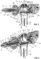
- FIG. 1 an embodiment of an inventive inlet fitting is shown.
- inlet fitting 1 is attached to a cistern 19.
- the inlet fitting a nut 20, with which the inlet fitting against the cistern 19 can be clamped.
- the inlet fitting 1 is used to fill the cistern 19 with rinse water.
- the rinse water from the cistern may then be supplied to a sanitary fitting such as a urinal or a toilet for flushing the same.
- the inlet fitting 1 comprises a housing 2, a water channel 3 arranged in the housing 2 with an inlet 4 and an outlet 5. Via the inlet 4 the inlet fitting 1 is connected to a water pipe. The outlet 5 protrudes into the cistern.
- a float-controlled valve 6 is arranged in the water guide channel 3, which blocks the water supply channel 3 and is free in the filling.
- the float-controlled valve 6 includes a float, not shown here, which controls the state of the float-controlled valve 6 based on the water level in the cistern 19. When the water level is lowered, the float-controlled valve 6 is open and with full cistern the float-controlled valve 6 is closed.
- the inlet 4 here comprises a threaded portion 21, via which the inlet fitting 1 can be connected to a water pipe.
- a nozzle body 22 is arranged in the region of the entrance. As seen from the inlet 4, the water flows via the inlet 4 to the nozzle body 22 and is then fed to the float-controlled valve 6.
- the inlet fitting 1 comprises an expansion element 7 arranged downstream of the float-controlled valve 6 as seen in the flow direction in the water channel 3.
- the expansion element 7 enlarges the cross-section of the water guide channel 3, so that an expansion of the water jet takes place and the flow velocity of the water jet is reduced. This expansion, together with the concomitant reduction in the flow rate, can reduce the noise when filling the cistern be reduced.
- the expansion element 7 may have various embodiments. Advantageous embodiments of the expansion element 7 but are designed such that the water jet can expand controlled in the water supply channel 3. This means that it is advantageous if the water jet is enlarged in a controlled manner in its enlargement, for example, by a corresponding guidance of the side walls of the water duct 3. Section, but this guide can also be interrupted, but it is then advantageous that this free water jet on a fluidic element impinges, which leads the water jet again.
- the expansion element 7 comprises a tube element 8 with a tube end 9 and a deflection element 10 with a deflection surface 11.
- the tube element 8 is directed with its tube end 9 onto the deflection surface 11.
- the pipe end 9 is spaced from the deflection surface 11.
- a water jet leaves the pipe element 8 in the region of its pipe end 9 when the valve 6 is open and then strikes the deflection surface 11 FIGS. 3 and 4 shown by the arrows with the reference symbol W accordingly.
- the tube element 8 has a tube beginning 23.
- the tube beginning 23 serves here as a valve seat for the float-controlled valve 6.
- a valve body 24 of the valve 6 projects into the tube beginning 23 inside.
- the sealing point between the pipe beginning 23 and the valve body 24 represents the closing member in the water supply channel 2 for the supply of the rinsing water.
- the movement of the valve body 24 is provided by a float, which is not shown in the figures.
- the pipe element 8 and also the deflection surface 11 are part of the water supply channel 3. In other words, these elements limit the water supply channel 3 towards the outside.
- the deflection surface 11 is shown in the embodiment according to the figures as a concave curved surface. In other embodiments, the deflection surface 11 may also be formed as a flat surface or as a convex surface. It would also be conceivable that the deflection surface 11 has the shape of a directed against the pipe end 9 cone.
- the deflection surface 11 according to the embodiment shown in the figures here has the shape of a screen.
- the deflection surface 11 extends from an intersection S of the central axis M8 of the tubular element 8 with the deflection surface 11 rounded to the tubular element 8.
- the center axis M8 defines the tube axis in the region of the tube end.
- the tubular element 8 is directed with its pipe end 9 to this intersection S.
- the radius of curvature of the rounding can be constant or variable.
- the radius of the deflection surface 11 is substantially constant and then merges into a cylindrical shape.
- the cylindrical shape or the cylindrical portion, which is formed by the cylindrical shape carries the reference numeral 25.
- the distance between pipe end 9 and the point of occurrence on the deflection surface 11 is preferably selected so that it is as small as possible. In preferred embodiments, the distance is a few millimeters. This means that the water jet is not guided over a comparatively short distance. Said center of the rounded deflection surface substantially corresponds to a vertex from which the deflection surface extends.
- the deflection surface 11 defines an interior space 12, in which the tubes E 9 protrudes.
- the pipe 8 protrudes with its pipe end 9 into the deflection element 10.
- the tube 8 is here between tube beginning 23 and tube end 9 with a 90 ° arc Mistake.
- the tube 8 extends over a first pipe section 29 to the tube beginning 23 below the deflection surface 11 to the level of the center thereof.
- the tube 9 extends with a second tube section 30 in the direction of the deflection surface 11, here into the deflection element 11.
- the first pipe section 29 is overflowed by the water after the deflection.
- the second pipe section 30 extends here along the central axis M8.
- annular gap 14 is formed between the outer side 13 of the tubular element 8 and the deflection surface 9, an annular gap 14 is formed.
- This annular gap 14 is flowed through by the rinsing water.
- the cross section of said annular gap 14 is preferably larger than the cross section of the tubular element 8.
- the inlet housing 1 preferably further comprises an outlet tube 15, which adjoins the expansion element 7.
- the outlet pipe 15 limits the water supply channel 3 on.
- the outlet pipe 15 ends with the outlet 5.
- the outlet pipe 15 is preferably vertical.
- the water in the water guide channel 3 is deflected by the deflection surface 11 into the outlet pipe 15.
- the rinse water flows through after the expansion of the water jet through the outlet pipe 15 and finally enters the cistern. This will be in the FIGS. 3 and 4 shown by the arrow Z.
- the medium axis M of the outlet pipe is collinear or parallel to the central axis M8 of the tubular element 8.
- the flow direction of the water is changed accordingly by the deflection element 10 with the deflection surface 11, so that the water flows in the installation position in the region of the tubular element 8 upwards and then through the deflection element 10 is deflected, wherein the water in the outlet pipe 15 then flows down.
- the deflection surface 11 extends in the region of the transition 16 between the deflection surface 11 and the outlet pipe 15, preferably matching the diameter of the outlet pipe 15. In other words, a fluidically good transition between the deflection surface 11 and the outlet pipe is ensured.
- the tubular element 8 with the first pipe section 29 projects laterally into the outlet pipe 15 and then extends upwards after the 90 ° bend. With the second pipe section 30, the pipe element 8 then runs parallel to the outlet pipe 15.
- the deflection element 10 closes in the present embodiment, the outlet tube 15 in the vertical direction as seen from above.
- the deflection element 10 thus forms a closure element for the outlet tube 15 with respect to the outlet 5.
- the inlet fitting 1 an air passage 17.
- This air passage 17 can be sucked at a negative pressure in the line, which is connected to the input 4, air from the cistern, so that prevents rinse water is sucked out of the cistern.
- This air passage 17 may be formed in various ways.
- the air passage 17 in the region of the transition 16 between the deflection element 10 and outlet pipe 15 is arranged.
- the air passage 17 is shown as part of the deflection element 10. It is a recess arranged in the deflection element 10, which then, when the deflection element 10 is in communication with the inlet fitting, provides a slot.
- the air passage 17 is behind a cover, wherein the cover objected to the air passage 17 and this covers with respect to the overflowing water.
- the air passage 17 may also have the shape of a narrow slit whose shorter clear width is overflowed by the rinse water.
- the deflection element 10 is shown as a separate part.
- the deflection element 10 may also be integrally formed on the housing 2.
- the deflection surface 11 in a particularly preferred embodiment has a flow divider or at least one flow divider 18.
- the flow dividers 18 extend away from the deflection surface 11. On the one hand, these two flow divider 18 serve the further expansion of the water jet. On the other hand, the water jet is divided in the desired direction. Preferably, in the FIG. 6 shown flow divider in installation position on the pipe section 29, which projects laterally into the outlet pipe 15.
- the expansion element 7 is a diffuser. An increase in diameter is likewise achieved via this diffuser, so that the flow velocity of the water decreases accordingly. All other elements of the inlet fitting 1 may be formed according to the first embodiment.
- the expansion element 7 comprises a diffuser and the deflection element 10 according to the first embodiment described above.
- the diffuser is preferably arranged in the flow direction before the deflection element 10. This allows a particularly quiet water flow can be achieved.
- the inlet fitting 1 preferably comprises a nozzle body 22.
- the nozzle body 22 is part of a nozzle 26, which comprises a nozzle channel 16.
- the nozzle channel 16 is influenced by the nozzle body 22.
- the nozzle 26 Seen in the direction of flow, the nozzle 26 is arranged in front of the float-controlled valve and in front of the expansion element 7.
- the water enters via the entrance 4 in the inlet fitting 1 and is guided by the water supply channel 3 accordingly.
- the water flows in the water guide channel 3, the nozzle 26.
- the water passes through the nozzle channel 27 therethrough.
- the water then leaves the nozzle channel 27 and is in an intermediate channel 28 around the outlet pipe 15 and through the outlet pipe 15 through to the float-controlled valve 6.
- the water is passed to the tube member 8 this through the pipe end. 9 leaves again in the direction of deflection element 10 or expansion element 7 and finally reaches the outlet tube 15.
Landscapes
- Engineering & Computer Science (AREA)
- General Engineering & Computer Science (AREA)
- Health & Medical Sciences (AREA)
- Public Health (AREA)
- Mechanical Engineering (AREA)
- Epidemiology (AREA)
- Life Sciences & Earth Sciences (AREA)
- Hydrology & Water Resources (AREA)
- Water Supply & Treatment (AREA)
- Sanitary Device For Flush Toilet (AREA)
- Nozzles (AREA)
Description
- Die vorliegende Erfindung betrifft eine Einlaufgarnitur für einen Spülkasten nach dem Oberbegriff von Anspruch 1.
- Einlaufgarnituren dienen der Befüllung von Spülkästen von Sanitärartikeln, wie Toiletten oder Urinalen. Beispielsweise ist aus der
EP 1 175 576 eine Einlaufgarnitur für einen Spülkasten bekannt geworden. Mit dieser Einlaufgarnitur wurden gute Ergebnisse bezüglich der Vermeidung von Fehlfunktionen erreicht. Auch bezüglich der Geräuschbildung sind die nach derEP 1 175 576 hergestellten Einlaufgarnituren vorteilhaft. Auch ist aus derWO 00/15991 - Es ist aber ein Bedürfnis, Einlaufgarnituren anzugeben, deren Geräuschbildung weiter reduziert wird, so dass der Benutzer die Befüllung nicht akustisch wahrnehmen kann.
- Der Erfindung liegt eine Aufgabe zugrunde, eine Einlaufgarnitur anzugeben, welche beim Durchfluss von Spülwasser möglichst geräuscharm ist.
- Diese Aufgabe löst der Gegenstand von Anspruch 1. Demgemäss umfasst eine Einlaufgarnitur für die Befüllung eines Spülkastens ein Gehäuse, ein im Gehäuse angeordneten Wasserführungskanal mit einem Eingang und einem Ausgang, und ein im Wasserführungskanal angeordnetes schwimmergesteuertes Ventil, welches den Wasserführungskanal sperrt bzw. bei der Befüllung frei gibt. Weiter ist im Wasserführungskanal in Fliessrichtung gesehen nach dem Ventil ein Expansionselement angeordnet, welches den Querschnitt des Wasserführungskanals vergössert, so dass eine Expansion des Wasserstrahls stattfindet und die Fliessgeschwindigkeit reduziert wird.
- Durch die Expansion des Wasserstrahls wird eine Verringerung der Fliessgeschwindigkeit erreicht, wodurch die Geräuschbildung in der Einlaufgarnitur ebenfalls verkleinert wird. Bei der Expansion des Wasserstrahls wird insbesondere dessen Hüllkurve, welche den Wasserstrahl umhüllt, verändert.
- Besonders bevorzugt ist das Expansionselement in Strömungsrichtung vor einem Auslassrohr, welches den Ausgang bildet, angeordnet. Durch diese Anordnung kann erreicht werden, dass der Wasserstrahl vor dem Ausgang verbreitert wird und dann durch das Auslassrohr geführt werden kann, wobei innerhalb des Auslassrohr es zu einer weiteren Strömungsberuhigung kommen kann. Durch das Auslassrohr ist das Spülwasser in einen Spülkasten abgebbar.
- In einer Weiterbildung der Erfindung umfasst das Expansionselement ein Rohrelement mit einem Rohrende und ein Umlenkungselement mit einer Umlenkungsfläche. Das Rohrelement ist mit seinem Rohrende auf die Umlenkungsfläche gerichtet, wobei das Rohrende beabstandet zur Umlenkungsfläche steht. Durch diesen Abstand trifft der Wasserstrahl als freier Wasserstrahl auf die Umlenkungsfläche auf und wird dort umgelenkt.
- Vorzugsweise sind das Rohrelement und die Umlenkungsfläche Teil des Wasserführungskanals bzw. begrenzen den Wasserführungskanal im entsprechenden Bereich.
- Die Umlenkungsfläche ist als gekrümmte Fläche ausgebildet. Das Rohrelement kann also auf eine gekrümmte oder eine ebene Fläche gerichtet sein, wobei das Rohrende in einem Abstand zur besagten Fläche liegt.
- Das Rohrelement kann in verschiedenen Richtungen auf die Umlenkungsfläche gerichtet sein. Besonders bevorzugt ist das Rohrelement mit der Mittelachse des Rohrs aber rechtwinklig auf die Fläche gerichtet.
- Nach der Erfindung erstreckt sich die Umlenkungsfläche von einem Schnittpunkt der Mittelachse des Rohrelementes gerundet zum Rohrelement hin. Das Rohrelement ist mit seinem Rohrende auf diesen Schnittpunkt gerichtet. Die Umlenkungsfläche bildet also eine Art Schirm bzw. weist im Querschnitt gesehen die Form einer Parabel auf, wobei der Wasserstrahl von Rohrende her kommend auf den Scheitelpunkt auftrifft.
- In einer Weiterbildung der Erfindung kann die Umlenkungsfläche auch kegelförmig ausgebildet sein, wobei die Spitze des Kegels in das Zentrum des Rohrendes gerichtet ist und sich von dort kegelförmig vom Rohrende weg erstreckt. Die Mantelfläche des Kegels kann mindestens bereichsweise, insbesondere gegenüber der Spitze gerundet ausgebildet sein. Die Rundung kann dabei die Fläche, welche durch die Parabel bereitgestellt wird, übergehen. Mit anderen Worten gesagt, kann die Umlenkungsfläche in der Querschnittsform der Parabel im Scheitelpunkt einen Kegel aufweisen, dessen Spitze gegen das Rohrende gerichtet ist. Der Übergang zwischen Kegelfläche und Parabelfläche ist vorzugsweise gerundet.
- Erfindungsgemäß definiert die Umlenkungsfläche einen Innenraum, in welchen das Rohrelement einragt, wobei zwischen der Aussenseite des Rohrelements und der Umlenkungsfläche ein ringförmiger Spalt vorhanden ist.
- Vorzugsweise ist der Querschnitt des besagten Spaltes grösser als der Querschnitt des Rohrelements. Besonders bevorzugt ist der Querschnitt des Spaltes auf den Leitungsdruck einstellbar oder selbstregulierend.
- Gegenüber dem Rohrende weist das Rohrelement ein Rohranfang auf, welcher vorzugsweise einen Teil des schwimmergesteuerten Ventils darstellt. Ein Ventilstössel des Schwimmergesteuerten Ventil ragt dabei in den Rohranfang ein bildet mit dem Rohranfang eine entsprechende Dichtstelle.
- Zwischen dem Rohranfang und dem Rohrende weist das Rohrelement in einer besonders bevorzugten Ausführungsform einen Rohrbogen auf, welcher vorzugsweise um 90° gebogen ist. Vorzugsweise verläuft das Rohrelement in Einbaulage gesehen mindestens teilweise unterhalb des Umlekungselementes. Besonders bevorzugt ragt das Rohrelement seitlich in ein Auslassrohr, welches ebenfalls einen Teil der Ablaufgranitur bzw. des Gehäuses darstellt.
- Vorzugsweise umfasst der Wasserführungskanal ein Auslassrohr, welches in Einbaulage Vertikal verläuft, wobei die Umlenkungsfläche das Wasser in das Auslassrohr umlenkt und wobei durch das Auslassrohr das Spülwasser in einen Spülkasten abgebbar ist.
- Besonders bevorzugt verläuft die Mittelachse des Auslassrohrs abschnittsweise kollinear oder parallel zur Mittelachse des Rohrelements. Vorzugsweise verläuft die Umlenkungsfläche im Bereich des Übergangs in das oder in Richtung des Auslassrohrs fluchtend zum Auslassrohr.
- In einer besonders bevorzugten Ausführung schliesst das Umlenkungselement das Auslassrohr in der Vertikalen gegen oben hin ab. Besonders bevorzugt weist das Umlenkungselement die Gestalt eines Deckels auf.
- Vorzuweise weisen das Umlenkungselement und/oder das Auslassrohr, insbesondere im Bereich des Übergangs zwischen Umlenkungselement und Auslassrohr, mindestens einen Luftdurchgang auf. Durch diesen Luftdurchgang kann im Falle eines Unterdruckes im Wasserführungsführungskanal über diesen Luftkanal Luft aus dem Spülkasten angesogen werden.
- Besonders bevorzugt liegt der Entlüftungsdurchgang hinter einer Abdeckung, wobei die Abdeckung beabstandet zum Entlüftungsdurchgang liegt und diesen bezüglich des überfliessenden Wassers überdeckt. Alternativ weist der Entlüftungsdurchgang in Fliessrichtung die Form eines schmalen Schlitzes auf, dessen kürzere lichte Weite vom Spülwasser überflossen wird.
- Besonders bevorzugt umfasst die Umlenkungsfläche mindestens einen Strömungsteiler, insbesondere in der Gestalt eines sich von der Umlenkungsfläche erstreckenden Kegels.
- In einer Weiterbildung ist das Expansionselement ein Diffusor.
- In einer Weiterbildung umfasst das Expansionselement einen Diffusor, welcher in Strömungsrichtung gesehen vor dem Umlenkungselement angeordnet ist. Es handelt sich hierbei um eine zweistufige Expansion des Wasserstrahls.
- Besonders bevorzugt umfasst der Wasserführungskanal vom Eingang her gesehen eine Düse mit einem Düsenkanal, wobei die Düse in Fliessrichtung gesehen vor dem schwimmergesteuerten Ventil und vor dem Expansionselement liegt.
- Eine Spülkastenanordnung umfasst vorzugsweise eine Einlaufgarnitur nach obiger Beschreibung.
- Weitere Ausführungsformen sind in den abhängigen Ansprüchen angegeben.
- Bevorzugte Ausführungsformen der Erfindung werden im Folgenden anhand der Zeichnungen beschrieben, die lediglich zur Erläuterung dienen und nicht einschränkend auszulegen sind. In den Zeichnungen zeigen:
- Fig. 1
- eine Schnittansicht durch eine Einlaufgarnitur gemäss einer Ausführungsform;
- Fig. 2
- eine perspektivische Ansicht der Schnittansicht nach
Figur 1 ; - Fig. 3
- die Schnittansicht nach
Figur 1 mit eingezeichneten Durchflusspfeilen; - Fig. 4
- die Schnittansicht nach
Figur 1 mit eingezeichneten Durchflusspfeilen; und - Fig. 5
- eine Detailansicht einer ersten Variante eines Umlenkungselementes der Einlaufgarnitur nach
Figur 1 ; und - Fig. 6
- eine Detailansicht einer zweiten Variante eines Umlenkungselementes der Einlaufgarnitur nach
Figur 1 . - In der
Figur 1 wird eine Ausführungsform einer erfindungsgemässen Einlaufgarnitur gezeigt. - Die in
Figur 1 gezeigte Einlaufgarnitur 1 wird an einem Spülkasten 19 befestigt. Hierfür weist die Einlaufgarnitur eine Mutter 20 auf, mit welcher die Einlaufgarnitur gegen den Spülkasten 19 geklemmt werden kann. Die Einlaufgarnitur 1 dient der Befüllung des Spülkastens 19 mit Spülwasser. Das Spülwasser aus dem Spülkasten kann dann einer Sanitärarmatur, wie beispielsweise einem Urinal oder einer Toilette zwecks Spülung derselben zugeführt werden. - Die Einlaufgarnitur 1 umfasst ein Gehäuse 2, einen im Gehäuse 2 angeordneten Wasserführungskanal 3 mit einem Eingang 4 und einem Ausgang 5. Über den Eingang 4 ist die Einlaufgarnitur 1 an einer Wasserleitung angeschlossen. Der Ausgang 5 ragt in den Spülkasten hinein. Weiter ist im Wasserführungskanal 3 ein schwimmergesteuertes Ventil 6 angeordnet, welches den Wasserführungskanal 3 sperrt bzw. bei der Befüllung frei gibt. Das schwimmergesteuerte Ventil 6 umfasst einen hier nicht dargestellten Schwimmer, welcher den Zustand des schwimmergesteuerten Ventils 6 anhand des Wasserstandes im Spülkasten 19 steuert. Bei abgesenktem Wasserstand ist das schwimmergesteuerte Ventil 6 offen und bei vollem Spülkasten ist das schwimmergesteuerte Ventil 6 geschlossen.
- Der Eingang 4 umfasst hier einen Gewindeabschnitt 21, über welchen die Einlaufgarnitur 1 mit einer Wasserleitung verbunden werden kann. Weiter ist im Bereich des Eingangs ein Düsenkörper 22 angeordnet. Das Wasser fliesst vom Eingang 4 her gesehen über den Eingang 4 zum Düsenkörper 22 und wird dann dem schwimmergesteuerten Ventil 6 zugeleitet.
- Weiter umfasst die Einlaufgarnitur 1 ein im Wasserkanal 3 in Fliessrichtung gesehen nach dem schwimmergesteuerten Ventil 6 angeordnetes Expansionselement 7. Das Expansionselement 7 vergrössert den Querschnitt des Wasserführungskanals 3, sodass eine Expansion des Wasserstrahls stattfindet und die Fliessgeschwindigkeit des Wasserstrahls reduziert wird. Durch diese Expansion gemeinsam mit der einhergehenden Reduktion der Fliessgeschwindigkeit kann die Geräuschbildung bei der Befüllung des Spülkastens reduziert werden.
- Das Expansionselement 7 kann verschiedene Ausführungsformen aufweisen. Vorteilhafte Ausführungsformen des Expansionselementes 7 sind aber derart ausgebildet, dass der Wasserstrahl im Wasserführungskanal 3 kontrolliert expandieren kann. Das heisst, dass es vorteilhaft ist, wenn der Wasserstrahl bei seiner Vergrösserung kontrolliert vergrössert wird, beispielsweise durch eine entsprechende Führung der Seitenwände des Wasserführungskanals 3. Abschnittsweise kann diese Führung aber auch unterbrochen sein, wobei es dann aber Vorteilhaft ist, dass dieser freie Wasserstrahl auf ein strömungstechnisches Element auftrifft, welches den Wasserstrahl wieder führt.
- In den
Figuren 1 bis 4 wird ein Expansionselement 7 gemäss einer ersten bevorzugten Ausführungsform gezeigt. Gemäss dieser ersten Ausführungsform umfasst das Expansionselement 7 ein Rohrelement 8 mit einem Rohrende 9 und ein Umlenkungselement 10 mit einer Umlenkungsfläche 11. Das Rohrelement 8 ist mit seinem Rohrende 9 auf die Umlenkungsfläche 11 gerichtet. Das Rohrende 9 steht beabstandet zur Umlenkungsfläche 11. Ein Wasserstrahl verlässt bei geöffnetem Ventil 6 das Rohrelement 8 im Bereich seines Rohrendes 9 und trifft dann auf die Umlenkungsfläche 11. Dies wird in denFiguren 3 und 4 durch die Pfeile mit dem Bezugszeichen W entsprechend gezeigt. - Beim Verlassen des Rohrelementes 8 über das Rohrende 9 platzt der Wasserstrahl W aufgrund des Wegfalls seines Führungselementes, nämlich dem Rohrelement 8, auf und wird durch die Umlenkungsfläche 11 entsprechend umgelenkt. Ja nach Ausbildung der Umlenkungsfläche kann eine sehr grosse Expansion des Wasserstrahls erreicht werden, wodurch die Fliessgeschwindigkeit massiv reduziert wird.
- Gegenüber dem Rohrende 9 weist das Rohrelement 8 einen Rohranfang 23 auf. Der Rohranfang 23 dient hier als Ventilsitz für das schwimmergesteuerte Ventil 6. Ein Ventilkörper 24 des Ventils 6 ragt in den Rohranfang 23 hinein. Die Dichtstelle zwischen Rohranfang 23 und Ventilkörper 24 stellt das Abschlussorgan im Wasserführungskanal 2 für die Zuführung des Spülwassers dar. Die Bewegung des Ventilkörpers 24 wird durch einen Schwimmer, der in den Figuren nicht gezeigt ist, bereitgestellt.
- Das Rohrelement 8 und auch die Umlenkungsfläche 11 sind Teil des Wasserführungskanals 3. Mit anderen Worten gesagt begrenzen diese Elemente den Wasserführungskanal 3 gegen aussen hin.
- Die Umlenkungsfläche 11 ist in der Ausführungsform gemäss den Figuren als konkav gekrümmte Fläche dargestellt. In anderen Ausführungsformen kann die Umlenkungsfläche 11 auch als ebene Fläche oder als konvexe Fläche ausgebildet sein. Auch wäre es denkbar, dass die Umlenkungsfläche 11 die Form eines gegen das Rohrende 9 gerichteten Kegels aufweist.
- Die Umlenkungsfläche 11 gemäss der in den Figuren gezeigten Ausführungsform hat hier die Form eines Schirms. Die Umlenkungsfläche 11 erstreckt sich von einem Schnittpunkt S der Mittelachse M8 des Rohrelementes 8 mit der Umlenkungsfläche 11 gerundet zum Rohrelement 8 hin. Die Mittelachse M8 definiert die Rohrachse im Bereich des Rohrendes. Das Rohrelement 8 ist mit seinem Rohrende 9 auf diesen Schnittpunkt S gerichtet. Der Krümmungsradius der Rundung kann konstant oder variabel sein. Im vorliegenden Ausführungsbeispiel ist der Radius der Umlenkungsfläche 11 im Wesentlichen konstant und geht dann in eine zylindrische Form über. Die zylindrische Form bzw. der zylindrische Abschnitt, welcher durch die zylindrische Form gebildet wird trägt das Bezugszeichen 25.
- Zwischen dem Rohrende 9 und dem Zentrum der gerundeten Umlenkungsfläche 11 ist der Wasserstrahl frei. Die Distanz zwischen Rohrende 9 und dem Auftrittspunkt auf der Umlenkungsfläche 11 ist vorzugsweise so gewählt, dass diese möglichst klein ist. In bevorzugten Ausführungsformen beträgt die Distanz wenige Millimeter. Das heisst, dass der Wasserstrahl nur über eine vergleichsweise kurze Distanz nicht geführt ist. Das besagte Zentrum der gerundeten Umlenkungsfläche entspricht im Wesentlichen einem Scheitelpunkt, von welchem sich die Umlenkungsfläche erstreckt.
- Die Umlenkungsfläche 11 definiert einen Innenraum 12, in welchen das Rohrenede 9 hineinragt. Mit anderen Worten gesagt ragt das Rohr 8 mit seinem Rohrende 9 in das Umlenkungselement 10 hinein.
- Das Rohr 8 ist hier zwischen Rohranfang 23 und Rohrende 9 mit einem 90° Bogen versehen. Das Rohr 8 verläuft über einen ersten Rohrabschnitt 29 nach dem Rohranfang 23 unterhalb der Umlenkungsfläche 11 bis auf die Höhe des Zentrums derselben. Anschliessend nach dem 90° Bogen verläuft das Rohr 9 mit einem zweiten Rohrabschnitt 30 in Richtung Umlenkungsfläche 11, hier in das Umlenkungselement 11 hinein. Der erste Rohrabschnitt 29 wird durch das Wasser nach erfolgter Umlenkung überströmt. Der zweite Rohrabschnitt 30 verläuft hier entlang der Mittelachse M8.
- Zwischen der Aussenseite 13 des Rohrelementes 8 und der Umlenkungsfläche 9 entsteht ein ringförmiger Spalt 14. Dieser ringförmige Spalt 14 wird durch das Spülwasser durchströmt. Der Querschnitt des besagten ringförmigen Spaltes 14 ist vorzugsweise grösser als der Querschnitt des Rohrelementes 8.
- Wie in den
Figuren 1 bis 4 gezeigt umfasst das Einlaufgehäuse 1 vorzugsweise weiter ein Auslassrohr 15, welches sich dem Expansionselement 7 anschliesst. Das Auslassrohr 15 begrenzt dabei den Wasserführungskanal 3 weiter. Das Auslassrohr 15 endet mit dem Ausgang 5. In Einbaulage steht das Auslassrohr 15 vorzugsweise vertikal. In der vorliegenden Ausführungsform wird das Wasser im Wasserführungskanal 3 durch die Umlenkungsfläche 11 in das Auslassrohr 15 umgelenkt. Das Spülwasser durchfliesst nach erfolgter Expansion des Wasserstrahls durch das Auslassrohr 15 und gelangt schliesslich in den Spülkasten. Dies wird in denFiguren 3 und 4 durch den Pfeil Z gezeigt. - Die Mittelachse M des Auslassrohrs verläuft kollinear oder parallel zur Mittelachse M8 des Rohrelementes 8. Die Fliessrichtung des Wassers wird durch das Umlenkungselement 10 mit der Umlenkungsfläche 11 entsprechend geändert, so dass das Wasser im Bereich des Rohrelementes 8 in Einbaulage gesehen nach oben fliesst und dann durch das Umlenkungselement 10 umgelenkt wird, wobei das Wasser im Auslassrohr 15 dann nach unten fliesst.
- Die Umlenkungsfläche 11 verläuft im Bereich des Übergangs 16 zwischen Umlenkungsfläche 11 und Auslassrohr 15 vorzugsweise passend zum Durchmesser des Auslassrohrs 15. Mit anderen Worten gesagt ist ein strömungstechnisch guter Übergang zwischen der Umlenkungsfläche 11 und dem Auslassrohr gewährleistet.
- Das Rohrelement 8 mit dem ersten Rohrabschnitt 29 ragt seitlich in das Auslassrohr 15 hinein und erstreckt sich dann nach dem 90°-Bogen nach oben. Mit dem zweiten Rohrabschnitt 30 verläuft das Rohrelement 8 dann parallel zum Auslassrohr 15.
- Das Umlenkungselement 10 schliesst in der vorliegenden Ausführungsform das Auslassrohr 15 in der Vertikalen gesehen gegen oben hin ab. Das Umlenkungselement 10 bildet also ein Verschlusselement für das Auslassrohr 15 gegenüber des Ausgangs 5.
- Besonders bevorzugt weist die Einlaufgarnitur 1 einen Luftdurchgang 17 auf. Über diesen Luftdurchgang 17 kann bei einem Unterdruck in der Leitung, die am Eingang 4 angeschlossen ist, Luft aus dem Spülkasten angesogen werden, sodass verhindert wird, dass Spülwasser aus dem Spülkasten angesogen wird. Dieser Luftdurchgang 17 kann verschiedenartig ausgebildet sein.
- In der vorliegenden Ausführungsform ist der Luftdurchgang 17 im Bereich des Übergangs 16 zwischen Umlenkungselement 10 und Auslassrohr 15 angeordnet. In den
Figuren 5 und 6 wird der Luftdurchgang 17 als Teil des Umlenkungselementes 10 dargestellt. Es handelt sich dabei um eine im Umlenkungselement 10 angeordnete Ausnehmung, welche dann, wenn das Umlenkungselement 10 mit der Einlaufgarnitur in Verbindung steht, einen Schlitz bereitstellt. - In einer anderen Variante liegt der Luftdurchgang 17 hinter einer Abdeckung, wobei die Abdeckung beanstandet zum Luftdurchgang 17 liegt und diesen bezüglich des überfliessenden Wassers überdeckt. Somit kann bei der Befüllung des Spülkastens kein Wasser durch den Luftdurchgang 17 hindurchtreten. Der Luftdurchgang 17 kann aber auch die Form eines schmalen Schlitzes aufweisen, dessen kürzere lichte Weite vom Spülwasser überflossen wird.
- In den
Figuren 5 und 6 wird das Umlenkungselement 10 als separates Teil dargestellt. Das Umlenkungselement 10 kann aber auch einstückig am Gehäuse 2 angeformt sein. - In der
Figur 6 wird gezeigt, dass die Umlenkungsfläche 11 in einer besonders bevorzugten Ausführung einen Strömungsteiler bzw. mindestens einen Strömungsteiler 18 aufweist. - Die Strömungsteiler 18 erstrecken sich von der Umlenkungsfläche 11 weg. Einerseits dienen diese beiden Strömungsteiler 18 der weiteren Expansion des Wasserstrahls. Andererseits wird der Wasserstrahl in die gewünschte Richtung geteilt. Vorzugsweise liegen die in der
Figur 6 gezeigten Strömungsteiler in Einbaulage über den Rohrabschnitt 29, welcher seitlich in das Auslassrohr 15 hineinragt. - In einer weiteren, hier nicht dargestellten Ausführungsform wäre es zudem denkbar, dass es sich von der Umlenkungsfläche 11 ein Strömungsteiler 18 in der Form eines Kegels in Richtung des Rohrelementes 8 erstreckt.
- In einer zweiten, hier nicht gezeigten Ausführungsform, ist das Expansionselement 7 ein Diffusor. Über diesen Diffusor wird dabei ebenfalls eine Durchmesservergrösserung erreicht, sodass die Fliessgeschwindigkeit des Wassers entsprechend abnimmt. Alle anderen Elemente der Einlaufgarnitur 1 können gemäss der ersten Ausführungsform ausgebildet sein.
- In einer dritten Ausführungsform, welche ebenfalls nicht in den Figuren gezeigt ist, umfasst das Expansionselement 7 einen Diffusor und dass Umlenkungselement 10 gemäss der oben beschriebenen ersten Ausführungsform. Der Diffusor ist dabei vorzugsweise in Strömungsrichtung gesehen vor dem Umlenkungselement 10 angeordnet. Hierdurch kann eine besonders leise Wasserführung erreicht werden.
- Wie oben bereits erwähnt umfasst die Einlaufgarnitur 1 gemäss aller Ausführungsform vorzugsweise einen Düsenkörper 22. Der Düsenkörper 22 ist dabei Teil einer Düse 26, die einen Düsenkanal 16 umfasst. Der Düsenkanal 16 wird dabei durch den Düsenkörper 22 beeinflusst. In Fliessrichtung gesehen ist die Düse 26 vor dem schwimmergesteuerten Ventil und vor den Expansionselement 7 angeordnet.
- Unter Bezugnahme auf die
Figuren 3 und 4 wird nun nochmals der Wasserfluss in der Einlaufgarnitur 1 erläutert. Das Wasser tritt über den Eingang 4 in die Einlaufgarnitur 1 ein und wird vom Wasserführungskanal 3 entsprechend geführt. In einem ersten Abschnitt fliesst das Wasser im Wasserführungskanal 3 die Düse 26. Dabei tritt das Wasser durch den Düsenkanal 27 hindurch. Das Wasser verlässt dann den Düsenkanal 27 und wird in einem Zwischenkanal 28 um das Auslassrohr 15 herum bzw. durch das Auslassrohr 15 hindurch zum schwimmergesteuerten Ventil 6. Nach Passieren des schwimmergesteuerten Ventils 6 wird das Wasser zum Rohrelement 8 geführt wobei es dieses durch das Rohrende 9 in Richtung Umlenkungselement 10 bzw. Expansionselement 7 wieder verlässt und schliesslich zum Auslassrohr 15 gelangt. -
1 Einlaufgarnitur 29 erster Rohrabschnitt 2 Gehäuse 30 zweiter Rohrabschnitt 3 Wasserführungskanal S Schnittpunkt 4 Eingang M Mittelachse 5 Ausgang M8 Mittelachse 6 schwimmergesteuertes Ventil 7 Expansionselement 8 Rohrelement 9 Rohrende 10 Umlenkungselement 11 Umlenkungsfläche 12 Innenraum 13 Aussenseite 14 Spalt 15 Auslassrohr 16 Übergang 17 Luftdurchgang 18 Strömungsteiler 19 Spülkasten 20 Mutter 21 Gewindeabschnitt 22 Düsenkörper 23 Rohranfang 24 Ventilkörper 25 zylindrische Form 26 Düse 27 Düsenkanal 28 Zwischenkanal
Claims (12)
- Einlaufgarnitur (1) für die Befüllung eines Spülkastens umfassend ein Gehäuse (2),
ein im Gehäuse (2) angeordneten Wasserführungskanal (3) mit einem Eingang (4) und einem Ausgang (5),
ein im Wasserführungskanal (3) angeordnetes schwimmergesteuertes Ventil (6), welches den Wasserführungskanal (3) sperrt bzw. bei der Befüllung frei gibt,
wobei im Wasserführungskanal (3) in Fliessrichtung gesehen nach dem Ventil (6) ein Expansionselement (7) angeordnet ist, welches den Querschnitt des Wasserführungskanals (3) vergrössert, so dass eine Expansion des Wasserstrahls stattfindet und die Fliessgeschwindigkeit reduziert wird,
wobei das Expansionselement (7) ein Rohrelement (8) mit einem Rohrende (9) und ein Umlenkungselement (10) mit einer Umlenkungsfläche (11) umfasst, wobei das Rohrelement (8) mit seinem Rohrende (9) auf die Umlenkungsfläche (11) gerichtet ist und wobei das Rohrende (9) beabstandet zur Umlenkungsfläche (11) angeordnet ist, dadurch gekennzeichnet,
dass die Umlenkungsfläche (11) als gekrümmte Fläche ausgebildet ist,
dass sich die Umlenkungsfläche (11) von einem Schnittpunkt (S) der Mittelachse (M) des Rohrelementes (8) gerundet zum Rohrelement (8) hin erstreckt, und wobei das Rohrelement (8) mit seinem Rohrende (9) auf diesen Schnittpunkt (S) bzw. auf die Umlenkungsfläche (11) gerichtet ist,
dass die Umlenkungsfläche (11) einen Innenraum (12) definiert, in welchen das Rohrelement (8) einragt, und
dass zwischen der Aussenseite (13) des Rohrelements (8) und der Umlenkungsfläche (11) ein ringförmiger Spalt (14) vorhanden ist. - Einlaufgarnitur nach Anspruch 1, dadurch gekennzeichnet, dass das Rohrelement (8) und die Umlenkungsfläche (11) Teil des Wasserführungskanals (3) sind.
- Einlaufgarnitur nach einem der vorhergehenden Ansprüche, dadurch gekennzeichnet, dass der Querschnitt des besagten Spaltes (14) grösser ist als der Querschnitt des Rohrelements (8).
- Einlaufgarnitur nach einem der vorhergehenden Ansprüche, dadurch gekennzeichnet, dass der Wasserführungskanal (3) ein Auslassrohr (15) umfasst, welches in Einbaulage Vertikal verläuft, wobei die Umlenkungsfläche (11) das Wasser in das oder in Richtung des Auslassrohr (15) umlenkt und wobei durch das Auslassrohr (15) das Spülwasser in einen Spülkasten abgebbar ist.
- Einlaufgarnitur nach Anspruch 4, dadurch gekennzeichnet, dass die Mittelachse des Auslassrohrs (15) abschnittsweise kollinear oder parallel zur Mittelachse des Rohrelements (8) verläuft
und/oder dass die Umlenkungsfläche (11) im Bereich des Übergangs (16) in das Auslassrohr (15) fluchtend zum Auslassrohr (15) verläuft
und/oder dass sich das Auslassrohr (15) in Fliessrichtung des Spülwassers gesehen dem Umlenkungselement (10) anschliesst, vorzugsweise unmittelbar anschliesst,
und/oder dass das Umlenkungselement (10) Teil des Auslassrohrs (15) ist. - Einlaufgarnitur nach einem der Ansprüche 4 bis 5, dadurch gekennzeichnet, dass das Umlenkungselement (10) das Auslassrohr (15) in der Vertikalen gegen oben hin abschliesst.
- Einlaufgarnitur nach einem der vorhergehenden Ansprüche, dadurch gekennzeichnet, dass das Umlenkungselement (10) und/oder das Auslassrohr (15), insbesondere im Bereich des Übergangs (16) zwischen Umlenkungselement (10) und Auslassrohr (15), mindestens ein Luftdurchgang (17) aufweisen.
- Einlaufgarnitur nach Anspruch 7, dadurch gekennzeichnet, dass der Luftdurchgang (17) hinter einer Abdeckung liegt, wobei die Abdeckung beabstandet zum Luftdurchgang (17) liegt und diesen bezüglich des überfliessenden Wassers überdeckt oder dass der Luftdurchgang (17) in Fliessrichtung die Form eines schmalen Schlitzes aufweist, dessen kürzere lichte Weite vom Spülwasser überflossen wird.
- Einlaufgarnitur nach einem der vorhergehenden Ansprüche, dadurch gekennzeichnet, dass die Umlenkungsfläche (11) mindestens einen Strömungsteiler (18), insbesondere in der Gestalt eines sich von der Umlenkungsfläche (11) erstreckenden Kegels oder Keils, umfasst.
- Einlaufgarnitur nach einem der vorhergehenden Ansprüche, dadurch gekennzeichnet, dass das Expansionselement ein Diffusor ist.
- Einlaufgarnitur nach einem der vorhergehenden Ansprüche, dadurch gekennzeichnet, dass das Expansionselement einen Diffusor umfasst, welcher in Strömungsrichtung gesehen vor dem Umlenkungselement (10) angeordnet ist.
- Einlaufgarnitur nach einem der vorhergehenden Ansprüche, dadurch gekennzeichnet, dass der Wasserführungskanal (3) vom Eingang her gesehen eine Düse (15) mit einem Düsenkanal (16) umfasst, wobei die Düse in Fliessrichtung gesehen vor dem schwimmergesteuerten Ventil und vor dem Expansionselement liegt.
Priority Applications (3)
| Application Number | Priority Date | Filing Date | Title |
|---|---|---|---|
| PT131778219T PT2829666E (pt) | 2013-07-24 | 2013-07-24 | Válvula de entrada para um autoclismo |
| EP13177821.9A EP2829666B1 (de) | 2013-07-24 | 2013-07-24 | Einlaufgarnitur für einen Spülkasten |
| ES13177821.9T ES2573631T3 (es) | 2013-07-24 | 2013-07-24 | Grifería de entrada para una cisterna |
Applications Claiming Priority (1)
| Application Number | Priority Date | Filing Date | Title |
|---|---|---|---|
| EP13177821.9A EP2829666B1 (de) | 2013-07-24 | 2013-07-24 | Einlaufgarnitur für einen Spülkasten |
Publications (2)
| Publication Number | Publication Date |
|---|---|
| EP2829666A1 EP2829666A1 (de) | 2015-01-28 |
| EP2829666B1 true EP2829666B1 (de) | 2016-04-13 |
Family
ID=48875563
Family Applications (1)
| Application Number | Title | Priority Date | Filing Date |
|---|---|---|---|
| EP13177821.9A Active EP2829666B1 (de) | 2013-07-24 | 2013-07-24 | Einlaufgarnitur für einen Spülkasten |
Country Status (3)
| Country | Link |
|---|---|
| EP (1) | EP2829666B1 (de) |
| ES (1) | ES2573631T3 (de) |
| PT (1) | PT2829666E (de) |
Families Citing this family (3)
| Publication number | Priority date | Publication date | Assignee | Title |
|---|---|---|---|---|
| EP3263781B1 (de) * | 2016-07-01 | 2020-09-23 | Geberit International AG | Einlaufgarnitur |
| GB2573818B (en) * | 2018-05-18 | 2022-07-13 | Fluidmaster Gb Ltd | A Fluid Valve Assembly For a Water Storage Tank |
| IT201900014145A1 (it) * | 2019-08-06 | 2021-02-06 | Oli Sist Sanitarios S A | Dispositivo di alimentazione per una cassetta di risciacquo |
Family Cites Families (5)
| Publication number | Priority date | Publication date | Assignee | Title |
|---|---|---|---|---|
| DE1609275A1 (de) * | 1965-02-18 | 1970-02-12 | Schenk Emil | Schwimmergesteuertes Fuellventil fuer Klosettspuelkasten und sonstige Fluessigkeitsbehaelter |
| FR2724958B1 (fr) * | 1994-09-26 | 1996-12-27 | Ragot Claude | Installation de distribution d'eau pour reservoir de chasse de toilettes sanitaires |
| US6354326B1 (en) * | 1998-09-14 | 2002-03-12 | Fluidmaster, Inc. | Toilet fill valve with improved noise abatement |
| DE50002844D1 (de) | 1999-05-11 | 2003-08-14 | Geberit Technik Ag | Einlaufgarnitur für einen spülkasten |
| CN102466045B (zh) * | 2010-11-11 | 2013-11-06 | 李飞宇 | 一种马桶进水阀及其控制方法 |
-
2013
- 2013-07-24 PT PT131778219T patent/PT2829666E/pt unknown
- 2013-07-24 ES ES13177821.9T patent/ES2573631T3/es active Active
- 2013-07-24 EP EP13177821.9A patent/EP2829666B1/de active Active
Also Published As
| Publication number | Publication date |
|---|---|
| PT2829666E (pt) | 2016-06-16 |
| EP2829666A1 (de) | 2015-01-28 |
| ES2573631T3 (es) | 2016-06-09 |
Similar Documents
| Publication | Publication Date | Title |
|---|---|---|
| EP0622122B1 (de) | Flotationszelle mit einem Injektor | |
| DE8133875U1 (de) | "strahlregler zum anschluss an sanitaer-armaturen o.dgl." | |
| EP3510204B1 (de) | Sanitäre einsetzeinheit | |
| EP2840191A1 (de) | Geruchsverschlussvorrichtung | |
| EP3469158B1 (de) | Ablaufventil | |
| DE102007009717B4 (de) | Durchflussmengenregler | |
| EP2829666B1 (de) | Einlaufgarnitur für einen Spülkasten | |
| EP3453805A1 (de) | Spülwasserverteiler | |
| EP3935228B1 (de) | Strahlregler zur erzeugung eines belüfteten flüssigkeitsstrahls | |
| EP2871294B1 (de) | Einlaufgarnitur für einen Spülkasten | |
| EP1854926B1 (de) | Ablaufgarnitur für einen Spülkasten | |
| EP2765249B1 (de) | Ablaufgarnitur für einen Spülkasten | |
| DE102009011345A1 (de) | Strahlregler | |
| EP3263782B1 (de) | Einlaufgarnitur | |
| EP2700759A1 (de) | Einlaufgarnitur für einen Spülkasten | |
| DE102016010842B4 (de) | Sanitäre Einsetzeinheit | |
| EP1175576B1 (de) | Einlaufgarnitur für einen spülkasten | |
| EP3825479A1 (de) | Spülwasserverteiler | |
| EP4015720B1 (de) | Sanitäre armatur | |
| DE202019102916U1 (de) | Füllventil für einen Toiletten- oder Urinal-Spülkasten | |
| WO2015165591A1 (de) | Strahlregler | |
| EP4116511A1 (de) | Füllventil | |
| EP1327604B1 (de) | Zapfventil für Kraftstoff | |
| CH716366B1 (de) | Spülwasserverteiler für einen Sanitärartikel. | |
| EP4116512B1 (de) | Füllventil |
Legal Events
| Date | Code | Title | Description |
|---|---|---|---|
| 17P | Request for examination filed |
Effective date: 20130724 |
|
| AK | Designated contracting states |
Kind code of ref document: A1 Designated state(s): AL AT BE BG CH CY CZ DE DK EE ES FI FR GB GR HR HU IE IS IT LI LT LU LV MC MK MT NL NO PL PT RO RS SE SI SK SM TR |
|
| AX | Request for extension of the european patent |
Extension state: BA ME |
|
| PUAI | Public reference made under article 153(3) epc to a published international application that has entered the european phase |
Free format text: ORIGINAL CODE: 0009012 |
|
| R17P | Request for examination filed (corrected) |
Effective date: 20150623 |
|
| RBV | Designated contracting states (corrected) |
Designated state(s): AL AT BE BG CH CY CZ DE DK EE ES FI FR GB GR HR HU IE IS IT LI LT LU LV MC MK MT NL NO PL PT RO RS SE SI SK SM TR |
|
| REG | Reference to a national code |
Ref country code: DE Ref legal event code: R079 Ref document number: 502013002546 Country of ref document: DE Free format text: PREVIOUS MAIN CLASS: E03D0001320000 Ipc: F16K0047020000 |
|
| RIC1 | Information provided on ipc code assigned before grant |
Ipc: F16K 47/02 20060101AFI20150903BHEP Ipc: E03D 9/14 20060101ALI20150903BHEP Ipc: F16K 31/34 20060101ALI20150903BHEP Ipc: E03D 1/32 20060101ALI20150903BHEP |
|
| GRAP | Despatch of communication of intention to grant a patent |
Free format text: ORIGINAL CODE: EPIDOSNIGR1 |
|
| INTG | Intention to grant announced |
Effective date: 20151013 |
|
| GRAS | Grant fee paid |
Free format text: ORIGINAL CODE: EPIDOSNIGR3 |
|
| GRAA | (expected) grant |
Free format text: ORIGINAL CODE: 0009210 |
|
| AK | Designated contracting states |
Kind code of ref document: B1 Designated state(s): AL AT BE BG CH CY CZ DE DK EE ES FI FR GB GR HR HU IE IS IT LI LT LU LV MC MK MT NL NO PL PT RO RS SE SI SK SM TR |
|
| REG | Reference to a national code |
Ref country code: GB Ref legal event code: FG4D Free format text: NOT ENGLISH |
|
| REG | Reference to a national code |
Ref country code: AT Ref legal event code: REF Ref document number: 790519 Country of ref document: AT Kind code of ref document: T Effective date: 20160415 Ref country code: CH Ref legal event code: EP |
|
| REG | Reference to a national code |
Ref country code: IE Ref legal event code: FG4D Free format text: LANGUAGE OF EP DOCUMENT: GERMAN |
|
| REG | Reference to a national code |
Ref country code: DE Ref legal event code: R096 Ref document number: 502013002546 Country of ref document: DE |
|
| REG | Reference to a national code |
Ref country code: CH Ref legal event code: NV Representative=s name: ISLER AND PEDRAZZINI AG, CH |
|
| REG | Reference to a national code |
Ref country code: ES Ref legal event code: FG2A Ref document number: 2573631 Country of ref document: ES Kind code of ref document: T3 Effective date: 20160609 |
|
| REG | Reference to a national code |
Ref country code: PT Ref legal event code: SC4A Free format text: AVAILABILITY OF NATIONAL TRANSLATION Effective date: 20160608 |
|
| REG | Reference to a national code |
Ref country code: FR Ref legal event code: PLFP Year of fee payment: 4 |
|
| REG | Reference to a national code |
Ref country code: LT Ref legal event code: MG4D |
|
| REG | Reference to a national code |
Ref country code: NO Ref legal event code: T2 Effective date: 20160413 |
|
| REG | Reference to a national code |
Ref country code: NL Ref legal event code: MP Effective date: 20160413 |
|
| PG25 | Lapsed in a contracting state [announced via postgrant information from national office to epo] |
Ref country code: NL Free format text: LAPSE BECAUSE OF FAILURE TO SUBMIT A TRANSLATION OF THE DESCRIPTION OR TO PAY THE FEE WITHIN THE PRESCRIBED TIME-LIMIT Effective date: 20160413 Ref country code: LT Free format text: LAPSE BECAUSE OF FAILURE TO SUBMIT A TRANSLATION OF THE DESCRIPTION OR TO PAY THE FEE WITHIN THE PRESCRIBED TIME-LIMIT Effective date: 20160413 Ref country code: FI Free format text: LAPSE BECAUSE OF FAILURE TO SUBMIT A TRANSLATION OF THE DESCRIPTION OR TO PAY THE FEE WITHIN THE PRESCRIBED TIME-LIMIT Effective date: 20160413 Ref country code: PL Free format text: LAPSE BECAUSE OF FAILURE TO SUBMIT A TRANSLATION OF THE DESCRIPTION OR TO PAY THE FEE WITHIN THE PRESCRIBED TIME-LIMIT Effective date: 20160413 |
|
| PG25 | Lapsed in a contracting state [announced via postgrant information from national office to epo] |
Ref country code: RS Free format text: LAPSE BECAUSE OF FAILURE TO SUBMIT A TRANSLATION OF THE DESCRIPTION OR TO PAY THE FEE WITHIN THE PRESCRIBED TIME-LIMIT Effective date: 20160413 Ref country code: HR Free format text: LAPSE BECAUSE OF FAILURE TO SUBMIT A TRANSLATION OF THE DESCRIPTION OR TO PAY THE FEE WITHIN THE PRESCRIBED TIME-LIMIT Effective date: 20160413 Ref country code: LV Free format text: LAPSE BECAUSE OF FAILURE TO SUBMIT A TRANSLATION OF THE DESCRIPTION OR TO PAY THE FEE WITHIN THE PRESCRIBED TIME-LIMIT Effective date: 20160413 Ref country code: SE Free format text: LAPSE BECAUSE OF FAILURE TO SUBMIT A TRANSLATION OF THE DESCRIPTION OR TO PAY THE FEE WITHIN THE PRESCRIBED TIME-LIMIT Effective date: 20160413 Ref country code: GR Free format text: LAPSE BECAUSE OF FAILURE TO SUBMIT A TRANSLATION OF THE DESCRIPTION OR TO PAY THE FEE WITHIN THE PRESCRIBED TIME-LIMIT Effective date: 20160714 |
|
| PG25 | Lapsed in a contracting state [announced via postgrant information from national office to epo] |
Ref country code: BE Free format text: LAPSE BECAUSE OF NON-PAYMENT OF DUE FEES Effective date: 20160731 |
|
| REG | Reference to a national code |
Ref country code: DE Ref legal event code: R097 Ref document number: 502013002546 Country of ref document: DE |
|
| PG25 | Lapsed in a contracting state [announced via postgrant information from national office to epo] |
Ref country code: DK Free format text: LAPSE BECAUSE OF FAILURE TO SUBMIT A TRANSLATION OF THE DESCRIPTION OR TO PAY THE FEE WITHIN THE PRESCRIBED TIME-LIMIT Effective date: 20160413 Ref country code: SK Free format text: LAPSE BECAUSE OF FAILURE TO SUBMIT A TRANSLATION OF THE DESCRIPTION OR TO PAY THE FEE WITHIN THE PRESCRIBED TIME-LIMIT Effective date: 20160413 Ref country code: CZ Free format text: LAPSE BECAUSE OF FAILURE TO SUBMIT A TRANSLATION OF THE DESCRIPTION OR TO PAY THE FEE WITHIN THE PRESCRIBED TIME-LIMIT Effective date: 20160413 Ref country code: EE Free format text: LAPSE BECAUSE OF FAILURE TO SUBMIT A TRANSLATION OF THE DESCRIPTION OR TO PAY THE FEE WITHIN THE PRESCRIBED TIME-LIMIT Effective date: 20160413 Ref country code: RO Free format text: LAPSE BECAUSE OF FAILURE TO SUBMIT A TRANSLATION OF THE DESCRIPTION OR TO PAY THE FEE WITHIN THE PRESCRIBED TIME-LIMIT Effective date: 20160413 |
|
| PLBE | No opposition filed within time limit |
Free format text: ORIGINAL CODE: 0009261 |
|
| STAA | Information on the status of an ep patent application or granted ep patent |
Free format text: STATUS: NO OPPOSITION FILED WITHIN TIME LIMIT |
|
| PG25 | Lapsed in a contracting state [announced via postgrant information from national office to epo] |
Ref country code: SM Free format text: LAPSE BECAUSE OF FAILURE TO SUBMIT A TRANSLATION OF THE DESCRIPTION OR TO PAY THE FEE WITHIN THE PRESCRIBED TIME-LIMIT Effective date: 20160413 |
|
| 26N | No opposition filed |
Effective date: 20170116 |
|
| PG25 | Lapsed in a contracting state [announced via postgrant information from national office to epo] |
Ref country code: MC Free format text: LAPSE BECAUSE OF FAILURE TO SUBMIT A TRANSLATION OF THE DESCRIPTION OR TO PAY THE FEE WITHIN THE PRESCRIBED TIME-LIMIT Effective date: 20160413 |
|
| REG | Reference to a national code |
Ref country code: IE Ref legal event code: MM4A |
|
| PG25 | Lapsed in a contracting state [announced via postgrant information from national office to epo] |
Ref country code: SI Free format text: LAPSE BECAUSE OF FAILURE TO SUBMIT A TRANSLATION OF THE DESCRIPTION OR TO PAY THE FEE WITHIN THE PRESCRIBED TIME-LIMIT Effective date: 20160413 |
|
| REG | Reference to a national code |
Ref country code: FR Ref legal event code: PLFP Year of fee payment: 5 |
|
| PG25 | Lapsed in a contracting state [announced via postgrant information from national office to epo] |
Ref country code: IE Free format text: LAPSE BECAUSE OF NON-PAYMENT OF DUE FEES Effective date: 20160724 |
|
| PG25 | Lapsed in a contracting state [announced via postgrant information from national office to epo] |
Ref country code: LU Free format text: LAPSE BECAUSE OF NON-PAYMENT OF DUE FEES Effective date: 20160724 |
|
| PG25 | Lapsed in a contracting state [announced via postgrant information from national office to epo] |
Ref country code: HU Free format text: LAPSE BECAUSE OF FAILURE TO SUBMIT A TRANSLATION OF THE DESCRIPTION OR TO PAY THE FEE WITHIN THE PRESCRIBED TIME-LIMIT; INVALID AB INITIO Effective date: 20130724 |
|
| PG25 | Lapsed in a contracting state [announced via postgrant information from national office to epo] |
Ref country code: MT Free format text: LAPSE BECAUSE OF FAILURE TO SUBMIT A TRANSLATION OF THE DESCRIPTION OR TO PAY THE FEE WITHIN THE PRESCRIBED TIME-LIMIT Effective date: 20160413 Ref country code: IS Free format text: LAPSE BECAUSE OF FAILURE TO SUBMIT A TRANSLATION OF THE DESCRIPTION OR TO PAY THE FEE WITHIN THE PRESCRIBED TIME-LIMIT Effective date: 20160413 Ref country code: CY Free format text: LAPSE BECAUSE OF FAILURE TO SUBMIT A TRANSLATION OF THE DESCRIPTION OR TO PAY THE FEE WITHIN THE PRESCRIBED TIME-LIMIT Effective date: 20160413 Ref country code: MK Free format text: LAPSE BECAUSE OF FAILURE TO SUBMIT A TRANSLATION OF THE DESCRIPTION OR TO PAY THE FEE WITHIN THE PRESCRIBED TIME-LIMIT Effective date: 20160413 |
|
| REG | Reference to a national code |
Ref country code: FR Ref legal event code: PLFP Year of fee payment: 6 |
|
| PG25 | Lapsed in a contracting state [announced via postgrant information from national office to epo] |
Ref country code: BG Free format text: LAPSE BECAUSE OF FAILURE TO SUBMIT A TRANSLATION OF THE DESCRIPTION OR TO PAY THE FEE WITHIN THE PRESCRIBED TIME-LIMIT Effective date: 20160413 |
|
| PG25 | Lapsed in a contracting state [announced via postgrant information from national office to epo] |
Ref country code: AL Free format text: LAPSE BECAUSE OF FAILURE TO SUBMIT A TRANSLATION OF THE DESCRIPTION OR TO PAY THE FEE WITHIN THE PRESCRIBED TIME-LIMIT Effective date: 20160413 Ref country code: TR Free format text: LAPSE BECAUSE OF FAILURE TO SUBMIT A TRANSLATION OF THE DESCRIPTION OR TO PAY THE FEE WITHIN THE PRESCRIBED TIME-LIMIT Effective date: 20160413 |
|
| PGFP | Annual fee paid to national office [announced via postgrant information from national office to epo] |
Ref country code: ES Payment date: 20180801 Year of fee payment: 13 |
|
| PGFP | Annual fee paid to national office [announced via postgrant information from national office to epo] |
Ref country code: AT Payment date: 20180720 Year of fee payment: 6 |
|
| REG | Reference to a national code |
Ref country code: NO Ref legal event code: MMEP |
|
| REG | Reference to a national code |
Ref country code: AT Ref legal event code: MM01 Ref document number: 790519 Country of ref document: AT Kind code of ref document: T Effective date: 20190724 |
|
| PG25 | Lapsed in a contracting state [announced via postgrant information from national office to epo] |
Ref country code: NO Free format text: LAPSE BECAUSE OF NON-PAYMENT OF DUE FEES Effective date: 20190731 Ref country code: AT Free format text: LAPSE BECAUSE OF NON-PAYMENT OF DUE FEES Effective date: 20190724 |
|
| P01 | Opt-out of the competence of the unified patent court (upc) registered |
Effective date: 20230516 |
|
| REG | Reference to a national code |
Ref country code: ES Ref legal event code: PC2A Owner name: GEBERIT INTERNATIONAL AG Effective date: 20250206 |
|
| PGFP | Annual fee paid to national office [announced via postgrant information from national office to epo] |
Ref country code: PT Payment date: 20250710 Year of fee payment: 13 Ref country code: ES Payment date: 20250826 Year of fee payment: 13 |
|
| PGFP | Annual fee paid to national office [announced via postgrant information from national office to epo] |
Ref country code: DE Payment date: 20250722 Year of fee payment: 13 |
|
| PGFP | Annual fee paid to national office [announced via postgrant information from national office to epo] |
Ref country code: IT Payment date: 20250721 Year of fee payment: 13 |
|
| PGFP | Annual fee paid to national office [announced via postgrant information from national office to epo] |
Ref country code: GB Payment date: 20250722 Year of fee payment: 13 |
|
| PGFP | Annual fee paid to national office [announced via postgrant information from national office to epo] |
Ref country code: FR Payment date: 20250725 Year of fee payment: 13 |
|
| PGFP | Annual fee paid to national office [announced via postgrant information from national office to epo] |
Ref country code: CH Payment date: 20250801 Year of fee payment: 13 |