EP2765249A1 - Ablaufgarnitur für einen Spülkasten - Google Patents
Ablaufgarnitur für einen Spülkasten Download PDFInfo
- Publication number
- EP2765249A1 EP2765249A1 EP13154398.5A EP13154398A EP2765249A1 EP 2765249 A1 EP2765249 A1 EP 2765249A1 EP 13154398 A EP13154398 A EP 13154398A EP 2765249 A1 EP2765249 A1 EP 2765249A1
- Authority
- EP
- European Patent Office
- Prior art keywords
- opening
- overflow pipe
- drain fitting
- fitting according
- sealing element
- Prior art date
- Legal status (The legal status is an assumption and is not a legal conclusion. Google has not performed a legal analysis and makes no representation as to the accuracy of the status listed.)
- Granted
Links
Images


Classifications
-
- E—FIXED CONSTRUCTIONS
- E03—WATER SUPPLY; SEWERAGE
- E03D—WATER-CLOSETS OR URINALS WITH FLUSHING DEVICES; FLUSHING VALVES THEREFOR
- E03D9/00—Sanitary or other accessories for lavatories ; Devices for cleaning or disinfecting the toilet room or the toilet bowl; Devices for eliminating smells
- E03D9/14—Noise-reducing means combined with flushing valves
-
- E—FIXED CONSTRUCTIONS
- E03—WATER SUPPLY; SEWERAGE
- E03D—WATER-CLOSETS OR URINALS WITH FLUSHING DEVICES; FLUSHING VALVES THEREFOR
- E03D1/00—Water flushing devices with cisterns ; Setting up a range of flushing devices or water-closets; Combinations of several flushing devices
- E03D1/30—Valves for high or low level cisterns; Their arrangement ; Flushing mechanisms in the cistern, optionally with provisions for a pre-or a post- flushing and for cutting off the flushing mechanism in case of leakage
- E03D1/34—Flushing valves for outlets; Arrangement of outlet valves
- E03D1/35—Flushing valves having buoyancy
Definitions
- the present invention relates to a drain fitting for a cistern according to the preamble of claim 1.
- flushing can be triggered by lifting the overflow pipe.
- the lifting of the overflow pipe is usually carried out with an actuating device having, for example, a button.
- an actuating device having, for example, a button.
- the water stored in the cistern passes through gravity through the outlet opening in a drain pipe and finally into a toilet bowl or urinal.
- the purge is interrupted by the overflow pipe falling onto the valve seat.
- Such a flushing process is associated with noises that have different causes.
- loud gurgling noises can occur, which are generated by the detachment of the water flow at the cone in combination with the resonance frequency of the air column in the overflow pipe or standpipe.
- the invention has for its object to provide a drain fitting, which overcomes the disadvantages of the prior art.
- the noise should be further or largely minimized.
- the drain set to be easier to produce.
- the drain fitting for a cistern is arranged with a valve seat seen in the flow direction in front of an outlet opening, with a cooperating with this valve seat sealing element of an overflow pipe, which can be moved to trigger a purge up ,
- the overflow tube comprises a circumferential around a central axis pipe wall, an inlet opening and an outlet opening. In the lower part of the overflow pipe at least one breakthrough is arranged in the pipe wall.
- the arrangement of the at least one breakthrough has the advantage that the length of the air column can be reduced at the overflow pipe or with the length of the overflow pipe remains limited, whereby the minimum natural frequency of the overflow pipe can be increased.
- the air column can therefore not expand to a resonance-critical length.
- This secondary flow also has a supporting effect on the volume flow and can also prevent water from rising very high at the start of the flushing process or reducing the level of the increase.
- the lower region preferably extends from the outlet opening of the overflow pipe to the sealing element which is at a distance from the outlet opening, wherein the at least one opening is arranged between the pipe outlet and the sealing element.
- the at least one breakthrough is thus below the sealing element.
- the at least one breakthrough extends completely through the pipe wall of the overflow pipe.
- the at least one breakthrough is arranged in addition to the outlet opening. Consequently, the lower region comprises the lower part of the inner space and the pipe wall of the overflow pipe, the outlet opening and the at least one opening. Particularly preferably, the lower region consists of the lower part of the inner space and the pipe wall of the overflow pipe, the Outlet opening and the at least one breakthrough.
- the aperture extends along an axis which is substantially perpendicular to the central axis of the overflow tube.
- the axis along which the aperture extends is substantially perpendicular to the surface of the tube wall through which the aperture extends.
- the overflow pipe preferably has a conical section extending at least partially over the lower region in the lower region, wherein the outer diameter of the overflow pipe decreases from the sealing element to the outlet opening of the overflow pipe.
- the overflow pipe thus runs conically in the lower regions at least in sections.
- the conical design has the advantage that acts by the flowing past the flushing water buoyancy on the overflow pipe.
- the overflow tube extends cylindrically over a cylindrical section.
- the lower region after the sealing element has a cylindrical portion and a conical portion, the cylindrical portion lying between the conical portion and the sealing member.
- the at least one opening is arranged in the cylindrical section and / or in the conical section.
- the at least one aperture may also extend over the conical and cylindrical portions.
- a plurality of openings at regular intervals around the circumference are arranged in the overflow pipe.
- the at least one breakthrough has a round cross-section.
- the breakthrough can also be referred to as opening or bore.
- the at least one aperture may also have a slot-like cross-section.
- the lower portion extends downwardly into one after the valve seat arranged outlet nozzle when the sealing element rests on the valve seat.
- the outlet nozzle preferably has a rounded inlet region in the region immediately after the valve seat.
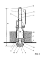
- FIG. 1 shows an inventive gowngarnitur 1, which is fixed in a conventional manner in an opening 23 of a cistern 3. Of the known cistern 3 only one area of the bottom is shown here. It is designed in a known manner so that it can absorb water 26 up to a level 22.
- An overflow pipe 11 has at an upper end an inlet opening 9, which is above the level 22 of the water 26.
- the overflow pipe 11 is liftably mounted in a housing 2 and has a known float 12 and a closing weight 21. To trigger a flush, the overflow pipe 11 is raised with an actuating device, not shown here. In of the FIG. 1 the overflow pipe 11 is shown in the raised state.
- a sealing element 4 is lifted from a valve seat 13, so that water 26 through the open valve according to the FIG. 2 can drain.
- the sealing element 4 is in communication with the overflow pipe 11 and the valve seat 13 is arranged on an outlet connection 8.
- the water 26 in this case flows through lateral openings 7 of the housing 2 in the outlet connection 8 and finally by a not shown with the outlet connection 8 in connection standing outgoing pipe in the Hopkins Remodelenden and not shown sanitary article.
- About the overflow pipe 11 can reach the outlet pipe 8 in a possible defect of the filling valve of the cistern, the rinse water so that it can not come to an overflow of the cistern.
- this flow is indicated by arrows 15.
- These arrows 15 correspond to the main flow. A portion of the water 26 of this main flow passes from below into the overflow pipe 11 and rises in this upwards.
- FIG. 2 showing a waste set without the feature essential to the invention
- the situation is shown before the complete emptying of the cistern.
- an air cone 5 is typically formed in the second half of the rinsing process, because air is sucked down through the overflow pipe 11 by the flow conditions.
- the rinse water rises in the overflow pipe 11. For example, to a level 18.
- the rinse water flows from the overflow pipe 11 in the direction of the outlet nozzle, wherein the drainage takes place at a higher speed as the drainage of the rinse water in the cistern.
- the drain fitting 1 according to the invention for a flushing cistern essentially comprises a valve seat 13, which, viewed in the flow direction, is arranged in front of an outlet opening 27.
- the valve seat 13 cooperates with a sealing element 4 of the overflow pipe 11.
- the overflow tube 11 is moved upwards, so that the contact between the sealing element 4 and the valve seat 13 is released. This position is shown in the figures. In the closed position, the sealing element 4 rests on the valve seat 13, so that no water can get out of the cistern through the outlet opening.
- the overflow tube 11 has a circumferential around a central axis M tube wall 14, an inlet opening 9 and an outlet opening 10.
- the circumferential tube wall 14 defines an interior space 24, which is accessible through said inlet opening 9 and the said outlet opening 10.
- the opening 16 has the function of reducing the height of the air column in the interior 24 of the overflow pipe 11.
- Rinse water penetrates through the opening 16 in the interior 24 in the lower region 17, wherein the area between the sealing element 4 and the valve seat 13 more or less complete filled with water, as in the FIG. 3 is shown. Due to the arrangement of the opening 16, the formation of an air cone 5 according to the FIG.
- the lower region 17 extends from the outlet opening 10 to the sealing element 4.
- the sealing element 4 is spaced from the outlet opening 10.
- the at least one opening 16 is, as already mentioned above, in this lower area 17. Thus, the at least one breakthrough between the tube outlet 10 and the sealing element. 4
- the at least one opening 16 extends completely through the pipe wall 14 of the overflow pipe 1 therethrough. Thus, an opening is provided which opens from the outside, outside the interior 24 of the overflow pipe 11, into the interior 24 of the overflow pipe 1.
- the opening 16 extends along an axis A.
- the axis A is substantially perpendicular to the central axis M of the overflow pipe 11.
- the axis A can also extend at an angle to the central axis M.
- the axis A is perpendicular to the surface through which the aperture extends.
- the at least one opening 16 is therefore a laterally arranged opening 16.
- this opening 16 runs along an axis A that is transverse to the center axis M.
- the overflow pipe 11 has in the lower region 17 via a conical portion 19 extending at least partially over the lower region.
- the lower region 17 is conical at least in sections.
- the overflow tube 11 here has a cylindrical section 20.
- the lower portion 17 is thus formed by the conical portion 19 and the cylindrical portion 20, wherein the conical portion 19 between the cylindrical portion 20 and the sealing element 4 is located.
- the at least one opening 16 is arranged here in the cylindrical section 20.
- the opening 16 may also be arranged in the conical section 19. It is also conceivable that the aperture extends from the cylindrical portion 20 into the conical portion 19.
- the conical portion 19 creates by its shape buoyancy on the overflow pipe 11 so that it can be kept open with less force. In addition, the flow in the Area positively influenced during the flushing process.
- a plurality of apertures 16 are distributed at regular intervals around the circumference in the overflow pipe 11.
- four circular openings 16, which may also be referred to as openings, are arranged.
- the four breakthroughs are spaced at an angle of 90 degrees to each other.
- the shape of the breakthrough 16 does not play a decisive role in the function. It is important that the breakthrough extends through the pipe wall 14 therethrough. But are particularly preferred breakthroughs with a circular cross-section, as well as in the FIG. 1 will be shown. But it is also conceivable that the breakthrough, for example, has a slit-like cross-section. Also, the arrangement of many small openings is conceivable.
- the outlet connection 8 has a substantially cylindrical design.
- This rounded edge 25 has a particular advantage on the water flow along the arrow 15 this particular in connection with the conical section 17th
- the overflow pipe 11 has a diameter of 28.5 mm in the present example.
- the circular openings 16 here have a diameter of 6 mm. Other dimensions are also conceivable.
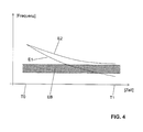
- FIG. 4 is the natural frequency E1 of the drain set without the invention essential feature and the natural frequency E2 of the drain set with the feature essential to the invention shown as a function of time.
- the time is shown on the X-axis and the frequency is shown on the Y-axis.
- the exciter frequency band EB of the running water At T0 the cistern is full and at T1 the cistern is empty.
- the exciter frequency band EB of the running water The natural frequencies decrease due to the leakage of water from the interior 14 of the overflow pipe 11 with decreasing water level in the interior 14.
- the natural frequency E1 decreases with increasing emptying so that it falls into the exciter frequency band EB, which then comes to said Gurgelgehoffschen.
- the natural frequency is determined by the height H1 of the air column, which is determined according to the FIG. 2 extends from the tip 6 of the air cone 5 up to the inlet opening 9.
- the height H2 of the air column can now be reduced.
- the characteristic of the natural frequency E2 is changed.
- the minimum natural frequency thus increases that the minimum natural frequency E2 no longer enters the excitation frequency band EB, and thus prevents the formation of a resonance.
Landscapes
- Health & Medical Sciences (AREA)
- Public Health (AREA)
- Life Sciences & Earth Sciences (AREA)
- Engineering & Computer Science (AREA)
- Hydrology & Water Resources (AREA)
- Water Supply & Treatment (AREA)
- Epidemiology (AREA)
- Sanitary Device For Flush Toilet (AREA)
- Self-Closing Valves And Venting Or Aerating Valves (AREA)
- Devices And Processes Conducted In The Presence Of Fluids And Solid Particles (AREA)
Abstract
Description
- Die vorliegende Erfindung betrifft eine Ablaufgarnitur für einen Spülkasten nach dem Oberbegriff von Anspruch 1.
- Bei den allgemein bekannten Ablaufgarnituren der genannten Art kann eine Spülung durch Anheben des Überlaufrohres ausgelöst werden. Das Anheben des Überlaufrohres erfolgt in der Regel mit einer Betätigungsvorrichtung, die beispielsweise eine Taste aufweist. Nach der Auslösung einer Spülung gelangt das im Spülkasten gelagerte Wasser infolge der Gravitation durch die Auslauföffnung in ein Ablaufrohr und schliesslich in eine WC-Schüssel oder in ein Urinal. Die Spülung wird unterbrochen, indem das Überlaufrohr auf den Ventilsitz fällt. Ein solcher Spülvorgang ist mit Geräuschen verbunden, die unterschiedliche Ursachen besitzen. Um diese Geräusche zu vermindern, ist bei der Ablaufgarnitur nach der
CH 676 263 A - In der
EP 1 854 926 wurde zwecks Verminderung der Spülgeräusche vorgeschlagen, mit einer Trenndüse das Entstehen von Wirbeln weitgehend zu verhindern. Mit diesem Ansatz konnten bezüglich der Reduktion der Geräusche zwar gute Erfolge erzielt werden, allerdings möchte man die Geräusche ohne Zusatzteile minimieren, weil die Ablaufgarnitur nach derEP 1 854 926 sehr aufwändig herstellbar. - Weiter wurde beobachtet, dass sich das Überlaufrohr bei Spülvorrichtungen aus dem Stand der Technik bei der Spülauslösung mit Wasser füllt. Das Wasser steigt also in das Überlaufrohr auf. Bei einem leicht späteren Zeitpunkt der Spülung entleert sich das Überlaufrohr in den Auslaufstutzen. Folglich wird also die Luftsäule im Überlaufrohr bei Beginn der Spülung mit dem Eintritt des Spülwassers verkürzt und dann während des Spülvorgangs wieder verlängert. Die Länge der Luftsäule bestimmt die akustische Eigenfrequenz des Überlaufrohrs. Wenn nun die Eigenfrequenz der Luftsäule in den Bereich des durch das Wasser entstehenden Erregerfrequenzbandes kommt, treten akustisch sehr gut wahrnehmbare und störende Gurgelgeräusche auf.
- Zudem können laute Gurgelgeräusche entstehen, welche durch das Ablösen der Wasserströmung am Konus in Kombination mit der Resonanzfrequenz der Luftsäule im Überlaufrohr oder Standrohr erzeugt werden.
- Ausgehend von diesem Stand der Technik liegt der Erfindung die Aufgabe zugrunde, eine Ablaufgarnitur anzugeben, welche die Nachteile des Standes der Technik überwindet. Insbesondere sollen die Geräusche weiter bzw. weitgehend minimiert werden. Weiter soll die Ablaufgarnitur einfacher herzustellen sein.
- Diese Aufgabe löst die Ablaufgarnitur nach Anspruch 1. Die Ablaufgarnitur für einen Spülkasten ist mit einem Ventilsitz der in Strömungsrichtung gesehen vor einer Auslauföffnung angeordnet ist, mit einem mit diesem Ventilsitz zusammenarbeitenden Dichtungselement eines Überlaufrohres, das zum Auslösen einer Spülung nach oben bewegt werden kann, ausgebildet. Das Überlaufrohr umfasst eine um eine Mittelachse umlaufende Rohrwandung, eine Eintrittsöffnung und eine Austrittsöffnung. Im unteren Bereich des Überlaufrohrs ist in der Rohrwandung mindestens ein Durchbruch angeordnet.
- Die Anordnung des mindestens einen Durchbruchs hat den Vorteil, dass die Länge der Luftsäule am Überlaufrohr reduziert werden kann oder sie mit der Länge des Überlaufrohrs begrenzt bleibt, wodurch die minimale Eigenfrequenz des Überlaufrohrs erhöht werden kann. Die Luftsäule kann sich also nicht auf eine resonanzkritische Länge erweitern. Durch die Erhöhung der minimalen Eigenfrequenz kommt es nicht zu einer Frequenzüberlagerung mit dem Frequenzband der Erregerfrequenz, welche durch das ablaufende Spülwasser generiert wird. Somit lassen sich die Resonanzen und die von den Resonanzen resultierenden Gurgelgeräusche vermeiden.
- Durch die Durchbrüche wird also eine Sekundärströmung zugelassen, welche die Luftsäule im Überlaufrohr entsprechend begrenzen. Diese Sekundärströmung wirkt zudem unterstützend auf den Volumenstrom und kann zudem verhindern, dass Wasser bei Beginn des Spülvorgangs in das Überlaufrohr sehr hoch ansteigt bzw. die Höhe des Ansteigens reduzieren.
- Zudem wird ein sehr einfach herzustellendes Element bereitgestellt, welches die allgemeine Anfälligkeit auf Geräusche einer solchen Ablaufgarnitur stark verbessert. Gegenüber der
EP 1 854 926 ist dies ein wesentlicher Vorteil, weil das Einpassen einer zusätzlichen Hülse entfällt. Weiter entfällt das Anordnen eines zusätzlichen Bauteils, um die Gurgelgeräusche zu verhindern. Es wird also auch Material eingespart. - Vorzugsweise erstreckt sich der untere Bereich von der Austrittsöffnung des Überlaufrohrs bis zum von der Austrittsöffnung beabstandet liegenden Dichtungselement, wobei der mindestens eine Durchbruch zwischen dem Rohraustritt und dem Dichtungselement angeordnet ist. Der mindestens eine Durchbruch liegt also unterhalb des Dichtungselementes.
- Der mindestens eine Durchbruch erstreckt sich vollständig durch die Rohrwandung des Überlaufrohrs hindurch.
- Der mindestens eine Durchbruch ist zusätzlich zur Austrittsöffnung angeordnet. Folglich umfasst der untere Bereich den im unteren Bereich liegenden Teil des Innenraums und der Rohrwandung des Überlaufrohrs, die Austrittsöffnung und den mindestens einen Durchbruch. Besonders bevorzugt besteht der untere Bereich aus dem im unteren Bereich liegenden Teil des Innenraums und der Rohrwandung des Überlaufrohrs, der Austrittsöffnung und dem mindestens einen Durchbruch.
- Vorzugsweise erstreckt sich der Durchbruch entlang einer Achse, welche im Wesentlichen rechtwinklig zur Mittelachse des Überlaufrohrs verläuft. Alternativ steht die Achse, entlang welcher der Durchbruch verläuft, im Wesentlichen rechtwinklig auf die Fläche der Rohrwandung, durch welche der Durchbruch sich hindurch erstreckt.
- Vorzugsweise weist das Überlaufrohr im unteren Bereich einen sich mindestens teilweise über den unteren Bereich erstreckenden konischen Abschnitt auf, wobei der Aussendurchmesser des Überlaufrohrs vom Dichtungselement zur Austrittsöffnung des Überlaufrohrs abnimmt. Das Überlaufrohr verläuft also im unteren Bereiche mindestens abschnittsweise konisch. Die konische Ausbildung hat den Vorteil, dass durch das bei der Spülung vorbeiströmende Wasser einen Auftrieb auf das Überlaufrohr wirkt.
- Vorzugsweise verläuft im unteren Bereich zwischen dem Dichtungselement und dem konischen Abschnitt das Überlaufrohr über einen zylindrischen Abschnitt zylindrisch. Der untere Bereich weist also in einer bevorzugten Ausgestaltung nach dem Dichtungselement einen zylindrischen Abschnitt und einen konischen Abschnitt auf, wobei der zylindrische Abschnitt zwischen dem konischen Abschnitt und dem Dichtungselement liegt.
- Vorzugsweise ist der mindestens eine Durchbruch im zylindrischen Abschnitt und/oder im konischen Abschnitt angeordnet. Der mindestens eine Durchbruch kann sich auch über den konischen und den zylindrischen Abschnitt erstrecken.
- Vorzugsweise sind mehrere Durchbrüche in regelmässigen Abständen um den Umfang verteilt im Überlaufrohr angeordnet.
- Besonders bevorzugt weist der mindestens eine Durchbruch einen runden Querschnitt aufweist. Der Durchbruch kann auch als Öffnung oder Bohrung bezeichnet werden. Alternativ kann der mindestens eine Durchbruch auch einen schlitzartigen Querschnitt aufweisen.
- Vorzugsweise erstreckt sich der untere Bereich nach unten in einen nach dem Ventilsitz angeordneten Auslaufstutzen, wenn das Dichtungselement auf dem Ventilsitz aufliegt.
- Der Auslaufstutzen weist vorzugsweise im Bereich unmittelbar nach dem Ventilsitz einen gerundeten Einlaufbereich auf.
- Weitere Ausführungsformen sind in den abhängigen Ansprüchen angegeben.
- Bevorzugte Ausführungsformen der Erfindung werden im Folgenden anhand der Zeichnungen beschrieben, die lediglich zur Erläuterung dienen und nicht einschränkend auszulegen sind. In den Zeichnungen zeigen:
- Fig. 1
- eine Schnittansicht einer Ablaufgarnitur gemäss einer Ausführungsform der Erfindung;
- Fig. 2
- eine Schnittansicht einer Ablaufgarnitur ohne die erfindungswesentlichen Merkmale mit eingezeichneten Wasserstand im Spülkasten;
- Fig. 3
- eine Schnittansicht der Ablaufgarnitur nach der
Fig. 1 mit eingezeichnetem Wasserstand; und - Fig. 4
- eine schematische Darstellung der Frequenzentwicklung beim Ablauf des Spülwasser durch die Ablaufgarnitur der
Figur 1 und derFigur 2 . - Die
Figur 1 zeigt eine erfindungsgemässe Ablaufgarnitur 1, die in an sich bekannter Weise in einer Öffnung 23 eines Spülkastens 3 befestigt ist. Von dem an sich bekannten Spülkasten 3 ist hier lediglich ein Bereich des Bodens gezeigt. Er ist in bekannter Weise so ausgebildet, dass er Wasser 26 bis zu einem Niveau 22 aufnehmen kann. Ein Überlaufrohr 11 besitzt an einem oberen Ende eine Eintrittsöffnung 9, die über dem Niveau 22 des Wassers 26 liegt. Am unteren Ende besitzt das Überlaufrohr 11 eine Austrittsöffnung 10. Das Überlaufrohr 11 ist anhebbar in einem Gehäuse 2 gelagert und besitzt einen an sich bekannten Schwimmer 12 und ein Schliessgewicht 21. Zur Auslösung einer Spülung wird das Überlaufrohr 11 mit einer hier nicht gezeigten Betätigungsvorrichtung angehoben. In derFigur 1 wird das Überlaufrohr 11 im angehobenen Zustand gezeigt. Hierbei wird ein Dichtungselement 4 von einem Ventilsitz 13 abgehoben, so dass Wasser 26 durch das geöffnete Ventil gemäss derFigur 2 abfliessen kann. Das Dichtungselement 4 steht mit dem Überlaufrohr 11 in Verbindung und der Ventilsitz 13 ist an einem Auslaufstutzen 8 angeordnet. Das Wasser 26 strömt hierbei durch seitliche Öffnungen 7 des Gehäuses 2 in den Auslaufstutzen 8 und schliesslich durch ein nicht gezeigtes mit dem Auslaufstutzen 8 in Verbindung stehendes Abgangsrohr in den auszuspülenden und hier nicht gezeigten Sanitärartikel. Über das Überlaufrohr 11 kann bei einem allfälligen Defekt des Füllventils des Spülkastens, das Spülwasser in den Auslaufstutzen 8 gelangen, so dass es nicht zu einem Überlaufen des Spülkastens kommen kann. - In der
Figur 1 ist diese Strömung mit Pfeilen 15 angedeutet. Diese Pfeile 15 entsprechen der Hauptströmung. Ein Teil des Wassers 26 dieser Hauptströmung gelangt von unten in das Überlaufrohr 11 und steigt in diesem nach oben. - In der
Figur 2 , welche eine Ablaufgarnitur ohne das erfindungswesentliche Merkmal zeigt, wird die Situation vor dem vollständigen Entleeren des Spülkastens dargestellt. Unterhalb des Überlaufrohrs 11 im Abgangsrohr 10 bildet sich typischerweise in der zweiten Hälfte des Spülvorgangs ein Luftkegel 5, weil durch die Strömungsverhältnisse Luft durch das Überlaufrohr 11 nach unten gesogen wird. Kurz nach dem Anheben des Überlaufrohrs 11 steigt das Spülwasser in das Überlaufrohr 11 auf. Beispielsweise auf ein Niveau 18. Anschliessend fliesst das Spülwasser aus dem Überlaufrohr 11 in Richtung Auslaufstutzen ab, wobei das Abfliessen mit einer höheren Geschwindigkeit erfolgt wie das Ablaufen des Spülwassers im Spülkasten. Folglich kommt es zur Situation, dass im Überlaufrohr 11 nur noch Luft vorhanden ist und im Spülkasten 3 Spülwasser 26 vorhanden ist. Diese Situation wird in derFigur 2 gezeigt. Durch den Luftkegel 5 wird eine Luftsäule von der Spitze 6 des Luftkegels 5 bis hin zur Eintrittsöffnung 9 gebildet. Diese Luftsäule weist eine maximale Höhe H1 auf. Die Höhe H1 ist dabei Wesentlich für die Eigenfrequenz der Ablaufgarnitur 1, wie dies untenstehend im Zusammenhang mit derFigur 4 erläutert wird. - Mit Bezug auf die
Figuren 1 und3 wird nun eine Ausführungsform der Erfindung genauer beschrieben. - Die erfindungsgemässe Ablaufgarnitur 1 für einen Spülkasten umfasst im Wesentlichen einen Ventilsitz 13, der in Strömungsrichtung gesehen vor einer Auslauföffnung 27 angeordnet ist. Der Ventilsitz 13 arbeitet mit einem Dichtungselement 4 des Überlaufrohrs 11 zusammen. Zum Auslösen einer Spülung wird das Überlaufrohr 11 nach oben bewegt, so dass der Kontakt zwischen dem Dichtungselement 4 und dem Ventilsitz 13 aufgehoben wird. Diese Stellung wird in den Figuren gezeigt. In der Verschlussstellung liegt das Dichtungselement 4 auf dem Ventilsitz 13 auf, sodass kein Wasser aus dem Spülkasten durch die Auslauföffnung gelangen kann.
- Das Überlaufrohr 11 weist eine sich um eine Mittelachse M umlaufende Rohrwandung 14, eine Eintrittsöffnung 9 und eine Austrittsöffnung 10 auf. Die umlaufende Rohrwandung 14 definiert dabei einen Innenraum 24, welcher durch besagte Eintrittsöffnung 9 und die besagte Austrittsöffnung 10 zugänglich ist. Im unteren Bereich 17 des Überlaufrohrs 11 ist in der Rohrwandung 14 mindestens ein Durchbruch 16 angeordnet. Der Durchbruch 16 hat die Funktion der Reduzierung der Höhe der Luftsäule im Innenraum 24 des Überlaufrohrs 11. Spülwasser dringt durch den Durchbruch 16 in den Innenraum 24 im unteren Bereich 17 ein, wobei der Bereich zwischen dem Dichtungselement 4 und den Ventilsitz 13 mehr oder weniger vollständig mit Wasser gefüllt, so wie dies in der
Figur 3 dargestellt ist. Durch die Anordnung des Durchbruches 16 wird die Bildung eines Luftkegels 5 gemäss derFigur 2 verhindert, wobei die für die Eigenfrequenz verantwortliche Höhe der Luftsäule von der Höhe H1 (sieheFigur 2 ) auf die Höhe H2 (sieheFigur 3 ) reduziert werden. Es können durch die Reduktion der Luftsäule Geräusche, insbesondere die Gurgelgeräusche beim Spülvorgang, signifikant reduziert werden, was im Zusammenhang mit derFigur 4 noch detailliert erläutert wird. - Der untere Bereich 17 erstreckt sich von der Austrittsöffnung 10 bis hin zum Dichtungselement 4. Das Dichtungselement 4 liegt dabei beabstandet zur Austrittsöffnung 10. Der mindestens eine Durchbruch 16 liegt, wie oben bereits erwähnt, in diesem unteren Bereich 17. Somit liegt der mindestens eine Durchbruch zwischen dem Rohraustritt 10 und dem Dichtungselement 4.
- Prinzipiell kann gesagt werden, dass je höher der mindestens eine Durchbruch 16 liegt, ein besseres Resultat erzielt werden kann, weil die minimale Eigenfrequenz entsprechend erhöht wird.
- Der mindestens eine Durchbruch 16 erstreckt sich vollständig durch die Rohrwandung 14 des Überlaufrohres 1 hindurch. Es wird also ein Durchbruch bereitgestellt, welcher von der Aussenseite, ausserhalb des Innenraums 24 des Überlaufrohrs 11, in den Innenraum 24 des Überlaufrohrs 1 mündet.
- Der Durchbruch 16 erstreckt sich entlang einer Achse A. Die Achse A liegt im Wesentlichen rechtwinklig zur Mittelachse M des Überlaufrohrs 11. Alternativ kann die Achse A auch Winklig zur Mittelachse M verlaufen. Besonders bevorzugt liegt die Achse A rechtwinklig auf die Fläche, durch welche der Durchbruch sich hindurch erstreckt. Es handelt sich beim mindestens einem Durchbruch 16 also um einen seitlich angeordneten Durchbruch 16. Vorzugsweise verläuft dieser Durchbruch 16 entlang einer quer zur Mittelachse M stehenden Achse A.
- Von den
Figuren 1 und3 kann gut erkannt werden, dass das Überlaufrohr 11 im unteren Bereich 17 über einen sich mindestens teilweise über den unteren Bereich erstreckenden konischen Abschnitt 19 verfügt. Mit anderen Worten kann gesagt werden, dass der untere Bereich 17 mindestens abschnittsweise konisch ausgebildet ist. - Im unteren Bereich 17 zwischen dem Dichtungselement 4 und dem konischen Abschnitt 19 weist das Überlaufrohr 11 hier einen zylindrischen Abschnitt 20 auf. In der vorliegenden Ausführungsform wird der untere Bereich 17 also durch den konischen Abschnitt 19 und den zylindrischen Abschnitt 20 ausgebildet, wobei der konische Abschnitt 19 zwischen dem zylindrischen Abschnitt 20 und dem Dichtungselement 4 liegt.
- Der mindestens eine Durchbruch 16 ist hier im zylindrischen Abschnitt 20 angeordnet. Alternativ oder zusätzlich kann der Durchbruch 16 auch im konischen Abschnitt 19 angeordnet sein. Auch ist es denkbar, dass sich der Durchbruch vom zylindrischen Abschnitt 20 in den konischen Abschnitt 19 hineinerstreckt.
- Der konische Abschnitt 19 erzeugt durch seine Form einen Auftrieb auf das Überlaufrohr 11, sodass es mit weniger Kraft offen gehalten werden kann. Zudem wird die Strömung im Bereich beim Spülvorgang positiv beeinflusst.
- Vorzugsweise sind mehrere Durchbrüche 16 in regelmässigen Abständen um den Umfang verteilt im Überlaufrohr 11 angeordnet. In der gezeigten Ausführungsform sind vier kreisrunde Durchbrüche 16, die auch als Öffnungen bezeichnet werden können, angeordnet. Die vier Durchbrüche liegen in einem Winkel von 90 Grad beanstandet zueinander.
- Die Form des Durchbruches 16 spielt für die Funktion keine entscheidende Rolle. Wichtig ist, dass sich der Durchbruch durch die Rohrwandung 14 hindurch erstreckt. Besonders bevorzugt werden aber Durchbrüche mit einem kreisrunden Querschnitt, sowie dies in der
Figur 1 gezeigt wird. Aber es ist auch denkbar, dass der Durchbruch beispielsweise einen schlitzartigen Querschnitt aufweist. Auch ist die Anordnung von vielen kleinen Öffnungen denkbar. - Wenn das Dichtungselement 4 auf dem Ventilsitz 13 aufliegt, erstreckt sich der untere Bereich 17 nach unten in den nach dem Ventilsitz 13 angeordneten Auslaufstutzen 8. Der Auslaufstutzen 8 weist eine im Wesentlichen zylindrische Ausbildung auf. Im oberen Bereich, kurz nach dem Ventilsitz 13 ist der Auslaufstutzen 8 auf seiner Innenseite mit einer gerundeten Kante 25 ausgebildet. Diese gerundete Kante 25 hat einen besonderen Vorteil auf den Wasserfluss entlang des Pfeils 15 dies insbesondere im Zusammenhang mit dem konischen Abschnitt 17.
- Bezüglich der Länge des unteren Bereichs 17, welche in der
Figur 1 das Bezugszeichen L trägt, ist es besonders Vorteilhaft, dass diese kleiner ist als der maximale Durchmesser des Überlaufrohres 11 in diesem unteren Bereich. - Das Überlaufrohr 11 weist im vorliegenden Beispiel einen Durchmesser von 28,5 mm auf. Die kreisrunden Durchbrüche 16 weisen hier einen Durchmesser von 6 mm auf. Andere Abmessungen sind aber auch denkbar.
- In der
Figur 4 wird die Eigenfrequenz E1 der Ablaufgarnitur ohne das erfindungswesentliche Merkmal und die Eigenfrequenz E2 der Ablaufgarnitur mit dem erfindungswesentlichen Merkmal in Abhängigkeit mit der Zeit gezeigt. Auf der X-Achse ist die Zeit abgebildet und auf der Y-Achse ist die Frequenz abgebildet. Bei T0 ist der Spülkasten voll und bei T1 ist der Spülkasten entleert. Weiter wird in derFigur 4 das Erregerfrequenzband EB des ablaufenden Wassers gezeigt. Die Eigenfrequenzen nehmen aufgrund des Auslaufens des Wassers aus dem Innenraum 14 des Überlaufrohrs 11 mit sinkendem Wasserstand im Innenraum 14 ab. - Von der
Figur 4 kann nun gut erkannt werden, dass mit der Ablaufgarnitur ohne den Durchbruch 16 im unteren Bereich 17, die Eigenfrequenz E1 bei zunehmender Entleerung derart abnimmt, dass diese in das Erregerfrequenzband EB fällt, wobei es dann zu den besagten Gurgelgeräuschen kommt. Die Eigenfrequenz wird durch die Höhe H1 der Luftsäule bestimmt, welche sich gemäss derFigur 2 von der Spitze 6 des Luftkegels 5 bis hin zur Eintrittsöffnung 9 erstreckt. - Durch das erfindungswesentliche Merkmal, sprich den Durchbruch 16, kann nun die Höhe H2 der Luftsäule verringert werden. Hierdurch wird auch die Charakteristik der Eigenfrequenz E2 verändert. Die minimale Eigenfrequenz erhöht sich somit, dass die minimale Eigenfrequenz E2 nicht mehr in das Erregerfrequenzband EB eintritt, und somit die Entstehung einer Resonanz verhindert.
- Diese Effekte bezüglich der Verkürzung der Luftsäule im Überlaufohr 11 treten insbesondere dann ein, wenn es im Auslaufstutzen 8 zu einer Vollfüllung kommt.
- In den Figuren wir eine besonders bevorzugte Ablaufgarnitur gezeigt. Die Ausbildung der Ablaufgarnitur kann im Sinne der Erfindung aber auch anders ausgebildet sein.
-
- 1
- Ablaufgarnitur
- 2
- Gehäuse
- 3
- Spülkasten
- 4
- Dichtungselement (Ventilteller)
- 5
- Luftkegel
- 6
- Spitze des Luftkegels
- 7
- Öffnung
- 8
- Auslaufstutzen
- 9
- Eintrittsöffnung
- 10
- Austrittsöffnung
- 11
- Überlaufrohr
- 12
- Schwimmer
- 13
- Ventilsitz
- 14
- Rohrwandung
- 15
- Pfeil
- 16
- Durchbruch
- 17
- unterer Bereich
- 18
- Wasserniveau
- 19
- konischer Abschnitt
- 20
- zylindrischer Abschnitt
- 21
- Gewicht
- 22
- Wasserniveau
- 23
- Öffnung
- 24
- Innenraum
- 25
- Kante
- 26
- Wasser
- 27
- Auslauföffnung
- D
- Durchmesser
- L
- Länge
- H1
- Höhe 1
- H2
- Höhe 2
- E1
- Eigenfrequenz
- E2
- Eigenfrequenz
- T0
- Spülkasten voll
- T1
- Spülkasten leer
Claims (13)
- Ablaufgarnitur für einen Spülkasten, mit einem Ventilsitz (13) der in Strömungsrichtung gesehen vor einer Auslauföffnung (27) angeordnet ist, mit einem mit diesem Ventilsitz (13) zusammenarbeitenden Dichtungselement (4) eines Überlaufrohres (11), das zum Auslösen einer Spülung nach oben bewegt werden kann, wobei das Überlaufrohr (11) eine um eine Mittelachse (M) umlaufende Rohrwandung (14), eine Eintrittsöffnung (9) und einen Austrittsöffnung (10) aufweist, dadurch gekennzeichnet, dass im unteren Bereich (17) des Überlaufrohrs (11) in der Rohrwandung (14) mindestens ein Durchbruch (16) angeordnet ist.
- Ablaufgarnitur nach Anspruch 1, dadurch gekennzeichnet, dass sich der untere Bereich (17) von der Austrittsöffnung (10) bis zum von der Austrittsöffnung (10) beabstandet liegenden Dichtungselement (4) erstreckt, wobei der mindestens eine Durchbruch (16) zwischen dem Rohraustritt (10) und dem Dichtungselement (4) angeordnet ist.
- Ablaufgarnitur nach einem der vorhergehenden Ansprüche, dadurch gekennzeichnet, dass der mindestens eine Durchbruch (16) sich vollständig durch die Rohrwandung (14) des Überlaufrohrs (11) hindurch erstreckt.
- Ablaufgarnitur nach einem der vorhergehenden Ansprüche, dadurch gekennzeichnet, dass der Durchbruch (16) zusätzlich zur Austrittsöffnung (10) angeordnet ist, wobei der untere Bereich den im unteren Bereich liegenden Teil der Rohrwandung (14) und des Innenraums (24) des Überlaufrohrs (11), die Austrittsöffnung (10) und den mindestens einen Durchbruch (16) umfasst bzw. daraus besteht.
- Ablaufgarnitur nach einem der vorhergehenden Ansprüche, dadurch gekennzeichnet, dass sich der Durchbruch (16) entlang einer Achse (A) erstreckt, welche im Wesentlichen rechtwinklig zur Mittelachse (M) verläuft, oder welche im Wesentlichen rechtwinklig auf die Fläche der Rohrwandung (14) steht, durch welche der Durchbruch (16) sich hindurch erstreckt.
- Ablaufgarnitur nach einem der vorhergehenden Ansprüche, dadurch gekennzeichnet, dass das Überlaufrohr (11) im unteren Bereich (17) einen sich mindestens teilweise über den unteren Bereich (17) erstreckenden konischen Abschnitt (19) aufweist, wobei der Aussendurchmesser des Überlaufrohrs (11) vom Dichtungselement (4) zur Austrittsöffnung (10) abnimmt.
- Ablaufgarnitur nach Anspruch 6, dadurch gekennzeichnet, dass im unteren Bereich (17) zwischen dem Dichtungselement (4) und dem konischen Abschnitt (19) das Überlaufrohr (11) über einen zylindrischen Abschnitt (20) zylindrisch verläuft.
- Ablaufgarnitur nach Anspruch 7, dadurch gekennzeichnet, dass der mindestens eine Durchbruch (16) im zylinderischen Abschnitt (20) und/oder im konischen Abschnitt (19) angeordnet ist.
- Ablaufgarnitur nach einem der vorhergehenden Ansprüche, dadurch gekennzeichnet, dass mehrere Durchbrüche (16) in regelmässigen Abständen um den Umfang verteilt im Überlaufrohr (11) angeordnet sind.
- Ablaufgarnitur nach einem der vorhergehenden Ansprüche, dadurch gekennzeichnet, dass der mindestens eine Durchbruch (16) einen runden Querschnitt aufweist, und/oder dass der mindestens eine Durchbruch (16) einen schlitzartigen Querschnitt aufweist.
- Ablaufgarnitur nach einem der vorhergehenden Ansprüche, dadurch gekennzeichnet, dass die Länge (L) des unteren Bereichs (17) von der Austrittsöffnung (10) entlang der Mittelachse (M) bis zum Dichtungselement (4) kleiner ist als der maximale Durchmesser des Überlaufrohrs (11) in diesem unteren Bereich (17).
- Ablaufgarnitur nach einem der vorhergehenden Ansprüche, dadurch gekennzeichnet, dass sich der untere Bereich (17) nach unten in einen nach dem Ventilsitz (13) angeordneten Auslaufstutzen (8) erstreckt, wenn das Dichtungselement (4) auf dem Ventilsitz (13) aufliegt.
- Ablaufgarnitur nach einem der vorhergehenden Ansprüche, dadurch gekennzeichnet, dass der Auslaufstutzen (27) vorzugsweise im Bereich unmittelbar nach dem Ventilsitz (13) einen gerundeten Einlaufbereich (25) aufweist.
Priority Applications (2)
| Application Number | Priority Date | Filing Date | Title |
|---|---|---|---|
| EP13154398.5A EP2765249B1 (de) | 2013-02-07 | 2013-02-07 | Ablaufgarnitur für einen Spülkasten |
| CN201410036581.4A CN103981934A (zh) | 2013-02-07 | 2014-01-24 | 用于冲水箱的排水配件 |
Applications Claiming Priority (1)
| Application Number | Priority Date | Filing Date | Title |
|---|---|---|---|
| EP13154398.5A EP2765249B1 (de) | 2013-02-07 | 2013-02-07 | Ablaufgarnitur für einen Spülkasten |
Publications (2)
| Publication Number | Publication Date |
|---|---|
| EP2765249A1 true EP2765249A1 (de) | 2014-08-13 |
| EP2765249B1 EP2765249B1 (de) | 2018-01-03 |
Family
ID=47709967
Family Applications (1)
| Application Number | Title | Priority Date | Filing Date |
|---|---|---|---|
| EP13154398.5A Active EP2765249B1 (de) | 2013-02-07 | 2013-02-07 | Ablaufgarnitur für einen Spülkasten |
Country Status (2)
| Country | Link |
|---|---|
| EP (1) | EP2765249B1 (de) |
| CN (1) | CN103981934A (de) |
Cited By (1)
| Publication number | Priority date | Publication date | Assignee | Title |
|---|---|---|---|---|
| WO2017212068A2 (de) | 2016-06-10 | 2017-12-14 | Tece Gmbh | Ablaufventil |
Families Citing this family (3)
| Publication number | Priority date | Publication date | Assignee | Title |
|---|---|---|---|---|
| US10711444B2 (en) | 2016-11-01 | 2020-07-14 | Kohler Co. | Toilet inlet configuration |
| CN106759750B (zh) * | 2017-01-03 | 2023-04-14 | 厦门瑞尔特卫浴科技股份有限公司 | 一种带溢流管的排水阀降噪结构 |
| EP3392418B1 (de) * | 2017-04-19 | 2020-04-29 | Geberit International AG | Befestigungssystem |
Citations (5)
| Publication number | Priority date | Publication date | Assignee | Title |
|---|---|---|---|---|
| US386918A (en) * | 1888-07-31 | John demaeest | ||
| FR1191899A (fr) * | 1958-02-22 | 1959-10-22 | Pour Les Applic Des Matieres P | Perfectionnement aux réservoirs de chasse |
| EP0333652A1 (de) * | 1988-03-16 | 1989-09-20 | Geberit AG | Vorrichtung zur Geräuschdämpfung des Wasseraustritts, insbesondere durch das Auslaufventil eines Klosettspülkastens |
| CH676263A5 (de) | 1988-07-05 | 1990-12-28 | Geberit Ag | |
| EP1854926A1 (de) | 2006-05-11 | 2007-11-14 | Geberit Technik Ag | Ablaufgarnitur für einen Spülkasten |
Family Cites Families (5)
| Publication number | Priority date | Publication date | Assignee | Title |
|---|---|---|---|---|
| BE647271A (de) * | ||||
| FR2621630B1 (fr) * | 1987-10-09 | 1989-12-15 | Pocachard Thierry | Mecanisme de commande de chasse d'eau pour wc par poussoir |
| ES2257969B1 (es) * | 2004-12-17 | 2007-08-16 | Fominaya, S.A. | Dispositivo de evacuacion para cisternas o depositos con valvula de descarga. |
| CN201024492Y (zh) * | 2007-04-17 | 2008-02-20 | 赵丕君 | 马桶节水冲水阀 |
| CN201165690Y (zh) * | 2008-01-04 | 2008-12-17 | 彭东 | 排水阀止水下盖结构 |
-
2013
- 2013-02-07 EP EP13154398.5A patent/EP2765249B1/de active Active
-
2014
- 2014-01-24 CN CN201410036581.4A patent/CN103981934A/zh active Pending
Patent Citations (5)
| Publication number | Priority date | Publication date | Assignee | Title |
|---|---|---|---|---|
| US386918A (en) * | 1888-07-31 | John demaeest | ||
| FR1191899A (fr) * | 1958-02-22 | 1959-10-22 | Pour Les Applic Des Matieres P | Perfectionnement aux réservoirs de chasse |
| EP0333652A1 (de) * | 1988-03-16 | 1989-09-20 | Geberit AG | Vorrichtung zur Geräuschdämpfung des Wasseraustritts, insbesondere durch das Auslaufventil eines Klosettspülkastens |
| CH676263A5 (de) | 1988-07-05 | 1990-12-28 | Geberit Ag | |
| EP1854926A1 (de) | 2006-05-11 | 2007-11-14 | Geberit Technik Ag | Ablaufgarnitur für einen Spülkasten |
Cited By (3)
| Publication number | Priority date | Publication date | Assignee | Title |
|---|---|---|---|---|
| WO2017212068A2 (de) | 2016-06-10 | 2017-12-14 | Tece Gmbh | Ablaufventil |
| DE102016110694A1 (de) | 2016-06-10 | 2017-12-14 | Tece Gmbh | Ablaufventil |
| WO2017212068A3 (de) * | 2016-06-10 | 2018-02-01 | Tece Gmbh | Ablaufventil |
Also Published As
| Publication number | Publication date |
|---|---|
| CN103981934A (zh) | 2014-08-13 |
| EP2765249B1 (de) | 2018-01-03 |
Similar Documents
| Publication | Publication Date | Title |
|---|---|---|
| EP2765249B1 (de) | Ablaufgarnitur für einen Spülkasten | |
| EP3469158B1 (de) | Ablaufventil | |
| DE102009010862B4 (de) | Geruchsverschluss für ein Vakuumtoilettenabflusssystem, Ablaufvorrichtung, Vakuumtoilettensystem sowie Flugzeug mit einem solchen Vakuumtoilettensystem | |
| EP2508686B1 (de) | Rückhalteanlage für Niederschlagwasser und Abwasser | |
| DE202014007392U1 (de) | Wasserablauf mit Mehrfachsiphon-Geruchsverschluss | |
| EP1854926B1 (de) | Ablaufgarnitur für einen Spülkasten | |
| EP2369088B1 (de) | Vorrichtung zur Dachentwässerung | |
| EP2871294B1 (de) | Einlaufgarnitur für einen Spülkasten | |
| EP2700759A1 (de) | Einlaufgarnitur für einen Spülkasten | |
| EP1449968A2 (de) | Wasserkasten für ein Klosett und entsprechendes Klosett | |
| EP2829666B1 (de) | Einlaufgarnitur für einen Spülkasten | |
| EP3538716B1 (de) | Ablaufgarnitur | |
| EP1484453B1 (de) | Uberlauf- und Ablaufgarnitur für sanitäre Apparate | |
| EP2505727B1 (de) | Ablaufventil für einen Spülkasten | |
| EP3321431B1 (de) | Ablaufgarnitur | |
| EP2995731B1 (de) | Wasserablauf mit Mehrfachsiphon-Geruchsverschluss | |
| CH711775B1 (de) | Überlauf für eine Spüle. | |
| EP4095323B1 (de) | Spülsystem | |
| EP0757135A1 (de) | Spülkasten | |
| DE29906646U1 (de) | Ablaufgarnitur für einen Spülkasten | |
| DE688902C (de) | Abtrittspuelvorrichtung mit Bodenventil | |
| EP3321432B1 (de) | Ablaufgarnitur | |
| WO1997022761A1 (de) | Vorrichtung zu einem spülkasten | |
| EP3848519A1 (de) | Sanitäreinrichtung umfassend ein urinal und einen an das urinal anzuschliessenden oder angeschlossenen absaugsiphon sowie eine spüldüse | |
| EP2865818B1 (de) | Hydraulische Ablaufgarnitur |
Legal Events
| Date | Code | Title | Description |
|---|---|---|---|
| PUAI | Public reference made under article 153(3) epc to a published international application that has entered the european phase |
Free format text: ORIGINAL CODE: 0009012 |
|
| 17P | Request for examination filed |
Effective date: 20130207 |
|
| AK | Designated contracting states |
Kind code of ref document: A1 Designated state(s): AL AT BE BG CH CY CZ DE DK EE ES FI FR GB GR HR HU IE IS IT LI LT LU LV MC MK MT NL NO PL PT RO RS SE SI SK SM TR |
|
| AX | Request for extension of the european patent |
Extension state: BA ME |
|
| R17P | Request for examination filed (corrected) |
Effective date: 20141220 |
|
| RBV | Designated contracting states (corrected) |
Designated state(s): AL AT BE BG CH CY CZ DE DK EE ES FI FR GB GR HR HU IE IS IT LI LT LU LV MC MK MT NL NO PL PT RO RS SE SI SK SM TR |
|
| 17Q | First examination report despatched |
Effective date: 20160729 |
|
| GRAP | Despatch of communication of intention to grant a patent |
Free format text: ORIGINAL CODE: EPIDOSNIGR1 |
|
| INTG | Intention to grant announced |
Effective date: 20170721 |
|
| GRAS | Grant fee paid |
Free format text: ORIGINAL CODE: EPIDOSNIGR3 |
|
| GRAA | (expected) grant |
Free format text: ORIGINAL CODE: 0009210 |
|
| AK | Designated contracting states |
Kind code of ref document: B1 Designated state(s): AL AT BE BG CH CY CZ DE DK EE ES FI FR GB GR HR HU IE IS IT LI LT LU LV MC MK MT NL NO PL PT RO RS SE SI SK SM TR |
|
| REG | Reference to a national code |
Ref country code: GB Ref legal event code: FG4D Free format text: NOT ENGLISH |
|
| REG | Reference to a national code |
Ref country code: CH Ref legal event code: EP Ref country code: AT Ref legal event code: REF Ref document number: 960409 Country of ref document: AT Kind code of ref document: T Effective date: 20180115 |
|
| REG | Reference to a national code |
Ref country code: IE Ref legal event code: FG4D Free format text: LANGUAGE OF EP DOCUMENT: GERMAN |
|
| REG | Reference to a national code |
Ref country code: CH Ref legal event code: NV Representative=s name: ISLER AND PEDRAZZINI AG, CH |
|
| REG | Reference to a national code |
Ref country code: DE Ref legal event code: R096 Ref document number: 502013009156 Country of ref document: DE |
|
| REG | Reference to a national code |
Ref country code: FR Ref legal event code: PLFP Year of fee payment: 6 |
|
| REG | Reference to a national code |
Ref country code: NL Ref legal event code: MP Effective date: 20180103 |
|
| REG | Reference to a national code |
Ref country code: LT Ref legal event code: MG4D |
|
| REG | Reference to a national code |
Ref country code: NO Ref legal event code: T2 Effective date: 20180103 |
|
| PG25 | Lapsed in a contracting state [announced via postgrant information from national office to epo] |
Ref country code: NL Free format text: LAPSE BECAUSE OF FAILURE TO SUBMIT A TRANSLATION OF THE DESCRIPTION OR TO PAY THE FEE WITHIN THE PRESCRIBED TIME-LIMIT Effective date: 20180103 |
|
| PG25 | Lapsed in a contracting state [announced via postgrant information from national office to epo] |
Ref country code: LT Free format text: LAPSE BECAUSE OF FAILURE TO SUBMIT A TRANSLATION OF THE DESCRIPTION OR TO PAY THE FEE WITHIN THE PRESCRIBED TIME-LIMIT Effective date: 20180103 Ref country code: ES Free format text: LAPSE BECAUSE OF FAILURE TO SUBMIT A TRANSLATION OF THE DESCRIPTION OR TO PAY THE FEE WITHIN THE PRESCRIBED TIME-LIMIT Effective date: 20180103 Ref country code: HR Free format text: LAPSE BECAUSE OF FAILURE TO SUBMIT A TRANSLATION OF THE DESCRIPTION OR TO PAY THE FEE WITHIN THE PRESCRIBED TIME-LIMIT Effective date: 20180103 Ref country code: FI Free format text: LAPSE BECAUSE OF FAILURE TO SUBMIT A TRANSLATION OF THE DESCRIPTION OR TO PAY THE FEE WITHIN THE PRESCRIBED TIME-LIMIT Effective date: 20180103 Ref country code: CY Free format text: LAPSE BECAUSE OF FAILURE TO SUBMIT A TRANSLATION OF THE DESCRIPTION OR TO PAY THE FEE WITHIN THE PRESCRIBED TIME-LIMIT Effective date: 20180103 |
|
| PG25 | Lapsed in a contracting state [announced via postgrant information from national office to epo] |
Ref country code: LV Free format text: LAPSE BECAUSE OF FAILURE TO SUBMIT A TRANSLATION OF THE DESCRIPTION OR TO PAY THE FEE WITHIN THE PRESCRIBED TIME-LIMIT Effective date: 20180103 Ref country code: SE Free format text: LAPSE BECAUSE OF FAILURE TO SUBMIT A TRANSLATION OF THE DESCRIPTION OR TO PAY THE FEE WITHIN THE PRESCRIBED TIME-LIMIT Effective date: 20180103 Ref country code: RS Free format text: LAPSE BECAUSE OF FAILURE TO SUBMIT A TRANSLATION OF THE DESCRIPTION OR TO PAY THE FEE WITHIN THE PRESCRIBED TIME-LIMIT Effective date: 20180103 Ref country code: PL Free format text: LAPSE BECAUSE OF FAILURE TO SUBMIT A TRANSLATION OF THE DESCRIPTION OR TO PAY THE FEE WITHIN THE PRESCRIBED TIME-LIMIT Effective date: 20180103 Ref country code: GR Free format text: LAPSE BECAUSE OF FAILURE TO SUBMIT A TRANSLATION OF THE DESCRIPTION OR TO PAY THE FEE WITHIN THE PRESCRIBED TIME-LIMIT Effective date: 20180404 Ref country code: IS Free format text: LAPSE BECAUSE OF FAILURE TO SUBMIT A TRANSLATION OF THE DESCRIPTION OR TO PAY THE FEE WITHIN THE PRESCRIBED TIME-LIMIT Effective date: 20180503 Ref country code: BG Free format text: LAPSE BECAUSE OF FAILURE TO SUBMIT A TRANSLATION OF THE DESCRIPTION OR TO PAY THE FEE WITHIN THE PRESCRIBED TIME-LIMIT Effective date: 20180403 |
|
| PG25 | Lapsed in a contracting state [announced via postgrant information from national office to epo] |
Ref country code: MT Free format text: LAPSE BECAUSE OF FAILURE TO SUBMIT A TRANSLATION OF THE DESCRIPTION OR TO PAY THE FEE WITHIN THE PRESCRIBED TIME-LIMIT Effective date: 20180103 |
|
| REG | Reference to a national code |
Ref country code: DE Ref legal event code: R097 Ref document number: 502013009156 Country of ref document: DE |
|
| PG25 | Lapsed in a contracting state [announced via postgrant information from national office to epo] |
Ref country code: AL Free format text: LAPSE BECAUSE OF FAILURE TO SUBMIT A TRANSLATION OF THE DESCRIPTION OR TO PAY THE FEE WITHIN THE PRESCRIBED TIME-LIMIT Effective date: 20180103 Ref country code: MC Free format text: LAPSE BECAUSE OF FAILURE TO SUBMIT A TRANSLATION OF THE DESCRIPTION OR TO PAY THE FEE WITHIN THE PRESCRIBED TIME-LIMIT Effective date: 20180103 Ref country code: EE Free format text: LAPSE BECAUSE OF FAILURE TO SUBMIT A TRANSLATION OF THE DESCRIPTION OR TO PAY THE FEE WITHIN THE PRESCRIBED TIME-LIMIT Effective date: 20180103 Ref country code: RO Free format text: LAPSE BECAUSE OF FAILURE TO SUBMIT A TRANSLATION OF THE DESCRIPTION OR TO PAY THE FEE WITHIN THE PRESCRIBED TIME-LIMIT Effective date: 20180103 |
|
| PLBE | No opposition filed within time limit |
Free format text: ORIGINAL CODE: 0009261 |
|
| STAA | Information on the status of an ep patent application or granted ep patent |
Free format text: STATUS: NO OPPOSITION FILED WITHIN TIME LIMIT |
|
| REG | Reference to a national code |
Ref country code: IE Ref legal event code: MM4A |
|
| REG | Reference to a national code |
Ref country code: BE Ref legal event code: MM Effective date: 20180228 |
|
| PG25 | Lapsed in a contracting state [announced via postgrant information from national office to epo] |
Ref country code: SM Free format text: LAPSE BECAUSE OF FAILURE TO SUBMIT A TRANSLATION OF THE DESCRIPTION OR TO PAY THE FEE WITHIN THE PRESCRIBED TIME-LIMIT Effective date: 20180103 Ref country code: SK Free format text: LAPSE BECAUSE OF FAILURE TO SUBMIT A TRANSLATION OF THE DESCRIPTION OR TO PAY THE FEE WITHIN THE PRESCRIBED TIME-LIMIT Effective date: 20180103 Ref country code: CZ Free format text: LAPSE BECAUSE OF FAILURE TO SUBMIT A TRANSLATION OF THE DESCRIPTION OR TO PAY THE FEE WITHIN THE PRESCRIBED TIME-LIMIT Effective date: 20180103 Ref country code: LU Free format text: LAPSE BECAUSE OF NON-PAYMENT OF DUE FEES Effective date: 20180207 Ref country code: DK Free format text: LAPSE BECAUSE OF FAILURE TO SUBMIT A TRANSLATION OF THE DESCRIPTION OR TO PAY THE FEE WITHIN THE PRESCRIBED TIME-LIMIT Effective date: 20180103 |
|
| 26N | No opposition filed |
Effective date: 20181005 |
|
| PG25 | Lapsed in a contracting state [announced via postgrant information from national office to epo] |
Ref country code: IE Free format text: LAPSE BECAUSE OF NON-PAYMENT OF DUE FEES Effective date: 20180207 |
|
| PG25 | Lapsed in a contracting state [announced via postgrant information from national office to epo] |
Ref country code: SI Free format text: LAPSE BECAUSE OF FAILURE TO SUBMIT A TRANSLATION OF THE DESCRIPTION OR TO PAY THE FEE WITHIN THE PRESCRIBED TIME-LIMIT Effective date: 20180103 Ref country code: BE Free format text: LAPSE BECAUSE OF NON-PAYMENT OF DUE FEES Effective date: 20180228 |
|
| PG25 | Lapsed in a contracting state [announced via postgrant information from national office to epo] |
Ref country code: TR Free format text: LAPSE BECAUSE OF FAILURE TO SUBMIT A TRANSLATION OF THE DESCRIPTION OR TO PAY THE FEE WITHIN THE PRESCRIBED TIME-LIMIT Effective date: 20180103 |
|
| PG25 | Lapsed in a contracting state [announced via postgrant information from national office to epo] |
Ref country code: HU Free format text: LAPSE BECAUSE OF FAILURE TO SUBMIT A TRANSLATION OF THE DESCRIPTION OR TO PAY THE FEE WITHIN THE PRESCRIBED TIME-LIMIT; INVALID AB INITIO Effective date: 20130207 Ref country code: PT Free format text: LAPSE BECAUSE OF FAILURE TO SUBMIT A TRANSLATION OF THE DESCRIPTION OR TO PAY THE FEE WITHIN THE PRESCRIBED TIME-LIMIT Effective date: 20180103 |
|
| PG25 | Lapsed in a contracting state [announced via postgrant information from national office to epo] |
Ref country code: MK Free format text: LAPSE BECAUSE OF NON-PAYMENT OF DUE FEES Effective date: 20180103 |
|
| PGFP | Annual fee paid to national office [announced via postgrant information from national office to epo] |
Ref country code: CH Payment date: 20220211 Year of fee payment: 10 Ref country code: AT Payment date: 20220217 Year of fee payment: 10 |
|
| PGFP | Annual fee paid to national office [announced via postgrant information from national office to epo] |
Ref country code: NO Payment date: 20220218 Year of fee payment: 10 |
|
| P01 | Opt-out of the competence of the unified patent court (upc) registered |
Effective date: 20230516 |
|
| REG | Reference to a national code |
Ref country code: NO Ref legal event code: MMEP |
|
| REG | Reference to a national code |
Ref country code: CH Ref legal event code: PL |
|
| REG | Reference to a national code |
Ref country code: AT Ref legal event code: MM01 Ref document number: 960409 Country of ref document: AT Kind code of ref document: T Effective date: 20230207 |
|
| PG25 | Lapsed in a contracting state [announced via postgrant information from national office to epo] |
Ref country code: NO Free format text: LAPSE BECAUSE OF NON-PAYMENT OF DUE FEES Effective date: 20230228 Ref country code: LI Free format text: LAPSE BECAUSE OF NON-PAYMENT OF DUE FEES Effective date: 20230228 Ref country code: CH Free format text: LAPSE BECAUSE OF NON-PAYMENT OF DUE FEES Effective date: 20230228 Ref country code: AT Free format text: LAPSE BECAUSE OF NON-PAYMENT OF DUE FEES Effective date: 20230207 |
|
| PGFP | Annual fee paid to national office [announced via postgrant information from national office to epo] |
Ref country code: GB Payment date: 20260219 Year of fee payment: 14 |
|
| PGFP | Annual fee paid to national office [announced via postgrant information from national office to epo] |
Ref country code: DE Payment date: 20260218 Year of fee payment: 14 |
|
| PGFP | Annual fee paid to national office [announced via postgrant information from national office to epo] |
Ref country code: IT Payment date: 20260219 Year of fee payment: 14 |
|
| PGFP | Annual fee paid to national office [announced via postgrant information from national office to epo] |
Ref country code: FR Payment date: 20260218 Year of fee payment: 14 |