EP2765249A1 - Garniture d'écoulement pour une chasse d'eau - Google Patents
Garniture d'écoulement pour une chasse d'eau Download PDFInfo
- Publication number
- EP2765249A1 EP2765249A1 EP13154398.5A EP13154398A EP2765249A1 EP 2765249 A1 EP2765249 A1 EP 2765249A1 EP 13154398 A EP13154398 A EP 13154398A EP 2765249 A1 EP2765249 A1 EP 2765249A1
- Authority
- EP
- European Patent Office
- Prior art keywords
- opening
- overflow pipe
- drain fitting
- fitting according
- sealing element
- Prior art date
- Legal status (The legal status is an assumption and is not a legal conclusion. Google has not performed a legal analysis and makes no representation as to the accuracy of the status listed.)
- Granted
Links
- 238000007789 sealing Methods 0.000 claims abstract description 30
- 230000007423 decrease Effects 0.000 claims description 4
- 238000011010 flushing procedure Methods 0.000 abstract description 14
- XLYOFNOQVPJJNP-UHFFFAOYSA-N water Substances O XLYOFNOQVPJJNP-UHFFFAOYSA-N 0.000 description 32
- 239000002699 waste material Substances 0.000 description 6
- 238000000034 method Methods 0.000 description 5
- 230000015572 biosynthetic process Effects 0.000 description 3
- 238000013461 design Methods 0.000 description 3
- 230000005284 excitation Effects 0.000 description 3
- 238000010926 purge Methods 0.000 description 3
- 230000001133 acceleration Effects 0.000 description 1
- 238000013459 approach Methods 0.000 description 1
- 238000004891 communication Methods 0.000 description 1
- 230000003247 decreasing effect Effects 0.000 description 1
- 230000007547 defect Effects 0.000 description 1
- 230000001419 dependent effect Effects 0.000 description 1
- 238000011161 development Methods 0.000 description 1
- 230000000694 effects Effects 0.000 description 1
- 230000005484 gravity Effects 0.000 description 1
- 239000000463 material Substances 0.000 description 1
- 230000000630 rising effect Effects 0.000 description 1
- 238000004904 shortening Methods 0.000 description 1
- 230000008093 supporting effect Effects 0.000 description 1
- 230000001960 triggered effect Effects 0.000 description 1
Images


Classifications
-
- E—FIXED CONSTRUCTIONS
- E03—WATER SUPPLY; SEWERAGE
- E03D—WATER-CLOSETS OR URINALS WITH FLUSHING DEVICES; FLUSHING VALVES THEREFOR
- E03D9/00—Sanitary or other accessories for lavatories ; Devices for cleaning or disinfecting the toilet room or the toilet bowl; Devices for eliminating smells
- E03D9/14—Noise-reducing means combined with flushing valves
-
- E—FIXED CONSTRUCTIONS
- E03—WATER SUPPLY; SEWERAGE
- E03D—WATER-CLOSETS OR URINALS WITH FLUSHING DEVICES; FLUSHING VALVES THEREFOR
- E03D1/00—Water flushing devices with cisterns ; Setting up a range of flushing devices or water-closets; Combinations of several flushing devices
- E03D1/30—Valves for high or low level cisterns; Their arrangement ; Flushing mechanisms in the cistern, optionally with provisions for a pre-or a post- flushing and for cutting off the flushing mechanism in case of leakage
- E03D1/34—Flushing valves for outlets; Arrangement of outlet valves
- E03D1/35—Flushing valves having buoyancy
Definitions
- the present invention relates to a drain fitting for a cistern according to the preamble of claim 1.
- flushing can be triggered by lifting the overflow pipe.
- the lifting of the overflow pipe is usually carried out with an actuating device having, for example, a button.
- an actuating device having, for example, a button.
- the water stored in the cistern passes through gravity through the outlet opening in a drain pipe and finally into a toilet bowl or urinal.
- the purge is interrupted by the overflow pipe falling onto the valve seat.
- Such a flushing process is associated with noises that have different causes.
- loud gurgling noises can occur, which are generated by the detachment of the water flow at the cone in combination with the resonance frequency of the air column in the overflow pipe or standpipe.
- the invention has for its object to provide a drain fitting, which overcomes the disadvantages of the prior art.
- the noise should be further or largely minimized.
- the drain set to be easier to produce.
- the drain fitting for a cistern is arranged with a valve seat seen in the flow direction in front of an outlet opening, with a cooperating with this valve seat sealing element of an overflow pipe, which can be moved to trigger a purge up ,
- the overflow tube comprises a circumferential around a central axis pipe wall, an inlet opening and an outlet opening. In the lower part of the overflow pipe at least one breakthrough is arranged in the pipe wall.
- the arrangement of the at least one breakthrough has the advantage that the length of the air column can be reduced at the overflow pipe or with the length of the overflow pipe remains limited, whereby the minimum natural frequency of the overflow pipe can be increased.
- the air column can therefore not expand to a resonance-critical length.
- This secondary flow also has a supporting effect on the volume flow and can also prevent water from rising very high at the start of the flushing process or reducing the level of the increase.
- the lower region preferably extends from the outlet opening of the overflow pipe to the sealing element which is at a distance from the outlet opening, wherein the at least one opening is arranged between the pipe outlet and the sealing element.
- the at least one breakthrough is thus below the sealing element.
- the at least one breakthrough extends completely through the pipe wall of the overflow pipe.
- the at least one breakthrough is arranged in addition to the outlet opening. Consequently, the lower region comprises the lower part of the inner space and the pipe wall of the overflow pipe, the outlet opening and the at least one opening. Particularly preferably, the lower region consists of the lower part of the inner space and the pipe wall of the overflow pipe, the Outlet opening and the at least one breakthrough.
- the aperture extends along an axis which is substantially perpendicular to the central axis of the overflow tube.
- the axis along which the aperture extends is substantially perpendicular to the surface of the tube wall through which the aperture extends.
- the overflow pipe preferably has a conical section extending at least partially over the lower region in the lower region, wherein the outer diameter of the overflow pipe decreases from the sealing element to the outlet opening of the overflow pipe.
- the overflow pipe thus runs conically in the lower regions at least in sections.
- the conical design has the advantage that acts by the flowing past the flushing water buoyancy on the overflow pipe.
- the overflow tube extends cylindrically over a cylindrical section.
- the lower region after the sealing element has a cylindrical portion and a conical portion, the cylindrical portion lying between the conical portion and the sealing member.
- the at least one opening is arranged in the cylindrical section and / or in the conical section.
- the at least one aperture may also extend over the conical and cylindrical portions.
- a plurality of openings at regular intervals around the circumference are arranged in the overflow pipe.
- the at least one breakthrough has a round cross-section.
- the breakthrough can also be referred to as opening or bore.
- the at least one aperture may also have a slot-like cross-section.
- the lower portion extends downwardly into one after the valve seat arranged outlet nozzle when the sealing element rests on the valve seat.
- the outlet nozzle preferably has a rounded inlet region in the region immediately after the valve seat.
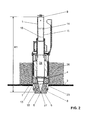
- FIG. 1 shows an inventive gowngarnitur 1, which is fixed in a conventional manner in an opening 23 of a cistern 3. Of the known cistern 3 only one area of the bottom is shown here. It is designed in a known manner so that it can absorb water 26 up to a level 22.
- An overflow pipe 11 has at an upper end an inlet opening 9, which is above the level 22 of the water 26.
- the overflow pipe 11 is liftably mounted in a housing 2 and has a known float 12 and a closing weight 21. To trigger a flush, the overflow pipe 11 is raised with an actuating device, not shown here. In of the FIG. 1 the overflow pipe 11 is shown in the raised state.
- a sealing element 4 is lifted from a valve seat 13, so that water 26 through the open valve according to the FIG. 2 can drain.
- the sealing element 4 is in communication with the overflow pipe 11 and the valve seat 13 is arranged on an outlet connection 8.
- the water 26 in this case flows through lateral openings 7 of the housing 2 in the outlet connection 8 and finally by a not shown with the outlet connection 8 in connection standing outgoing pipe in the Hopkins Remodelenden and not shown sanitary article.
- About the overflow pipe 11 can reach the outlet pipe 8 in a possible defect of the filling valve of the cistern, the rinse water so that it can not come to an overflow of the cistern.
- this flow is indicated by arrows 15.
- These arrows 15 correspond to the main flow. A portion of the water 26 of this main flow passes from below into the overflow pipe 11 and rises in this upwards.
- FIG. 2 showing a waste set without the feature essential to the invention
- the situation is shown before the complete emptying of the cistern.
- an air cone 5 is typically formed in the second half of the rinsing process, because air is sucked down through the overflow pipe 11 by the flow conditions.
- the rinse water rises in the overflow pipe 11. For example, to a level 18.
- the rinse water flows from the overflow pipe 11 in the direction of the outlet nozzle, wherein the drainage takes place at a higher speed as the drainage of the rinse water in the cistern.
- the drain fitting 1 according to the invention for a flushing cistern essentially comprises a valve seat 13, which, viewed in the flow direction, is arranged in front of an outlet opening 27.
- the valve seat 13 cooperates with a sealing element 4 of the overflow pipe 11.
- the overflow tube 11 is moved upwards, so that the contact between the sealing element 4 and the valve seat 13 is released. This position is shown in the figures. In the closed position, the sealing element 4 rests on the valve seat 13, so that no water can get out of the cistern through the outlet opening.
- the overflow tube 11 has a circumferential around a central axis M tube wall 14, an inlet opening 9 and an outlet opening 10.
- the circumferential tube wall 14 defines an interior space 24, which is accessible through said inlet opening 9 and the said outlet opening 10.
- the opening 16 has the function of reducing the height of the air column in the interior 24 of the overflow pipe 11.
- Rinse water penetrates through the opening 16 in the interior 24 in the lower region 17, wherein the area between the sealing element 4 and the valve seat 13 more or less complete filled with water, as in the FIG. 3 is shown. Due to the arrangement of the opening 16, the formation of an air cone 5 according to the FIG.
- the lower region 17 extends from the outlet opening 10 to the sealing element 4.
- the sealing element 4 is spaced from the outlet opening 10.
- the at least one opening 16 is, as already mentioned above, in this lower area 17. Thus, the at least one breakthrough between the tube outlet 10 and the sealing element. 4
- the at least one opening 16 extends completely through the pipe wall 14 of the overflow pipe 1 therethrough. Thus, an opening is provided which opens from the outside, outside the interior 24 of the overflow pipe 11, into the interior 24 of the overflow pipe 1.
- the opening 16 extends along an axis A.
- the axis A is substantially perpendicular to the central axis M of the overflow pipe 11.
- the axis A can also extend at an angle to the central axis M.
- the axis A is perpendicular to the surface through which the aperture extends.
- the at least one opening 16 is therefore a laterally arranged opening 16.
- this opening 16 runs along an axis A that is transverse to the center axis M.
- the overflow pipe 11 has in the lower region 17 via a conical portion 19 extending at least partially over the lower region.
- the lower region 17 is conical at least in sections.
- the overflow tube 11 here has a cylindrical section 20.
- the lower portion 17 is thus formed by the conical portion 19 and the cylindrical portion 20, wherein the conical portion 19 between the cylindrical portion 20 and the sealing element 4 is located.
- the at least one opening 16 is arranged here in the cylindrical section 20.
- the opening 16 may also be arranged in the conical section 19. It is also conceivable that the aperture extends from the cylindrical portion 20 into the conical portion 19.
- the conical portion 19 creates by its shape buoyancy on the overflow pipe 11 so that it can be kept open with less force. In addition, the flow in the Area positively influenced during the flushing process.
- a plurality of apertures 16 are distributed at regular intervals around the circumference in the overflow pipe 11.
- four circular openings 16, which may also be referred to as openings, are arranged.
- the four breakthroughs are spaced at an angle of 90 degrees to each other.
- the shape of the breakthrough 16 does not play a decisive role in the function. It is important that the breakthrough extends through the pipe wall 14 therethrough. But are particularly preferred breakthroughs with a circular cross-section, as well as in the FIG. 1 will be shown. But it is also conceivable that the breakthrough, for example, has a slit-like cross-section. Also, the arrangement of many small openings is conceivable.
- the outlet connection 8 has a substantially cylindrical design.
- This rounded edge 25 has a particular advantage on the water flow along the arrow 15 this particular in connection with the conical section 17th
- the overflow pipe 11 has a diameter of 28.5 mm in the present example.
- the circular openings 16 here have a diameter of 6 mm. Other dimensions are also conceivable.
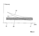
- FIG. 4 is the natural frequency E1 of the drain set without the invention essential feature and the natural frequency E2 of the drain set with the feature essential to the invention shown as a function of time.
- the time is shown on the X-axis and the frequency is shown on the Y-axis.
- the exciter frequency band EB of the running water At T0 the cistern is full and at T1 the cistern is empty.
- the exciter frequency band EB of the running water The natural frequencies decrease due to the leakage of water from the interior 14 of the overflow pipe 11 with decreasing water level in the interior 14.
- the natural frequency E1 decreases with increasing emptying so that it falls into the exciter frequency band EB, which then comes to said Gurgelgehoffschen.
- the natural frequency is determined by the height H1 of the air column, which is determined according to the FIG. 2 extends from the tip 6 of the air cone 5 up to the inlet opening 9.
- the height H2 of the air column can now be reduced.
- the characteristic of the natural frequency E2 is changed.
- the minimum natural frequency thus increases that the minimum natural frequency E2 no longer enters the excitation frequency band EB, and thus prevents the formation of a resonance.
Landscapes
- Health & Medical Sciences (AREA)
- Public Health (AREA)
- Life Sciences & Earth Sciences (AREA)
- Engineering & Computer Science (AREA)
- Hydrology & Water Resources (AREA)
- Water Supply & Treatment (AREA)
- Epidemiology (AREA)
- Devices And Processes Conducted In The Presence Of Fluids And Solid Particles (AREA)
- Sanitary Device For Flush Toilet (AREA)
- Self-Closing Valves And Venting Or Aerating Valves (AREA)
Priority Applications (2)
| Application Number | Priority Date | Filing Date | Title |
|---|---|---|---|
| EP13154398.5A EP2765249B1 (fr) | 2013-02-07 | 2013-02-07 | Garniture d'écoulement pour une chasse d'eau |
| CN201410036581.4A CN103981934A (zh) | 2013-02-07 | 2014-01-24 | 用于冲水箱的排水配件 |
Applications Claiming Priority (1)
| Application Number | Priority Date | Filing Date | Title |
|---|---|---|---|
| EP13154398.5A EP2765249B1 (fr) | 2013-02-07 | 2013-02-07 | Garniture d'écoulement pour une chasse d'eau |
Publications (2)
| Publication Number | Publication Date |
|---|---|
| EP2765249A1 true EP2765249A1 (fr) | 2014-08-13 |
| EP2765249B1 EP2765249B1 (fr) | 2018-01-03 |
Family
ID=47709967
Family Applications (1)
| Application Number | Title | Priority Date | Filing Date |
|---|---|---|---|
| EP13154398.5A Active EP2765249B1 (fr) | 2013-02-07 | 2013-02-07 | Garniture d'écoulement pour une chasse d'eau |
Country Status (2)
| Country | Link |
|---|---|
| EP (1) | EP2765249B1 (fr) |
| CN (1) | CN103981934A (fr) |
Cited By (1)
| Publication number | Priority date | Publication date | Assignee | Title |
|---|---|---|---|---|
| DE102016110694A1 (de) | 2016-06-10 | 2017-12-14 | Tece Gmbh | Ablaufventil |
Families Citing this family (3)
| Publication number | Priority date | Publication date | Assignee | Title |
|---|---|---|---|---|
| CN108018922B (zh) * | 2016-11-01 | 2021-05-18 | 科勒公司 | 坐便器入水结构 |
| CN106759750B (zh) * | 2017-01-03 | 2023-04-14 | 厦门瑞尔特卫浴科技股份有限公司 | 一种带溢流管的排水阀降噪结构 |
| EP3392418B1 (fr) * | 2017-04-19 | 2020-04-29 | Geberit International AG | Système de fixation |
Citations (5)
| Publication number | Priority date | Publication date | Assignee | Title |
|---|---|---|---|---|
| US386918A (en) * | 1888-07-31 | John demaeest | ||
| FR1191899A (fr) * | 1958-02-22 | 1959-10-22 | Pour Les Applic Des Matieres P | Perfectionnement aux réservoirs de chasse |
| EP0333652A1 (fr) * | 1988-03-16 | 1989-09-20 | Geberit AG | Dispositif pour l'amortissement du bruit d'évacuation d'eau, en particulier par le clapet d'écoulement d'un réservoir de chasse d'eau |
| CH676263A5 (fr) | 1988-07-05 | 1990-12-28 | Geberit Ag | |
| EP1854926A1 (fr) | 2006-05-11 | 2007-11-14 | Geberit Technik Ag | Dispositif d'écoulement pour réservoir de chasse d'eau |
Family Cites Families (5)
| Publication number | Priority date | Publication date | Assignee | Title |
|---|---|---|---|---|
| BE647271A (fr) * | ||||
| FR2621630B1 (fr) * | 1987-10-09 | 1989-12-15 | Pocachard Thierry | Mecanisme de commande de chasse d'eau pour wc par poussoir |
| ES2257969B1 (es) * | 2004-12-17 | 2007-08-16 | Fominaya, S.A. | Dispositivo de evacuacion para cisternas o depositos con valvula de descarga. |
| CN201024492Y (zh) * | 2007-04-17 | 2008-02-20 | 赵丕君 | 马桶节水冲水阀 |
| CN201165690Y (zh) * | 2008-01-04 | 2008-12-17 | 彭东 | 排水阀止水下盖结构 |
-
2013
- 2013-02-07 EP EP13154398.5A patent/EP2765249B1/fr active Active
-
2014
- 2014-01-24 CN CN201410036581.4A patent/CN103981934A/zh active Pending
Patent Citations (5)
| Publication number | Priority date | Publication date | Assignee | Title |
|---|---|---|---|---|
| US386918A (en) * | 1888-07-31 | John demaeest | ||
| FR1191899A (fr) * | 1958-02-22 | 1959-10-22 | Pour Les Applic Des Matieres P | Perfectionnement aux réservoirs de chasse |
| EP0333652A1 (fr) * | 1988-03-16 | 1989-09-20 | Geberit AG | Dispositif pour l'amortissement du bruit d'évacuation d'eau, en particulier par le clapet d'écoulement d'un réservoir de chasse d'eau |
| CH676263A5 (fr) | 1988-07-05 | 1990-12-28 | Geberit Ag | |
| EP1854926A1 (fr) | 2006-05-11 | 2007-11-14 | Geberit Technik Ag | Dispositif d'écoulement pour réservoir de chasse d'eau |
Cited By (3)
| Publication number | Priority date | Publication date | Assignee | Title |
|---|---|---|---|---|
| DE102016110694A1 (de) | 2016-06-10 | 2017-12-14 | Tece Gmbh | Ablaufventil |
| WO2017212068A2 (fr) | 2016-06-10 | 2017-12-14 | Tece Gmbh | Soupape de vidange |
| WO2017212068A3 (fr) * | 2016-06-10 | 2018-02-01 | Tece Gmbh | Soupape de vidange |
Also Published As
| Publication number | Publication date |
|---|---|
| EP2765249B1 (fr) | 2018-01-03 |
| CN103981934A (zh) | 2014-08-13 |
Similar Documents
| Publication | Publication Date | Title |
|---|---|---|
| EP2765249B1 (fr) | Garniture d'écoulement pour une chasse d'eau | |
| EP3469158B1 (fr) | Soupape de vidange | |
| DE102009010862B4 (de) | Geruchsverschluss für ein Vakuumtoilettenabflusssystem, Ablaufvorrichtung, Vakuumtoilettensystem sowie Flugzeug mit einem solchen Vakuumtoilettensystem | |
| EP2508686B1 (fr) | Installation de retenue pour l'eau de précipitation et les eaux usées | |
| DE202014007392U1 (de) | Wasserablauf mit Mehrfachsiphon-Geruchsverschluss | |
| EP1854926B1 (fr) | Dispositif d'écoulement pour réservoir de chasse d'eau | |
| EP2369088B1 (fr) | Dispositif destiné au drainage des eaux pluviales de toit | |
| EP2871294B1 (fr) | Garniture d'entrée pour une chasse d'eau | |
| EP2700759A1 (fr) | Garniture d'entrée pour une chasse dýeau | |
| EP1449968A2 (fr) | Réservoir d'eau pour une toilette et toilette correspondante | |
| EP2829666B1 (fr) | Garniture d'entrée pour une chasse d'eau | |
| EP1484453B1 (fr) | Dispositif de vidange et de trop-plein pour appareils sanitaires | |
| EP2505727B1 (fr) | Clapet de sortie pour une chasse d'eau | |
| EP3321431B1 (fr) | Raccord fileté d'évacuation | |
| EP2995731B1 (fr) | Dispositif d'écoulement d'eau doté d'un système de blocage d'odeur à siphons multiples | |
| DE102007004833B4 (de) | Verschlussvorrichtung für Vakuumurinale in Luftfahrzeugen | |
| EP3538716B1 (fr) | Raccord fileté d'évacuation | |
| CH711775B1 (de) | Überlauf für eine Spüle. | |
| EP4227469B1 (fr) | Système de rinçage | |
| DE688902C (de) | Abtrittspuelvorrichtung mit Bodenventil | |
| EP0757135A1 (fr) | Réservoir de chasse d'eau | |
| EP3321432B1 (fr) | Raccord fileté d'évacuation | |
| WO1997022761A1 (fr) | Dispositif pour un reservoir de chasse d'eau | |
| EP3321434B1 (fr) | Raccord fileté d'évacuation | |
| EP3848519A1 (fr) | Agencement sanitaire comprenant un urinoir et un siphon d'aspiration à relier ou à raccorder à l'urinoir et une buse de rincage |
Legal Events
| Date | Code | Title | Description |
|---|---|---|---|
| PUAI | Public reference made under article 153(3) epc to a published international application that has entered the european phase |
Free format text: ORIGINAL CODE: 0009012 |
|
| 17P | Request for examination filed |
Effective date: 20130207 |
|
| AK | Designated contracting states |
Kind code of ref document: A1 Designated state(s): AL AT BE BG CH CY CZ DE DK EE ES FI FR GB GR HR HU IE IS IT LI LT LU LV MC MK MT NL NO PL PT RO RS SE SI SK SM TR |
|
| AX | Request for extension of the european patent |
Extension state: BA ME |
|
| R17P | Request for examination filed (corrected) |
Effective date: 20141220 |
|
| RBV | Designated contracting states (corrected) |
Designated state(s): AL AT BE BG CH CY CZ DE DK EE ES FI FR GB GR HR HU IE IS IT LI LT LU LV MC MK MT NL NO PL PT RO RS SE SI SK SM TR |
|
| 17Q | First examination report despatched |
Effective date: 20160729 |
|
| GRAP | Despatch of communication of intention to grant a patent |
Free format text: ORIGINAL CODE: EPIDOSNIGR1 |
|
| INTG | Intention to grant announced |
Effective date: 20170721 |
|
| GRAS | Grant fee paid |
Free format text: ORIGINAL CODE: EPIDOSNIGR3 |
|
| GRAA | (expected) grant |
Free format text: ORIGINAL CODE: 0009210 |
|
| AK | Designated contracting states |
Kind code of ref document: B1 Designated state(s): AL AT BE BG CH CY CZ DE DK EE ES FI FR GB GR HR HU IE IS IT LI LT LU LV MC MK MT NL NO PL PT RO RS SE SI SK SM TR |
|
| REG | Reference to a national code |
Ref country code: GB Ref legal event code: FG4D Free format text: NOT ENGLISH |
|
| REG | Reference to a national code |
Ref country code: CH Ref legal event code: EP Ref country code: AT Ref legal event code: REF Ref document number: 960409 Country of ref document: AT Kind code of ref document: T Effective date: 20180115 |
|
| REG | Reference to a national code |
Ref country code: IE Ref legal event code: FG4D Free format text: LANGUAGE OF EP DOCUMENT: GERMAN |
|
| REG | Reference to a national code |
Ref country code: CH Ref legal event code: NV Representative=s name: ISLER AND PEDRAZZINI AG, CH |
|
| REG | Reference to a national code |
Ref country code: DE Ref legal event code: R096 Ref document number: 502013009156 Country of ref document: DE |
|
| REG | Reference to a national code |
Ref country code: FR Ref legal event code: PLFP Year of fee payment: 6 |
|
| REG | Reference to a national code |
Ref country code: NL Ref legal event code: MP Effective date: 20180103 |
|
| REG | Reference to a national code |
Ref country code: LT Ref legal event code: MG4D |
|
| REG | Reference to a national code |
Ref country code: NO Ref legal event code: T2 Effective date: 20180103 |
|
| PG25 | Lapsed in a contracting state [announced via postgrant information from national office to epo] |
Ref country code: NL Free format text: LAPSE BECAUSE OF FAILURE TO SUBMIT A TRANSLATION OF THE DESCRIPTION OR TO PAY THE FEE WITHIN THE PRESCRIBED TIME-LIMIT Effective date: 20180103 |
|
| PG25 | Lapsed in a contracting state [announced via postgrant information from national office to epo] |
Ref country code: LT Free format text: LAPSE BECAUSE OF FAILURE TO SUBMIT A TRANSLATION OF THE DESCRIPTION OR TO PAY THE FEE WITHIN THE PRESCRIBED TIME-LIMIT Effective date: 20180103 Ref country code: ES Free format text: LAPSE BECAUSE OF FAILURE TO SUBMIT A TRANSLATION OF THE DESCRIPTION OR TO PAY THE FEE WITHIN THE PRESCRIBED TIME-LIMIT Effective date: 20180103 Ref country code: HR Free format text: LAPSE BECAUSE OF FAILURE TO SUBMIT A TRANSLATION OF THE DESCRIPTION OR TO PAY THE FEE WITHIN THE PRESCRIBED TIME-LIMIT Effective date: 20180103 Ref country code: FI Free format text: LAPSE BECAUSE OF FAILURE TO SUBMIT A TRANSLATION OF THE DESCRIPTION OR TO PAY THE FEE WITHIN THE PRESCRIBED TIME-LIMIT Effective date: 20180103 Ref country code: CY Free format text: LAPSE BECAUSE OF FAILURE TO SUBMIT A TRANSLATION OF THE DESCRIPTION OR TO PAY THE FEE WITHIN THE PRESCRIBED TIME-LIMIT Effective date: 20180103 |
|
| PG25 | Lapsed in a contracting state [announced via postgrant information from national office to epo] |
Ref country code: LV Free format text: LAPSE BECAUSE OF FAILURE TO SUBMIT A TRANSLATION OF THE DESCRIPTION OR TO PAY THE FEE WITHIN THE PRESCRIBED TIME-LIMIT Effective date: 20180103 Ref country code: SE Free format text: LAPSE BECAUSE OF FAILURE TO SUBMIT A TRANSLATION OF THE DESCRIPTION OR TO PAY THE FEE WITHIN THE PRESCRIBED TIME-LIMIT Effective date: 20180103 Ref country code: RS Free format text: LAPSE BECAUSE OF FAILURE TO SUBMIT A TRANSLATION OF THE DESCRIPTION OR TO PAY THE FEE WITHIN THE PRESCRIBED TIME-LIMIT Effective date: 20180103 Ref country code: PL Free format text: LAPSE BECAUSE OF FAILURE TO SUBMIT A TRANSLATION OF THE DESCRIPTION OR TO PAY THE FEE WITHIN THE PRESCRIBED TIME-LIMIT Effective date: 20180103 Ref country code: GR Free format text: LAPSE BECAUSE OF FAILURE TO SUBMIT A TRANSLATION OF THE DESCRIPTION OR TO PAY THE FEE WITHIN THE PRESCRIBED TIME-LIMIT Effective date: 20180404 Ref country code: IS Free format text: LAPSE BECAUSE OF FAILURE TO SUBMIT A TRANSLATION OF THE DESCRIPTION OR TO PAY THE FEE WITHIN THE PRESCRIBED TIME-LIMIT Effective date: 20180503 Ref country code: BG Free format text: LAPSE BECAUSE OF FAILURE TO SUBMIT A TRANSLATION OF THE DESCRIPTION OR TO PAY THE FEE WITHIN THE PRESCRIBED TIME-LIMIT Effective date: 20180403 |
|
| PG25 | Lapsed in a contracting state [announced via postgrant information from national office to epo] |
Ref country code: MT Free format text: LAPSE BECAUSE OF FAILURE TO SUBMIT A TRANSLATION OF THE DESCRIPTION OR TO PAY THE FEE WITHIN THE PRESCRIBED TIME-LIMIT Effective date: 20180103 |
|
| REG | Reference to a national code |
Ref country code: DE Ref legal event code: R097 Ref document number: 502013009156 Country of ref document: DE |
|
| PG25 | Lapsed in a contracting state [announced via postgrant information from national office to epo] |
Ref country code: AL Free format text: LAPSE BECAUSE OF FAILURE TO SUBMIT A TRANSLATION OF THE DESCRIPTION OR TO PAY THE FEE WITHIN THE PRESCRIBED TIME-LIMIT Effective date: 20180103 Ref country code: MC Free format text: LAPSE BECAUSE OF FAILURE TO SUBMIT A TRANSLATION OF THE DESCRIPTION OR TO PAY THE FEE WITHIN THE PRESCRIBED TIME-LIMIT Effective date: 20180103 Ref country code: EE Free format text: LAPSE BECAUSE OF FAILURE TO SUBMIT A TRANSLATION OF THE DESCRIPTION OR TO PAY THE FEE WITHIN THE PRESCRIBED TIME-LIMIT Effective date: 20180103 Ref country code: RO Free format text: LAPSE BECAUSE OF FAILURE TO SUBMIT A TRANSLATION OF THE DESCRIPTION OR TO PAY THE FEE WITHIN THE PRESCRIBED TIME-LIMIT Effective date: 20180103 |
|
| PLBE | No opposition filed within time limit |
Free format text: ORIGINAL CODE: 0009261 |
|
| STAA | Information on the status of an ep patent application or granted ep patent |
Free format text: STATUS: NO OPPOSITION FILED WITHIN TIME LIMIT |
|
| REG | Reference to a national code |
Ref country code: IE Ref legal event code: MM4A |
|
| REG | Reference to a national code |
Ref country code: BE Ref legal event code: MM Effective date: 20180228 |
|
| PG25 | Lapsed in a contracting state [announced via postgrant information from national office to epo] |
Ref country code: SM Free format text: LAPSE BECAUSE OF FAILURE TO SUBMIT A TRANSLATION OF THE DESCRIPTION OR TO PAY THE FEE WITHIN THE PRESCRIBED TIME-LIMIT Effective date: 20180103 Ref country code: SK Free format text: LAPSE BECAUSE OF FAILURE TO SUBMIT A TRANSLATION OF THE DESCRIPTION OR TO PAY THE FEE WITHIN THE PRESCRIBED TIME-LIMIT Effective date: 20180103 Ref country code: CZ Free format text: LAPSE BECAUSE OF FAILURE TO SUBMIT A TRANSLATION OF THE DESCRIPTION OR TO PAY THE FEE WITHIN THE PRESCRIBED TIME-LIMIT Effective date: 20180103 Ref country code: LU Free format text: LAPSE BECAUSE OF NON-PAYMENT OF DUE FEES Effective date: 20180207 Ref country code: DK Free format text: LAPSE BECAUSE OF FAILURE TO SUBMIT A TRANSLATION OF THE DESCRIPTION OR TO PAY THE FEE WITHIN THE PRESCRIBED TIME-LIMIT Effective date: 20180103 |
|
| 26N | No opposition filed |
Effective date: 20181005 |
|
| PG25 | Lapsed in a contracting state [announced via postgrant information from national office to epo] |
Ref country code: IE Free format text: LAPSE BECAUSE OF NON-PAYMENT OF DUE FEES Effective date: 20180207 |
|
| PG25 | Lapsed in a contracting state [announced via postgrant information from national office to epo] |
Ref country code: SI Free format text: LAPSE BECAUSE OF FAILURE TO SUBMIT A TRANSLATION OF THE DESCRIPTION OR TO PAY THE FEE WITHIN THE PRESCRIBED TIME-LIMIT Effective date: 20180103 Ref country code: BE Free format text: LAPSE BECAUSE OF NON-PAYMENT OF DUE FEES Effective date: 20180228 |
|
| PG25 | Lapsed in a contracting state [announced via postgrant information from national office to epo] |
Ref country code: TR Free format text: LAPSE BECAUSE OF FAILURE TO SUBMIT A TRANSLATION OF THE DESCRIPTION OR TO PAY THE FEE WITHIN THE PRESCRIBED TIME-LIMIT Effective date: 20180103 |
|
| PG25 | Lapsed in a contracting state [announced via postgrant information from national office to epo] |
Ref country code: HU Free format text: LAPSE BECAUSE OF FAILURE TO SUBMIT A TRANSLATION OF THE DESCRIPTION OR TO PAY THE FEE WITHIN THE PRESCRIBED TIME-LIMIT; INVALID AB INITIO Effective date: 20130207 Ref country code: PT Free format text: LAPSE BECAUSE OF FAILURE TO SUBMIT A TRANSLATION OF THE DESCRIPTION OR TO PAY THE FEE WITHIN THE PRESCRIBED TIME-LIMIT Effective date: 20180103 |
|
| PG25 | Lapsed in a contracting state [announced via postgrant information from national office to epo] |
Ref country code: MK Free format text: LAPSE BECAUSE OF NON-PAYMENT OF DUE FEES Effective date: 20180103 |
|
| PGFP | Annual fee paid to national office [announced via postgrant information from national office to epo] |
Ref country code: CH Payment date: 20220211 Year of fee payment: 10 Ref country code: AT Payment date: 20220217 Year of fee payment: 10 |
|
| PGFP | Annual fee paid to national office [announced via postgrant information from national office to epo] |
Ref country code: NO Payment date: 20220218 Year of fee payment: 10 |
|
| P01 | Opt-out of the competence of the unified patent court (upc) registered |
Effective date: 20230516 |
|
| REG | Reference to a national code |
Ref country code: NO Ref legal event code: MMEP |
|
| REG | Reference to a national code |
Ref country code: CH Ref legal event code: PL |
|
| REG | Reference to a national code |
Ref country code: AT Ref legal event code: MM01 Ref document number: 960409 Country of ref document: AT Kind code of ref document: T Effective date: 20230207 |
|
| PG25 | Lapsed in a contracting state [announced via postgrant information from national office to epo] |
Ref country code: NO Free format text: LAPSE BECAUSE OF NON-PAYMENT OF DUE FEES Effective date: 20230228 Ref country code: LI Free format text: LAPSE BECAUSE OF NON-PAYMENT OF DUE FEES Effective date: 20230228 Ref country code: CH Free format text: LAPSE BECAUSE OF NON-PAYMENT OF DUE FEES Effective date: 20230228 Ref country code: AT Free format text: LAPSE BECAUSE OF NON-PAYMENT OF DUE FEES Effective date: 20230207 |
|
| PGFP | Annual fee paid to national office [announced via postgrant information from national office to epo] |
Ref country code: DE Payment date: 20250218 Year of fee payment: 13 |
|
| PGFP | Annual fee paid to national office [announced via postgrant information from national office to epo] |
Ref country code: FR Payment date: 20250221 Year of fee payment: 13 |
|
| PGFP | Annual fee paid to national office [announced via postgrant information from national office to epo] |
Ref country code: IT Payment date: 20250221 Year of fee payment: 13 Ref country code: GB Payment date: 20250219 Year of fee payment: 13 |