EP1854926A1 - Ablaufgarnitur für einen Spülkasten - Google Patents
Ablaufgarnitur für einen Spülkasten Download PDFInfo
- Publication number
- EP1854926A1 EP1854926A1 EP06405197A EP06405197A EP1854926A1 EP 1854926 A1 EP1854926 A1 EP 1854926A1 EP 06405197 A EP06405197 A EP 06405197A EP 06405197 A EP06405197 A EP 06405197A EP 1854926 A1 EP1854926 A1 EP 1854926A1
- Authority
- EP
- European Patent Office
- Prior art keywords
- overflow pipe
- nozzle
- separating nozzle
- fitting according
- drain fitting
- Prior art date
- Legal status (The legal status is an assumption and is not a legal conclusion. Google has not performed a legal analysis and makes no representation as to the accuracy of the status listed.)
- Granted
Links
Images


Classifications
-
- E—FIXED CONSTRUCTIONS
- E03—WATER SUPPLY; SEWERAGE
- E03D—WATER-CLOSETS OR URINALS WITH FLUSHING DEVICES; FLUSHING VALVES THEREFOR
- E03D1/00—Water flushing devices with cisterns ; Setting up a range of flushing devices or water-closets; Combinations of several flushing devices
- E03D1/30—Valves for high or low level cisterns; Their arrangement ; Flushing mechanisms in the cistern, optionally with provisions for a pre-or a post- flushing and for cutting off the flushing mechanism in case of leakage
- E03D1/34—Flushing valves for outlets; Arrangement of outlet valves
Definitions
- the invention relates to a drain fitting for a cistern, having a valve seat, which is arranged upstream of an outlet opening seen in the flow direction, with a cooperating with this valve seat sealing element of a valve tube, which can be moved to trigger a flush up.
- flushing can be triggered by lifting the overflow pipe.
- the lifting of the overflow pipe is usually carried out with an actuating device having, for example, a button.
- an actuating device having, for example, a button.
- the water stored in the cistern passes through gravity through the outlet opening in a drain pipe and finally into a toilet bowl or urinal.
- the purge is interrupted by the overflow pipe falling onto the valve seat.
- Such a flushing process is associated with noises that have different causes.
- the invention has for its object to provide a drain fitting of the type mentioned, in which the flushing noise are further reduced.
- the object is achieved in a generic waste set in that below the sealing element, a separation nozzle is arranged, which prevents a shear layer forming a shear layer between the outer main flow and the inner overflow flow.
- the invention is based on the finding that, after the triggering of a flushing by a congestion in the drainage pipe, water passes from below into the overflow pipe and initially rises in the overflow pipe and then flows downwards more rapidly than the main flow as an overflow stream into the drainage pipe.
- a shear layer with turbulent vortex shedding forms between the main flow and the overflow flow.
- These vortices produce highly pulsating pressures in the purge system.
- the pressure pulsations can couple with the air movements arising in the overflow pipe and cause an acoustic resonance in the overflow pipe. If such a coupling occurs, the noise level in the overflow pipe increases considerably.
- the separation nozzle is formed sleeve-shaped. This allows a particularly simple and yet effective production of the separation nozzle.
- a sleeve-shaped separating nozzle can for example be very easily arranged on a guide nozzle, which is located at the lower end of the overflow pipe.
- the separation nozzle extends into a discharge pipe arranged downstream of the outlet opening.
- a particularly effective noise reduction results when, according to a development of the invention, the separation nozzle has a length which is greater by a multiple than an inner diameter of the separation nozzle.
- the shear layer between the main flow and the overflow flow and thus the formation of a turbulent vortex shedding can be particularly effectively avoided.
- the separation nozzle is arranged concentrically to the overflow pipe and that a passage for the rinse water is provided between the separation nozzle and the overflow pipe.
- the separation nozzle may be connected to the lower end of the overflow pipe.
- the separation nozzle is a separate part and inserted from above into the overflow pipe.
- valve tube has at its lower end a conically tapered guide nozzle and that the separation nozzle is seated in this guide nozzle. This allows a particularly simple and cost-effective production as well as assembly.
- the separating nozzle is concentrically mounted in a discharge pipe.
- the separating nozzle can be fastened by webs with a circumferential wall of the outlet pipe.
- the separation nozzle can be formed, for example, on the outlet pipe.
- the separation nozzle extends up into the mouth of the overflow pipe.
- the separation nozzle preferably formed sleeve-shaped. Its outer diameter is smaller than the outer diameter of the overflow pipe at the lower end.
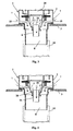
- FIG. 1 shows an inventive waste fitting 1, which is fixed in a conventional manner in an opening 23 of a cistern 3. Of the known cistern 3 only one area of the bottom is shown here. It is designed in a known manner so that it can absorb water 26 up to a level 22.
- An overflow pipe 11 has at an upper end an inlet opening 9, which is above the level 22 of the water 26.
- the overflow pipe 11 is liftably mounted in a housing 2 and has a known float 12.
- a sealing element 4 is lifted off a valve seat 13, so that water 26 can flow away through the opened valve according to FIG.
- the water 26 in this case flows through lateral openings 7 of the housing 2 in an outlet connection 8 and finally through a discharge pipe 10 in the rinsing and not shown sanitary article.
- this flow is indicated by arrows 15.
- These arrows 15 correspond to the main flow. A portion of the water 26 of this main flow passes from below into the overflow pipe 11 and rises in this upwards. This is indicated in FIG.
- FIG. 6 shows a cistern according to the prior art, wherein the overflow pipe 11 is lifted off and thus the valve is opened.
- a water column 20 has formed shortly after the Spülausaims in the overflow pipe 11.
- the water of this water column 20 flows according to the arrow 16 downwards and faster than the main flow.
- a shear layer S is formed, which is indicated by two lines and according to the double arrow 21 has an inner diameter.
- This shear layer S is essentially approximately circular cylindrical and extends approximately coaxially to the outlet connection 8.
- turbulent vortex separations form, which generate pulsating pressures in the flushing system. This causes an acoustic resonance in the overflow pipe 11 and leads to noises, in particular gurgling noises.
- a separation nozzle 6 is arranged, which has a continuous inner channel 25.
- the separation nozzle 6 has substantially the shape of a circular cylindrical cross-section sleeve, which extends from a guide nozzle 5 downwards.
- the separation nozzle 6 is inserted from above into the overflow pipe 11 and held with hook-shaped holding means 24 in the guide nozzle 5.
- These holding means 24 are formed so that between the separating nozzle 6 and the guide nozzle 5 more passages 27 are made, as Figure 1 shows.
- the separation nozzle 6 is movably held in the guide nozzle 5 in this embodiment.
- the guide nozzle 6a via a plurality of laterally projecting webs 28 fixed to the Guiding nozzle 5 connected.
- the separation nozzle 6 has according to Figure 2 has a diameter D and a length L, wherein the length L is substantially larger and preferably greater by a multiple than the diameter.
- FIG. 3 shows the flow conditions after a rinsing release and thus when the overflow pipe 11 is raised.
- the main flow is again indicated by arrows 15.
- In the channel 29 of the overflow pipe 11 is water, which flows in the direction of arrow 16 and in addition in the directions of arrows 17 down from the overflow pipe 11.
- the separation nozzle 6 is located where previously according to Figure 6 between the main flow and the overflow a shear layer S was present. The separation nozzle 6 thus prevents the formation of turbulent vortex shedding, which previously led to a noise.
- a separation nozzle 6b is provided, which is fixed via webs 18 coaxially in the outlet connection 8 at this.
- the separation nozzle 6b extends from the webs 18 upwards in the guide nozzle 5, as Figure 5 shows. Also, the separation nozzle 6b extends from the webs 18 down.
- the water of the main flow passes on the outside of the separation nozzle 6b according to the arrows 19 down and is separated in the region of the separation nozzle 6b of the overflow, which flows according to arrow 16 through the channel of the separation nozzle 6b.
- the separation nozzle 6b is located in a region in which otherwise the above-mentioned shear layer would form. When lifting the overflow pipe 11, however, the separation nozzle 6b remains in the position shown and is not raised.
Landscapes
- Health & Medical Sciences (AREA)
- Life Sciences & Earth Sciences (AREA)
- Engineering & Computer Science (AREA)
- Hydrology & Water Resources (AREA)
- Public Health (AREA)
- Water Supply & Treatment (AREA)
- Sink And Installation For Waste Water (AREA)
Abstract
Description
- Die Erfindung betrifft eine Ablaufgarnitur für einen Spülkasten, mit einem Ventilsitz, der in Strömungsrichtung gesehen vor einer Auslauföffnung angeordnet ist, mit einem mit diesem Ventilsitz zusammenarbeitenden Dichtelement eines Ventilrohres, das zum Auslösen einer Spülung nach oben bewegt werden kann.
- Bei den allgemein bekannten Ablaufgarnituren der genannten Art kann eine Spülung durch Anheben des Überlaufrohres ausgelöst werden. Das Anheben des Überlaufrohres erfolgt in der Regel mit einer Betätigungsvorrichtung, die beispielsweise eine Taste aufweist. Nach der Auslösung einer Spülung gelangt das im Spülkasten gelagerte Wasser infolge der Gravitation durch die Auslauföffnung in ein Ablaufrohr und schliesslich in eine WC-Schüssel oder in ein Urinal. Die Spülung wird unterbrochen, indem das Überlaufrohr auf den Ventilsitz fällt. Ein solcher Spülvorgang ist mit Geräuschen verbunden, die unterschiedliche Ursachen besitzen. Um diese Geräusche zu vermindern, ist bei der Ablaufgarnitur nach der
CH 676 263 A - Bei der Ablaufgarnitur nach der
DE 199 31 203 A wird für den gleichen Zweck vorgeschlagen, dass oberhalb des Dichtelementes bzw. am Ventilteller am Überlaufrohr ein Strömungsabweiser angeordnet wird. Damit soll vermieden werden, dass das Dichtelement vor der Spülunterbrechung unzulässig beschleunigt wird. - Mit den genannten Massnahmen kann lediglich das Geräusch vermindert werden, dass durch den Aufschlag des Überlaufrohres bzw. des Ventiltellers auf den Ventilsitz erzeugt wird. Die übrigen Geräuschquellen werden aber hierbei nicht beeinflusst.
- Der Erfindung liegt die Aufgabe zugrunde, eine Ablaufgarnitur der genannten Art zu schaffen, bei welcher die Spülgeräusche weiter vermindert sind.
- Die Aufgabe ist bei einer gattungsgemässen Ablaufgarnitur dadurch gelöst, dass unterhalb des Dichtelementes eine Trenndüse angeordnet ist, die bei einem Spülvorgang eine Scherschichtbildung zwischen der äusseren Hauptströmung und der inneren Überlaufströmung verhindert. Der Erfindung liegt die Erkenntnis zugrunde, dass nach der Auslösung einer Spülung durch einen Stau im Ablaufrohr Wasser von unten in das Überlaufrohr gelangt und in diesem zunächst hochsteigt und dann schneller als die Hauptströmung als Überlaufströmung nach unten in das Ablaufrohr ausströmt. Hierbei bildet sich zwischen der Hauptströmung und der Überlaufströmung eine Scherschicht mit turbulenter Wirbelablösung. Diese Wirbel erzeugen stark pulsierende Drücke im Spülsystem. Die Druckpulsationen können mit den im Überlaufrohr entstehenden Luftbewegungen kuppeln und eine akustische Resonanz im Überlaufrohr verursachen. Tritt eine solche Kuppelung auf, erhöht sich das Lärmniveau im Überlaufrohr erheblich.
- Bei der erfindungsgemässen Ablaufgarnitur wird das Entstehen der genannten Wirbel mit einer Trenndüse weitgehend verhindert. Dadurch können vor allem die kurzzeitigen Geräusche beim Öffnen des Ventils wesentlich vermindert werden. Diese Geräusche wurden bisher als Gurgeln wahrgenommen und konnten mit den oben erwähnten bekannten Ablaufgarnituren im Wesentlichen nicht beeinflusst werden.
- Nach einer Weiterbildung der Erfindung ist vorgesehen, dass die Trenndüse hülsenförmig ausgebildet ist. Dies ermöglicht eine besonders einfache und dennoch wirksame Herstellung der Trenndüse. Eine solche hülsenförmige Trenndüse kann beispielsweise sehr einfach an einer Führungsdüse angeordnet werden, die sich am unteren Ende des Überlaufrohres befindet.
- Die Trenndüse erstreckt sich in ein nach der Auslauföffnung angeordnetes Abgangsrohr. Eine besonders wirksame Geräuschminderung ergibt sich dann, wenn gemäss einer Weiterbildung der Erfindung die Trenndüse ein Länge aufweist, die um ein Mehrfaches grösser ist als ein Innendurchmesser der Trenndüse. Damit kann die Scherschicht zwischen der Hauptströmung und der Überlaufströmung und somit die Entstehung einer turbulenten Wirbelablösung besonders wirksam vermieden werden.
- Nach einer Weiterbildung der Erfindung ist vorgesehen, dass die Trenndüse konzentrisch zum Überlaufrohr angeordnet ist und dass zwischen der Trenndüse und dem Überlaufrohr ein Durchgang für das Spülwasser vorgesehen ist. Beispielsweise kann die Trenndüse mit dem unteren Ende des Überlaufrohres verbunden sein. Dadurch kann das im Überlaufrohr vorhandene Wasser und auch nachfolgend die Luft im Wesentlichen wie bisher ungehindert abströmen. Vorzugsweise ist die Trenndüse ein separates Teil und von oben in das Überlaufrohr eingesetzt.
- Nach einer Variante ist vorgesehen, dass das Ventilrohr an seinem unteren Ende eine konisch verjüngte Führungsdüse aufweist und dass die Trenndüse in dieser Führungsdüse sitzt. Dies ermöglicht eine besonders einfache und kostengünstige Herstellung als auch Montage.
- Gemäss einer Weiterbildung der Erfindung ist die Trenndüse konzentrisch in einem Abgangsrohr befestigt. Beispielsweise kann die Trenndüse über Stege mit einer umlaufenden Wandung des Abgangsrohres befestigt sein. Beim Hochziehen des Überlaufrohres verbleibt somit die Trenndüse fest im Abgangsrohr. Die Trenndüse kann beispielsweise am Abgangsrohr angeformt sein. Vorzugsweise erstreckt sich die Trenndüse nach oben in die Mündung des Überlaufrohres. Auch in diesem Fall ist die Trenndüse vorzugsweise hülsenförmig ausgebildet. Ihr Aussendurchmesser ist kleiner als der Aussendurchmesser des Überlaufrohres am unteren Ende.
- Weitere vorteilhafte Merkmale ergeben sich aus den abhängigen Patentansprüchen, der nachfolgenden Beschreibung sowie der Zeichnung.
- Ausführungsbeispiele der Erfindung werden nachfolgend anhand der Zeichnung näher erläutert. Es zeigen:
- Figur 1
- schematisch ein Schnitt durch eine erfindungsgemässe Ablaufgarnitur in der Ausgangsstellung,
- Figur 2
- ein Schnitt gemäss Figur 1, jedoch nach Auslösung einer Spülung,
- Figur 3
- schematisch ein Vertikalschnitt durch einen unteren Teil der erfindungsgemässen Ablaufgarnitur zur Erläuterung der Strömungsverhältnisse,
- Figur 4
- ein Schnitt gemäss Figur 3, jedoch mit einer Ausführung gemäss einer Variante,
- Figur 5
- ein vertikaler Schnitt durch ein unteres Ende einer erfindungsgemässen Ablaufgarnitur gemäss einer weiteren Variante und
- Figur 6
- schematisch ein Schnitt durch einen Spülkasten mit einer Ablaufgarnitur nach dem Stand der Technik zur Erläuterung der Strömungsverhältnisse.
- Die Figur 1 zeigt eine erfindungsgemässe Ablaufgarnitur 1, die in an sich bekannter Weise in einer Öffnung 23 eines Spülkastens 3 befestigt ist. Von dem an sich bekannten Spülkasten 3 ist hier lediglich ein Bereich des Bodens gezeigt. Er ist in bekannter Weise so ausgebildet, dass er Wasser 26 bis zu einem Niveau 22 aufnehmen kann. Ein Überlaufrohr 11 besitzt an einem oberen Ende eine Eintrittsöffnung 9, die über dem Niveau 22 des Wassers 26 liegt. Das Überlaufrohr 11 ist anhebbar in einem Gehäuse 2 gelagert und besitzt einen an sich bekannten Schwimmer 12. Zur Auslösung einer Spülung wird das Überlaufrohr 11 mit einer hier nicht gezeigten Betätigungsvorrichtung angehoben. Hierbei wird ein Dichtungselement 4 von einem Ventilsitz 13 abgehoben, so dass Wasser 26 durch das geöffnete Ventil gemäss der Figur 2 abfliessen kann. Das Wasser 26 strömt hierbei durch seitliche Öffnungen 7 des Gehäuses 2 in einen Auslaufstutzen 8 und schliesslich durch ein Abgangsrohr 10 in den auszuspülenden und hier nicht gezeigten Sanitärartikel.
- In der Figur 2 ist diese Strömung mit Pfeilen 15 angedeutet. Diese Pfeile 15 entsprechen der Hauptströmung. Ein Teil des Wassers 26 dieser Hauptströmung gelangt von unten in das Überlaufrohr 11 und steigt in diesem nach oben. Dies ist in der Figur 6 angedeutet.
- Die Figur 6 zeigt einen Spülkasten nach dem Stand der Technik, wobei das Überlaufrohr 11 abgehoben und damit das Ventil geöffnet ist. Wie ersichtlich, hat sich kurz nach der Spülauslösung im Überlaufrohr 11 eine Wassersäule 20 gebildet. Das Wasser dieser Wassersäule 20 strömt gemäss dem Pfeil 16 nach unten und zwar schneller als die Hauptströmung. Zwischen der Hauptströmung gemäss den Pfeilen 15 und der Überlaufströmung gemäss Pfeil 16 bildet sich eine Scherschicht S, die mit zwei Linien angedeutet ist und gemäss dem Doppelpfeil 21 einen Innendurchmesser besitzt. Diese Scherschicht S ist im Wesentlichen etwa kreiszylindrisch und verläuft etwa koaxial zum Auslaufstutzen 8. In dieser Scherschicht S bilden sich turbulente Wirbelablösungen, die pulsierende Drücke im Spülsystem erzeugen. Dies bewirkt eine akustische Resonanz im Überlaufrohr 11 und führt zu Geräuschen, insbesondere zu gurgelnden Geräuschen.
- Um diese turbulenten Wirbelablösungen erfindungsgemäss zu vermeiden, ist gemäss den Figuren 1 bis 3 am unteren Ende des Überlaufrohres 11 eine Trenndüse 6 angeordnet, die einen durchgehenden inneren Kanal 25 aufweist. Die Trenndüse 6 hat im Wesentlichen die Form einer im Querschnitt kreisförmigen zylindrischen Hülse, die sich von einer Führungsdüse 5 nach unten erstreckt. Die Trenndüse 6 ist von oben in das Überlaufrohr 11 eingesetzt und mit hakenförmigen Haltemitteln 24 in der Führungsdüse 5 gehalten. Diese Haltemittel 24 sind so ausgebildet, dass zwischen der Trenndüse 6 und der Führungsdüse 5 mehrere Durchgänge 27 bestehen, wie die Figur 1 zeigt. Die Trenndüse 6 ist bei dieser Ausführung beweglich in der Führungsdüse 5 gehalten. Nach der in Figur 4 gezeigten Variante ist die Führungsdüse 6a über mehrere seitlich vorragende Stege 28 fest mit der Führungsdüse 5 verbunden. Die Trenndüse 6 besitzt gemäss Figur 2 einen Durchmesser D und eine Länge L, wobei die Länge L wesentlich grösser und vorzugsweise um ein Mehrfaches grösser ist als der Durchmesser.
- Die Figur 3 zeigt die Strömungsverhältnisse nach einer Spülauslösung und somit bei angehobenem Überlaufrohr 11. Die Hauptströmung ist wiederum mit Pfeilen 15 angedeutet. Im Kanal 29 des Überlaufrohres 11 befindet sich Wasser, das in Richtung des Pfeiles 16 und zusätzlich in den Richtungen der Pfeile 17 nach unten aus dem Überlaufrohr 11 ausströmt. Die Überlaufströmung hat zur Folge, dass gemäss Figur 2, in Richtung der Pfeile 14, Luft durch die Eintrittsöffnung 9 in das Überlaufrohr 11 strömt. Die Trenndüse 6 befindet sich dort, wo bisher gemäss Figur 6 zwischen der Hauptströmung und der Überlaufströmung eine Scherschicht S vorhanden war. Die Trenndüse 6 verhindert damit die Bildung turbulenter Wirbelablösungen, die bisher zu einer Geräuschentwicklung führten. Ist der Kanal 29 entleert, so strömt Luft nach, die ebenfalls in den Richtungen der Pfeile 16 und 17 nach unten in das Abgangsrohr 10 strömt. Die Spülung wird in bekannter Weise unterbrochen, indem das Überlaufrohr 11 nach unten auf den Ventilsitz 13 fällt. Dies kann nach einer Voll- oder Teilspülung der Fall sein.
- Bei der in Figur 5 gezeigten Variante ist eine Trenndüse 6b vorgesehen, die über Stege 18 koaxial im Auslaufstutzen 8 an diesem befestigt ist. Die Trenndüse 6b erstreckt sich von den Stegen 18 aus nach oben in die Führungsdüse 5, wie die Figur 5 zeigt. Ebenfalls erstreckt sich die Trenndüse 6b von den Stegen 18 aus nach unten. Das Wasser der Hauptströmung gelangt an der Aussenseite der Trenndüse 6b gemäss den Pfeilen 19 nach unten und ist im Bereich der Trenndüse 6b von der Überlaufströmung getrennt, die gemäss Pfeil 16 durch den Kanal der Trenndüse 6b strömt. Auch in diesem Fall befindet sich die Trenndüse 6b in einem Bereich, in dem sich ansonst die oben genannte Scherschicht bilden würde. Beim Anheben des Überlaufrohres 11 verbleibt jedoch die Trenndüse 6b in der gezeigten Position und wird nicht angehoben.
-
- 1
- Ablaufgarnitur
- 2
- Gehäuse
- 3
- Spülkasten
- 4
- Dichtungselement (Ventilteller)
- 5
- Führungsdüse
- 6
- Trenndüse
- 6a
- Trenndüse
- 6b
- Trenndüse
- 7
- Öffnung
- 8
- Auslaufstutzen
- 9
- Eintrittsöffnung
- 10
- Abgangsrohr
- 11
- Überlaufrohr
- 12
- Schwimmer
- 13
- Ventilsitz
- 14
- Pfeil
- 15
- Pfeil
- 16
- Pfeil
- 17
- Pfeil
- 18
- Steg
- 19
- Pfeil
- 20
- Wassersäule
- 21
- Doppelpfeil
- 22
- Wasserniveau
- 23
- Öffnung
- 24
- Haltemittel
- 25
- Kanal
- 26
- Wasser
- 27
- Durchgänge
- 28
- Stege
- 29
- Kanal
- 30
- Auslauföffnung
- D
- Durchmesser
- L
- Länge
- S
- Scherschicht
Claims (10)
- Ablaufgarnitur für einen Spülkasten, mit einem Ventilsitz (13) der in Strömungsrichtung gesehen vor einer Auslauföffnung (30) angeordnet ist, mit einem mit diesem Ventilsitz (13) zusammenarbeitenden Dichtungselement (4) eines Überlaufrohres (11), das zum Auslösen einer Spülung nach oben bewegt werden kann, dadurch gekennzeichnet, dass unterhalb des Dichtelementes (4) eine Trenndüse (6, 6a, 6b) angeordnet ist, die bei einem Spülvorgang eine Scherschichtbildung zwischen der äusseren Hauptströmung und der inneren Überlaufströmung verhindert.
- Ablaufgarnitur nach Anspruch 1, dadurch gekennzeichnet, dass die Trenndüse (6, 6a, 6b) hülsen- oder rohrförmig ausgebildet ist.
- Ablaufgarnitur nach Anspruch 1 oder 2, dadurch gekennzeichnet, dass die Trenndüse (6, 6a, 6b) sich nach unten in einen nach dem Ventilsitz (13) angeordneten Auslaufstutzen (8) erstreckt.
- Ablaufgarnitur nach einem der Ansprüche 1 bis 3, dadurch gekennzeichnet, dass die Trenndüse (6, 6a, 6b) eine Länge (L) aufweist, die wesentlich grösser und vorzugsweise um ein Mehrfaches grösser ist als ein Innendurchmesser (D) eines Kanals (25) der Trenndüse (6, 6a, 6b).
- Ablaufgarnitur nach einem der Ansprüche 1 bis 4, dadurch gekennzeichnet, dass die Trenndüse (6, 6a, 6b) konzentrisch zum Überlaufrohr (11) angeordnet ist und dass zwischen der Trenndüse (6, 6a, 6b) und dem Überlaufrohr (11) ein Durchgang (27) angeordnet ist.
- Ablaufgarnitur nach einem der Ansprüche 1 bis 5, dadurch gekennzeichnet, dass die Trenndüse (6, 6a) am unteren Ende des Überlaufrohres (11) an diesem befestigt ist.
- Ablaufgarnitur nach Anspruch 6, dadurch gekennzeichnet, dass sich die Trenndüse (6, 6a, 6b) nach oben in das Überlaufrohr (11) erstreckt.
- Ablaufgarnitur nach Anspruch 6 oder 7, dadurch gekennzeichnet, dass die Trenndüse (6, 6a) fest oder beweglich mit dem Überlaufrohr (11) verbunden ist.
- Ablaufgarnitur nach einem der Ansprüche 1 bis 8, dadurch gekennzeichnet, dass das Überlaufrohr (11) an seinem unteren Ende eine sich nach unten konisch verjüngende Führungsdüse (5) aufweist und dass die Trenndüse (6, 6a) mit dieser Führungsdüse (5) verbunden ist.
- Ablaufgarnitur nach einem der Ansprüche 1 bis 5, dadurch gekennzeichnet, dass die Trenndüse (6b) konzentrisch in einem Auslaufstutzen (8) befestigt ist.
Priority Applications (3)
| Application Number | Priority Date | Filing Date | Title |
|---|---|---|---|
| EP06405197A EP1854926B1 (de) | 2006-05-11 | 2006-05-11 | Ablaufgarnitur für einen Spülkasten |
| SI200631439T SI1854926T1 (sl) | 2006-05-11 | 2006-05-11 | Izpustna garnitura za izplakovalni kotliček |
| PL06405197T PL1854926T3 (pl) | 2006-05-11 | 2006-05-11 | Moduł spustowy spłuczki |
Applications Claiming Priority (1)
| Application Number | Priority Date | Filing Date | Title |
|---|---|---|---|
| EP06405197A EP1854926B1 (de) | 2006-05-11 | 2006-05-11 | Ablaufgarnitur für einen Spülkasten |
Publications (2)
| Publication Number | Publication Date |
|---|---|
| EP1854926A1 true EP1854926A1 (de) | 2007-11-14 |
| EP1854926B1 EP1854926B1 (de) | 2012-07-18 |
Family
ID=37005324
Family Applications (1)
| Application Number | Title | Priority Date | Filing Date |
|---|---|---|---|
| EP06405197A Not-in-force EP1854926B1 (de) | 2006-05-11 | 2006-05-11 | Ablaufgarnitur für einen Spülkasten |
Country Status (3)
| Country | Link |
|---|---|
| EP (1) | EP1854926B1 (de) |
| PL (1) | PL1854926T3 (de) |
| SI (1) | SI1854926T1 (de) |
Cited By (9)
| Publication number | Priority date | Publication date | Assignee | Title |
|---|---|---|---|---|
| WO2009033205A1 (en) * | 2007-09-10 | 2009-03-19 | Caroma Industries Limited | A cistern |
| EP2489793A1 (de) | 2011-02-16 | 2012-08-22 | Geberit International AG | Spülkastenanordnung |
| EP2505727A1 (de) | 2011-03-30 | 2012-10-03 | Geberit International AG | Ablaufventil für einen Spülkasten |
| EP2765249A1 (de) | 2013-02-07 | 2014-08-13 | Geberit International AG | Ablaufgarnitur für einen Spülkasten |
| WO2015172042A1 (en) * | 2014-05-09 | 2015-11-12 | Mansfield Plumbing Products, Llc | Multi-stage toilet flush valve |
| EP3128089A1 (de) * | 2015-08-05 | 2017-02-08 | MEPA- Pauli und Menden GmbH | Spülkastenanordnung mit veränderbarem spülstrom |
| EP3138970A1 (de) * | 2015-09-01 | 2017-03-08 | Geberit International AG | Spülvorrichtung |
| EP4095322A1 (de) * | 2021-05-25 | 2022-11-30 | Kohler (China) Investment Co. Ltd. | Ablassventil |
| US20220381020A1 (en) * | 2021-05-25 | 2022-12-01 | Kohler (China) Investment Co., Ltd. | Drain valve |
Families Citing this family (1)
| Publication number | Priority date | Publication date | Assignee | Title |
|---|---|---|---|---|
| DE102016110694A1 (de) * | 2016-06-10 | 2017-12-14 | Tece Gmbh | Ablaufventil |
Citations (4)
| Publication number | Priority date | Publication date | Assignee | Title |
|---|---|---|---|---|
| DE241504C (de) * | ||||
| AT299825B (de) * | 1969-07-28 | 1972-07-10 | Jonak & Co Gmbh | Entleerungsventil für Behälter, insbesondere Spülbecken |
| US3705428A (en) * | 1971-05-24 | 1972-12-12 | James W Braswell | Flushing apparatus |
| EP0086176A1 (de) * | 1982-02-01 | 1983-08-17 | Primerano, Giulio | Vorrichtung für die Entleerung von Behältern, insbesondere von Wasserkasten für Wasserklosetts |
-
2006
- 2006-05-11 SI SI200631439T patent/SI1854926T1/sl unknown
- 2006-05-11 PL PL06405197T patent/PL1854926T3/pl unknown
- 2006-05-11 EP EP06405197A patent/EP1854926B1/de not_active Not-in-force
Patent Citations (4)
| Publication number | Priority date | Publication date | Assignee | Title |
|---|---|---|---|---|
| DE241504C (de) * | ||||
| AT299825B (de) * | 1969-07-28 | 1972-07-10 | Jonak & Co Gmbh | Entleerungsventil für Behälter, insbesondere Spülbecken |
| US3705428A (en) * | 1971-05-24 | 1972-12-12 | James W Braswell | Flushing apparatus |
| EP0086176A1 (de) * | 1982-02-01 | 1983-08-17 | Primerano, Giulio | Vorrichtung für die Entleerung von Behältern, insbesondere von Wasserkasten für Wasserklosetts |
Cited By (13)
| Publication number | Priority date | Publication date | Assignee | Title |
|---|---|---|---|---|
| WO2009033205A1 (en) * | 2007-09-10 | 2009-03-19 | Caroma Industries Limited | A cistern |
| AU2008299565B2 (en) * | 2007-09-10 | 2014-06-19 | Caroma Industries Limited | A cistern |
| EP2489793A1 (de) | 2011-02-16 | 2012-08-22 | Geberit International AG | Spülkastenanordnung |
| EP2505727A1 (de) | 2011-03-30 | 2012-10-03 | Geberit International AG | Ablaufventil für einen Spülkasten |
| EP2765249A1 (de) | 2013-02-07 | 2014-08-13 | Geberit International AG | Ablaufgarnitur für einen Spülkasten |
| CN103981934A (zh) * | 2013-02-07 | 2014-08-13 | 吉博力国际股份公司 | 用于冲水箱的排水配件 |
| WO2015172042A1 (en) * | 2014-05-09 | 2015-11-12 | Mansfield Plumbing Products, Llc | Multi-stage toilet flush valve |
| US9879409B2 (en) | 2014-05-09 | 2018-01-30 | Mansfield Plumbing Products, Llc | Multi-stage toilet flush valve |
| EP3128089A1 (de) * | 2015-08-05 | 2017-02-08 | MEPA- Pauli und Menden GmbH | Spülkastenanordnung mit veränderbarem spülstrom |
| EP3138970A1 (de) * | 2015-09-01 | 2017-03-08 | Geberit International AG | Spülvorrichtung |
| EP4095322A1 (de) * | 2021-05-25 | 2022-11-30 | Kohler (China) Investment Co. Ltd. | Ablassventil |
| US20220381020A1 (en) * | 2021-05-25 | 2022-12-01 | Kohler (China) Investment Co., Ltd. | Drain valve |
| US12146310B2 (en) * | 2021-05-25 | 2024-11-19 | Kohler (China) Investment Co. Ltd. | Drain valve |
Also Published As
| Publication number | Publication date |
|---|---|
| SI1854926T1 (sl) | 2012-11-30 |
| EP1854926B1 (de) | 2012-07-18 |
| PL1854926T3 (pl) | 2012-12-31 |
Similar Documents
| Publication | Publication Date | Title |
|---|---|---|
| EP2472014B1 (de) | Wasserlose Sanitäranlage, Siphon für einer derartige Anlage und Verfahren zum Betrieb einer derartigen Anlage | |
| EP2840191B1 (de) | Geruchsverschlussvorrichtung | |
| EP0731230A2 (de) | WC-Spülkasten-Füllventil | |
| EP1854926B1 (de) | Ablaufgarnitur für einen Spülkasten | |
| DE102009010862B4 (de) | Geruchsverschluss für ein Vakuumtoilettenabflusssystem, Ablaufvorrichtung, Vakuumtoilettensystem sowie Flugzeug mit einem solchen Vakuumtoilettensystem | |
| EP1335076A1 (de) | Ablaufarmatur für eine Sanitärvorrichtung, insbesondere Urinal | |
| EP2765249B1 (de) | Ablaufgarnitur für einen Spülkasten | |
| DE69409792T2 (de) | Geruchverschlussbildende vorrichtung und spülklosettbecken versehen mit einer derartigen vorrichtung | |
| EP2275610B1 (de) | Wasserkasten für ein Klosett und entsprechendes Klosett | |
| EP1447485A2 (de) | Ablaufeinrichtung | |
| DE20105412U1 (de) | Absaugesiphon für eine Spüleinrichtung | |
| EP2700759A1 (de) | Einlaufgarnitur für einen Spülkasten | |
| EP3263781B1 (de) | Einlaufgarnitur | |
| EP2829666B1 (de) | Einlaufgarnitur für einen Spülkasten | |
| DE29918335U1 (de) | Vorrichtung für die selbsttätige Auslösung eines Spülvorganges | |
| EP1175576B1 (de) | Einlaufgarnitur für einen spülkasten | |
| EP4069910B1 (de) | Ablaufvorrichtung | |
| DE102005036464B3 (de) | Geruchsverschluss | |
| EP4095324B1 (de) | Spülsystem | |
| DE102014114902B4 (de) | Absperr- und Durchflusseinstellhahn | |
| EP4227469B1 (de) | Spülsystem | |
| DE102011078884B4 (de) | Verschlusselement zum Verschließen eines Überlaufrohrs während der Geruchsabsaugung, Ablaufventil mit diesem Verschlusselement sowie Verwendung dieses Verschlusselements | |
| EP0757135A1 (de) | Spülkasten | |
| EP1138839B1 (de) | Zweiteiliges Urinal | |
| EP3848519A1 (de) | Sanitäreinrichtung umfassend ein urinal und einen an das urinal anzuschliessenden oder angeschlossenen absaugsiphon sowie eine spüldüse |
Legal Events
| Date | Code | Title | Description |
|---|---|---|---|
| PUAI | Public reference made under article 153(3) epc to a published international application that has entered the european phase |
Free format text: ORIGINAL CODE: 0009012 |
|
| AK | Designated contracting states |
Kind code of ref document: A1 Designated state(s): AT BE BG CH CY CZ DE DK EE ES FI FR GB GR HU IE IS IT LI LT LU LV MC NL PL PT RO SE SI SK TR |
|
| AX | Request for extension of the european patent |
Extension state: AL BA HR MK YU |
|
| 17P | Request for examination filed |
Effective date: 20071129 |
|
| 17Q | First examination report despatched |
Effective date: 20080116 |
|
| AKX | Designation fees paid |
Designated state(s): AT BE BG CH CY CZ DE DK EE ES FI FR GB GR HU IE IS IT LI LT LU LV MC NL PL PT RO SE SI SK TR |
|
| RAP1 | Party data changed (applicant data changed or rights of an application transferred) |
Owner name: GEBERIT INTERNATIONAL AG |
|
| GRAP | Despatch of communication of intention to grant a patent |
Free format text: ORIGINAL CODE: EPIDOSNIGR1 |
|
| GRAS | Grant fee paid |
Free format text: ORIGINAL CODE: EPIDOSNIGR3 |
|
| GRAA | (expected) grant |
Free format text: ORIGINAL CODE: 0009210 |
|
| AK | Designated contracting states |
Kind code of ref document: B1 Designated state(s): AT BE BG CH CY CZ DE DK EE ES FI FR GB GR HU IE IS IT LI LT LU LV MC NL PL PT RO SE SI SK TR |
|
| REG | Reference to a national code |
Ref country code: GB Ref legal event code: FG4D Free format text: NOT ENGLISH |
|
| REG | Reference to a national code |
Ref country code: CH Ref legal event code: EP |
|
| REG | Reference to a national code |
Ref country code: AT Ref legal event code: REF Ref document number: 567071 Country of ref document: AT Kind code of ref document: T Effective date: 20120815 Ref country code: IE Ref legal event code: FG4D Free format text: LANGUAGE OF EP DOCUMENT: GERMAN |
|
| REG | Reference to a national code |
Ref country code: DE Ref legal event code: R096 Ref document number: 502006011736 Country of ref document: DE Effective date: 20120913 |
|
| REG | Reference to a national code |
Ref country code: CH Ref legal event code: NV Representative=s name: ISLER & PEDRAZZINI AG |
|
| REG | Reference to a national code |
Ref country code: NL Ref legal event code: T3 |
|
| REG | Reference to a national code |
Ref country code: LT Ref legal event code: MG4D Effective date: 20120718 |
|
| REG | Reference to a national code |
Ref country code: PL Ref legal event code: T3 |
|
| PG25 | Lapsed in a contracting state [announced via postgrant information from national office to epo] |
Ref country code: LT Free format text: LAPSE BECAUSE OF FAILURE TO SUBMIT A TRANSLATION OF THE DESCRIPTION OR TO PAY THE FEE WITHIN THE PRESCRIBED TIME-LIMIT Effective date: 20120718 Ref country code: IS Free format text: LAPSE BECAUSE OF FAILURE TO SUBMIT A TRANSLATION OF THE DESCRIPTION OR TO PAY THE FEE WITHIN THE PRESCRIBED TIME-LIMIT Effective date: 20121118 Ref country code: FI Free format text: LAPSE BECAUSE OF FAILURE TO SUBMIT A TRANSLATION OF THE DESCRIPTION OR TO PAY THE FEE WITHIN THE PRESCRIBED TIME-LIMIT Effective date: 20120718 Ref country code: CY Free format text: LAPSE BECAUSE OF FAILURE TO SUBMIT A TRANSLATION OF THE DESCRIPTION OR TO PAY THE FEE WITHIN THE PRESCRIBED TIME-LIMIT Effective date: 20120718 |
|
| REG | Reference to a national code |
Ref country code: SK Ref legal event code: T3 Ref document number: E 12838 Country of ref document: SK |
|
| PG25 | Lapsed in a contracting state [announced via postgrant information from national office to epo] |
Ref country code: SE Free format text: LAPSE BECAUSE OF FAILURE TO SUBMIT A TRANSLATION OF THE DESCRIPTION OR TO PAY THE FEE WITHIN THE PRESCRIBED TIME-LIMIT Effective date: 20120718 Ref country code: LV Free format text: LAPSE BECAUSE OF FAILURE TO SUBMIT A TRANSLATION OF THE DESCRIPTION OR TO PAY THE FEE WITHIN THE PRESCRIBED TIME-LIMIT Effective date: 20120718 Ref country code: PT Free format text: LAPSE BECAUSE OF FAILURE TO SUBMIT A TRANSLATION OF THE DESCRIPTION OR TO PAY THE FEE WITHIN THE PRESCRIBED TIME-LIMIT Effective date: 20121119 Ref country code: GR Free format text: LAPSE BECAUSE OF FAILURE TO SUBMIT A TRANSLATION OF THE DESCRIPTION OR TO PAY THE FEE WITHIN THE PRESCRIBED TIME-LIMIT Effective date: 20121019 |
|
| PG25 | Lapsed in a contracting state [announced via postgrant information from national office to epo] |
Ref country code: ES Free format text: LAPSE BECAUSE OF FAILURE TO SUBMIT A TRANSLATION OF THE DESCRIPTION OR TO PAY THE FEE WITHIN THE PRESCRIBED TIME-LIMIT Effective date: 20121029 Ref country code: EE Free format text: LAPSE BECAUSE OF FAILURE TO SUBMIT A TRANSLATION OF THE DESCRIPTION OR TO PAY THE FEE WITHIN THE PRESCRIBED TIME-LIMIT Effective date: 20120718 Ref country code: DK Free format text: LAPSE BECAUSE OF FAILURE TO SUBMIT A TRANSLATION OF THE DESCRIPTION OR TO PAY THE FEE WITHIN THE PRESCRIBED TIME-LIMIT Effective date: 20120718 Ref country code: RO Free format text: LAPSE BECAUSE OF FAILURE TO SUBMIT A TRANSLATION OF THE DESCRIPTION OR TO PAY THE FEE WITHIN THE PRESCRIBED TIME-LIMIT Effective date: 20120718 |
|
| PLBE | No opposition filed within time limit |
Free format text: ORIGINAL CODE: 0009261 |
|
| STAA | Information on the status of an ep patent application or granted ep patent |
Free format text: STATUS: NO OPPOSITION FILED WITHIN TIME LIMIT |
|
| 26N | No opposition filed |
Effective date: 20130419 |
|
| PG25 | Lapsed in a contracting state [announced via postgrant information from national office to epo] |
Ref country code: BG Free format text: LAPSE BECAUSE OF FAILURE TO SUBMIT A TRANSLATION OF THE DESCRIPTION OR TO PAY THE FEE WITHIN THE PRESCRIBED TIME-LIMIT Effective date: 20121018 |
|
| REG | Reference to a national code |
Ref country code: DE Ref legal event code: R097 Ref document number: 502006011736 Country of ref document: DE Effective date: 20130419 |
|
| REG | Reference to a national code |
Ref country code: HU Ref legal event code: AG4A Ref document number: E016237 Country of ref document: HU |
|
| PG25 | Lapsed in a contracting state [announced via postgrant information from national office to epo] |
Ref country code: MC Free format text: LAPSE BECAUSE OF FAILURE TO SUBMIT A TRANSLATION OF THE DESCRIPTION OR TO PAY THE FEE WITHIN THE PRESCRIBED TIME-LIMIT Effective date: 20120718 |
|
| REG | Reference to a national code |
Ref country code: IE Ref legal event code: MM4A |
|
| PG25 | Lapsed in a contracting state [announced via postgrant information from national office to epo] |
Ref country code: IE Free format text: LAPSE BECAUSE OF NON-PAYMENT OF DUE FEES Effective date: 20130511 |
|
| PGFP | Annual fee paid to national office [announced via postgrant information from national office to epo] |
Ref country code: SI Payment date: 20140428 Year of fee payment: 9 Ref country code: CZ Payment date: 20140424 Year of fee payment: 9 Ref country code: SK Payment date: 20140509 Year of fee payment: 9 |
|
| PGFP | Annual fee paid to national office [announced via postgrant information from national office to epo] |
Ref country code: PL Payment date: 20140424 Year of fee payment: 9 Ref country code: HU Payment date: 20140521 Year of fee payment: 9 |
|
| REG | Reference to a national code |
Ref country code: FR Ref legal event code: PLFP Year of fee payment: 10 |
|
| PG25 | Lapsed in a contracting state [announced via postgrant information from national office to epo] |
Ref country code: TR Free format text: LAPSE BECAUSE OF FAILURE TO SUBMIT A TRANSLATION OF THE DESCRIPTION OR TO PAY THE FEE WITHIN THE PRESCRIBED TIME-LIMIT Effective date: 20120718 |
|
| REG | Reference to a national code |
Ref country code: DE Ref legal event code: R082 Ref document number: 502006011736 Country of ref document: DE Representative=s name: HOEGER, STELLRECHT & PARTNER PATENTANWAELTE MB, DE |
|
| PG25 | Lapsed in a contracting state [announced via postgrant information from national office to epo] |
Ref country code: LU Free format text: LAPSE BECAUSE OF NON-PAYMENT OF DUE FEES Effective date: 20130511 |
|
| REG | Reference to a national code |
Ref country code: SK Ref legal event code: MM4A Ref document number: E 12838 Country of ref document: SK Effective date: 20150511 |
|
| PG25 | Lapsed in a contracting state [announced via postgrant information from national office to epo] |
Ref country code: SK Free format text: LAPSE BECAUSE OF NON-PAYMENT OF DUE FEES Effective date: 20150511 Ref country code: CZ Free format text: LAPSE BECAUSE OF NON-PAYMENT OF DUE FEES Effective date: 20150511 Ref country code: SI Free format text: LAPSE BECAUSE OF NON-PAYMENT OF DUE FEES Effective date: 20150512 |
|
| REG | Reference to a national code |
Ref country code: SI Ref legal event code: KO00 Effective date: 20160112 |
|
| REG | Reference to a national code |
Ref country code: FR Ref legal event code: PLFP Year of fee payment: 11 |
|
| PG25 | Lapsed in a contracting state [announced via postgrant information from national office to epo] |
Ref country code: HU Free format text: LAPSE BECAUSE OF NON-PAYMENT OF DUE FEES Effective date: 20150512 |
|
| PG25 | Lapsed in a contracting state [announced via postgrant information from national office to epo] |
Ref country code: PL Free format text: LAPSE BECAUSE OF NON-PAYMENT OF DUE FEES Effective date: 20150511 |
|
| REG | Reference to a national code |
Ref country code: FR Ref legal event code: PLFP Year of fee payment: 12 |
|
| REG | Reference to a national code |
Ref country code: FR Ref legal event code: PLFP Year of fee payment: 13 |
|
| REG | Reference to a national code |
Ref country code: DE Ref legal event code: R082 Ref document number: 502006011736 Country of ref document: DE Representative=s name: HOEGER, STELLRECHT & PARTNER PATENTANWAELTE MB, DE |
|
| PGFP | Annual fee paid to national office [announced via postgrant information from national office to epo] |
Ref country code: FR Payment date: 20200522 Year of fee payment: 15 Ref country code: NL Payment date: 20200527 Year of fee payment: 15 |
|
| PGFP | Annual fee paid to national office [announced via postgrant information from national office to epo] |
Ref country code: BE Payment date: 20200527 Year of fee payment: 15 Ref country code: GB Payment date: 20200527 Year of fee payment: 15 |
|
| PGFP | Annual fee paid to national office [announced via postgrant information from national office to epo] |
Ref country code: IT Payment date: 20210524 Year of fee payment: 16 |
|
| PGFP | Annual fee paid to national office [announced via postgrant information from national office to epo] |
Ref country code: CH Payment date: 20210511 Year of fee payment: 16 Ref country code: AT Payment date: 20210520 Year of fee payment: 16 |
|
| REG | Reference to a national code |
Ref country code: NL Ref legal event code: MM Effective date: 20210601 |
|
| GBPC | Gb: european patent ceased through non-payment of renewal fee |
Effective date: 20210511 |
|
| REG | Reference to a national code |
Ref country code: BE Ref legal event code: MM Effective date: 20210531 |
|
| PG25 | Lapsed in a contracting state [announced via postgrant information from national office to epo] |
Ref country code: GB Free format text: LAPSE BECAUSE OF NON-PAYMENT OF DUE FEES Effective date: 20210511 |
|
| PG25 | Lapsed in a contracting state [announced via postgrant information from national office to epo] |
Ref country code: NL Free format text: LAPSE BECAUSE OF NON-PAYMENT OF DUE FEES Effective date: 20210601 Ref country code: FR Free format text: LAPSE BECAUSE OF NON-PAYMENT OF DUE FEES Effective date: 20210531 |
|
| PG25 | Lapsed in a contracting state [announced via postgrant information from national office to epo] |
Ref country code: BE Free format text: LAPSE BECAUSE OF NON-PAYMENT OF DUE FEES Effective date: 20210531 |
|
| REG | Reference to a national code |
Ref country code: CH Ref legal event code: PL |
|
| REG | Reference to a national code |
Ref country code: AT Ref legal event code: MM01 Ref document number: 567071 Country of ref document: AT Kind code of ref document: T Effective date: 20220511 |
|
| PG25 | Lapsed in a contracting state [announced via postgrant information from national office to epo] |
Ref country code: LI Free format text: LAPSE BECAUSE OF NON-PAYMENT OF DUE FEES Effective date: 20220531 Ref country code: CH Free format text: LAPSE BECAUSE OF NON-PAYMENT OF DUE FEES Effective date: 20220531 Ref country code: AT Free format text: LAPSE BECAUSE OF NON-PAYMENT OF DUE FEES Effective date: 20220511 |
|
| PG25 | Lapsed in a contracting state [announced via postgrant information from national office to epo] |
Ref country code: IT Free format text: LAPSE BECAUSE OF NON-PAYMENT OF DUE FEES Effective date: 20220511 |
|
| PGFP | Annual fee paid to national office [announced via postgrant information from national office to epo] |
Ref country code: DE Payment date: 20240521 Year of fee payment: 19 |
|
| REG | Reference to a national code |
Ref country code: DE Ref legal event code: R119 Ref document number: 502006011736 Country of ref document: DE |
|
| PG25 | Lapsed in a contracting state [announced via postgrant information from national office to epo] |
Ref country code: DE Free format text: LAPSE BECAUSE OF NON-PAYMENT OF DUE FEES Effective date: 20251202 |