EP2829651A2 - Machine à laver et son procédé de lavage - Google Patents
Machine à laver et son procédé de lavage Download PDFInfo
- Publication number
- EP2829651A2 EP2829651A2 EP14002283.1A EP14002283A EP2829651A2 EP 2829651 A2 EP2829651 A2 EP 2829651A2 EP 14002283 A EP14002283 A EP 14002283A EP 2829651 A2 EP2829651 A2 EP 2829651A2
- Authority
- EP
- European Patent Office
- Prior art keywords
- water
- unit
- tub
- washing machine
- compression
- Prior art date
- Legal status (The legal status is an assumption and is not a legal conclusion. Google has not performed a legal analysis and makes no representation as to the accuracy of the status listed.)
- Granted
Links
- 238000005406 washing Methods 0.000 title claims abstract description 124
- 238000000034 method Methods 0.000 title claims description 16
- XLYOFNOQVPJJNP-UHFFFAOYSA-N water Substances O XLYOFNOQVPJJNP-UHFFFAOYSA-N 0.000 claims abstract description 247
- 230000006835 compression Effects 0.000 claims abstract description 99
- 238000007906 compression Methods 0.000 claims abstract description 99
- 238000005507 spraying Methods 0.000 claims abstract description 65
- 239000007921 spray Substances 0.000 claims description 100
- 230000002093 peripheral effect Effects 0.000 claims description 2
- 230000007480 spreading Effects 0.000 claims description 2
- 230000001965 increasing effect Effects 0.000 description 7
- 230000009471 action Effects 0.000 description 4
- 239000003599 detergent Substances 0.000 description 4
- 238000004891 communication Methods 0.000 description 3
- 230000003247 decreasing effect Effects 0.000 description 3
- 230000004913 activation Effects 0.000 description 2
- 230000008569 process Effects 0.000 description 2
- 238000000926 separation method Methods 0.000 description 2
- 235000012489 doughnuts Nutrition 0.000 description 1
- 238000001035 drying Methods 0.000 description 1
- 230000002708 enhancing effect Effects 0.000 description 1
- 238000010412 laundry washing Methods 0.000 description 1
- 238000012986 modification Methods 0.000 description 1
- 230000004048 modification Effects 0.000 description 1
- 238000005086 pumping Methods 0.000 description 1
- 238000005096 rolling process Methods 0.000 description 1
- 238000009736 wetting Methods 0.000 description 1
Images


Classifications
-
- D—TEXTILES; PAPER
- D06—TREATMENT OF TEXTILES OR THE LIKE; LAUNDERING; FLEXIBLE MATERIALS NOT OTHERWISE PROVIDED FOR
- D06F—LAUNDERING, DRYING, IRONING, PRESSING OR FOLDING TEXTILE ARTICLES
- D06F35/00—Washing machines, apparatus, or methods not otherwise provided for
- D06F35/005—Methods for washing, rinsing or spin-drying
- D06F35/006—Methods for washing, rinsing or spin-drying for washing or rinsing only
-
- D—TEXTILES; PAPER
- D06—TREATMENT OF TEXTILES OR THE LIKE; LAUNDERING; FLEXIBLE MATERIALS NOT OTHERWISE PROVIDED FOR
- D06F—LAUNDERING, DRYING, IRONING, PRESSING OR FOLDING TEXTILE ARTICLES
- D06F39/00—Details of washing machines not specific to a single type of machines covered by groups D06F9/00 - D06F27/00
- D06F39/08—Liquid supply or discharge arrangements
- D06F39/088—Liquid supply arrangements
-
- D—TEXTILES; PAPER
- D06—TREATMENT OF TEXTILES OR THE LIKE; LAUNDERING; FLEXIBLE MATERIALS NOT OTHERWISE PROVIDED FOR
- D06F—LAUNDERING, DRYING, IRONING, PRESSING OR FOLDING TEXTILE ARTICLES
- D06F23/00—Washing machines with receptacles, e.g. perforated, having a rotary movement, e.g. oscillatory movement, the receptacle serving both for washing and for centrifugally separating water from the laundry
- D06F23/04—Washing machines with receptacles, e.g. perforated, having a rotary movement, e.g. oscillatory movement, the receptacle serving both for washing and for centrifugally separating water from the laundry and rotating or oscillating about a vertical axis
-
- D—TEXTILES; PAPER
- D06—TREATMENT OF TEXTILES OR THE LIKE; LAUNDERING; FLEXIBLE MATERIALS NOT OTHERWISE PROVIDED FOR
- D06F—LAUNDERING, DRYING, IRONING, PRESSING OR FOLDING TEXTILE ARTICLES
- D06F37/00—Details specific to washing machines covered by groups D06F21/00 - D06F25/00
- D06F37/26—Casings; Tubs
- D06F37/267—Tubs specially adapted for mounting thereto components or devices not provided for in preceding subgroups
Definitions
- the present disclosure relates to a washing machine and washing method thereof and, in particular, to a washing machine and washing method capable of improving washing performance.
- a washing machine is an apparatus that washes laundry using an interfacial separation action of detergent or a current of washing water.
- the laundry is put into the tub of the washing machine, and then water and detergent are supplied.
- the outer tub is filled with water to a certain level, the inner tub starts to rotate to wash the laundry.
- a water spraying unit may be installed in the washing machine.
- the water spraying unit has a function of circulating washing water from the outer tub and spraying the washing water into the inner tub. As the water spraying unit sprays the washing water into the inner tub while washing the laundry, the laundry is wetted more quickly, thereby improving the washing efficiency of the washing machine.
- the water spraying unit is configured to spray the washing water into the inner tub, using an independent pump or water pressure of the water supplying unit. Therefore, there may be a limit to increasing the pressure for spraying the washing water.
- the present disclosure is created to solve such a problem, and provides a washing machine and washing method capable of improving washing performance.
- the present disclosure provides a washing machine and washing method in which the laundry can be wetted quickly.
- Exemplary embodiments of the present disclosure provide a washing machine including an air storage unit configured to store air therein; a compression unit configured to communicate with the air storage unit and the outer tub, and to compress the air in the air storage unit by compressing water from an outer tub of the washing machine; a water spraying tube connected to the compression unit and a tub cover; and an opening and closing unit configured to open and close a flow path of the water spraying tube, wherein the opening and closing unit is configured to cause water to be sprayed into an inner tub using the compressed air from the air storage unit.
- the compression unit may comprise a connecting tube member connected to the outer tub; a valve configured to introduce water from the outer tub to the connecting tube member, wherein the valve is in the connecting tube member; a compression tubing member connected to the water spraying tube, wherein the compression tubing member is connected to the connecting tube member and the air storage unit; and a compression piston configured to compress air from the air storage unit and guide water from the compression tubing member to a side of the air storage unit, wherein the compression piston reciprocates in the compression tubing member.
- the washing machine may further comprise a check valve configured to prevent the water in or on the side of the air storage unit from being guided to a side of the compression piston.
- the check valve may be in the compression tubing member at a position between the connecting tube member and the opening and closing unit.
- connecting tube member may be connected to a lower part of the outer tub, and the air storage unit may be at a higher position than the compression tubing member.
- the tub cover may comprise a spray nozzle connected to the water spraying tube; a space forming portion or unit configured to form a space for spraying the water at a side of an outlet of the spray nozzle; and a convex water scattering portion or unit toward an opposite side of the spray nozzle from the space forming portion or unit.
- the water scattering portion or unit may have a hemispherical or shell shape that is cut away in part.
- the space forming portion or unit may have a square or box shape with an open lower part, and include a wall sloping downwardly at an opposite side of the spray nozzle.
- the wall may be rounded along the inner periphery of the tub cover.
- the wall may expand toward an inner side of the tub cover at sides of the space forming portion or unit.
- the washing method may comprise rotating an inner tub; introducing washing water from an outer tub to a compression tubing member; compressing air in an air storage unit by guiding the water of the compression tubing member to a side of the air storage unit using a compression piston; and spraying the water into the inner tub using the compressed air from the air storage unit and opening an opening and closing unit of a water spraying tube.
- spraying the water into the inner tub may comprise causing the water to contact a water scattering portion or unit and scattering it in the inner tub.
- a washing machine including an outer tub configured to contain an inner tub; and a tub cover configured to cover an upper peripheral portion of the outer tub.
- the tub cover may comprise a spray nozzle configured to spray washing water into the inner tub; a branch opposed to an outlet of the spray nozzle and expanding around the spray nozzle, the washing water being sprayed from the spray nozzle or sides of the spray nozzle; and a scattering angle limiting portion or unit opposed to the branch or sides thereof and configured to form a branch flow path together with the branch.
- the branch may comprise an opposing portion or section opposed to the outlet or end of the spray nozzle; and an expanding portion or section extending and/or spreading toward sides of the spray nozzle and/or around the opposing portion or section.
- the expanding portion or section may slope toward a lower or underside of the tub cover.
- the scattering angle limiting portion or unit may be higher than the branch.
- the scattering angle limiting portion or unit may be parallel to the expanding portion or section to form the branch flow path together with the expanding portion or section.
- the compression unit compresses air in the air storage unit by guiding the water to the air storage unit, and the water is sprayed by a force of the air to be expanded in the air storage unit, thereby enhancing washing performance of the washing machine. Also, as the washing water is sprayed evenly to the laundry, the laundry can be wetted quickly, thereby improving the washing efficiency of the washing machine.
- the water can be blocked off from returning from the side of the air storage unit to the compressed air unit, thereby preventing the compression force of the air in the air storage unit from decreasing.
- the washing water is scattered by contacting the water scattering portion or unit, which may prevent the washing water from scattering to the outside of the tub.
- the laundry can be wetted quickly from the beginning of washing cycle, thereby improving the washing efficiency. Also, the scattering angle of the water can be limited, thereby preventing the water from spraying to the outside of the outer tub.
- damage to electrical/electronic components of the washing machine can be minimized due to moisture or water. Also, the water is sprayed onto the laundry in a spray form, thereby wetting the laundry quickly.
- Washing machines may be classified into agitator type (or a bin rolling type) washing machines, pulsator type washing machines, and drum type washing machines, depending on their washing schemes.
- agitator type and pulsating type washing machines the laundry is washed while rotating the inner tub on a perpendicular rotation axis.
- the inner tub In the agitator type washing machine, the inner tub only is rotated, and in the pulsating type washing machine, the inner tub and the pulsator (i.e., laundry wings) are rotated.
- a drum type washing machine the laundry is washed while rotating the inner tub on a horizontal or near horizontal rotation axis.
- washing machine for any type of washing machine in which the water is sprayed into the inner tub while the laundry is washed, the present disclosure may be applied, especially to washing machines such as an agitator type, a pulsator type and a drum type.
- washing machines such as an agitator type, a pulsator type and a drum type.
- a washing machine that rotates a tub or drum on a perpendicular rotation axis will be described as an example.
- FIG. 1 is a structural view schematically illustrating an exemplary washing machine in accordance with one or more embodiments of the present disclosure
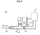
- FIG. 2 is a structural view schematically illustrating an exemplary water spraying unit for the exemplary washing machine in accordance with one or more embodiments of the present disclosure.
- the exemplary washing machine is equipped with an outer tub 20 and an inner tub or drum 30 inside a case 10.
- Water is supplied inside the outer tub 20 using a water supplying unit.
- the rotatable inner tub or drum 30 is disposed inside the outer tub 20.
- the inner tub 30 includes a plurality of holes so that water in the outer tub 20 flows in and out of the inner tub or drum 30.
- a drive unit 40 is disposed at the lower side of (e.g., below) the outer tub 20, and is connected to the inner tub 30 via a shaft 45 extending through the outer tub 20.
- the drive unit 40 rotates the inner tub 30 on a rotation axis perpendicular to its bottom wall or surface.
- a water spraying unit 100 is installed inside the case 10.
- the water spraying unit 100 includes an air storage unit 120, a compression unit 130, a water spraying tube 140, and an opening and closing unit (e.g., valve) 150.
- the air storage unit 120 and the compression unit 130 of the water spraying unit 100 may be inside or outside the case 10.
- the air storage unit 120 is outside the outer tub 20. In the air storage unit 120, air is stored.
- An air supplying unit (not shown) may be connected to the air storage unit 120 to supply external air to the air storage unit 120.
- the air storage unit 120 may be at a position higher than a compression tubing member 133 which will be described below.
- the air storage unit 120 is higher than the compression tubing member 133, the water in the compression tubing portion 133 can be prevented from flowing into the air storage unit 120. Accordingly, before the water in the compression tubing member 133 is guided toward the air storage unit 120, a sufficient amount of air can be stored in the air storage unit 120.
- the compression unit 130 enables communication between the air storage unit 120 and the outer tub 20.
- the compression unit 130 compresses air in the air storage unit 120 by guiding, pumping or forcing water from the outer tub 20 into the air storage unit 120.
- an embodiment of the compression unit 130 will be described.
- An exemplary compression unit 130 includes a connecting tube member 131, a valve 132, a compression tubing member 133, and a compression piston 135.
- the connecting tube member 131 is connected to the outer tub 20.
- the connecting tube member 131 is connected to the lower part (e.g., the lowermost wall or surface) of the outer tub 20 so that water in the outer tub 20 can flow into the connecting tube member 131 without a separate power source.
- the valve 132 is in the connecting tube member 131 where the water from the outer tub 20 flows into the connecting tube member 131. While the valve 132 allows the water from the outer tub 20 to enter the compression tubing member 133, the valve 132 may be a check valve that prevents the water in the compression tubing member 133 from returning to the outer tub 20. Also, the valve 132 may be an opening and closing valve that opens and closes the flow path of the connecting tube member 131.
- the compression tubing member 133 is connected to the connecting tube member 131 and the air storage unit 120.
- the compression tubing member 133 may be or comprise a cylinder that forms a flow path between the connecting tube member 131 and the air storage unit 120. Further, the compression tubing member 133 has sufficient strength to withstand pressure of the water generated when the water is forced, compressed or pumped by the compression piston 135.
- the compression tubing member 133 may have a circular or polygonal cross-sectional shape.
- the compression piston 135 reciprocates in the compression tubing member 133.
- the compression piston 135 may be disposed at a side of the compression tubing member 133 opposite from the air storage unit 120 when viewing the connecting tube member 131.
- the water in the compression tubing member 133 is forced, compressed or pumped by the compression piston 135, the water flows into the air storage unit 120. Air in the air storage unit 120 is compressed until the equilibrium of pressures from the air and the water are increased to a predetermined or approximate value.
- the water spraying tube 140 is connected to the compression unit 130. One side of the water spraying tube 140 is connected to the compression tubing member 133 of the compression unit 130, and another side of the water spraying tube 140 is disposed toward the inside of the inner tub 30.
- the water spraying tube 140 provides a flow path for the water to be sprayed into the inner tub 30 from the compression tubing member 133.
- the opening and closing unit 150 is configured to open and close the flow path of the water spraying tube 140.
- the opening and closing unit 150 may be at a connection between (e.g., the connecting member of) the compressing tubing member 133 and the water spraying tube 140.
- air compressed in the air storage unit 120 forces the water W in the compression unit 130 to be sprayed into the inner tub 30.
- the compressed air of the air storage unit 120 expands (and, for example, the check valve 137 is closed)
- the water in the compression tubing member 133 is pumped through the water spraying tube 140, thereby improving washing efficiency due to increasing the spraying pressure of the water.
- the compression tubing member 133 may further include a check valve 137 between the connecting tube member 131 and the opening and closing unit 150.
- the check valve 137 may prevent the water between the air storage unit 120 and the check valve 137 from returning toward the compression piston 135.
- the check valve 137 allows the water in the compression tubing member 133 to flow only toward the water spraying tube 140, the water W between the check valve 137 and the air storage unit 120 may be prevented from flowing back toward the compression piston 135. Accordingly, when the water W is forced toward the air storage unit 120 by the compression piston 135, the air pressure in the air storage unit 120 may be prevented from decreasing.
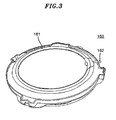
- FIG. 3 is a perspective view illustrating an exemplary tub cover for the exemplary washing machine in accordance with one or more embodiments of the present disclosure
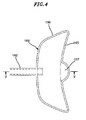
- FIG. 4 is a rear view illustrating an exemplary space forming portion or unit and an exemplary water scattering portion or unit of the exemplary washing machine in accordance with one or more embodiments of the present disclosure
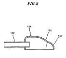
- FIG. 5 is a cross-sectional view taken along line V-V of an exemplary space-forming portion or unit for the exemplary washing machine in accordance with one or more embodiments of the present disclosure.
- an exemplary tub cover 160 includes a main body 161, a spray nozzle 162, a space forming portion or unit 164 and a water scattering portion or unit 167.
- the spray nozzle 162 is connected to the water spraying tube 140 of the water spraying unit 100.
- the spray nozzle 162 may incline downwardly so that the water supplied from the water spraying tube 140 is sprayed into the inner tub 30.
- the spray angle of the spray nozzle 162 may be directed toward the central axis of the inner tub 30.
- the spray nozzle 162 may be integral with the main body 161 of the tub cover 160. With this configuration, the spray direction of the spray nozzle 162 may be prevented from deviating from the normal direction, if an error in assembling occurs. Further, the spray nozzle 162 may be prevented from being separated from the main body 161 of the tub cover 160 while the washing machine is operated. Also, assembling steps and assembling time may be reduced.
- the space forming portion or unit 164 may form and/or provide a water spraying space at the outlet of the spray nozzle 162 (and/or a side thereof).
- the space forming portion or unit 164 may have a rectangular and/or frame (e.g., substantially rectangular or partial arc) that surrounds and/or encompasses space at the outlet of the spray nozzle 162 (and/or a side thereof).
- a rectangular and/or frame e.g., substantially rectangular or partial arc
- the space forming portion or unit 164 may shield or prevent water drops and/or the water from deviating from the spraying space.
- the space forming portion or unit 164 may include a sloped wall 165 which inclines downwardly at a side of the space forming portion or unit 164 opposite from the spray nozzle 162.
- the sloped wall 165 may guide the water sprayed from the spray nozzle 162 to scatter into the inner tub 30.
- the sloped wall 165 may be rounded along the inner periphery of the tub cover 160. As the sloped wall 165 smoothly follows the inner periphery of the tub cover 160, damage to the laundry can be prevented (e.g., possibly caused by hanging or being caught on the inner periphery of the tub cover 160 when the laundry is put into the inner tub 30).
- an expanding wall 166 may expand toward the inside of the tub cover 160 (e.g., from the spray nozzle 162). As the wall(s) 166 allow the spraying space for the water to expand toward the inside of the tub cover 160, the scattering water may be guided along the wall(s) 166, and thus can be smoothly introduced toward or smoothly flow into the inner tub 30.
- the expanding wall(s) 166 spread toward the inside of the tub cover 160, the scattering water flowing toward the (inner) periphery of the tub cover 160 can be guided smoothly toward the inner tub 30.
- the expanding wall(s) 166 of the space forming portion or unit 164 water discharged out of the inner tub 30 and the outer tub 20 can be reduced or minimized.
- the water scattering portion or unit 167 may have a convex shape and be at a side of the space forming portion or unit 164 opposite from the spray nozzle 162 (e.g., at the side of the sloped wall).
- the water scattering portion or unit 167 may to have a shape of a hemisphere or shell cut away in part.
- the exemplary water scattering portion or unit 167 has a hemispherical or shell shape cut away by about half, the water sprayed from the spray nozzle 162 may be scattered into the inner tub 30 within a predetermined range of angles. Further, the water may be scattered relatively evenly to the inner tub 30.
- the water scattering portion or unit 167 may be designed having an appropriate size in accordance with a stream size, a spray amount and/or a spray or flow rate of the water sprayed from the spray nozzle 162.
- the spray nozzle 162 may intensively spray the water onto the water scattering portion or unit 167.
- the sprayed water mostly contacts the water scattering portion or unit 167, and the water can resultantly be sprayed evenly into the inner tub 30. Accordingly, the laundry is quickly wetted by the water W and thus, an interfacial activation and/or action of the detergent and/or debris removal can be actively carried out from the beginning of washing.
- the water scattering portion or unit 167 is at a position where most of the sprayed water flows, most of the water can be scattered into the inner tub 30.
- a portion of the sprayed water W may flow in a sideward direction away from the spray nozzle 162.
- a portion of the scattered water may be guided to the inner tub 30 by the slope(s) of the space forming portion or unit 164. Further, remaining water may be guided into the inner tub 30 by the expanding wall(s) 166 of the space forming portion or unit 164.
- the space forming portion or unit 164 and the water scattering portion or unit 167 can cause the water from the spray nozzle 162 to be scattered evenly into the inner tub 30.
- the laundry can be wetted quickly at the beginning of washing, thereby remarkably improving the washing efficiency and increasing the actual washing time.
- FIG. 6 is a flow chart illustrating an exemplary washing method using the exemplary washing machine in accordance with one or more embodiments of the present disclosure
- FIG. 7 is a structural view illustrating an exemplary process for water to be compressed to the exemplary air storage unit using the exemplary compression unit in accordance with one or more embodiments of the present disclosure
- FIG. 8 is a structural view illustrating spraying water using compressed air from the exemplary air storage unit to the exemplary water spraying tube in accordance with one or more embodiments of the present disclosure
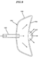
- FIG. 9 is a rear view illustrating water sprayed from the exemplary spray nozzle being scattered by the exemplary water scattering portion or unit in accordance with one or more embodiments of the present disclosure
- FIG. 10 is a cross-sectional view illustrating water sprayed from the spray nozzle being scattered by the exemplary water scattering portion or unit in accordance with one or more embodiments of the present disclosure.
- external water is supplied to the outer tub 20 and/or the inner tub 30 by a water supplying unit (not shown).
- the external water may be supplied to a predetermined level in the outer tub 20 by the water supplying unit according to a user's selection.
- Detergent may also be supplied to the outer tub 20 and/or the inner tub 30, together with or separately from the external water W.
- the inner tub 30 When the external water W is completely supplied to the outer tub 20, the inner tub 30 is rotated from force provided by the drive unit 40 at block S12. By the rotation of the inner tub 30, a current of water occurs and the laundry is washed.
- the washing water W of the outer tub 20 is guided to the compression tubing member 133 via the connecting tube member 131 at block S13.
- the valve 132 of the connecting tube member 131 may allow the water W from the outer tub 20 to flow into the compression tubing member 133.
- the compression piston 135 forces, pumps or otherwise compresses the water W in the compression tubing member 133 toward the air storage unit 120.
- the air in the air storage unit 120 is compressed.
- the air in the air storage unit 120 may be compressed until the equilibrium of forces of the air and the water W has been made (e.g., a predetermined pressure or force is applied to and/or provided by the air in the air storage unit 120 and/or the water W in the air storage unit 120 and the compression tubing member 133).
- the valve 132 of the connecting tube member 131 prevents the water W in the compression tubing member 133 from flowing back towards the piston 135. Accordingly, the valve 132 of the connecting tube member 131 prevents the water W from flowing from the compression tubing member 133 to the outer tub 20, and the compression efficiency of the compression unit 130 can be improved.
- the compression piston 135 As the compression piston 135 reciprocates multiple times, the water W in the compression tubing member 133 and the air in the air storage unit 120 may be compressed to a predetermined pressure. As the number of reciprocations of the compression piston 135 increases, the compression forces of the water W and the air may increase. When the air in the air storage unit 120 is completely compressed, the opening and closing unit 150 may be opened. The number of reciprocations of the compression piston 135 may vary properly in consideration of the capacity of the washing machine and the spraying pressure of the water W.
- the valve 137 in the compression tubing member 133 may prevent the water W from flowing back from the side of the compression tubing member 133 in open communication with the air storage unit 120 to the side of the compression tubing member 133 in open communication with the compression piston 135. Therefore, it is possible to prevent the compression force of the air in the air storage unit 120 from decreasing.
- the opening and closing device 150 When the compression piston 135 has reciprocated a pre-set number of times, the opening and closing device 150 may be opened (see FIG. 8 ). Of course, when the air pressure in the air storage unit 120 has reached to a pre-set pressure, the opening and closing unit 150 may also be opened.
- the control unit may determine, at block S16 ( FIG. 6 ), whether the washing time of the washing machine is over. When the washing time is over, at module S17, operation of the drive unit 40 may be stopped in order to stop the rotation of the inner tub 30.
- the water flows or sprays into the space forming portion or unit 164 and onto the water scattering portion or unit 167 via the spray nozzle 162 (see FIGS. 9 and 10 ).
- the spray nozzle 162 can scatter evenly to the inner tub 30, the laundry is wetted quickly, and thus the washing efficiency can be remarkably improved, and the actual washing time can be increased.
- discharge of the water to the outside of the outer tub 20 can be minimized, thereby minimizing damage to the washing machine caused by moisture or water.
- a rinsing cycle and an optional dehydrating (e.g., drying) cycle may be carried out continuously or sequentially.
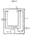
- FIG. 11 is a schematic view illustrating an exemplary washing machine in accordance with one or more further embodiments of the present disclosure.
- the exemplary washing machine includes an outer tub 112 and a tub cover 152.
- the outer tub 112 is installed, and water fills the outer tub 112 from a water supplying unit (not shown).
- the rotatable inner tub 122 is installed in the outer tub 112.
- the inner tub 122 includes a plurality of holes in the cylindrical sidewall for the water to pass through.
- a drive unit 134 is installed below the outer tub 112 and is coupled to the inner tub 122 by a shaft 135 through the outer tub 112.
- the drive unit 134 includes a driving motor and the shaft 135.
- the water spraying unit 140 is connected.
- the water spraying unit 140 includes a water spraying tube 145 which connects the lower side or lowermost surface of the outer tub 112 and the tub cover 152 to each other, and a water pump 141 which is connected to the water spraying tube 145.
- the water spraying unit 140 pumps the washing water from the outer tub 112 and sprays the washing water into the inner tub 122.
- the tub cover 152 is coupled to the upper side of the outer tub 112.
- the tub cover 152 covers the periphery of the upper side of the outer tub 112.
- the tub cover 152 may have an O-, ring or donut shape.
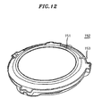
- FIG. 12 is a perspective view of the exemplary tub cover of FIG. 11
- FIG. 13 is an enlarged view of the exemplary spray nozzle of FIG. 12
- FIG. 14 is an enlarged view of the rear or underside of the exemplary tub cover of FIG. 12 .
- the tub cover 152 includes a main body 151, a spray nozzle 153, a branch 153 and a scattering angle limiting portion or unit 157.
- the spray nozzle 153 is formed and is connected to the water spraying tube 145 of the water spraying unit 140.
- the spray nozzle 153 may spray the water supplied from the water spraying tube 145 into the inner tub 122.
- the spray nozzle 153 may have an outlet that slopes downwardly.
- the spray nozzle 153 may be integral with the main body 151 of the tub cover 152. Thus, the direction of the spray nozzle 153 may be prevented from changing, or for the spray nozzle 153 from separating from the main body 151. Further, when the spray nozzle 153 is integral with the main body 151, assembling steps and assembling time of the tub cover 152 can be reduced.
- the branch 156 ( FIG. 14 ) is at a position on the underside of the tub cover 152 opposite to the outlet or end of the spray nozzle 153 (e.g., in the flow path of the water from the spray nozzle 153).
- the branch 156 may have an expanding shape, and extend in opposing directions across the spray nozzle 153. Accordingly, the water sprayed from the spray nozzle 153 can branch away from the spray nozzle 153 (e.g., is opposing directions).
- the branch 156 may have a generally rounded shape, or an angularly bent shape.
- the branch 156 may have a gently rounded arc shape or gently bent (e.g., " ⁇ ") shape.
- an exemplary branch 156 with a " ⁇ " shape will be described by way of example.
- the branch 156 includes an opposing portion or section 154 and an expanding portion or section 155.
- the opposing portion or section 154 may be positioned so as to be opposed to the water outlet or end of the spray nozzle 153 (e.g., in the direct flow or spray of water from the spray nozzle 153). In this case, the opposing portion or section 154 may be spaced apart from the outlet or end of the spray nozzle 153 by a predetermined distance. As the opposing portion or section 154 is opposed to the water outlet or end of the spray nozzle 153, the water sprayed or flowing from the spray nozzle 153 contacts the opposing portion or section 154.
- the expanding portion or section 155 may spread in opposing directions away from the spray nozzle 153 and extend from the opposing portion or section 154.
- the expanding portion or section 155 may slope toward the tub cover 152.
- the water sprayed or flowing from the spray nozzle 153 may scatter into the inner tub 122 using the sloped plane or surface of the expanding portion or section 155.
- the exemplary scattering angle limiting portion or unit 157 is formed and/or positioned so as to oppose the expanding portions or sections 155 of the branch 156.
- the scattering angle limiting portion or unit may consist of a single piece extending on opposed sides of the spray nozzle 153, or comprise a plurality of pieces (e.g., two), each on one side of the spray nozzle 153.
- the scattering angle limiting portion(s) or unit(s) 157 are spaced apart from the expanding portion(s) or section(s) 155 of the branch 156 in order to form a branch flow path 159 together with the branch 156.
- the scattering angle limiting portion(s) or unit(s) 157 may cause the water contacting the branch 156 to be guided with two forked paths or a split path, and can prevent the water from splashing out of or leaving the path(s) defined in part by the scattering angle limiting portion(s) or unit(s) 157.
- the scattering angle limiting portion(s) or unit(s) 157 may be parallel to or along the expanding portion(s) or section(s) 155. Between the scattering angle limiting portion or unit 157 and the expanding portion or section 155, the branch flow path 159 may be formed. Accordingly, the water may be guided smoothly along the branch flow path 159 between the scattering angle limiting portion or unit 157 and the expanding portion or section 155.
- a separation distance between the scattering angle limiting portion or unit 157 and the branch 156 may be suitably designed in consideration of the amount, flow rate and/or pressure of the water from the spray nozzle 153.
- the scattering angle limiting portion or unit 157 may be higher (e.g., have a greater height) than the height of the branch 156. As the scattering angle limiting portion or unit 157 is higher than the height of the branch 156, the water sprayed from the spray nozzle 153 may be prevented from scattering out of the scattering limiting portion or unit 157.
- the height of the scattering angle limiting portion or unit 157 may be determined in consideration of the pressure, flow rate and/or amount of the water from the spray nozzle 153.
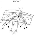
- FIG. 15 is an enlarged view illustrating the spraying form of the water at or on the tub cover of FIG. 14
- FIG. 16 is an enlarged view illustrating the spraying form of the water at or on the branch and the scattering angle limiting portion or unit of FIG. 15 .
- the spray nozzle 153 sprays the water onto the opposing portion or section 154 of the branch 156.
- the water may be guided along the branch flow paths 159 while contacting the expanding portions or sections 155 and the inner side of the scattering angle limiting portions or units 157.
- the expanding portions or sections 155 may be sloped toward the lower and/or inner side of the tub cover 152, and thus the water along the branch flow paths 159 may scatter inside the inner tub 122 along the sloped plane or surface of the expanding portions or sections 155.
- the scattering angle limiting portions or units 157 are parallel or substantially parallel to the (longitudinal) direction of the expanding portions or sections 155, the water along the branch flow path 159 is mostly prevented from flowing over the scattering angle limiting portions or units 157. Accordingly, the water from the spray nozzle can be prevented from scattering outside the inner tub 122 and the outer tub 112.
- the branch 156 and the scattering angle limiting portion(s) or unit(s) 157 may cause the water from the spray nozzle 153 to flow along two forked or split paths, and also may cause the water to scatter onto the laundry within an angle range of the branch flow path(s) 159.
- the water may also be scattered or sprayed within an angle range of the branch 156 or the scattering angle limiting portion(s) or unit(s) 157 in the inner tub 122. Further, the branch 156 and the scattering angle limiting portion or unit 157 make the water to be scattered within a predetermined angle range, and thus the water from the water spraying tube 145 can be scattered or sprayed onto the laundry.
- the water can be sprayed evenly onto the laundry, and thus the laundry can be wetted quickly.
- an interfacial activation action and/or debris removal from the laundry can be initiated from the beginning of the washing cycle. Accordingly, the washing efficiency can be improved.
- the water can be sprayed continuously (or intermittently, but repeatedly) to the inner tub 122, thereby saving a consumption of the water.
- the scattered water can be prevented from being sprayed outside the outer tub 112, thereby preventing electrical/electronic components of the washing machine from being damaged.
Landscapes
- Engineering & Computer Science (AREA)
- Textile Engineering (AREA)
- Detail Structures Of Washing Machines And Dryers (AREA)
- Accessory Of Washing/Drying Machine, Commercial Washing/Drying Machine, Other Washing/Drying Machine (AREA)
Applications Claiming Priority (2)
| Application Number | Priority Date | Filing Date | Title |
|---|---|---|---|
| KR1020130078302A KR101462860B1 (ko) | 2013-07-04 | 2013-07-04 | 세탁기 |
| KR1020130078300A KR101462859B1 (ko) | 2013-07-04 | 2013-07-04 | 세탁기 및 그 세척방법 |
Publications (3)
| Publication Number | Publication Date |
|---|---|
| EP2829651A2 true EP2829651A2 (fr) | 2015-01-28 |
| EP2829651A3 EP2829651A3 (fr) | 2015-05-06 |
| EP2829651B1 EP2829651B1 (fr) | 2017-02-01 |
Family
ID=51167548
Family Applications (1)
| Application Number | Title | Priority Date | Filing Date |
|---|---|---|---|
| EP14002283.1A Not-in-force EP2829651B1 (fr) | 2013-07-04 | 2014-07-03 | Machine à laver et son procédé de lavage |
Country Status (3)
| Country | Link |
|---|---|
| US (1) | US10000885B2 (fr) |
| EP (1) | EP2829651B1 (fr) |
| CN (1) | CN104278472B (fr) |
Families Citing this family (12)
| Publication number | Priority date | Publication date | Assignee | Title |
|---|---|---|---|---|
| KR102376044B1 (ko) * | 2015-09-14 | 2022-03-18 | 엘지전자 주식회사 | 의류처리장치의 제어방법 |
| CN107641932B (zh) * | 2017-10-30 | 2018-08-24 | 郑子健 | 一种空压洗衣机和洗涤方法 |
| CN110878456A (zh) * | 2018-09-05 | 2020-03-13 | 青岛海尔洗衣机有限公司 | 喷嘴、波轮洗衣机及其喷淋系统和外桶盖 |
| CN110878464A (zh) * | 2018-09-05 | 2020-03-13 | 青岛海尔洗衣机有限公司 | 波轮洗衣机及其喷淋系统和外桶盖 |
| CN110878465A (zh) * | 2018-09-05 | 2020-03-13 | 青岛海尔洗衣机有限公司 | 波轮洗衣机及其喷淋系统和外桶盖 |
| JP2022500115A (ja) * | 2018-09-05 | 2022-01-04 | チンタオ ハイアール ウォッシング マシン カンパニー, リミテッドQingdao Haier Washing Machine Co., Ltd. | パルセータ洗濯機及びそのスプレーシステム並びに外ドラムカバー |
| CN110878463A (zh) * | 2018-09-05 | 2020-03-13 | 青岛海尔洗衣机有限公司 | 波轮洗衣机及其喷淋系统和外桶盖 |
| CN109610128B (zh) * | 2018-12-21 | 2021-08-03 | 刘兴海 | 超声波洗衣设备 |
| CN110670294B (zh) * | 2019-11-12 | 2020-11-27 | 珠海格力电器股份有限公司 | 一种洗衣机及洗衣方法 |
| CN112899964B (zh) * | 2019-11-19 | 2024-06-18 | 青岛海尔洗衣机有限公司 | 一种洗涤设备 |
| KR20220021708A (ko) * | 2020-08-14 | 2022-02-22 | 엘지전자 주식회사 | 의류처리장치 |
| CN115247337A (zh) * | 2021-04-26 | 2022-10-28 | 青岛海尔洗衣机有限公司 | 喷嘴结构及具有其的洗涤设备 |
Family Cites Families (23)
| Publication number | Priority date | Publication date | Assignee | Title |
|---|---|---|---|---|
| US3248741A (en) * | 1963-12-31 | 1966-05-03 | Grant E Stout | Portable infant shower-tub |
| DE19935987A1 (de) | 1999-07-30 | 2001-02-01 | Bsh Bosch Siemens Hausgeraete | Wäschebehandlungsmaschine |
| KR100484807B1 (ko) * | 2002-07-30 | 2005-04-22 | 엘지전자 주식회사 | 세탁기의 샤워 커넥터 |
| AU2003259588B2 (en) | 2003-01-20 | 2006-03-02 | Lg Electronics Inc. | Washing machine having floating laundry detecting means and method for controlling the same |
| KR100739548B1 (ko) | 2003-01-20 | 2007-07-16 | 엘지전자 주식회사 | 세탁물 부유 검출 장치를 구비한 세탁기 및 그 제어 방법 |
| KR100688160B1 (ko) * | 2003-08-07 | 2007-03-02 | 엘지전자 주식회사 | 프론트 로딩 타입 드럼 세탁기 |
| KR100540145B1 (ko) * | 2003-08-13 | 2006-01-10 | 엘지전자 주식회사 | 드럼 세탁기의 급수 방법 |
| JP4356424B2 (ja) * | 2003-10-31 | 2009-11-04 | パナソニック株式会社 | 洗濯機 |
| CN2723288Y (zh) | 2004-08-17 | 2005-09-07 | 刘军政 | 随车气压自动冲洗器 |
| DE502006003299D1 (de) | 2006-06-14 | 2009-05-14 | V Zug Ag | Waschmaschine mit Einspritzdüse |
| JP2008104541A (ja) | 2006-10-24 | 2008-05-08 | Toshiba Corp | 洗濯機 |
| AU2010201327B2 (en) * | 2009-04-03 | 2011-11-03 | Lg Electronics Inc. | Washing machine |
| JP5489094B2 (ja) | 2009-05-19 | 2014-05-14 | 株式会社東芝 | 脱水兼用洗濯機 |
| PL2264240T3 (pl) | 2009-06-18 | 2011-09-30 | Miele & Cie | Ładowana od przodu maszyna pralnicza z generatorem pary |
| US9045853B2 (en) * | 2009-10-13 | 2015-06-02 | Lg Electronics Inc. | Laundry treating apparatus |
| KR101688137B1 (ko) | 2010-02-26 | 2016-12-20 | 엘지전자 주식회사 | 액체 분사 장치를 갖는 세탁기 |
| US8914930B2 (en) * | 2010-04-13 | 2014-12-23 | Whirlpool Corporation | Laundry treating appliance with load amount detection |
| CN201722522U (zh) | 2010-05-17 | 2011-01-26 | 南京乐金熊猫电器有限公司 | 洗涤装置 |
| EP2455533B1 (fr) | 2010-11-22 | 2014-06-18 | Electrolux Home Products Corporation N.V. | Procédé de fonctionnement d'une machine à laver et machine à laver |
| DE102010052850B3 (de) | 2010-11-29 | 2012-06-06 | Serva Transport Systems Gmbh | Vorrichtung und Verfahren zum automatischen Quereinlagern eines Kraftfahrzeuges in einer Lagereinrichtung |
| MX353284B (es) * | 2011-08-30 | 2018-01-05 | Mccormick & Co Inc | Rociador de partículas. |
| WO2013066118A1 (fr) * | 2011-11-02 | 2013-05-10 | 주식회사 대우일렉트로닉스 | Appareil d'alimentation en eau pour machine à laver |
| CN102631160B (zh) * | 2012-04-20 | 2014-12-24 | 南京工程学院 | 一种自动循环淋水婴儿澡盆 |
-
2014
- 2014-06-26 US US14/316,101 patent/US10000885B2/en active Active
- 2014-07-02 CN CN201410312021.7A patent/CN104278472B/zh not_active Expired - Fee Related
- 2014-07-03 EP EP14002283.1A patent/EP2829651B1/fr not_active Not-in-force
Non-Patent Citations (1)
| Title |
|---|
| None |
Also Published As
| Publication number | Publication date |
|---|---|
| CN104278472B (zh) | 2017-04-19 |
| US20150007396A1 (en) | 2015-01-08 |
| US10000885B2 (en) | 2018-06-19 |
| EP2829651B1 (fr) | 2017-02-01 |
| EP2829651A3 (fr) | 2015-05-06 |
| CN104278472A (zh) | 2015-01-14 |
Similar Documents
| Publication | Publication Date | Title |
|---|---|---|
| EP2829651B1 (fr) | Machine à laver et son procédé de lavage | |
| EP2476791B1 (fr) | Étui pour détergent et machine à laver dotée de celui-ci | |
| EP2108731B1 (fr) | Machine à laver | |
| RU2664244C1 (ru) | Устройство для обработки белья | |
| US20120006077A1 (en) | Detergent feeding apparatus and washing machine having the same | |
| KR101597527B1 (ko) | 세탁물 처리기기의 제어방법 | |
| US9867519B2 (en) | Dishwasher | |
| US5617747A (en) | Washing machine with water pressurizing and spraying inner tub water passages | |
| US9932702B2 (en) | Washing machine | |
| US5950459A (en) | Electric washing machine including washing tank and agitator which rotate in opposite directions | |
| US9943204B2 (en) | Hand-held laundry treating apparatus | |
| CN108158543B (zh) | 一种新型洗鞋机 | |
| KR102317739B1 (ko) | 펌핑 기능을 가지는 세탁기 | |
| CN106536807B (zh) | 滚筒式洗衣机 | |
| KR20130081114A (ko) | 세제공급장치 및 이를 가지는 세탁기 | |
| KR101462859B1 (ko) | 세탁기 및 그 세척방법 | |
| CN113026287B (zh) | 一种洗衣机及其控制方法 | |
| KR101461391B1 (ko) | 공기발생장치를 갖는 세탁기 | |
| KR19990079727A (ko) | 세탁기의 펄세이터 | |
| KR20110134348A (ko) | 핸드 세탁기 | |
| CN121719044A (zh) | 一种衣物处理设备及其控制方法 | |
| KR0149804B1 (ko) | 분사압을 조절하는 압력조절밸브가 취부된 낙하수류 세탁기 | |
| KR101036818B1 (ko) | 회전하는 압축기를 갖는 세탁기 | |
| US6584634B2 (en) | Hydropneumatic washing device | |
| KR20110134347A (ko) | 상,하부의 물 공급이 가능한 세탁기 |
Legal Events
| Date | Code | Title | Description |
|---|---|---|---|
| 17P | Request for examination filed |
Effective date: 20140703 |
|
| AK | Designated contracting states |
Kind code of ref document: A2 Designated state(s): AL AT BE BG CH CY CZ DE DK EE ES FI FR GB GR HR HU IE IS IT LI LT LU LV MC MK MT NL NO PL PT RO RS SE SI SK SM TR |
|
| AX | Request for extension of the european patent |
Extension state: BA ME |
|
| PUAI | Public reference made under article 153(3) epc to a published international application that has entered the european phase |
Free format text: ORIGINAL CODE: 0009012 |
|
| PUAL | Search report despatched |
Free format text: ORIGINAL CODE: 0009013 |
|
| AK | Designated contracting states |
Kind code of ref document: A3 Designated state(s): AL AT BE BG CH CY CZ DE DK EE ES FI FR GB GR HR HU IE IS IT LI LT LU LV MC MK MT NL NO PL PT RO RS SE SI SK SM TR |
|
| AX | Request for extension of the european patent |
Extension state: BA ME |
|
| RIC1 | Information provided on ipc code assigned before grant |
Ipc: D06F 39/08 20060101AFI20150327BHEP |
|
| 17Q | First examination report despatched |
Effective date: 20151204 |
|
| GRAP | Despatch of communication of intention to grant a patent |
Free format text: ORIGINAL CODE: EPIDOSNIGR1 |
|
| RIC1 | Information provided on ipc code assigned before grant |
Ipc: D06F 35/00 20060101ALN20160823BHEP Ipc: D06F 37/26 20060101ALN20160823BHEP Ipc: D06F 23/04 20060101ALN20160823BHEP Ipc: D06F 39/08 20060101AFI20160823BHEP |
|
| INTG | Intention to grant announced |
Effective date: 20160912 |
|
| STAA | Information on the status of an ep patent application or granted ep patent |
Free format text: STATUS: GRANT OF PATENT IS INTENDED |
|
| GRAS | Grant fee paid |
Free format text: ORIGINAL CODE: EPIDOSNIGR3 |
|
| GRAA | (expected) grant |
Free format text: ORIGINAL CODE: 0009210 |
|
| STAA | Information on the status of an ep patent application or granted ep patent |
Free format text: STATUS: THE PATENT HAS BEEN GRANTED |
|
| AK | Designated contracting states |
Kind code of ref document: B1 Designated state(s): AL AT BE BG CH CY CZ DE DK EE ES FI FR GB GR HR HU IE IS IT LI LT LU LV MC MK MT NL NO PL PT RO RS SE SI SK SM TR |
|
| REG | Reference to a national code |
Ref country code: GB Ref legal event code: FG4D |
|
| REG | Reference to a national code |
Ref country code: CH Ref legal event code: EP Ref country code: AT Ref legal event code: REF Ref document number: 865703 Country of ref document: AT Kind code of ref document: T Effective date: 20170215 |
|
| REG | Reference to a national code |
Ref country code: IE Ref legal event code: FG4D |
|
| REG | Reference to a national code |
Ref country code: DE Ref legal event code: R096 Ref document number: 602014006426 Country of ref document: DE |
|
| REG | Reference to a national code |
Ref country code: FR Ref legal event code: PLFP Year of fee payment: 4 |
|
| REG | Reference to a national code |
Ref country code: NL Ref legal event code: MP Effective date: 20170201 |
|
| REG | Reference to a national code |
Ref country code: LT Ref legal event code: MG4D |
|
| REG | Reference to a national code |
Ref country code: AT Ref legal event code: MK05 Ref document number: 865703 Country of ref document: AT Kind code of ref document: T Effective date: 20170201 |
|
| PG25 | Lapsed in a contracting state [announced via postgrant information from national office to epo] |
Ref country code: FI Free format text: LAPSE BECAUSE OF FAILURE TO SUBMIT A TRANSLATION OF THE DESCRIPTION OR TO PAY THE FEE WITHIN THE PRESCRIBED TIME-LIMIT Effective date: 20170201 Ref country code: NO Free format text: LAPSE BECAUSE OF FAILURE TO SUBMIT A TRANSLATION OF THE DESCRIPTION OR TO PAY THE FEE WITHIN THE PRESCRIBED TIME-LIMIT Effective date: 20170501 Ref country code: IS Free format text: LAPSE BECAUSE OF FAILURE TO SUBMIT A TRANSLATION OF THE DESCRIPTION OR TO PAY THE FEE WITHIN THE PRESCRIBED TIME-LIMIT Effective date: 20170601 Ref country code: GR Free format text: LAPSE BECAUSE OF FAILURE TO SUBMIT A TRANSLATION OF THE DESCRIPTION OR TO PAY THE FEE WITHIN THE PRESCRIBED TIME-LIMIT Effective date: 20170502 Ref country code: HR Free format text: LAPSE BECAUSE OF FAILURE TO SUBMIT A TRANSLATION OF THE DESCRIPTION OR TO PAY THE FEE WITHIN THE PRESCRIBED TIME-LIMIT Effective date: 20170201 Ref country code: LT Free format text: LAPSE BECAUSE OF FAILURE TO SUBMIT A TRANSLATION OF THE DESCRIPTION OR TO PAY THE FEE WITHIN THE PRESCRIBED TIME-LIMIT Effective date: 20170201 |
|
| PG25 | Lapsed in a contracting state [announced via postgrant information from national office to epo] |
Ref country code: ES Free format text: LAPSE BECAUSE OF FAILURE TO SUBMIT A TRANSLATION OF THE DESCRIPTION OR TO PAY THE FEE WITHIN THE PRESCRIBED TIME-LIMIT Effective date: 20170201 Ref country code: PL Free format text: LAPSE BECAUSE OF FAILURE TO SUBMIT A TRANSLATION OF THE DESCRIPTION OR TO PAY THE FEE WITHIN THE PRESCRIBED TIME-LIMIT Effective date: 20170201 Ref country code: SE Free format text: LAPSE BECAUSE OF FAILURE TO SUBMIT A TRANSLATION OF THE DESCRIPTION OR TO PAY THE FEE WITHIN THE PRESCRIBED TIME-LIMIT Effective date: 20170201 Ref country code: AT Free format text: LAPSE BECAUSE OF FAILURE TO SUBMIT A TRANSLATION OF THE DESCRIPTION OR TO PAY THE FEE WITHIN THE PRESCRIBED TIME-LIMIT Effective date: 20170201 Ref country code: NL Free format text: LAPSE BECAUSE OF FAILURE TO SUBMIT A TRANSLATION OF THE DESCRIPTION OR TO PAY THE FEE WITHIN THE PRESCRIBED TIME-LIMIT Effective date: 20170201 Ref country code: PT Free format text: LAPSE BECAUSE OF FAILURE TO SUBMIT A TRANSLATION OF THE DESCRIPTION OR TO PAY THE FEE WITHIN THE PRESCRIBED TIME-LIMIT Effective date: 20170601 Ref country code: RS Free format text: LAPSE BECAUSE OF FAILURE TO SUBMIT A TRANSLATION OF THE DESCRIPTION OR TO PAY THE FEE WITHIN THE PRESCRIBED TIME-LIMIT Effective date: 20170201 Ref country code: LV Free format text: LAPSE BECAUSE OF FAILURE TO SUBMIT A TRANSLATION OF THE DESCRIPTION OR TO PAY THE FEE WITHIN THE PRESCRIBED TIME-LIMIT Effective date: 20170201 Ref country code: BG Free format text: LAPSE BECAUSE OF FAILURE TO SUBMIT A TRANSLATION OF THE DESCRIPTION OR TO PAY THE FEE WITHIN THE PRESCRIBED TIME-LIMIT Effective date: 20170501 |
|
| PG25 | Lapsed in a contracting state [announced via postgrant information from national office to epo] |
Ref country code: RO Free format text: LAPSE BECAUSE OF FAILURE TO SUBMIT A TRANSLATION OF THE DESCRIPTION OR TO PAY THE FEE WITHIN THE PRESCRIBED TIME-LIMIT Effective date: 20170201 Ref country code: SK Free format text: LAPSE BECAUSE OF FAILURE TO SUBMIT A TRANSLATION OF THE DESCRIPTION OR TO PAY THE FEE WITHIN THE PRESCRIBED TIME-LIMIT Effective date: 20170201 Ref country code: IT Free format text: LAPSE BECAUSE OF FAILURE TO SUBMIT A TRANSLATION OF THE DESCRIPTION OR TO PAY THE FEE WITHIN THE PRESCRIBED TIME-LIMIT Effective date: 20170201 Ref country code: CZ Free format text: LAPSE BECAUSE OF FAILURE TO SUBMIT A TRANSLATION OF THE DESCRIPTION OR TO PAY THE FEE WITHIN THE PRESCRIBED TIME-LIMIT Effective date: 20170201 Ref country code: EE Free format text: LAPSE BECAUSE OF FAILURE TO SUBMIT A TRANSLATION OF THE DESCRIPTION OR TO PAY THE FEE WITHIN THE PRESCRIBED TIME-LIMIT Effective date: 20170201 |
|
| PGFP | Annual fee paid to national office [announced via postgrant information from national office to epo] |
Ref country code: DE Payment date: 20170315 Year of fee payment: 4 |
|
| REG | Reference to a national code |
Ref country code: DE Ref legal event code: R097 Ref document number: 602014006426 Country of ref document: DE |
|
| PG25 | Lapsed in a contracting state [announced via postgrant information from national office to epo] |
Ref country code: DK Free format text: LAPSE BECAUSE OF FAILURE TO SUBMIT A TRANSLATION OF THE DESCRIPTION OR TO PAY THE FEE WITHIN THE PRESCRIBED TIME-LIMIT Effective date: 20170201 Ref country code: SM Free format text: LAPSE BECAUSE OF FAILURE TO SUBMIT A TRANSLATION OF THE DESCRIPTION OR TO PAY THE FEE WITHIN THE PRESCRIBED TIME-LIMIT Effective date: 20170201 |
|
| PLBE | No opposition filed within time limit |
Free format text: ORIGINAL CODE: 0009261 |
|
| STAA | Information on the status of an ep patent application or granted ep patent |
Free format text: STATUS: NO OPPOSITION FILED WITHIN TIME LIMIT |
|
| 26N | No opposition filed |
Effective date: 20171103 |
|
| PG25 | Lapsed in a contracting state [announced via postgrant information from national office to epo] |
Ref country code: SI Free format text: LAPSE BECAUSE OF FAILURE TO SUBMIT A TRANSLATION OF THE DESCRIPTION OR TO PAY THE FEE WITHIN THE PRESCRIBED TIME-LIMIT Effective date: 20170201 |
|
| REG | Reference to a national code |
Ref country code: CH Ref legal event code: PL |
|
| REG | Reference to a national code |
Ref country code: IE Ref legal event code: MM4A |
|
| PG25 | Lapsed in a contracting state [announced via postgrant information from national office to epo] |
Ref country code: IE Free format text: LAPSE BECAUSE OF NON-PAYMENT OF DUE FEES Effective date: 20170703 Ref country code: LI Free format text: LAPSE BECAUSE OF NON-PAYMENT OF DUE FEES Effective date: 20170731 Ref country code: CH Free format text: LAPSE BECAUSE OF NON-PAYMENT OF DUE FEES Effective date: 20170731 |
|
| REG | Reference to a national code |
Ref country code: BE Ref legal event code: MM Effective date: 20170731 |
|
| PG25 | Lapsed in a contracting state [announced via postgrant information from national office to epo] |
Ref country code: LU Free format text: LAPSE BECAUSE OF NON-PAYMENT OF DUE FEES Effective date: 20170703 |
|
| REG | Reference to a national code |
Ref country code: FR Ref legal event code: PLFP Year of fee payment: 5 |
|
| PG25 | Lapsed in a contracting state [announced via postgrant information from national office to epo] |
Ref country code: BE Free format text: LAPSE BECAUSE OF NON-PAYMENT OF DUE FEES Effective date: 20170731 |
|
| PG25 | Lapsed in a contracting state [announced via postgrant information from national office to epo] |
Ref country code: MT Free format text: LAPSE BECAUSE OF NON-PAYMENT OF DUE FEES Effective date: 20170703 |
|
| PGFP | Annual fee paid to national office [announced via postgrant information from national office to epo] |
Ref country code: FR Payment date: 20180726 Year of fee payment: 5 |
|
| PGFP | Annual fee paid to national office [announced via postgrant information from national office to epo] |
Ref country code: GB Payment date: 20180725 Year of fee payment: 5 |
|
| REG | Reference to a national code |
Ref country code: DE Ref legal event code: R119 Ref document number: 602014006426 Country of ref document: DE |
|
| PG25 | Lapsed in a contracting state [announced via postgrant information from national office to epo] |
Ref country code: DE Free format text: LAPSE BECAUSE OF NON-PAYMENT OF DUE FEES Effective date: 20190201 |
|
| PG25 | Lapsed in a contracting state [announced via postgrant information from national office to epo] |
Ref country code: HU Free format text: LAPSE BECAUSE OF FAILURE TO SUBMIT A TRANSLATION OF THE DESCRIPTION OR TO PAY THE FEE WITHIN THE PRESCRIBED TIME-LIMIT; INVALID AB INITIO Effective date: 20140703 Ref country code: MC Free format text: LAPSE BECAUSE OF FAILURE TO SUBMIT A TRANSLATION OF THE DESCRIPTION OR TO PAY THE FEE WITHIN THE PRESCRIBED TIME-LIMIT Effective date: 20170201 |
|
| PG25 | Lapsed in a contracting state [announced via postgrant information from national office to epo] |
Ref country code: CY Free format text: LAPSE BECAUSE OF FAILURE TO SUBMIT A TRANSLATION OF THE DESCRIPTION OR TO PAY THE FEE WITHIN THE PRESCRIBED TIME-LIMIT Effective date: 20170201 |
|
| PG25 | Lapsed in a contracting state [announced via postgrant information from national office to epo] |
Ref country code: MK Free format text: LAPSE BECAUSE OF FAILURE TO SUBMIT A TRANSLATION OF THE DESCRIPTION OR TO PAY THE FEE WITHIN THE PRESCRIBED TIME-LIMIT Effective date: 20170201 |
|
| GBPC | Gb: european patent ceased through non-payment of renewal fee |
Effective date: 20190703 |
|
| PG25 | Lapsed in a contracting state [announced via postgrant information from national office to epo] |
Ref country code: TR Free format text: LAPSE BECAUSE OF FAILURE TO SUBMIT A TRANSLATION OF THE DESCRIPTION OR TO PAY THE FEE WITHIN THE PRESCRIBED TIME-LIMIT Effective date: 20170201 |
|
| PG25 | Lapsed in a contracting state [announced via postgrant information from national office to epo] |
Ref country code: GB Free format text: LAPSE BECAUSE OF NON-PAYMENT OF DUE FEES Effective date: 20190703 |
|
| PG25 | Lapsed in a contracting state [announced via postgrant information from national office to epo] |
Ref country code: FR Free format text: LAPSE BECAUSE OF NON-PAYMENT OF DUE FEES Effective date: 20190731 |
|
| PG25 | Lapsed in a contracting state [announced via postgrant information from national office to epo] |
Ref country code: AL Free format text: LAPSE BECAUSE OF FAILURE TO SUBMIT A TRANSLATION OF THE DESCRIPTION OR TO PAY THE FEE WITHIN THE PRESCRIBED TIME-LIMIT Effective date: 20170201 |