EP2829459B1 - Lenkanordnung - Google Patents
Lenkanordnung Download PDFInfo
- Publication number
- EP2829459B1 EP2829459B1 EP14177220.2A EP14177220A EP2829459B1 EP 2829459 B1 EP2829459 B1 EP 2829459B1 EP 14177220 A EP14177220 A EP 14177220A EP 2829459 B1 EP2829459 B1 EP 2829459B1
- Authority
- EP
- European Patent Office
- Prior art keywords
- steering
- hydraulic pressure
- valve
- steer
- pressurised fluid
- Prior art date
- Legal status (The legal status is an assumption and is not a legal conclusion. Google has not performed a legal analysis and makes no representation as to the accuracy of the status listed.)
- Active
Links
Images


Classifications
-
- B—PERFORMING OPERATIONS; TRANSPORTING
- B62—LAND VEHICLES FOR TRAVELLING OTHERWISE THAN ON RAILS
- B62D—MOTOR VEHICLES; TRAILERS
- B62D5/00—Power-assisted or power-driven steering
- B62D5/06—Power-assisted or power-driven steering fluid, i.e. using a pressurised fluid for most or all the force required for steering a vehicle
- B62D5/10—Power-assisted or power-driven steering fluid, i.e. using a pressurised fluid for most or all the force required for steering a vehicle characterised by type of power unit
- B62D5/12—Piston and cylinder
-
- A—HUMAN NECESSITIES
- A01—AGRICULTURE; FORESTRY; ANIMAL HUSBANDRY; HUNTING; TRAPPING; FISHING
- A01B—SOIL WORKING IN AGRICULTURE OR FORESTRY; PARTS, DETAILS, OR ACCESSORIES OF AGRICULTURAL MACHINES OR IMPLEMENTS, IN GENERAL
- A01B69/00—Steering of agricultural machines or implements; Guiding agricultural machines or implements on a desired track
- A01B69/007—Steering or guiding of agricultural vehicles, e.g. steering of the tractor to keep the plough in the furrow
-
- B—PERFORMING OPERATIONS; TRANSPORTING
- B62—LAND VEHICLES FOR TRAVELLING OTHERWISE THAN ON RAILS
- B62D—MOTOR VEHICLES; TRAILERS
- B62D5/00—Power-assisted or power-driven steering
- B62D5/008—Changing the transfer ratio between the steering wheel and the steering gear by variable supply of energy, e.g. by using a superposition gear
-
- B—PERFORMING OPERATIONS; TRANSPORTING
- B62—LAND VEHICLES FOR TRAVELLING OTHERWISE THAN ON RAILS
- B62D—MOTOR VEHICLES; TRAILERS
- B62D5/00—Power-assisted or power-driven steering
- B62D5/06—Power-assisted or power-driven steering fluid, i.e. using a pressurised fluid for most or all the force required for steering a vehicle
- B62D5/09—Power-assisted or power-driven steering fluid, i.e. using a pressurised fluid for most or all the force required for steering a vehicle characterised by means for actuating valves
- B62D5/093—Telemotor driven by steering wheel movement
-
- B—PERFORMING OPERATIONS; TRANSPORTING
- B62—LAND VEHICLES FOR TRAVELLING OTHERWISE THAN ON RAILS
- B62D—MOTOR VEHICLES; TRAILERS
- B62D5/00—Power-assisted or power-driven steering
- B62D5/06—Power-assisted or power-driven steering fluid, i.e. using a pressurised fluid for most or all the force required for steering a vehicle
- B62D5/30—Safety devices, e.g. alternate emergency power supply or transmission means to ensure steering upon failure of the primary steering means
Definitions
- the present invention relates to a steering arrangement.
- a steering arrangements are known whereby a vehicle includes a manually operable steering wheel.
- the steering wheel is mechanically connected to the ground engaging steerable wheels in order to steer the vehicle.
- Certain vehicles in particular agricultural vehicles, when carrying out certain agricultural operations, such as ploughing or spraying in a field, will traverse the field in a generally straight line but at a "headland" such as at the edge of the field, the vehicle will be required to turn a tight circle and return in a direction for which it has just come, in order to continue ploughing, spraying or the like. Under such circumstances, the operator is required to turn the steering wheel quickly and this can be tiresome and/or the operator may not be able to turn the steering wheel quickly enough.
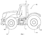
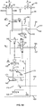
- a vehicle 10 including a steering arrangement according to the present invention.
- the vehicle has a cabin 12 which is mounted on a chassis 13.
- the vehicle 10 has front ground engaging wheels 14A and 14B which are steerable wheels.
- the vehicle also has rear ground engaging wheels 15A and 15B. In this case ground engaging wheels 15A and 15B are not steerable.
- a steering wheel 11 Within the cabin is a steering wheel 11. It can be used to turn the ground engaging steerable wheels about a generally vertical axis to steer the vehicle.
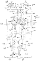
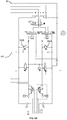
- a steering arrangement 20 With reference to figure 2 , there is shown a steering arrangement 20.
- the main components of the steering arrangement are a pump system 22, a steering system 24, a steering ratio changeover valve 26 and a steering cylinder arrangement 28.
- the steering arrangement includes several back up, or "redundant" components such that in the event of failure of certain of the components, the vehicle 10 can still be steered.
- the steering cylinder arrangement 28 includes a first hydraulic pressure chamber 31, a second hydraulic pressure chamber 32, a third hydraulic pressure chamber 33 and a fourth hydraulic pressure chamber 34.
- the first and second pressure chambers are defined as part of a double acting hydraulic ram 36 having a cylinder 37 and a piston 38.
- the third and fourth hydraulic chambers are defined as part of a double acting hydraulic ram 40 having a cylinder 41 and a piston 42.
- a rod 43 connects piston 38 to piston 42.
- a rod 44 connects piston 38 to a steering arm or the like of the front left wheel.
- a rod 45 connects the piston 42 to a steering arm or the like of the front right wheel.
- the cylinder 37 and 41 are fixed to the chassis/axle or the like of the vehicle.
- the pistons 38 and 42 and rods 43, 44 and 45 define a piston/rod assembly 46 that can move in the direction of arrow A (i.e. to the right when viewing figure 2 ) or in the direction of arrow B (i.e. to the left when viewing figure 2 ) in order to steer the vehicle as will be further described below.
- supplying pressurised hydraulic fluid to one or other or both of the first and third hydraulic pressure chambers causes the piston/rod assembly 46 to move in the direction of arrow A thereby steering the vehicle in one direction.
- supplying pressurised hydraulic fluid to one or other or both of the second and fourth hydraulic pressure chambers causes the piston/rod assembly 46 to move in the direction of arrow B, thereby steering the vehicle in a second direction.
- movement of the piston/rod assembly 46 in the direction of arrow A may steer the vehicle to the right or it may steer the vehicle to the left.
- the steering arrangement 20 includes a hydraulic fluid reservoir 50 which is divided into a first part 50A and a second part 50B by a dividing wall 51.
- the pump system includes a first pump 52A and a second pump 52B. Both the first pump 52A and second pump 52B are driven by a motor M which in this case is the prime mover of the vehicle 10.
- a flow control valve 54A which regulates the flow of pressurised fluid to the steering arrangement 20 with any excess fluid being returned to the hydraulic fluid reservoir 50.
- a flow control valve 54B which similarly regulates the flow of pressurised fluid to the steering arrangement 20, with excess fluid being returned to the hydraulic fluid reservoir 50.
- the steering system 24 includes a first steering unit 56A and a second steering unit 56B.
- the first steering unit 56A consists of a first directional valve 58A in combination with a first metering unit 59A.
- the second steering unit 56B consists of a second directional valve 58B in combination with a second metering unit 59B.
- Each steering unit 56A and 56B may define an orbitrol unit.
- Orbitrol units are well known in the art and they allow metered amounts of pressurised hydraulic fluid to be fed to steering cylinders to steer the vehicle either right or left as appropriate.
- the steering wheel 11 is connected to both steering units 56A and 56B such that turning the steering wheel to the right will cause the first and second steering units 56A and 56B to direct pressurised hydraulic fluid to appropriate hydraulic pressure chambers such that the vehicle steers to the right and turning the steering wheel left causes the first and second steering units 56A and 56B to direct pressurised hydraulic fluid to appropriate hydraulic pressure chambers such that the vehicle steers to the left, as will be further described below.
- the first pump 52A is arranged to draw hydraulic fluid from the first part 50A of the hydraulic fluid reservoir 50 and supply it as pressurised fluid to the first steering unit 56A.
- the first steering unit will be arranged to feed pressurised hydraulic fluid to either the third hydraulic pressure chamber 33 if it is necessary to turn the vehicle in the first direction, or to the fourth hydraulic pressure chamber 34 if it is necessary to turn the vehicle in the second direction or to prevent any fluid being passed either the third or fourth hydraulic pressure chamber if it is necessary to maintain the current steering setting.
- the second pump 52B is arranged to draw hydraulic fluid from the second part 50B of the hydraulic fluid reservoir 50 and to deliver pressurised fluid to the second steering unit 56B.
- the second steering unit 56B is connected to the first steering unit 56A (and to the steering wheel). The first and second steering unit therefore work in conjunction and the second steering unit delivers pressurised fluid either to the first hydraulic pressure chamber, or to the second hydraulic pressure chamber or prevents hydraulic fluid being passed to either the first or the second hydraulic pressure chamber, dependent upon the steering demand.
- first part 50A of the hydraulic fluid reservoir 50, first pump 52A, first steering unit 56A and the double acting hydraulic ram 40 provide a first steering system 61 and the second part 50B of the hydraulic fluid reservoir 50, second pump 52B, second steering unit 56B and the double acting hydraulic ram 36 provide a second steering system 62.
- first steering system 61 together with the second steering system 62 provide a back up system, or a redundant system.
- the steering system also includes a valve 60, the operation of which is described in the applicant's co-pending European patent application 08154567.5 , (see valve structure 32).
- valve 60 is a two position valve which is biased to the position as shown in figure 2 via spring 66 when the vehicle is not in use.
- the first and second pumps will generate a hydraulic pressure in hydraulic lines 80A and 80B. This in turn will cause a hydraulic pressure in the pilot line 90 by virtue of shuttle valve 91.
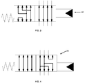
- Orifice 92 maintains the pressure in pilot line 90 such that the valve 60 moves to the position shown in figure 3 .
- first steering unit 56A supplies pressurised hydraulic fluid to the double acting hydraulic ram 40 and the second steering unit 56B supplies pressurised hydraulic fluid to the double acting hydraulic ram 36 as appropriate, depending upon steering demand.
- the steering wheel must be rotated twice as far to obtain the same change in steering direction when compared with when the pumps are working and the valve 60 is in the position shown in figure 3 .
- the steering ratio i.e. the degrees turned by the front ground engaging wheels of the vehicle divided by the degrees turned by the steering wheel is lower with valve 60 positioned as shown in figure 2 then when valve 60 is positioned as shown in figure 3 .
- valve 60 when the valve is positioned as in figure 3 it may take four turns of the steering wheel to move from "lock to lock" (i.e. from full right hand lock to full left hand lock or vice versa) of the ground engaging wheels.
- valve 60 when the valve 60 is in the position as shown in figure 2 it may require 8 turns of the steering wheel to go from lock to lock. This is advantageous since the force required to go from lock to lock with the valve in a positioned shown in figure 2 is therefore less, and since this force is generated by the operator, the operator is more able to steer the vehicle.
- valve 60 Under normal operation, when the vehicle is being used, valve 60 will be in the position as shown in figure 3 and only exceptionally, if ever, when the vehicle is being used will the valve 60 be in the position shown in figure 2 .
- the steering wheel will require, in the above example, four turns to go from lock to lock.
- the steering ratio changeover valve 26 enables the normal steering ratio (in the above example four turns lock to lock) to be selectively altered to a higher ratio (for example two turns lock to lock).
- the steering ratio changeover valve 26 when in the position shown in figure 2 , gives in the example, four turns lock to lock.
- valve 26 can be moved to the position as shown in figure 4 wherein it will only require in this example 2 turns lock to lock.
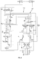
- changeover valve 26 is a pilot operated spool valve which is biased to the position shown in figure 2 by spring 67 but which can be moved to the position showed in figure 4 by application of a pilot pressure in pilot line 92.
- pilot line 92 As shown in figure 2 , with the vehicle in use, the pressure in pilot line 92 will have decayed to zero by virtue of it being connected to drain line 93.
- the operator can operate a switch or the like (not shown) connected to the steering select pilot valve 94 (which is a solenoid operated valve) so as to connect pilot line 90 to pilot line 92.
- pilot line 92 will be pressurised (since the pilot line 90 will be pressurised as described above) thereby causing the steering ratio changeover valve 26 to move to the position shown in figure 4 .
- the output from the steering unit 56A via hydraulic lines 81 or 82
- the output from steering unit 56B via hydraulic lines 83 or 84
- lines 85 and 86 of the double acting hydraulic ram 36 will all be directed to lines 85 and 86 of the double acting hydraulic ram 36.
- none of the output from the first and second steering units 56 will be directed towards the double acting hydraulic ram 40. Instead, lines 87 and 88 associated with the double acting hydraulic ram 40 are coupled together via valve 26 when in the figure 4 position.
- the other double acting hydraulic ram (ram 40) is positioned in a float mode, i.e. the piston 42 is unrestricted in its movement and can freely move in the direction of arrow A or arrow B under the influence of piston 38.
- a sensor in the form of switch 70 detects when the valve 26 is in the figure 2 position and a sensor in the form of switch 71 detects when the valve 26 is in the figure 4 position.
- a sensor in the form of switch 72 detects when the valve 60 is in the position shown in figure 3 . This is for the purpose of a safety check.
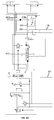
- Steering arrangement 120 is arranged on vehicle 110.
- the steering arrangement 120 can be steered by an operator turning steering wheel 11. Operation in this manner is as described above in relation to steering arrangement 20.
- the steering arrangement 120 can be steered automatically by an automatic steering system, such as a GPS steering system. Under these circumstances, the GPS steering valve 122 can be automatically controlled to steer the vehicle.
- the steering arrangement 120 can be selectively changed between operator steering (manual steering) and automatic steering (GPS steering) by changing the GPS steering select spool valve 124.
- the GPS steering select spool valve 124 With the vehicle 110 in use and in normal steering operation, the GPS steering select spool valve 124 will be in the position as shown in figure 5 .
- the GPS steering safety cut off valve 126 will be in the position as shown in figure 5 . Accordingly, pressurised fluid from pump 52B will flow into line 183 through the GPS steering safety cut off valve 126 and into line 170 and hence on to the GPS steering flow regulator valve 192.
- GPS steering flow regulator valve 192 is a proportional valve and accordingly will connect line 170 to one or other or both of hydraulic lines 171 or 172. Hydraulic fluid flowing through line 172 will flow into line 184 and hence on to the second steering unit 56B. Hydraulic fluid flowing through line 171 will be prevented from flowing through the GPS steering valve 122 and hence will flow through the GPS steering neutral circuit valve 193 and into line 173 and then through line 184 hence onto the second steering unit 56B. Accordingly, the second steering unit 56B is supplied by pressurised fluid from the second pump 52B in a similar manner to the steering arrangement 20 although this pressurised fluid does pass through the GPS steering safety cut off valve 126 and the GPS steering flow regulator valve 192, and some of the fluid passes through the GPS steering neutral circuit valve 193.
- Hydraulic lines 81 and 82 of steering arrangement 120 are connected to hydraulic lines 87 and 88 respectively in a similar manner to steering arrangement 20 (when the valve 60 is in the figure 3 position and the valve 26 is in the figure 5 position).
- Line 84 is connected to line 185 (when valve 60 is in the figure 3 position) which in turn is connected to line 186 (via the GPS steering select spool valve 124 when in the figure 5 position) which in turn is connected to line 86 (when the steering ratio changeover valve 26 is in the figure 5 position).
- line 84 of steering arrangement 120 is connected to line 86 in a similar manner to steering arrangement 20, albeit via the GPS steering select spool valve.
- line 83 is connected to line 187 (when the valve 60 is in the figure 3 position) which in turn is connected to line 188 (via the GPS steering select spool valve 124 when in the figure 5 position) which in turn is connected to line 85 (when the steering ratio changeover valve 26 is in the figure 5 position).
- line 83 of steering arrangement 120 is connected to line 85 in a similar manner to the steering arrangement 20, albeit via the GPS steering select spool valve 124.
- the connections between the pumps 52A and 52B, the steering units 52A and 52B, and the hydraulic rams 36 and 40 as shown in steering arrangement 120 when in the normal mode of operation are functionally equivalent to the connections of the same components in steering arrangement 20 when it is in its normal mode of operation. Accordingly, steering of the steering arrangement 120 when its normal mode is as described above with reference to the steering of steering arrangement 20 when its normal mode of operation.
- GPS steering valve 122 is a proportional valve and is controlled via a GPS steering system which determines automatically where the machine is to be steered. Such GPS steering systems are known and are useful, for example when ploughing a field or carrying out other agricultural operations in a field such as spraying.
- Such GPS steering systems may be more accurate than when the vehicle is being manually steered, and as such will prevent one part of a field being ploughed twice or sprayed twice, and will prevent one part of a field not being ploughed or not being sprayed for example. Furthermore, such automatic steering systems help reduce operator fatigue.
- the GPS steering valve 122 will direct pressurised fluid from hydraulic line 174 into line 188 and on to line 85 and into the first hydraulic pressure chamber 31 to steer the vehicle in the first direction, or the GPS steering valve will direct pressurised fluid into line 186 and then into line 86 and into the second hydraulic pressure chamber 32 to steer the vehicle in the second direction, or, if there is no steering demand, the GPS steering valve 122 will be positioned as shown in figure 5 thereby maintaining the current steering position.
- fluid in the second hydraulic pressure chamber 32 will be returned to the hydraulic fluid reservoir via hydraulic line 86, hydraulic line 186, via GPS steering valve 122, via hydraulic line 173 and 184, through the second steering unit 56B through line 83, through valve 60 (when in the figure 3 position) through line 187 through the GPS steering select spool valve 124 when in the figure 8 position, through line 185, through valve 60 when in the figure 3 position through the second steering unit 56 to tank via drain line 75.
- the GPS steering valve 122 supplies pressurised fluid to the second hydraulic pressure chamber 32, then hydraulic fluid leaving the first hydraulic pressure chamber 31 will be returned to the hydraulic fluid reservoir via a similar route.
- the pump 52B supplies pressurised hydraulic fluid to the GPS steering valve 122.
- the GPS steering valve 122 then directs pressurised hydraulic fluid to one or other or neither of the first and second hydraulic pressure chambers 31 and 32 and also directs return flow from the first or second hydraulic pressure chambers to the hydraulic fluid reservoir 50.
- the piston 38 moves in the direction of arrow A or arrow B, then in turn the piston 42 moves similarly, which in turn causes flow through the metering unit 59A which causes the steering wheel to rotate.
- Rotation of the metering unit 59A and steering wheel 11 causes rotation of the metering unit 59B and this rotation is possible by virtue of the output lines 83 and 84 being connected together at the GPS steering select spool valve 124 when in the figure 8 position.
- the flow from pump 52A will be metered through the first metering unit 59A as it rotates as a result of a steering demand.
- the steering arrangement 120 operates in a similar manner to the steering arrangement 20 in the event that both the first and second pumps are unavailable to supply pressurised hydraulic fluid. In short, under these circumstances the valve 60 moves from the figure 3 position to the figure 2 position resulting in a lower steering ratio.
- the steering arrangement 120 operates in a similar manner to steering arrangement 20 when in a fast steer mode.
- the steering ratio changeover valve 26 moves from the figure 5 position to the figure 4 position thereby resulting in higher steering ratio.
- FIG. 9 shows a steering arrangement 220 which is a variant of the steering arrangement 120.
- Components of steering arrangement 220 which operate in a similar manner to steering arrangement 120 are labelled identically.
- Steering arrangement 220 includes first and second sequence relief valves 250A and 250B. These valves are connected via pilot line 251 to check valve 252.
- sequence relief valves 250A and 250B in combination with the check valve 252 to allow for an increase in the pressure being supplied to steer the vehicle when in the fast steer mode than when compared with the normal mode.
- This increase in pressure may be desirable to compensate for the effective reduction in piston area when operating in this mode.
- the steering select pilot valve 94 shown in figure 9 when in the normal mode, the steering select pilot valve 94 shown in figure 9 is in the position of the steering select pilot valve 94 shown in figure 2 and hence the pilot line 251 is connected to drain line 253 and hence there is no pressure in line 251 and hence the sequence relief valves 250A and 250B will open at, in one example, 100 bar.
- pilot line 90 when the fast steer mode is selected and the steering select pilot valve 94 of figure 9 is moved to the position as shown in figure 9 , then pilot line 90 will pressurise line 251 but only to the cracking pressure of the check valve 252, in one example 60 bar.
- the 60 bar pressure in line 252 supplements the springs within the sequence relief valves 250A and 250B resulting in an increased relief pressure, in this example 160 bars for sequence relief valves 250A and 250B.
- the first and second hydraulic pressure chambers are contained within the double acting hydraulic ram 36 and the third and fourth hydraulic chambers are contained within the double acting hydraulic ram 40.
- the rod 43 serves both the double acting hydraulic ram 36 and the double acting hydraulic ram 40.
- rod 43 may be in two parts with one part serving the double acting hydraulic ram 36 and the second part serving the double acting hydraulic ram 40 with the two parts being distinct parts which are operably coupled together.
- each part may be connected to an associated steering arm with the two steering arms in turn being connected together via a track rod.
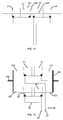
- Figure 10 shows a variant wherein the first hydraulic pressure chamber 31', the second hydraulic pressure chamber 32', the third hydraulic pressure chamber 33' and the fourth hydraulic pressure chamber 34' are all contained within a single cylinder 337.
- a wall (or centre gland) 338 isolates the second hydraulic pressure chamber 32' from the third hydraulic pressure chamber 33' wherein suitable seals engage the rod 343.
- Figure 11 shows an arrangement whereby the first and second hydraulic pressure chambers 31" and 32" are in parallel with the third and fourth hydraulic pressure chambers 33" and 34".
- Rod 450 and rod 451 are coupled together by coupling 453 (shown schematically).
- rod 454 and rod 455 are coupled together by coupling 456 (shown schematically).
- Couplings 453 and 456 are connected via a suitable linkage to the steered ground engaging wheels or the like.
- the invention has been described in respect of a front wheel steered vehicle. However, the invention is equally applicable to vehicles in which the rear wheels steer, or alternatively in respect of vehicles which have centre point steering (also known as articulated steering).
- rods 43, 44 and 45 are described as separate rods. These rods can be attached by an suitable means either to each other, or to an associated piston.
- the attachment means could be a threaded attachment.
- rod 43 and 44 could be a single unitary rod
- rods 44 and 45 could be a single unitary rod
- rods 43, 44 and 45 could all be a single unitary rod.
- motor M is the prime mover of the vehicle, for example a diesel engine.
- any type of prime mover can be used.
- the prime mover may drive the pump via a gear box or the like.
- other types of prime mover other than an internal combustion engine such as a diesel engine might be used.
- One aspect of the present invention uses an automatic steering system, for example a GPS steering system.
- Other types of automatic steering systems could be used, for example, a lane guidance automatic steering system for use on roads could be used.
- the guidance may be via any form of guidance system e.g. laser guidance.
- Such automatic steering systems may be in conformity with UNECE regulation number 79, Uniform Provisions Concerning the Approval of vehicles with Regard to Steering Equipment.
Landscapes
- Engineering & Computer Science (AREA)
- Mechanical Engineering (AREA)
- Chemical & Material Sciences (AREA)
- Combustion & Propulsion (AREA)
- Transportation (AREA)
- Life Sciences & Earth Sciences (AREA)
- Soil Sciences (AREA)
- Environmental Sciences (AREA)
- Steering Control In Accordance With Driving Conditions (AREA)
- Power Steering Mechanism (AREA)
- Non-Deflectable Wheels, Steering Of Trailers, Or Other Steering (AREA)
Claims (12)
- Lenkanordnung (20, 120, 220), enthaltend eine erste hydraulische Druckkammer (31), eine zweite hydraulische Druckkammer (32), eine dritte hydraulische Druckkammer (33) und eine vierte hydraulische Druckkammer (34), wobei die erste und dritte Druckkammer selektiv betreibbar sind, um in eine erste Richtung zu lenken, und die zweite und vierte Druckkammer selektiv betreibbar sind, um in eine zweite Richtung zu lenken,
ein Pumpsystem (22) zum Zuführen von unter Druck stehendem Fluid zu einem Lenksystem (24),
wobei das Lenksystem (24) so betreibbar ist, dass das unter Druck stehende Fluid zu einer oder mehreren der ersten, zweiten, dritten und vierten hydraulischen Druckkammer zugeführt wird,
das Lenksystem (24) einen ersten Modus aufweist, wobei unter Druck stehendes Fluid gleichzeitig der ersten und dritten hydraulischen Druckkammer (31, 33) zugeführt wird, um in die erste Richtung zu lenken, oder wobei unter Druck stehendes Fluid gleichzeitig der zweiten und vierten hydraulischen Druckkammer (32, 34) zugeführt wird, um in die zweite Richtung zu lenken,
dadurch gekennzeichnet, dass das Lenksystem (24) einen zweiten Modus aufweist, wobei unter Druck stehendes Fluid einer der ersten und dritten hydraulischen Druckkammer (31, 33) zugeführt wird, um in die erste Richtung zu lenken, oder wobei unter Druck stehendes Fluid einer der zweiten und vierten hydraulischen Druckkammer (32, 34) zugeführt wird, um in die zweite Richtung zu lenken,
derart, dass das Lenkübersetzung im zweiten Modus größer ist als im ersten Modus. - Lenkanordnung nach Anspruch 1, wobei, mit dem Lenksystem (24) im zweiten Modus, unter Druck stehendes Fluid nur einer der ersten und dritten hydraulischen Druckkammer (31, 33) zugeführt wird, um in die erste Richtung zu lenken, oder unter Druck stehendes Fluid nur einer der zweiten und vierten hydraulischen Druckkammer (32, 34) zugeführt wird, um in die zweite Richtung zu lenken.
- Lenksystem nach Anspruch 1 oder 2, enthaltend
eine erste Lenkeinheit (56A),
eine zweite Lenkeinheit (56B),
wobei, mit dem Lenksystem (24) im ersten Modus,
die erste Lenkeinheit (56A) selektiv unter Druck stehendes Fluid einer der ersten oder dritten Kammer (31, 33) zuführt, gleichzeitig mit der zweiten Lenkeinheit (56B), die unter Druck stehendes Fluid der anderen der ersten oder dritten Kammer (31, 33) zuführt, um in die erste Richtung zu lenken, oder
die erste Lenkeinheit (56A) selektiv unter Druck stehendes Fluid der einen der zweiten oder vierten Kammer (32, 34) zuführt, gleichzeitig mit der zweiten Lenkeinheit (56B), die unter Druck stehendes Fluid der anderen der zweiten oder vierten Kammer (32, 34) zuführt, um in die zweite Richtung zu lenken. - Lenkanordnung nach Anspruch 3, wobei, mit dem Lenksystem (24) im zweiten Modus, die erste Lenkeinheit (56A) selektiv unter Druck stehendes Fluid einer der ersten und dritten hydraulischen Druckkammer (31, 33) zuführt, gleichzeitig mit der zweiten Lenkeinheit (56B), die unter Druck stehendes Fluid der einen der ersten und dritten hydraulischen Druckkammer (31, 33) zuführt, um in die erste Richtung zu lenken, oder
die erste Lenkeinheit (56A) selektiv unter Druck stehendes Fluid einer der zweiten und vierten hydraulischen Druckkammer (32, 34) zuführt, gleichzeitig mit der zweiten Lenkeinheit (56B), die unter Druck stehendes Fluid der einen der zweiten und vierten hydraulischen Druckkammer (32, 34) zuführt, um in die zweite Richtung zu lenken. - Lenkanordnung nach Anspruch 4, enthaltend ein Ventil (26) mit einer ersten Position, die den ersten Modus definiert, und einer zweiten Position, die den zweiten Modus definiert.
- Lenkanordnung nach Anspruch 5, wobei das Ventil (26) ein fremdgesteuertes Ventil oder ein magnetgesteuertes Ventil ist.
- Lenkanordnung nach Anspruch 5 oder 6, enthaltend einen ersten Sensor (70) zum Erkennen, wann sich das Ventil (26) in der ersten Position befindet, und/oder enthaltend einen zweiten Sensor (71), zum Erkennen, wann sich das Ventil (26) in der zweiten Position befindet.
- Lenkanordnung nach einem der Ansprüche 3 bis 7, wobei das Pumpsystem (22) eine erste Pumpe (52A) zum Zuführen von unter Druck stehendem Fluid zur ersten Lenkeinheit (56A) und eine zweite Pumpe (52B) zum Zuführen von unter Druck stehendem Fluid zur zweiten Lenkeinheit (56B) enthält.
- Lenkanordnung nach einem der vorherigen Ansprüche, wobei unter Druck stehendes Fluid einer oder mehreren der ersten, zweiten, dritten und vierten hydraulischen Druckkammer (31, 32, 33, 34) unter geringerem Druck zugeführt wird, wenn sich das Lenksystem (24) im ersten Modus befindet, als der Druck des einer oder mehreren der ersten, zweiten, dritten und vierten hydraulischen Druckkammer (31, 32, 33, 34) zugeführten Fluids, wenn sich das Lenksystem (24) im zweiten Modus befindet.
- Lenkanordnung nach Anspruch 9, wobei ein Überdruckventil angeordnet ist, um Druck des unter Druck stehenden Fluids bei einem ersten Pegel zu entlasten, wenn das Lenksystem (24) im ersten Modus arbeitet, und angeordnet ist, um Druck des unter Druck stehenden Fluids bei einem zweiten Pegel zu entlasten, der höher ist als der erste Pegel, wenn das Lenksystem (24) im zweiten Modus arbeitet.
- Lenkanordnung nach einem der Ansprüche 3 bis 10, wobei das Lenksystem (24) einen dritten Modus aufweist, bei dem nur eine der ersten Lenkeinheit (56A) und zweiten Lenkeinheit (56B) selektiv Fluid der ersten und dritten hydraulischen Druckkammer (31, 34) zuführt, um in eine erste Richtung zu lenken, oder
die eine der ersten Lenkeinheit und zweiten Lenkeinheit selektiv Fluid der zweiten und vierten hydraulischen Druckkammer zuführt, um in die zweite Richtung zu lenken,
derart, dass die Lenkübersetzung im dritten Modus geringer ist als im ersten Modus. - Lenkanordnung nach einem der vorherigen Ansprüche, wobei die Lenkanordnung einen vierten Modus aufweist, wobei unter Druck stehendes Fluid durch ein automatisches Lenksystem einer der ersten und dritten hydraulischen Druckkammer (31, 33) zuführt wird, um in die erste Richtung zu lenken, oder wobei unter Druck stehendes Fluid durch das automatische Lenksystem einer der zweiten und vierten hydraulischen Druckkammer (32, 34) zuführt wird, um in die zweite Richtung zu lenken,
Priority Applications (1)
| Application Number | Priority Date | Filing Date | Title |
|---|---|---|---|
| EP15172582.7A EP2952413B8 (de) | 2013-07-22 | 2014-07-16 | Lenkanordnung |
Applications Claiming Priority (1)
| Application Number | Priority Date | Filing Date | Title |
|---|---|---|---|
| GB1313041.4A GB2516447B (en) | 2013-07-22 | 2013-07-22 | A Steering Arrangement |
Related Child Applications (2)
| Application Number | Title | Priority Date | Filing Date |
|---|---|---|---|
| EP15172582.7A Division EP2952413B8 (de) | 2013-07-22 | 2014-07-16 | Lenkanordnung |
| EP15172582.7A Division-Into EP2952413B8 (de) | 2013-07-22 | 2014-07-16 | Lenkanordnung |
Publications (3)
| Publication Number | Publication Date |
|---|---|
| EP2829459A1 EP2829459A1 (de) | 2015-01-28 |
| EP2829459B1 true EP2829459B1 (de) | 2016-05-04 |
| EP2829459B8 EP2829459B8 (de) | 2021-10-27 |
Family
ID=49119068
Family Applications (2)
| Application Number | Title | Priority Date | Filing Date |
|---|---|---|---|
| EP14177220.2A Active EP2829459B8 (de) | 2013-07-22 | 2014-07-16 | Lenkanordnung |
| EP15172582.7A Active EP2952413B8 (de) | 2013-07-22 | 2014-07-16 | Lenkanordnung |
Family Applications After (1)
| Application Number | Title | Priority Date | Filing Date |
|---|---|---|---|
| EP15172582.7A Active EP2952413B8 (de) | 2013-07-22 | 2014-07-16 | Lenkanordnung |
Country Status (8)
| Country | Link |
|---|---|
| US (1) | US9744986B2 (de) |
| EP (2) | EP2829459B8 (de) |
| JP (1) | JP2015020743A (de) |
| CN (1) | CN104326017B (de) |
| AU (1) | AU2014204535B2 (de) |
| BR (1) | BR102014018012A2 (de) |
| GB (3) | GB2529746A (de) |
| RU (1) | RU2658067C2 (de) |
Families Citing this family (14)
| Publication number | Priority date | Publication date | Assignee | Title |
|---|---|---|---|---|
| DE102016002443A1 (de) * | 2016-02-29 | 2017-08-31 | Bomag Gmbh | Lenkeinrichtung, Baumaschine mit einer Lenkeinrichtung und Verfahren zum Lenken einer lenkbaren Maschine |
| US10259493B2 (en) * | 2016-12-09 | 2019-04-16 | Caterpillar Inc. | Emergency steering pump system for a machine |
| DE102017100186B4 (de) * | 2017-01-06 | 2021-06-10 | Danfoss Power Solutions Aps | Hydraulische Lenkanordnung |
| JP6785671B2 (ja) * | 2017-01-20 | 2020-11-18 | 株式会社クボタ | 作業車 |
| US10668947B2 (en) * | 2017-04-03 | 2020-06-02 | Deere & Company | Electro-hydraulic steering control system |
| CN107697156B (zh) * | 2017-08-04 | 2019-11-08 | 中国煤炭科工集团太原研究院有限公司 | 有防爆电液差速转向控制装置的支架搬运车行走液压驱动系统 |
| US11377144B2 (en) | 2019-06-13 | 2022-07-05 | Cnh Industrial America Llc | Quick response steering system |
| EP4371855A3 (de) * | 2019-07-22 | 2025-02-19 | LS Mtron Ltd. | Hydraulische lenkvorrichtung eines landwirtschaftlichen arbeitsfahrzeugs |
| CN118025306A (zh) * | 2019-07-22 | 2024-05-14 | Ls美创有限公司 | 农业用作业车辆的液压式转向装置 |
| CN110539796B (zh) * | 2019-09-12 | 2021-06-08 | 中联农业机械股份有限公司 | 车辆转向控制方法及系统 |
| US11654960B2 (en) | 2020-04-28 | 2023-05-23 | Deere & Company | Rear steering hydraulic system |
| US11427248B2 (en) | 2020-04-28 | 2022-08-30 | Deere & Company | Rear steering hydraulic system |
| US11246255B2 (en) * | 2020-04-28 | 2022-02-15 | Deere & Company | Rear steering cylinder dampening |
| CN111959604B (zh) * | 2020-07-27 | 2021-10-29 | 农业农村部南京农业机械化研究所 | 一种多模式转向系统 |
Family Cites Families (19)
| Publication number | Priority date | Publication date | Assignee | Title |
|---|---|---|---|---|
| FR2142096B2 (de) * | 1971-07-03 | 1973-07-13 | Zahnradfabrik Friedrichshafen | |
| JPH01168364U (de) * | 1988-05-19 | 1989-11-28 | ||
| US5511457A (en) * | 1994-11-04 | 1996-04-30 | Caterpillar Inc. | Steering control system for an autonomous machine |
| DE19615544C1 (de) * | 1996-04-19 | 1997-10-30 | Daimler Benz Ag | Fahrzeuglenkung |
| JP3687252B2 (ja) * | 1997-02-28 | 2005-08-24 | 日産自動車株式会社 | 自動車の操舵装置 |
| DE19839953C2 (de) * | 1998-09-02 | 2000-06-21 | Daimler Chrysler Ag | Lenksystem für nicht spurgebundene Kraftfahrzeuge |
| DE19839951C2 (de) * | 1998-09-02 | 2000-06-21 | Daimler Chrysler Ag | Lenksystem für nicht spurgebundene Kraftfahrzeuge |
| DE19844331C2 (de) | 1998-09-28 | 2003-09-25 | Sauer Danfoss Holding As Nordb | Hydraulisches Zweikreis-Lenksystem |
| DE19859806B4 (de) * | 1998-12-23 | 2005-03-31 | Daimlerchrysler Ag | Lenksystem für Kraftfahrzeuge |
| DE29915179U1 (de) * | 1999-08-30 | 2000-01-05 | TRW Fahrwerksysteme GmbH & Co KG, 40547 Düsseldorf | Lenksystem für ein Fahrzeug |
| JP2004203087A (ja) * | 2002-12-24 | 2004-07-22 | Toyota Motor Corp | 転舵装置 |
| JP4793008B2 (ja) * | 2006-02-09 | 2011-10-12 | 株式会社デンソー | 車両用操舵装置 |
| JP4902309B2 (ja) * | 2006-10-13 | 2012-03-21 | 日立オートモティブシステムズ株式会社 | ステアリング装置 |
| GB2448914B (en) | 2007-05-03 | 2012-03-07 | Jcb Landpower Ltd | Vehicle |
| US8056672B2 (en) * | 2009-12-09 | 2011-11-15 | Deere & Company | Steering control system combining electro-hydraulic and manually-actuated pilot pressure control valves for safe operation |
| CN201592732U (zh) * | 2010-02-09 | 2010-09-29 | 北京农业信息技术研究中心 | 手动优先的拖拉机自动转向装置 |
| CN202169962U (zh) * | 2011-01-25 | 2012-03-21 | 深圳市达航工业有限公司 | 一种飞机牵引车转向控制装置 |
| CN104144843B (zh) * | 2011-09-30 | 2016-08-24 | 伊顿公司 | 转向控制单元以及电液转向负载敏感控制 |
| US8925672B2 (en) * | 2012-11-20 | 2015-01-06 | Deere & Company | Steering control system for hydrostatically driven front vehicle ground wheels and steerable rear caster wheels |
-
2013
- 2013-07-22 GB GB1510153.8A patent/GB2529746A/en not_active Withdrawn
- 2013-07-22 GB GB1313041.4A patent/GB2516447B/en active Active
- 2013-07-22 GB GB1600219.8A patent/GB2532367B/en active Active
-
2014
- 2014-07-16 US US14/333,312 patent/US9744986B2/en active Active
- 2014-07-16 EP EP14177220.2A patent/EP2829459B8/de active Active
- 2014-07-16 EP EP15172582.7A patent/EP2952413B8/de active Active
- 2014-07-18 JP JP2014147577A patent/JP2015020743A/ja active Pending
- 2014-07-21 RU RU2014129733A patent/RU2658067C2/ru not_active IP Right Cessation
- 2014-07-21 AU AU2014204535A patent/AU2014204535B2/en active Active
- 2014-07-22 BR BR102014018012A patent/BR102014018012A2/pt not_active Application Discontinuation
- 2014-07-22 CN CN201410350644.3A patent/CN104326017B/zh not_active Expired - Fee Related
Also Published As
| Publication number | Publication date |
|---|---|
| JP2015020743A (ja) | 2015-02-02 |
| GB201313041D0 (en) | 2013-09-04 |
| BR102014018012A2 (pt) | 2016-04-12 |
| US9744986B2 (en) | 2017-08-29 |
| EP2952413B8 (de) | 2021-10-27 |
| AU2014204535A1 (en) | 2015-02-05 |
| GB2529746A (en) | 2016-03-02 |
| AU2014204535B2 (en) | 2017-08-24 |
| GB2516447B (en) | 2016-06-15 |
| GB2532367B (en) | 2017-06-28 |
| RU2658067C2 (ru) | 2018-06-19 |
| GB201510153D0 (en) | 2015-07-29 |
| RU2014129733A (ru) | 2016-02-10 |
| EP2829459B8 (de) | 2021-10-27 |
| GB2532367A (en) | 2016-05-18 |
| GB2516447A (en) | 2015-01-28 |
| GB201600219D0 (en) | 2016-02-17 |
| EP2952413A1 (de) | 2015-12-09 |
| US20150021116A1 (en) | 2015-01-22 |
| CN104326017A (zh) | 2015-02-04 |
| EP2829459A1 (de) | 2015-01-28 |
| EP2952413B1 (de) | 2018-09-19 |
| CN104326017B (zh) | 2018-10-02 |
Similar Documents
| Publication | Publication Date | Title |
|---|---|---|
| EP2829459B1 (de) | Lenkanordnung | |
| US11396323B2 (en) | Electro-hydraulic steering control system | |
| US8925672B2 (en) | Steering control system for hydrostatically driven front vehicle ground wheels and steerable rear caster wheels | |
| US9101090B2 (en) | Windrower autoguidance hydraulic steering interface | |
| EP2113445B1 (de) | Belastungsreaktionslenksystem mit Isolationsventil | |
| EP0856453B1 (de) | Elektrohydraulisches Lenksystem für Fahrzeuge | |
| US8412420B2 (en) | Wheel lean control | |
| US11318988B2 (en) | Hydraulic steering control system | |
| EP2576322A1 (de) | Hydromechanische lenkeinheit mit integrierte notlenkungsfunktion | |
| US20160068182A1 (en) | Electrohydraulic steer-by-wire steering system | |
| CA1274780A (en) | Fully metered compensating steering system | |
| JPH0150626B2 (de) | ||
| EP1048549B1 (de) | Hydrostatische Kraftfahrzeugservolenkung für erhöhte Geschwindigkeit | |
| DE10138563A1 (de) | Rad-Straßenfertiger und Verfahren zum Lenken eines Rad-Straßenfertigers | |
| EP3996971B1 (de) | Lenksystem mit umschaltbarem lastreaktionsventil | |
| US20020092697A1 (en) | Steering system for a vehicle | |
| KR102411623B1 (ko) | 유압식 파워 스티어링 장치 | |
| JP7235206B2 (ja) | 作業車両 | |
| US20170144700A1 (en) | Hydraulically assisted steering system |
Legal Events
| Date | Code | Title | Description |
|---|---|---|---|
| 17P | Request for examination filed |
Effective date: 20140716 |
|
| AK | Designated contracting states |
Kind code of ref document: A1 Designated state(s): AL AT BE BG CH CY CZ DE DK EE ES FI FR GB GR HR HU IE IS IT LI LT LU LV MC MK MT NL NO PL PT RO RS SE SI SK SM TR |
|
| AX | Request for extension of the european patent |
Extension state: BA ME |
|
| PUAI | Public reference made under article 153(3) epc to a published international application that has entered the european phase |
Free format text: ORIGINAL CODE: 0009012 |
|
| R17P | Request for examination filed (corrected) |
Effective date: 20150528 |
|
| RBV | Designated contracting states (corrected) |
Designated state(s): AL AT BE BG CH CY CZ DE DK EE ES FI FR GB GR HR HU IE IS IT LI LT LU LV MC MK MT NL NO PL PT RO RS SE SI SK SM TR |
|
| GRAP | Despatch of communication of intention to grant a patent |
Free format text: ORIGINAL CODE: EPIDOSNIGR1 |
|
| RIC1 | Information provided on ipc code assigned before grant |
Ipc: B62D 5/00 20060101ALI20151027BHEP Ipc: A01B 69/00 20060101ALI20151027BHEP Ipc: B62D 5/30 20060101ALI20151027BHEP Ipc: B62D 5/093 20060101AFI20151027BHEP |
|
| INTG | Intention to grant announced |
Effective date: 20151112 |
|
| GRAS | Grant fee paid |
Free format text: ORIGINAL CODE: EPIDOSNIGR3 |
|
| GRAA | (expected) grant |
Free format text: ORIGINAL CODE: 0009210 |
|
| AK | Designated contracting states |
Kind code of ref document: B1 Designated state(s): AL AT BE BG CH CY CZ DE DK EE ES FI FR GB GR HR HU IE IS IT LI LT LU LV MC MK MT NL NO PL PT RO RS SE SI SK SM TR |
|
| REG | Reference to a national code |
Ref country code: GB Ref legal event code: FG4D |
|
| REG | Reference to a national code |
Ref country code: CH Ref legal event code: EP |
|
| REG | Reference to a national code |
Ref country code: AT Ref legal event code: REF Ref document number: 796633 Country of ref document: AT Kind code of ref document: T Effective date: 20160515 |
|
| REG | Reference to a national code |
Ref country code: IE Ref legal event code: FG4D |
|
| REG | Reference to a national code |
Ref country code: DE Ref legal event code: R096 Ref document number: 602014001789 Country of ref document: DE |
|
| REG | Reference to a national code |
Ref country code: FR Ref legal event code: PLFP Year of fee payment: 3 |
|
| REG | Reference to a national code |
Ref country code: NL Ref legal event code: MP Effective date: 20160504 |
|
| REG | Reference to a national code |
Ref country code: LT Ref legal event code: MG4D |
|
| PG25 | Lapsed in a contracting state [announced via postgrant information from national office to epo] |
Ref country code: NL Free format text: LAPSE BECAUSE OF FAILURE TO SUBMIT A TRANSLATION OF THE DESCRIPTION OR TO PAY THE FEE WITHIN THE PRESCRIBED TIME-LIMIT Effective date: 20160504 Ref country code: NO Free format text: LAPSE BECAUSE OF FAILURE TO SUBMIT A TRANSLATION OF THE DESCRIPTION OR TO PAY THE FEE WITHIN THE PRESCRIBED TIME-LIMIT Effective date: 20160804 Ref country code: FI Free format text: LAPSE BECAUSE OF FAILURE TO SUBMIT A TRANSLATION OF THE DESCRIPTION OR TO PAY THE FEE WITHIN THE PRESCRIBED TIME-LIMIT Effective date: 20160504 Ref country code: LT Free format text: LAPSE BECAUSE OF FAILURE TO SUBMIT A TRANSLATION OF THE DESCRIPTION OR TO PAY THE FEE WITHIN THE PRESCRIBED TIME-LIMIT Effective date: 20160504 |
|
| REG | Reference to a national code |
Ref country code: AT Ref legal event code: MK05 Ref document number: 796633 Country of ref document: AT Kind code of ref document: T Effective date: 20160504 |
|
| PG25 | Lapsed in a contracting state [announced via postgrant information from national office to epo] |
Ref country code: SE Free format text: LAPSE BECAUSE OF FAILURE TO SUBMIT A TRANSLATION OF THE DESCRIPTION OR TO PAY THE FEE WITHIN THE PRESCRIBED TIME-LIMIT Effective date: 20160504 Ref country code: ES Free format text: LAPSE BECAUSE OF FAILURE TO SUBMIT A TRANSLATION OF THE DESCRIPTION OR TO PAY THE FEE WITHIN THE PRESCRIBED TIME-LIMIT Effective date: 20160504 Ref country code: GR Free format text: LAPSE BECAUSE OF FAILURE TO SUBMIT A TRANSLATION OF THE DESCRIPTION OR TO PAY THE FEE WITHIN THE PRESCRIBED TIME-LIMIT Effective date: 20160805 Ref country code: HR Free format text: LAPSE BECAUSE OF FAILURE TO SUBMIT A TRANSLATION OF THE DESCRIPTION OR TO PAY THE FEE WITHIN THE PRESCRIBED TIME-LIMIT Effective date: 20160504 Ref country code: RS Free format text: LAPSE BECAUSE OF FAILURE TO SUBMIT A TRANSLATION OF THE DESCRIPTION OR TO PAY THE FEE WITHIN THE PRESCRIBED TIME-LIMIT Effective date: 20160504 Ref country code: PT Free format text: LAPSE BECAUSE OF FAILURE TO SUBMIT A TRANSLATION OF THE DESCRIPTION OR TO PAY THE FEE WITHIN THE PRESCRIBED TIME-LIMIT Effective date: 20160905 Ref country code: LV Free format text: LAPSE BECAUSE OF FAILURE TO SUBMIT A TRANSLATION OF THE DESCRIPTION OR TO PAY THE FEE WITHIN THE PRESCRIBED TIME-LIMIT Effective date: 20160504 |
|
| PG25 | Lapsed in a contracting state [announced via postgrant information from national office to epo] |
Ref country code: BE Free format text: LAPSE BECAUSE OF NON-PAYMENT OF DUE FEES Effective date: 20160731 |
|
| PG25 | Lapsed in a contracting state [announced via postgrant information from national office to epo] |
Ref country code: CZ Free format text: LAPSE BECAUSE OF FAILURE TO SUBMIT A TRANSLATION OF THE DESCRIPTION OR TO PAY THE FEE WITHIN THE PRESCRIBED TIME-LIMIT Effective date: 20160504 Ref country code: RO Free format text: LAPSE BECAUSE OF FAILURE TO SUBMIT A TRANSLATION OF THE DESCRIPTION OR TO PAY THE FEE WITHIN THE PRESCRIBED TIME-LIMIT Effective date: 20160504 Ref country code: DK Free format text: LAPSE BECAUSE OF FAILURE TO SUBMIT A TRANSLATION OF THE DESCRIPTION OR TO PAY THE FEE WITHIN THE PRESCRIBED TIME-LIMIT Effective date: 20160504 Ref country code: SK Free format text: LAPSE BECAUSE OF FAILURE TO SUBMIT A TRANSLATION OF THE DESCRIPTION OR TO PAY THE FEE WITHIN THE PRESCRIBED TIME-LIMIT Effective date: 20160504 Ref country code: EE Free format text: LAPSE BECAUSE OF FAILURE TO SUBMIT A TRANSLATION OF THE DESCRIPTION OR TO PAY THE FEE WITHIN THE PRESCRIBED TIME-LIMIT Effective date: 20160504 |
|
| REG | Reference to a national code |
Ref country code: DE Ref legal event code: R097 Ref document number: 602014001789 Country of ref document: DE |
|
| PG25 | Lapsed in a contracting state [announced via postgrant information from national office to epo] |
Ref country code: PL Free format text: LAPSE BECAUSE OF FAILURE TO SUBMIT A TRANSLATION OF THE DESCRIPTION OR TO PAY THE FEE WITHIN THE PRESCRIBED TIME-LIMIT Effective date: 20160504 Ref country code: SM Free format text: LAPSE BECAUSE OF FAILURE TO SUBMIT A TRANSLATION OF THE DESCRIPTION OR TO PAY THE FEE WITHIN THE PRESCRIBED TIME-LIMIT Effective date: 20160504 Ref country code: AT Free format text: LAPSE BECAUSE OF FAILURE TO SUBMIT A TRANSLATION OF THE DESCRIPTION OR TO PAY THE FEE WITHIN THE PRESCRIBED TIME-LIMIT Effective date: 20160504 Ref country code: BE Free format text: LAPSE BECAUSE OF FAILURE TO SUBMIT A TRANSLATION OF THE DESCRIPTION OR TO PAY THE FEE WITHIN THE PRESCRIBED TIME-LIMIT Effective date: 20160504 |
|
| PLBE | No opposition filed within time limit |
Free format text: ORIGINAL CODE: 0009261 |
|
| STAA | Information on the status of an ep patent application or granted ep patent |
Free format text: STATUS: NO OPPOSITION FILED WITHIN TIME LIMIT |
|
| PG25 | Lapsed in a contracting state [announced via postgrant information from national office to epo] |
Ref country code: MC Free format text: LAPSE BECAUSE OF FAILURE TO SUBMIT A TRANSLATION OF THE DESCRIPTION OR TO PAY THE FEE WITHIN THE PRESCRIBED TIME-LIMIT Effective date: 20160504 |
|
| 26N | No opposition filed |
Effective date: 20170207 |
|
| REG | Reference to a national code |
Ref country code: IE Ref legal event code: MM4A |
|
| PG25 | Lapsed in a contracting state [announced via postgrant information from national office to epo] |
Ref country code: SI Free format text: LAPSE BECAUSE OF FAILURE TO SUBMIT A TRANSLATION OF THE DESCRIPTION OR TO PAY THE FEE WITHIN THE PRESCRIBED TIME-LIMIT Effective date: 20160504 |
|
| REG | Reference to a national code |
Ref country code: FR Ref legal event code: PLFP Year of fee payment: 4 |
|
| PG25 | Lapsed in a contracting state [announced via postgrant information from national office to epo] |
Ref country code: IE Free format text: LAPSE BECAUSE OF NON-PAYMENT OF DUE FEES Effective date: 20160716 |
|
| PG25 | Lapsed in a contracting state [announced via postgrant information from national office to epo] |
Ref country code: LU Free format text: LAPSE BECAUSE OF NON-PAYMENT OF DUE FEES Effective date: 20160716 |
|
| REG | Reference to a national code |
Ref country code: CH Ref legal event code: PL |
|
| PG25 | Lapsed in a contracting state [announced via postgrant information from national office to epo] |
Ref country code: LI Free format text: LAPSE BECAUSE OF NON-PAYMENT OF DUE FEES Effective date: 20170731 Ref country code: CH Free format text: LAPSE BECAUSE OF NON-PAYMENT OF DUE FEES Effective date: 20170731 |
|
| PG25 | Lapsed in a contracting state [announced via postgrant information from national office to epo] |
Ref country code: HU Free format text: LAPSE BECAUSE OF FAILURE TO SUBMIT A TRANSLATION OF THE DESCRIPTION OR TO PAY THE FEE WITHIN THE PRESCRIBED TIME-LIMIT; INVALID AB INITIO Effective date: 20140716 |
|
| PG25 | Lapsed in a contracting state [announced via postgrant information from national office to epo] |
Ref country code: MT Free format text: LAPSE BECAUSE OF NON-PAYMENT OF DUE FEES Effective date: 20160731 Ref country code: MK Free format text: LAPSE BECAUSE OF FAILURE TO SUBMIT A TRANSLATION OF THE DESCRIPTION OR TO PAY THE FEE WITHIN THE PRESCRIBED TIME-LIMIT Effective date: 20160504 Ref country code: IS Free format text: LAPSE BECAUSE OF FAILURE TO SUBMIT A TRANSLATION OF THE DESCRIPTION OR TO PAY THE FEE WITHIN THE PRESCRIBED TIME-LIMIT Effective date: 20160504 Ref country code: CY Free format text: LAPSE BECAUSE OF FAILURE TO SUBMIT A TRANSLATION OF THE DESCRIPTION OR TO PAY THE FEE WITHIN THE PRESCRIBED TIME-LIMIT Effective date: 20160504 |
|
| REG | Reference to a national code |
Ref country code: FR Ref legal event code: PLFP Year of fee payment: 5 |
|
| PG25 | Lapsed in a contracting state [announced via postgrant information from national office to epo] |
Ref country code: BG Free format text: LAPSE BECAUSE OF FAILURE TO SUBMIT A TRANSLATION OF THE DESCRIPTION OR TO PAY THE FEE WITHIN THE PRESCRIBED TIME-LIMIT Effective date: 20160504 |
|
| PG25 | Lapsed in a contracting state [announced via postgrant information from national office to epo] |
Ref country code: AL Free format text: LAPSE BECAUSE OF FAILURE TO SUBMIT A TRANSLATION OF THE DESCRIPTION OR TO PAY THE FEE WITHIN THE PRESCRIBED TIME-LIMIT Effective date: 20160504 Ref country code: TR Free format text: LAPSE BECAUSE OF FAILURE TO SUBMIT A TRANSLATION OF THE DESCRIPTION OR TO PAY THE FEE WITHIN THE PRESCRIBED TIME-LIMIT Effective date: 20160504 |
|
| PGFP | Annual fee paid to national office [announced via postgrant information from national office to epo] |
Ref country code: IT Payment date: 20190729 Year of fee payment: 6 |
|
| GRAT | Correction requested after decision to grant or after decision to maintain patent in amended form |
Free format text: ORIGINAL CODE: EPIDOSNCDEC |
|
| PLAA | Information modified related to event that no opposition was filed |
Free format text: ORIGINAL CODE: 0009299DELT |
|
| PLBE | No opposition filed within time limit |
Free format text: ORIGINAL CODE: 0009261 |
|
| R26N | No opposition filed (corrected) |
Effective date: 20170207 |
|
| RAP4 | Party data changed (patent owner data changed or rights of a patent transferred) |
Owner name: J.C. BAMFORD EXCAVATORS LIMITED |
|
| 26N | No opposition filed |
Effective date: 20170207 |
|
| PG25 | Lapsed in a contracting state [announced via postgrant information from national office to epo] |
Ref country code: IT Free format text: LAPSE BECAUSE OF NON-PAYMENT OF DUE FEES Effective date: 20200716 |
|
| P01 | Opt-out of the competence of the unified patent court (upc) registered |
Effective date: 20230525 |
|
| PGFP | Annual fee paid to national office [announced via postgrant information from national office to epo] |
Ref country code: DE Payment date: 20250722 Year of fee payment: 12 |
|
| PGFP | Annual fee paid to national office [announced via postgrant information from national office to epo] |
Ref country code: GB Payment date: 20250716 Year of fee payment: 12 |
|
| PGFP | Annual fee paid to national office [announced via postgrant information from national office to epo] |
Ref country code: FR Payment date: 20250725 Year of fee payment: 12 |