EP2829365B1 - Verfahren und Vorrichtung zum Bremsen einer Roboterachsanordnung - Google Patents
Verfahren und Vorrichtung zum Bremsen einer Roboterachsanordnung Download PDFInfo
- Publication number
- EP2829365B1 EP2829365B1 EP14002391.2A EP14002391A EP2829365B1 EP 2829365 B1 EP2829365 B1 EP 2829365B1 EP 14002391 A EP14002391 A EP 14002391A EP 2829365 B1 EP2829365 B1 EP 2829365B1
- Authority
- EP
- European Patent Office
- Prior art keywords
- brake
- output member
- braking
- braking force
- robot
- Prior art date
- Legal status (The legal status is an assumption and is not a legal conclusion. Google has not performed a legal analysis and makes no representation as to the accuracy of the status listed.)
- Active
Links
- 238000000034 method Methods 0.000 title claims description 24
- 230000033001 locomotion Effects 0.000 claims description 16
- 238000005516 engineering process Methods 0.000 claims description 11
- 238000001514 detection method Methods 0.000 claims description 9
- 230000001133 acceleration Effects 0.000 claims description 5
- 238000004590 computer program Methods 0.000 claims description 3
- 230000008569 process Effects 0.000 claims description 3
- 230000001419 dependent effect Effects 0.000 claims 1
- 230000005540 biological transmission Effects 0.000 description 9
- 230000000694 effects Effects 0.000 description 7
- 238000011161 development Methods 0.000 description 5
- 230000018109 developmental process Effects 0.000 description 5
- 230000006870 function Effects 0.000 description 5
- 238000012986 modification Methods 0.000 description 3
- 230000004048 modification Effects 0.000 description 3
- 238000012544 monitoring process Methods 0.000 description 3
- 230000036461 convulsion Effects 0.000 description 2
- 238000004519 manufacturing process Methods 0.000 description 2
- 230000007246 mechanism Effects 0.000 description 2
- 238000012545 processing Methods 0.000 description 2
- 238000004891 communication Methods 0.000 description 1
- 238000013270 controlled release Methods 0.000 description 1
- 230000001934 delay Effects 0.000 description 1
- 238000013461 design Methods 0.000 description 1
- 238000002474 experimental method Methods 0.000 description 1
- 210000003746 feather Anatomy 0.000 description 1
- 239000012530 fluid Substances 0.000 description 1
- 238000010438 heat treatment Methods 0.000 description 1
- 230000010354 integration Effects 0.000 description 1
- 230000003287 optical effect Effects 0.000 description 1
Images

Classifications
-
- B—PERFORMING OPERATIONS; TRANSPORTING
- B25—HAND TOOLS; PORTABLE POWER-DRIVEN TOOLS; MANIPULATORS
- B25J—MANIPULATORS; CHAMBERS PROVIDED WITH MANIPULATION DEVICES
- B25J19/00—Accessories fitted to manipulators, e.g. for monitoring, for viewing; Safety devices combined with or specially adapted for use in connection with manipulators
- B25J19/0004—Braking devices
-
- B—PERFORMING OPERATIONS; TRANSPORTING
- B25—HAND TOOLS; PORTABLE POWER-DRIVEN TOOLS; MANIPULATORS
- B25J—MANIPULATORS; CHAMBERS PROVIDED WITH MANIPULATION DEVICES
- B25J11/00—Manipulators not otherwise provided for
-
- B—PERFORMING OPERATIONS; TRANSPORTING
- B25—HAND TOOLS; PORTABLE POWER-DRIVEN TOOLS; MANIPULATORS
- B25J—MANIPULATORS; CHAMBERS PROVIDED WITH MANIPULATION DEVICES
- B25J9/00—Programme-controlled manipulators
- B25J9/16—Programme controls
-
- B—PERFORMING OPERATIONS; TRANSPORTING
- B25—HAND TOOLS; PORTABLE POWER-DRIVEN TOOLS; MANIPULATORS
- B25J—MANIPULATORS; CHAMBERS PROVIDED WITH MANIPULATION DEVICES
- B25J9/00—Programme-controlled manipulators
- B25J9/16—Programme controls
- B25J9/1674—Programme controls characterised by safety, monitoring, diagnostic
-
- G—PHYSICS
- G05—CONTROLLING; REGULATING
- G05B—CONTROL OR REGULATING SYSTEMS IN GENERAL; FUNCTIONAL ELEMENTS OF SUCH SYSTEMS; MONITORING OR TESTING ARRANGEMENTS FOR SUCH SYSTEMS OR ELEMENTS
- G05B2219/00—Program-control systems
- G05B2219/30—Nc systems
- G05B2219/41—Servomotor, servo controller till figures
- G05B2219/41279—Brake
-
- G—PHYSICS
- G05—CONTROLLING; REGULATING
- G05B—CONTROL OR REGULATING SYSTEMS IN GENERAL; FUNCTIONAL ELEMENTS OF SUCH SYSTEMS; MONITORING OR TESTING ARRANGEMENTS FOR SUCH SYSTEMS OR ELEMENTS
- G05B2219/00—Program-control systems
- G05B2219/30—Nc systems
- G05B2219/41—Servomotor, servo controller till figures
- G05B2219/41285—Dynamic brake of ac, dc motor
-
- G—PHYSICS
- G05—CONTROLLING; REGULATING
- G05B—CONTROL OR REGULATING SYSTEMS IN GENERAL; FUNCTIONAL ELEMENTS OF SUCH SYSTEMS; MONITORING OR TESTING ARRANGEMENTS FOR SUCH SYSTEMS OR ELEMENTS
- G05B2219/00—Program-control systems
- G05B2219/30—Nc systems
- G05B2219/42—Servomotor, servo controller kind till VSS
- G05B2219/42284—Stop and brake motor
Definitions
- the present invention relates to a method for braking a robot axis arrangement as well as a robot axis arrangement and a computer program product for carrying out such a method.
- Robots have a robot axis arrangement with one or more robot (movement) axes. These are actuated by drives in order to move the robot and, for example, to follow a predetermined path with a reference point that is fixed to the robot, such as the TCP ("Tool Center Point"). In order to brake an axis, the drive applies an opposing drive torque during normal operation.
- TCP Tool Center Point
- a robot axis can have a brake in order to fix the stationary axis when the drive is de-energized.
- the drive is disconnected from an energy supply according to in-house practice and at the same time this additional brake is quickly closed in order to stop the axis quickly and reliably.
- the structure of the robot and / or the brake which is usually only designed to fix the stationary axis, can be subjected to high dynamic loads. Additionally or alternatively, brakes can vary in their effect, in particular due to manufacturing and / or assembly tolerances, and thus lead to high loads.
- a robot which has at least two parts that can move relative to one another, drives for realizing at least two separate movements between the parts, at least two separate brakes to counteract one of the at least two separate movements, and a control device that is connected to the brakes and has is set up to activate at least one of the brakes while the other remains inactive.
- the WO 01/62449 A1 discloses a permanent magnet braking system consisting of a first body with an active surface and a second body with an active surface, fluid being located between the first and second active surfaces since a magnetic field is activated when the brake is activated.
- a system comprising a braking mechanism capable of changing the amount of braking torque by changing a control value, a state detection part that detects whether the braking mechanism is in a braking or holding state, a storage part that stores the control value stores, and a motion control operation part indicating the control value to be stored.
- the object of the present invention is to improve braking of a robot axis arrangement, in particular down to a standstill.
- Claim 9 protects a corresponding robot axis arrangement, claim 14 a computer program product, in particular a machine-readable data carrier, for carrying out such a method.
- the subclaims relate to advantageous developments.
- a robot axis arrangement comprises a single or several, in particular all, robot axes of one or more robots, in particular at least one six-axis or multi-axis industrial or lightweight robot.
- a robot axis has an output member which, in one embodiment, is permanently or detachably connected to a robot member in a rotationally and / or axially fixed manner.
- the one robot member can be rotatably and / or displaceably mounted on a further robot member and / or moved against it by means of the output member.
- the robot axis has a drive for impressing a driving force on the output member.
- the drive can in particular have one or more electric motors, in particular mechanically coupled in parallel or in series. Additionally or alternatively, the drive can be a gear, in particular a spur gear, preferably a planetary gear, and / or sliding wedge gear or
- the output member can in particular have, in particular be, the rotor or stator of an electric motor of the drive or an output shaft, in particular an outer ring, of a gearbox of the drive.
- the robot axis has an additional brake for applying a braking force to the output member.
- the brake can in particular have, in particular be, a holding brake for fixing the output member.
- the brake is a deenergized closed brake which is or is opened or released in normal operation by active actuation, for example energy supply to at least one electromagnet.
- the brake can have, in particular, an (electro) mechanical, hydraulic or pneumatic brake.
- the brake has a spring means for bracing two brake members against one another and an actuator, in particular electromagnetic and / or motor-driven, for spacing the brake members apart or for actively releasing the brake.
- the brake is arranged between the drive motor and drive, in one Another embodiment on a side of a drive motor facing away from the transmission or on a side of a drive transmission facing away from the motor.
- the robot axis arrangement has a control means for controlling the driving force and / or the braking force of a single or several, in particular all, axes of the robot axis arrangement.
- a means within the meaning of the present invention can be designed in terms of hardware and / or software, in particular a processing, in particular microprocessor unit (CPU) and / or a, preferably digital, processing unit (CPU) and / or a data or signal connected to a memory and / or bus system or have several programs or program modules.
- the CPU can be designed to process commands which are implemented as a program stored in a memory system, to acquire input signals from a data bus and / or to output output signals to a data bus.
- a storage system can have one or more, in particular different, storage media, in particular optical, magnetic, solid-state and / or other non-volatile media.
- the program can be designed in such a way that it embodies or is able to execute the methods described here, so that the CPU can execute the steps of such methods and thus in particular control the axle drive (s) and / or brake (s).
- the control means can in particular be a robot controller of the robot with the axes of the robot axis arrangement.
- the control means for controlling the drive and / or the braking force can only be designed for a single axis and can be arranged in a robot member in which the drive and / or the brake is arranged. This avoids long communication paths and the control for avoiding or reducing high loads can take place directly and on an axis-by-axis basis.
- controlling is understood to mean, in particular, commanding or actuating exclusively on the basis of a predetermined one-dimensional or multi-dimensional variable (“feedforward control”).
- a control in the sense of the present invention can in particular also be a regulation, ie a command or actuation on the basis of a comparison a predetermined one-dimensional or multi-dimensional variable with a determined actual size (“feedback control").
- feedback control both are generally referred to as control for a more compact presentation.
- a braking force is applied to one or more output members by the brake (s) acting on them.
- the braking force can in particular be impressed on the moving output member in order to brake it, in particular to shut it down.
- the braking force is applied on the basis of an operating exception.
- An operating exception within the meaning of the present invention can in particular be a state deviating from normal operation, in particular traveling a specified working path, in particular an unscheduled shutdown, for example as a result of an emergency stop, safety monitoring or the like.
- an additional brake in particular a holding brake, for braking, in particular stopping, at least one axis of a robot is closed, for example as a result of an emergency stop.
- the structure of the robot and / or the brake (s), in particular a bearing and / or fastening can be subject to high dynamic loads: if the brake is applied, the output member is briefly loaded with the full inertia of the axis, in particular a massive robot limb moving at high speed or other robot limbs connected to it.
- a braking effect can spread over a relatively large area, so that very high loads can occur with individual brakes.
- the respective additional brake when the brake is closed or when one or more axles or output members are braked, the respective additional brake, in particular during the entire braking until the axle comes to a standstill or at least in sections during braking, the driving force of the respective, Acting on the output member drive based on a controlled dynamic size of the output member, which depends on the braking force.
- the drive force is additionally also before and / or after the braking of the axle (s) or output members by the respective additional brake or additionally also when the brake is not or has already been released, in particular due to inertia or errors, on the basis of a controlled dynamic size of the output member, which depends on the braking force.
- the drive is controlled, at least in sections during braking, in the opposite direction to the brake or accelerating the axis in order to reduce a deceleration and thus a load on the structure and / or brake, i.e. to counteract the braking effect. Since the drive and braking force add up in the output member, the total load can be reduced accordingly.
- the drive is controlled, at least in sections during braking, in the same direction as the brake or decelerating the axis, in order also to exert a braking effect and thus to reduce the load on the brake.
- these two versions can be combined or the drive can be controlled in the opposite direction to the brake during at least one section of braking and in the same direction to the brake in at least one section of braking which is different from this or which is spaced apart in time.
- the brake exerts a high braking force, for example as a result of heating, and thus in particular loads the robot
- its braking effect and thus the load can be reduced
- the brake for example still cold
- brake exerts a low braking force and thus in particular lengthened the braking distance
- the drive to the brake or a brake booster can only act in the same direction, in particular to avoid increased wear of the brake due to a drive acting in opposite directions and / or an extension of the braking distance.
- Controlling the drive force can be particularly advantageous if the brake is a binary brake that can only be switched between an open and a closed state without being able to specify its braking force in between.
- the braking force of the respective brake acting on the output member is controlled on the basis of a dynamic variable of the output member, which depends on the braking force, in particular on the basis of the same dynamic variable on the basis of which the driving force is also controlled.
- the braking force can be limited or, at least in phases, reduced in order to reduce stress on the structure and / or the brake.
- an, in particular maximum, deceleration of the robot axis can be reduced in one embodiment. This can reduce the load on the structure and / or the brake, especially when stopping rapidly moving axes. Additionally or alternatively, a braking effect can be divided between the drive and the brake, thus relieving the brake itself.
- the one-dimensional or multidimensional dynamic variable can include, in particular, a force that acts on or in the output member or is exerted by it.
- a force within the meaning of the present invention can in one embodiment also be an anti-parallel force pair, i.e. comprise a torque, which is generally referred to as force in the present case for a more compact representation.
- this force and thus also a load on the structure of the robot and / or the brake can be reduced.
- the dynamic variable can comprise a one-dimensional or multi-dimensional movement variable of the output member, in particular it can be, in particular, a speed ⁇ (t), an acceleration d ⁇ / dt, a jerk d 2 ⁇ / dt 2 and / or a higher time derivative.
- a load when braking by the brake depends on a deceleration, in particular on a speed profile or jerks or changes in acceleration that occur in the process.
- a load can also be estimated by determining a movement quantity or a load can be reduced by controlling on the basis of the movement quantity.
- the drive and / or the braking force is controlled on the basis of a difference between the dynamic variable and a predetermined limit value, in particular in such a way that exceeding the limit value, in particular in terms of amount, is avoided, shortened and / or reduced.
- the one- or multi-dimensional limit value can include, in particular be, a predetermined maximum load, in particular force, in particular a maximum torque, of the output member. Then, in one embodiment, the drive and / or the brake can be controlled in such a way that an actual or actual load does not exceed this maximum load during braking, only briefly exceeds it, or exceeds it as little as possible.
- a maximum torque can be a maximum of 1000 Nm, in particular 600 Nm, preferably a maximum of 100 Nm, in particular in the case of a lightweight robot.
- a maximum torque in one embodiment can amount to a maximum of 50,000 Nm, in particular a maximum of 10,000 Nm.
- the limit value can include, in particular be, a predefined one-dimensional or multi-dimensional maximum movement variable, in particular acceleration, of the output member. Then, in one embodiment, the drive and / or the brake can be controlled in such a way that an actual or actual movement variable does not exceed this maximum value in terms of amount during braking, only briefly exceeds it or exceeds it as little as possible.
- the limit value can be fixed, adjustable or variable.
- the limit value comprises a force that is to act on or in the output member or to be exerted by it, in particular a setpoint braking torque.
- a target value to be achieved is generally referred to as a limit value for a more compact representation.
- the limit value is specified on the basis of a movement variable of the output member, in particular a difference between a setpoint and an actual movement variable of the output member.
- a speed controller can specify a target braking torque in order to achieve a target speed, in particular to reduce the speed to zero, preferably to run down a braking ramp.
- the drive and / or braking force is then controlled on the basis of the difference between the limit value, in particular this target braking torque, and a force acting on or in the output member or exerted by it.
- a drive and / or a braking force can be controlled proportionally to a difference between the dynamic variable and a predetermined limit value and / or a time derivative and / or a time interval of this difference, in particular by a proportional, integral and / or differential control.
- the drive and / or the braking force can be controlled on the basis of a model of the robot axis arrangement. In one embodiment, this allows the dynamics of the robot axis arrangement, in particular its inertia, to be taken into account.
- the dynamic variable is determined using secure technology, in particular redundantly, preferably diversely.
- the drive and / or braking force can be controlled using safe technology or at least control variables for controlling the drive and / or braking force, in particular setpoint and / or control values, can be determined using safe technology. While a control of the drive or braking force in safe technology presupposes safe drives or brakes, safe monitoring can advantageously be implemented with little effort on the basis of control variables determined in safe technology.
- the drive and / or braking force is preferably controlled at a frequency of at least 100 Hz, preferably at least 1 kHz, preferably at least 10 kHz, in order to regulate loads on the structure and / or brake (s) at an early stage.
- the braking force and the driving force can be controlled in parallel branches or via parallel channels, so that if one branch or channel fails, the other branch or channel can continue to brake the robot axis (s). If, for example, the brake fails, the drive alone can brake the robot axis (s), in particular bring it to a standstill. Conversely, the brake alone can brake the robot axis (s), in particular bring it to a standstill, if the drive fails or is faulty.
- the drive and / or the brake can be monitored in an embodiment using safe technology, in particular a force exerted by the drive and / or the brake and / or a movement variable, in particular speed, of the output member.
- This monitoring can include, in particular, forming a difference value between a force exerted by the drive or the brake and / or a movement variable of the output member with an expected value, in particular a predetermined limit value, and a comparison of this difference value with a threshold value. If this threshold value is exceeded, one of the two parallel actuators is switched powerless to stop the axis in one version. This can be done in particular by releasing the brake or by disconnecting the power supply to the drive.
- the robot axis arrangement has a detection means for determining the dynamic variable of one or more output members.
- the detection means can in particular have a force sensor, preferably a torque sensor, which in one embodiment is operatively connected to the output member, in particular is fastened to it.
- the detection means can have, in particular, a joint position and / or speed and / or acceleration sensor, preferably a rotation angle sensor, which in one embodiment is operatively connected to the output member, in particular fastened to it.
- the detection means is arranged on the output side, in particular on a side of a transmission of the drive unit facing away from the motor and / or a side of the brake facing away from the motor and / or transmission, in particular between the output member and a robot member moved by it, for example a robot swing arm or hand .
- Fig. 1 shows an axis A of a robot axis arrangement according to an embodiment of the present invention.
- the axis can, for example, be a base or arm axis of a six-axis or multi-axis industrial or lightweight robot. Further axes of the robot, which is otherwise not shown, can be constructed and braked in the same way or be as described below with reference to the axis A shown.
- the robot axis has an output member in the form of an output shaft 1 of a transmission 4.3, 4.4 of an axle drive, which is rotationally and axially fixedly connected to a robot element 2.1, which is rotatably supported by means of the output shaft via bearings 3 on a further robot element 2.2.
- an electric motor with a stator 4.1 and a rotor 4.2 is provided, which is coupled to the output shaft 1 by gearwheels 4.3, 4.4 of the transmission.
- an additional brake with a spring means 5.1 for tensioning a rotor-fixed brake member in the form of a brake disc 5.2 and a multi-part brake member in the form of brake linings 5.3 and an electromagnetic actuator 5.4 for spacing the brake members 5.2, 5.3 apart or for active, controlled release of the brake on a side facing away from the gearbox (right in Fig. 1 ) of the drive motor 3.1, 3.2 arranged.
- the brake can be installed between the drive motor and gearbox or on a side of a drive gearbox facing away from the motor (left in Fig. 1 ) be arranged.
- the transmission can be designed as a harmonic drive transmission.
- the brake is designed as a holding brake for securing the output shaft 1 as an energy-free closed brake, which is opened or released during normal operation by supplying energy to the electromagnets 5.4.
- a control means for controlling the driving force and / or the braking force of the axis A of the robot is implemented in an axis control 6 which is arranged in the further robot element 2.2 in which the drive and the brake are arranged.
- a detection means in the form of a torque sensor 7 for determining a dynamic variable in the form of a torque T is arranged between the robot member 2. Both the determination of the torque and the control of the drive and the brake by the axis control are designed using safe technology, in particular redundant, preferably diverse.
- FIG. 8 shows a method for braking the robot axle assembly of FIG Fig. 1 according to an embodiment of the present invention, as it is carried out by the control means in the form of the axis control 6.
- a step S10 the axle control 6 controls the actuator 5.4 of the brake on the basis of an operational exception, for example an emergency stop N, in order to apply a braking torque T B, s .
- an emergency stop N for example an emergency stop N
- the additional holding brake for stopping axis A as a result of an emergency stop (S10: "Y") is applied.
- the structure of the robot and / or the brake can be dynamically highly loaded: as soon as the brake closes, the output shaft 1 is briefly loaded with the full inertia of the axis A, in particular of the robot member 2.1 moving at high speed.
- the setpoint drive torque T M, s of the electric motor 4.1, 4.2 is set on the basis of the value in the output shaft 1 acting torque T determined by the torque sensor 7, which in turn depends on the current actual braking force T B, i.
- specified between the torque T and a specified limit value T max : T M. , s ⁇ M. T M. , i ⁇ with the current actual drive torque T M, i and a function ⁇ M stored in the axis control 6, which, when the limit value T max , ie ⁇ ⁇ 0, is exceeded, applies a drive torque that is opposite to the brake and counteracts the deceleration of axis A. This slows down braking and thus reduces the load.
- the electric motor 4.1, 4.2 compensates for part of the braking torque of the closed brake 5.1-5.4 and thus reduces the deceleration of the axis A and thus in particular the load on the output shaft 1. This can be particularly advantageous if the brake is only fully open. and can be closed without being able to specify the braking force in between.
- the functions ⁇ M , ⁇ B can contain a particularly dynamic model of the robot axis arrangement in order to take into account the dynamics of the robot axis arrangement, in particular its inertia.
- the braking and drive torques T B, i , T M, i add up.
- a very simple function ⁇ M can be designed in the same way in order to reduce the total torque T in the output shaft 1.
- FIG. 13 shows part of the control means of the robot axis arrangement of FIG Fig. 1 according to a modification of the embodiment explained above.
- the torque controller 6.2 compares the actual torque T recorded by the torque sensor 7 in the output shaft with this target braking torque T s and sends a corresponding target current value after limiting to a maximum value to a current controller 6.3, which in turn supplies the stator 4.1 of the electric motor.
- control means 6 has a brake control 6.4 which closes the brake 5.1-5.4 if an emergency stop N has been detected.
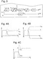
- FIGS 4A-4C show the torque T (dash-dotted lines in Fig. 4 ) as well as the actual torques T M, i (drawn out in Fig. 4 ) and T B, i (dashed lines in Fig. 4 ) of the electric motor or the brake in the robot axis arrangement of Fig. 1 as they are by the control means 6 of the Fig. 3 be realized.
- the speed controller 6.1 then commands a maximum setpoint braking torque T s, max based on the difference between the actual speed and the setpoint speed 0, which the torque controller 6.2 seeks to bring about by appropriate braking control of the electric motor.
- the actual torque T M, i of the electric motor initially rises sharply.
- the brake control 6.4 also closes the brake 5.1-5.4, so that the actual torque T B, i of the brake also increases with a time delay.
- the mechanical summation of the two actual torques T M, i and T B, i results in a brief overshoot of the torque T in the output shaft 1. This is recorded by the torque sensor 7.
- the torque controller 6.2 reduces the braking torque to be applied by the electric motor, the brake essentially takes over the braking of the output shaft and is supported by the drive acting in the same direction.
- the torque controller 6.2 applies a torque in the opposite direction to the torque of the brake by means of the electric motor.
- the torque regulator 6.2 reduces the braking torque to be applied by the electric motor to zero.
Landscapes
- Engineering & Computer Science (AREA)
- Robotics (AREA)
- Mechanical Engineering (AREA)
- Manipulator (AREA)
- Automatic Assembly (AREA)
Applications Claiming Priority (1)
| Application Number | Priority Date | Filing Date | Title |
|---|---|---|---|
| DE102013012448.4A DE102013012448A1 (de) | 2013-07-26 | 2013-07-26 | Verfahren und Vorrichtung zum Bremsen einer Roboterachsanordnung |
Publications (3)
| Publication Number | Publication Date |
|---|---|
| EP2829365A2 EP2829365A2 (de) | 2015-01-28 |
| EP2829365A3 EP2829365A3 (de) | 2015-03-11 |
| EP2829365B1 true EP2829365B1 (de) | 2021-03-03 |
Family
ID=51176880
Family Applications (1)
| Application Number | Title | Priority Date | Filing Date |
|---|---|---|---|
| EP14002391.2A Active EP2829365B1 (de) | 2013-07-26 | 2014-07-11 | Verfahren und Vorrichtung zum Bremsen einer Roboterachsanordnung |
Country Status (5)
| Country | Link |
|---|---|
| US (2) | US9956693B2 (zh) |
| EP (1) | EP2829365B1 (zh) |
| KR (1) | KR20150013057A (zh) |
| CN (1) | CN104369190B (zh) |
| DE (1) | DE102013012448A1 (zh) |
Families Citing this family (18)
| Publication number | Priority date | Publication date | Assignee | Title |
|---|---|---|---|---|
| DE102013012448A1 (de) * | 2013-07-26 | 2015-01-29 | Kuka Laboratories Gmbh | Verfahren und Vorrichtung zum Bremsen einer Roboterachsanordnung |
| FR3019953B1 (fr) * | 2014-04-09 | 2016-05-06 | Staubli Sa Ets | Procede de commande d'un robot multi-axes et robot pour la mise en oeuvre d'un tel procede |
| JP2016082685A (ja) * | 2014-10-15 | 2016-05-16 | 本田技研工業株式会社 | ブラシレスモータ及び電動パワーステアリング装置 |
| DE102014222809B3 (de) * | 2014-11-07 | 2016-01-14 | Kuka Roboter Gmbh | Event-basierte Redundanzwinkelkonfiguartion für Gelenkarmroboter |
| KR20230174291A (ko) | 2015-05-06 | 2023-12-27 | 스니프르 테크놀로지스 리미티드 | 미생물 개체군 변경 및 미생물군 변형 |
| JP2017028810A (ja) * | 2015-07-18 | 2017-02-02 | 多摩川精機株式会社 | モータ安全停止構造、モータ制御システム、モータ制御方法およびヒューマノイドロボット |
| US11045059B2 (en) * | 2016-03-31 | 2021-06-29 | Miraikikai, Inc. | Self-propelled robot |
| GB201609811D0 (en) | 2016-06-05 | 2016-07-20 | Snipr Technologies Ltd | Methods, cells, systems, arrays, RNA and kits |
| IT201700025766A1 (it) * | 2017-03-08 | 2018-09-08 | Epistolio S R L | Robot di verniciatura |
| US10386856B2 (en) | 2017-06-29 | 2019-08-20 | Uber Technologies, Inc. | Autonomous vehicle collision mitigation systems and methods |
| EP3498433A1 (en) * | 2017-12-14 | 2019-06-19 | Universal Robots A/S | Dynamical safety trajectories in a robotic system |
| US10760075B2 (en) | 2018-04-30 | 2020-09-01 | Snipr Biome Aps | Treating and preventing microbial infections |
| US20210387335A1 (en) * | 2018-10-12 | 2021-12-16 | Abb Schweiz Ag | Method And Control System For Determining Dynamic Friction Torque, And Industrial Robot |
| CN110253622B (zh) * | 2019-06-21 | 2021-01-22 | 深圳岱仕科技有限公司 | 旋转关节及旋转关节的防碰撞方法 |
| DE102019120344B4 (de) * | 2019-07-26 | 2023-10-12 | Deutsches Zentrum für Luft- und Raumfahrt e.V. | Aktuatorvorrichtung, Robotergelenkvorrichtung und Roboter |
| EP4115250A1 (de) | 2020-03-03 | 2023-01-11 | Sew-Eurodrive GmbH & Co. KG | Verfahren zum abbremsen eines objekts und maschine |
| CN113084821A (zh) * | 2021-04-30 | 2021-07-09 | 哈尔滨工业大学 | 一种基于动力学的喷涂机器人时间最优轨迹规划方法 |
| CN114260900B (zh) * | 2021-12-30 | 2023-08-29 | 库卡机器人制造(上海)有限公司 | 机器人的减速控制方法和装置、机器人组件和存储介质 |
Family Cites Families (18)
| Publication number | Priority date | Publication date | Assignee | Title |
|---|---|---|---|---|
| DE2442865C3 (de) * | 1974-09-06 | 1979-07-05 | Hagenuk Vormals Neufeldt & Kuhnke Gmbh, 2300 Kiel | Vorrichtung, insbesondere Manipulator, zum raschen Bewegen und genauen Positionieren eines Laststellglieds längs eines vorgegebenen Weges |
| JP3217892B2 (ja) * | 1993-03-11 | 2001-10-15 | 株式会社日立製作所 | ブレーキ装置及びマニピュレータ装置 |
| JP3070498B2 (ja) | 1996-12-03 | 2000-07-31 | 松下電器産業株式会社 | ロボットの制御装置 |
| SE0000606D0 (sv) * | 2000-02-23 | 2000-02-23 | Abb Ab | Anordning vid robot |
| WO2003016745A2 (de) * | 2001-08-16 | 2003-02-27 | Wabco Gmbh & Co.Ohg | Zuspanneinrichtung für eine bremse |
| EP1905552A1 (en) * | 2006-09-29 | 2008-04-02 | Abb Research Ltd. | A robot with at least two separate brake devices and a method of controlling such a robot |
| JP2008307618A (ja) * | 2007-06-12 | 2008-12-25 | Denso Wave Inc | ロボットの制御装置 |
| JP2009095939A (ja) * | 2007-10-17 | 2009-05-07 | Yaskawa Electric Corp | ロボットおよびロボットシステム |
| CN101888920B (zh) * | 2007-12-07 | 2012-10-03 | 株式会社安川电机 | 机器人动作限制方法、机器人系统和机器人动作限制装置 |
| DE102008041866B3 (de) * | 2008-09-08 | 2010-04-29 | Deutsches Zentrum für Luft- und Raumfahrt e.V. | Verfahren zum Überprüfen einer Bremse eines Roboters |
| WO2011036750A1 (ja) * | 2009-09-24 | 2011-03-31 | 株式会社 東芝 | ロボット制御装置 |
| US8751040B2 (en) * | 2010-04-02 | 2014-06-10 | GM Global Technology Operations LLC | Systems and methods for evaluating braking performance |
| DE102011005985B4 (de) | 2011-03-23 | 2019-01-24 | Kuka Roboter Gmbh | Roboter, Steuervorrictung für einen Roboter und Verfahren zum Betreiben eines Roboters |
| JP2013184236A (ja) * | 2012-03-06 | 2013-09-19 | Jtekt Corp | ロボットのキャリブレーション方法及びキャリブレーション装置 |
| DE102013012448A1 (de) * | 2013-07-26 | 2015-01-29 | Kuka Laboratories Gmbh | Verfahren und Vorrichtung zum Bremsen einer Roboterachsanordnung |
| CA2940490C (en) * | 2014-03-04 | 2022-07-12 | Universal Robots A/S | Safety system for industrial robot |
| DE102014222678A1 (de) * | 2014-11-06 | 2016-05-12 | Kuka Roboter Gmbh | Verfahren und System zum Stillsetzen von Achsen eines Industrieroboters |
| JP6770019B2 (ja) * | 2018-05-10 | 2020-10-14 | ファナック株式会社 | 複数のモータが1つの動作軸を駆動する駆動装置、及び駆動装置を備えるロボット |
-
2013
- 2013-07-26 DE DE102013012448.4A patent/DE102013012448A1/de active Pending
-
2014
- 2014-07-11 EP EP14002391.2A patent/EP2829365B1/de active Active
- 2014-07-23 US US14/339,093 patent/US9956693B2/en active Active
- 2014-07-24 KR KR1020140093818A patent/KR20150013057A/ko active Search and Examination
- 2014-07-28 CN CN201410364830.2A patent/CN104369190B/zh active Active
-
2018
- 2018-03-19 US US15/925,099 patent/US10792821B2/en active Active
Non-Patent Citations (1)
| Title |
|---|
| None * |
Also Published As
| Publication number | Publication date |
|---|---|
| DE102013012448A1 (de) | 2015-01-29 |
| CN104369190A (zh) | 2015-02-25 |
| US9956693B2 (en) | 2018-05-01 |
| US10792821B2 (en) | 2020-10-06 |
| EP2829365A2 (de) | 2015-01-28 |
| CN104369190B (zh) | 2019-10-18 |
| EP2829365A3 (de) | 2015-03-11 |
| US20150032263A1 (en) | 2015-01-29 |
| KR20150013057A (ko) | 2015-02-04 |
| US20180207815A1 (en) | 2018-07-26 |
Similar Documents
| Publication | Publication Date | Title |
|---|---|---|
| EP2829365B1 (de) | Verfahren und Vorrichtung zum Bremsen einer Roboterachsanordnung | |
| EP3691943B1 (de) | Mechanische bremsvorrichtung | |
| EP2986867B1 (de) | Verfahren zum betätigen einer elektrisch betätigten reibungsbremse | |
| EP2108933B1 (de) | Prüfverfahren und -vorrichtung für eine Manipulatorbremse | |
| EP3898360B1 (de) | Elektromechanische bremsenanlage | |
| EP2479427A1 (de) | Verfahren zur Schwingungsdämpfung eines Triebstrangs in einer Windturbine, Windturbine und Verwendung einer Bremsvorrichtung | |
| EP3050682B1 (de) | Verfahren und system zum betreiben und/oder überwachen einer mehrachsigen maschine | |
| DE102014017094A1 (de) | Servosteuervorrichtung mit Funktion zur Verringerung des Absenkens bei einem Bremsvorgang | |
| WO2003100282A1 (de) | Fehler-sicherheitskonzept für eine elektromechanische bremse | |
| EP3702611B1 (de) | Verfahren zum verstellen einer verstelleinrichtung einer windkraftanlage | |
| DE102008004948A1 (de) | Verfahren und Vorrichtung zum Drehen eines Maschinenhauses einer Windenergieanlage | |
| EP2345511A2 (de) | Steuerung für einen Manipulator | |
| DE102005036827A1 (de) | Sicherheitssystem einer geregelten elektromechanischen Fahrzeugbremsausrüstung | |
| DE102019108411B4 (de) | Verfahren und Vorrichtung zum Steuern eines Antriebsstrangs, insbesondere an Krananlagen | |
| EP3215449B1 (de) | Aufzug mit einer bremsvorrichtung | |
| EP2224128A2 (de) | Windkraftanlage mit einem Bremssystem | |
| DE102013217184B4 (de) | Betätigungseinrichtung | |
| EP3554981A1 (de) | Parkbremse | |
| EP2700581B1 (de) | Vorrichtung und Verfahren zur Behandlung von Behältnissen mit einer mechanischen Bremseinrichtung | |
| CH711874B1 (de) | Medizinische Vorrichtung mit einem medizinisch-optischen Gerät und einer Haltevorrichtung und Verfahren zum Betrieb der medizinischen Vorrichtung. | |
| EP3902993B1 (de) | Verfahren zum halten eines beweglichen teils einer windkraftanlage | |
| EP1376277B1 (de) | Verfahren zum Betätigen einer Haltebremse | |
| DE102020124135A1 (de) | Verfahren und Vorrichtung zum Steuern eines Bremsvorgangs in einem Antriebsstrang | |
| DE102004008384B4 (de) | Verfahren zum Steuern eines elektromechanischen Bremssystems und elektromechanisches Bremssystem | |
| DE10033347A1 (de) | Verfahren und Vorrichtung zur Steuerung eines dezentralen Bremssystems eines Fahrzeugs |
Legal Events
| Date | Code | Title | Description |
|---|---|---|---|
| 17P | Request for examination filed |
Effective date: 20140711 |
|
| AK | Designated contracting states |
Kind code of ref document: A2 Designated state(s): AL AT BE BG CH CY CZ DE DK EE ES FI FR GB GR HR HU IE IS IT LI LT LU LV MC MK MT NL NO PL PT RO RS SE SI SK SM TR |
|
| AX | Request for extension of the european patent |
Extension state: BA ME |
|
| PUAI | Public reference made under article 153(3) epc to a published international application that has entered the european phase |
Free format text: ORIGINAL CODE: 0009012 |
|
| PUAL | Search report despatched |
Free format text: ORIGINAL CODE: 0009013 |
|
| AK | Designated contracting states |
Kind code of ref document: A3 Designated state(s): AL AT BE BG CH CY CZ DE DK EE ES FI FR GB GR HR HU IE IS IT LI LT LU LV MC MK MT NL NO PL PT RO RS SE SI SK SM TR |
|
| AX | Request for extension of the european patent |
Extension state: BA ME |
|
| RIC1 | Information provided on ipc code assigned before grant |
Ipc: B25J 19/00 20060101ALI20150130BHEP Ipc: B25J 9/16 20060101AFI20150130BHEP |
|
| R17P | Request for examination filed (corrected) |
Effective date: 20150907 |
|
| RBV | Designated contracting states (corrected) |
Designated state(s): AL AT BE BG CH CY CZ DE DK EE ES FI FR GB GR HR HU IE IS IT LI LT LU LV MC MK MT NL NO PL PT RO RS SE SI SK SM TR |
|
| RAP1 | Party data changed (applicant data changed or rights of an application transferred) |
Owner name: KUKA ROBOTER GMBH |
|
| RAP1 | Party data changed (applicant data changed or rights of an application transferred) |
Owner name: KUKA DEUTSCHLAND GMBH |
|
| STAA | Information on the status of an ep patent application or granted ep patent |
Free format text: STATUS: EXAMINATION IS IN PROGRESS |
|
| 17Q | First examination report despatched |
Effective date: 20180925 |
|
| GRAP | Despatch of communication of intention to grant a patent |
Free format text: ORIGINAL CODE: EPIDOSNIGR1 |
|
| STAA | Information on the status of an ep patent application or granted ep patent |
Free format text: STATUS: GRANT OF PATENT IS INTENDED |
|
| INTG | Intention to grant announced |
Effective date: 20200918 |
|
| GRAS | Grant fee paid |
Free format text: ORIGINAL CODE: EPIDOSNIGR3 |
|
| STAA | Information on the status of an ep patent application or granted ep patent |
Free format text: STATUS: GRANT OF PATENT IS INTENDED |
|
| GRAA | (expected) grant |
Free format text: ORIGINAL CODE: 0009210 |
|
| STAA | Information on the status of an ep patent application or granted ep patent |
Free format text: STATUS: THE PATENT HAS BEEN GRANTED |
|
| AK | Designated contracting states |
Kind code of ref document: B1 Designated state(s): AL AT BE BG CH CY CZ DE DK EE ES FI FR GB GR HR HU IE IS IT LI LT LU LV MC MK MT NL NO PL PT RO RS SE SI SK SM TR |
|
| REG | Reference to a national code |
Ref country code: GB Ref legal event code: FG4D Free format text: NOT ENGLISH |
|
| REG | Reference to a national code |
Ref country code: AT Ref legal event code: REF Ref document number: 1366696 Country of ref document: AT Kind code of ref document: T Effective date: 20210315 Ref country code: CH Ref legal event code: EP |
|
| REG | Reference to a national code |
Ref country code: DE Ref legal event code: R096 Ref document number: 502014015316 Country of ref document: DE |
|
| REG | Reference to a national code |
Ref country code: IE Ref legal event code: FG4D Free format text: LANGUAGE OF EP DOCUMENT: GERMAN |
|
| REG | Reference to a national code |
Ref country code: LT Ref legal event code: MG9D |
|
| PG25 | Lapsed in a contracting state [announced via postgrant information from national office to epo] |
Ref country code: LT Free format text: LAPSE BECAUSE OF FAILURE TO SUBMIT A TRANSLATION OF THE DESCRIPTION OR TO PAY THE FEE WITHIN THE PRESCRIBED TIME-LIMIT Effective date: 20210303 Ref country code: HR Free format text: LAPSE BECAUSE OF FAILURE TO SUBMIT A TRANSLATION OF THE DESCRIPTION OR TO PAY THE FEE WITHIN THE PRESCRIBED TIME-LIMIT Effective date: 20210303 Ref country code: FI Free format text: LAPSE BECAUSE OF FAILURE TO SUBMIT A TRANSLATION OF THE DESCRIPTION OR TO PAY THE FEE WITHIN THE PRESCRIBED TIME-LIMIT Effective date: 20210303 Ref country code: GR Free format text: LAPSE BECAUSE OF FAILURE TO SUBMIT A TRANSLATION OF THE DESCRIPTION OR TO PAY THE FEE WITHIN THE PRESCRIBED TIME-LIMIT Effective date: 20210604 Ref country code: NO Free format text: LAPSE BECAUSE OF FAILURE TO SUBMIT A TRANSLATION OF THE DESCRIPTION OR TO PAY THE FEE WITHIN THE PRESCRIBED TIME-LIMIT Effective date: 20210603 Ref country code: BG Free format text: LAPSE BECAUSE OF FAILURE TO SUBMIT A TRANSLATION OF THE DESCRIPTION OR TO PAY THE FEE WITHIN THE PRESCRIBED TIME-LIMIT Effective date: 20210603 |
|
| REG | Reference to a national code |
Ref country code: NL Ref legal event code: MP Effective date: 20210303 |
|
| PG25 | Lapsed in a contracting state [announced via postgrant information from national office to epo] |
Ref country code: SE Free format text: LAPSE BECAUSE OF FAILURE TO SUBMIT A TRANSLATION OF THE DESCRIPTION OR TO PAY THE FEE WITHIN THE PRESCRIBED TIME-LIMIT Effective date: 20210303 Ref country code: PL Free format text: LAPSE BECAUSE OF FAILURE TO SUBMIT A TRANSLATION OF THE DESCRIPTION OR TO PAY THE FEE WITHIN THE PRESCRIBED TIME-LIMIT Effective date: 20210303 Ref country code: LV Free format text: LAPSE BECAUSE OF FAILURE TO SUBMIT A TRANSLATION OF THE DESCRIPTION OR TO PAY THE FEE WITHIN THE PRESCRIBED TIME-LIMIT Effective date: 20210303 Ref country code: RS Free format text: LAPSE BECAUSE OF FAILURE TO SUBMIT A TRANSLATION OF THE DESCRIPTION OR TO PAY THE FEE WITHIN THE PRESCRIBED TIME-LIMIT Effective date: 20210303 |
|
| PG25 | Lapsed in a contracting state [announced via postgrant information from national office to epo] |
Ref country code: NL Free format text: LAPSE BECAUSE OF FAILURE TO SUBMIT A TRANSLATION OF THE DESCRIPTION OR TO PAY THE FEE WITHIN THE PRESCRIBED TIME-LIMIT Effective date: 20210303 |
|
| PG25 | Lapsed in a contracting state [announced via postgrant information from national office to epo] |
Ref country code: SM Free format text: LAPSE BECAUSE OF FAILURE TO SUBMIT A TRANSLATION OF THE DESCRIPTION OR TO PAY THE FEE WITHIN THE PRESCRIBED TIME-LIMIT Effective date: 20210303 Ref country code: CZ Free format text: LAPSE BECAUSE OF FAILURE TO SUBMIT A TRANSLATION OF THE DESCRIPTION OR TO PAY THE FEE WITHIN THE PRESCRIBED TIME-LIMIT Effective date: 20210303 Ref country code: EE Free format text: LAPSE BECAUSE OF FAILURE TO SUBMIT A TRANSLATION OF THE DESCRIPTION OR TO PAY THE FEE WITHIN THE PRESCRIBED TIME-LIMIT Effective date: 20210303 |
|
| PG25 | Lapsed in a contracting state [announced via postgrant information from national office to epo] |
Ref country code: ES Free format text: LAPSE BECAUSE OF FAILURE TO SUBMIT A TRANSLATION OF THE DESCRIPTION OR TO PAY THE FEE WITHIN THE PRESCRIBED TIME-LIMIT Effective date: 20210303 Ref country code: PT Free format text: LAPSE BECAUSE OF FAILURE TO SUBMIT A TRANSLATION OF THE DESCRIPTION OR TO PAY THE FEE WITHIN THE PRESCRIBED TIME-LIMIT Effective date: 20210705 Ref country code: RO Free format text: LAPSE BECAUSE OF FAILURE TO SUBMIT A TRANSLATION OF THE DESCRIPTION OR TO PAY THE FEE WITHIN THE PRESCRIBED TIME-LIMIT Effective date: 20210303 Ref country code: SK Free format text: LAPSE BECAUSE OF FAILURE TO SUBMIT A TRANSLATION OF THE DESCRIPTION OR TO PAY THE FEE WITHIN THE PRESCRIBED TIME-LIMIT Effective date: 20210303 Ref country code: IS Free format text: LAPSE BECAUSE OF FAILURE TO SUBMIT A TRANSLATION OF THE DESCRIPTION OR TO PAY THE FEE WITHIN THE PRESCRIBED TIME-LIMIT Effective date: 20210703 |
|
| REG | Reference to a national code |
Ref country code: DE Ref legal event code: R097 Ref document number: 502014015316 Country of ref document: DE |
|
| PLBE | No opposition filed within time limit |
Free format text: ORIGINAL CODE: 0009261 |
|
| STAA | Information on the status of an ep patent application or granted ep patent |
Free format text: STATUS: NO OPPOSITION FILED WITHIN TIME LIMIT |
|
| PG25 | Lapsed in a contracting state [announced via postgrant information from national office to epo] |
Ref country code: DK Free format text: LAPSE BECAUSE OF FAILURE TO SUBMIT A TRANSLATION OF THE DESCRIPTION OR TO PAY THE FEE WITHIN THE PRESCRIBED TIME-LIMIT Effective date: 20210303 Ref country code: AL Free format text: LAPSE BECAUSE OF FAILURE TO SUBMIT A TRANSLATION OF THE DESCRIPTION OR TO PAY THE FEE WITHIN THE PRESCRIBED TIME-LIMIT Effective date: 20210303 |
|
| 26N | No opposition filed |
Effective date: 20211206 |
|
| PG25 | Lapsed in a contracting state [announced via postgrant information from national office to epo] |
Ref country code: SI Free format text: LAPSE BECAUSE OF FAILURE TO SUBMIT A TRANSLATION OF THE DESCRIPTION OR TO PAY THE FEE WITHIN THE PRESCRIBED TIME-LIMIT Effective date: 20210303 |
|
| PG25 | Lapsed in a contracting state [announced via postgrant information from national office to epo] |
Ref country code: MC Free format text: LAPSE BECAUSE OF FAILURE TO SUBMIT A TRANSLATION OF THE DESCRIPTION OR TO PAY THE FEE WITHIN THE PRESCRIBED TIME-LIMIT Effective date: 20210303 |
|
| REG | Reference to a national code |
Ref country code: BE Ref legal event code: MM Effective date: 20210731 |
|
| PG25 | Lapsed in a contracting state [announced via postgrant information from national office to epo] |
Ref country code: IT Free format text: LAPSE BECAUSE OF FAILURE TO SUBMIT A TRANSLATION OF THE DESCRIPTION OR TO PAY THE FEE WITHIN THE PRESCRIBED TIME-LIMIT Effective date: 20210303 |
|
| PG25 | Lapsed in a contracting state [announced via postgrant information from national office to epo] |
Ref country code: IS Free format text: LAPSE BECAUSE OF FAILURE TO SUBMIT A TRANSLATION OF THE DESCRIPTION OR TO PAY THE FEE WITHIN THE PRESCRIBED TIME-LIMIT Effective date: 20210703 Ref country code: LU Free format text: LAPSE BECAUSE OF NON-PAYMENT OF DUE FEES Effective date: 20210711 |
|
| PG25 | Lapsed in a contracting state [announced via postgrant information from national office to epo] |
Ref country code: IE Free format text: LAPSE BECAUSE OF NON-PAYMENT OF DUE FEES Effective date: 20210711 Ref country code: BE Free format text: LAPSE BECAUSE OF NON-PAYMENT OF DUE FEES Effective date: 20210731 |
|
| REG | Reference to a national code |
Ref country code: AT Ref legal event code: MM01 Ref document number: 1366696 Country of ref document: AT Kind code of ref document: T Effective date: 20210711 |
|
| PG25 | Lapsed in a contracting state [announced via postgrant information from national office to epo] |
Ref country code: AT Free format text: LAPSE BECAUSE OF NON-PAYMENT OF DUE FEES Effective date: 20210711 |
|
| PG25 | Lapsed in a contracting state [announced via postgrant information from national office to epo] |
Ref country code: HU Free format text: LAPSE BECAUSE OF FAILURE TO SUBMIT A TRANSLATION OF THE DESCRIPTION OR TO PAY THE FEE WITHIN THE PRESCRIBED TIME-LIMIT; INVALID AB INITIO Effective date: 20140711 |
|
| PG25 | Lapsed in a contracting state [announced via postgrant information from national office to epo] |
Ref country code: CY Free format text: LAPSE BECAUSE OF FAILURE TO SUBMIT A TRANSLATION OF THE DESCRIPTION OR TO PAY THE FEE WITHIN THE PRESCRIBED TIME-LIMIT Effective date: 20210303 |
|
| P01 | Opt-out of the competence of the unified patent court (upc) registered |
Effective date: 20230528 |
|
| PGFP | Annual fee paid to national office [announced via postgrant information from national office to epo] |
Ref country code: FR Payment date: 20230620 Year of fee payment: 10 |
|
| PGFP | Annual fee paid to national office [announced via postgrant information from national office to epo] |
Ref country code: GB Payment date: 20230601 Year of fee payment: 10 Ref country code: CH Payment date: 20230801 Year of fee payment: 10 |
|
| PGFP | Annual fee paid to national office [announced via postgrant information from national office to epo] |
Ref country code: DE Payment date: 20230531 Year of fee payment: 10 |
|
| PG25 | Lapsed in a contracting state [announced via postgrant information from national office to epo] |
Ref country code: MK Free format text: LAPSE BECAUSE OF FAILURE TO SUBMIT A TRANSLATION OF THE DESCRIPTION OR TO PAY THE FEE WITHIN THE PRESCRIBED TIME-LIMIT Effective date: 20210303 |