EP2828892B1 - Elektrisch leitfähige dünnschicht, beschichtungsflüssigkeit zur bildung der elektrisch leitfähigen dünnschicht, feldeffekttransistor und verfahren zur herstellung des feldeffekttransistors - Google Patents
Elektrisch leitfähige dünnschicht, beschichtungsflüssigkeit zur bildung der elektrisch leitfähigen dünnschicht, feldeffekttransistor und verfahren zur herstellung des feldeffekttransistors Download PDFInfo
- Publication number
- EP2828892B1 EP2828892B1 EP13763600.7A EP13763600A EP2828892B1 EP 2828892 B1 EP2828892 B1 EP 2828892B1 EP 13763600 A EP13763600 A EP 13763600A EP 2828892 B1 EP2828892 B1 EP 2828892B1
- Authority
- EP
- European Patent Office
- Prior art keywords
- thin film
- electroconductive thin
- forming
- source electrode
- drain electrode
- Prior art date
- Legal status (The legal status is an assumption and is not a legal conclusion. Google has not performed a legal analysis and makes no representation as to the accuracy of the status listed.)
- Active
Links
Images

Classifications
-
- H—ELECTRICITY
- H10—SEMICONDUCTOR DEVICES; ELECTRIC SOLID-STATE DEVICES NOT OTHERWISE PROVIDED FOR
- H10D—INORGANIC ELECTRIC SEMICONDUCTOR DEVICES
- H10D30/00—Field-effect transistors [FET]
- H10D30/60—Insulated-gate field-effect transistors [IGFET]
- H10D30/67—Thin-film transistors [TFT]
- H10D30/674—Thin-film transistors [TFT] characterised by the active materials
- H10D30/6755—Oxide semiconductors, e.g. zinc oxide, copper aluminium oxide or cadmium stannate
-
- H—ELECTRICITY
- H10—SEMICONDUCTOR DEVICES; ELECTRIC SOLID-STATE DEVICES NOT OTHERWISE PROVIDED FOR
- H10D—INORGANIC ELECTRIC SEMICONDUCTOR DEVICES
- H10D30/00—Field-effect transistors [FET]
- H10D30/60—Insulated-gate field-effect transistors [IGFET]
- H10D30/67—Thin-film transistors [TFT]
- H10D30/6704—Thin-film transistors [TFT] having supplementary regions or layers in the thin films or in the insulated bulk substrates for controlling properties of the device
- H10D30/6713—Thin-film transistors [TFT] having supplementary regions or layers in the thin films or in the insulated bulk substrates for controlling properties of the device characterised by the properties of the source or drain regions, e.g. compositions or sectional shapes
-
- H—ELECTRICITY
- H10—SEMICONDUCTOR DEVICES; ELECTRIC SOLID-STATE DEVICES NOT OTHERWISE PROVIDED FOR
- H10D—INORGANIC ELECTRIC SEMICONDUCTOR DEVICES
- H10D30/00—Field-effect transistors [FET]
- H10D30/60—Insulated-gate field-effect transistors [IGFET]
- H10D30/67—Thin-film transistors [TFT]
- H10D30/6729—Thin-film transistors [TFT] characterised by the electrodes
- H10D30/6737—Thin-film transistors [TFT] characterised by the electrodes characterised by the electrode materials
-
- H—ELECTRICITY
- H10—SEMICONDUCTOR DEVICES; ELECTRIC SOLID-STATE DEVICES NOT OTHERWISE PROVIDED FOR
- H10D—INORGANIC ELECTRIC SEMICONDUCTOR DEVICES
- H10D30/00—Field-effect transistors [FET]
- H10D30/60—Insulated-gate field-effect transistors [IGFET]
- H10D30/67—Thin-film transistors [TFT]
- H10D30/674—Thin-film transistors [TFT] characterised by the active materials
- H10D30/6741—Group IV materials, e.g. germanium or silicon carbide
- H10D30/6743—Silicon
-
- H—ELECTRICITY
- H10—SEMICONDUCTOR DEVICES; ELECTRIC SOLID-STATE DEVICES NOT OTHERWISE PROVIDED FOR
- H10D—INORGANIC ELECTRIC SEMICONDUCTOR DEVICES
- H10D64/00—Electrodes of devices having potential barriers
- H10D64/60—Electrodes characterised by their materials
- H10D64/62—Electrodes ohmically coupled to a semiconductor
-
- H—ELECTRICITY
- H10—SEMICONDUCTOR DEVICES; ELECTRIC SOLID-STATE DEVICES NOT OTHERWISE PROVIDED FOR
- H10D—INORGANIC ELECTRIC SEMICONDUCTOR DEVICES
- H10D86/00—Integrated devices formed in or on insulating or conducting substrates, e.g. formed in silicon-on-insulator [SOI] substrates or on stainless steel or glass substrates
- H10D86/01—Manufacture or treatment
- H10D86/021—Manufacture or treatment of multiple TFTs
- H10D86/0241—Manufacture or treatment of multiple TFTs using liquid deposition, e.g. printing
-
- H—ELECTRICITY
- H10—SEMICONDUCTOR DEVICES; ELECTRIC SOLID-STATE DEVICES NOT OTHERWISE PROVIDED FOR
- H10P—GENERIC PROCESSES OR APPARATUS FOR THE MANUFACTURE OR TREATMENT OF DEVICES COVERED BY CLASS H10
- H10P14/00—Formation of materials, e.g. in the shape of layers or pillars
- H10P14/40—Formation of materials, e.g. in the shape of layers or pillars of conductive or resistive materials
- H10P14/46—Formation of materials, e.g. in the shape of layers or pillars of conductive or resistive materials using a liquid
- H10P14/47—Electrolytic deposition, i.e. electroplating; Electroless plating
-
- H—ELECTRICITY
- H10—SEMICONDUCTOR DEVICES; ELECTRIC SOLID-STATE DEVICES NOT OTHERWISE PROVIDED FOR
- H10W—GENERIC PACKAGES, INTERCONNECTIONS, CONNECTORS OR OTHER CONSTRUCTIONAL DETAILS OF DEVICES COVERED BY CLASS H10
- H10W20/00—Interconnections in chips, wafers or substrates
- H10W20/40—Interconnections external to wafers or substrates, e.g. back-end-of-line [BEOL] metallisations or vias connecting to gate electrodes
- H10W20/41—Interconnections external to wafers or substrates, e.g. back-end-of-line [BEOL] metallisations or vias connecting to gate electrodes characterised by their conductive parts
- H10W20/44—Conductive materials thereof
- H10W20/4473—Conductive organic materials, e.g. conductive adhesives or conductive inks
Definitions
- the present invention relates to an electroconductive thin film, a coating liquid for forming an electroconductive thin film, a field-effect transistor, and a method for producing a field-effect transistor.
- an active matrix display device e.g., a liquid display device, a luminescent display device, and an electrophoretic display device
- a switching element formed of a thin film field-effect transistor (FET) is provided in each of display image elements arranged in a matrix form
- FET field-effect transistor
- oxide semiconductor film which has high carrier mobility, and less variation between elements, in a channel forming region of the FET, and applying such FET to an electron device, an optical device, etc.
- a method for providing a buffer layer for forming ohmic contact between a source electrode and drain electrode, and an oxide semiconductor layer, and using metal having low resistance for the electrodes (see PTL 1).
- FET having excellent properties can be produced.
- this method requires a buffer layer, a number of the production processes of the FET increases.
- FET field-doped indium oxide
- IZO zinc-doped indium oxide
- PTLs 2 and 3 oxide semiconductor for an active layer
- an electroconductive thin film having low resistivity is capable of forming an excellent electric connection with an oxide semiconductor film without increasing stages of a production process.
- An object of the present invention is to provide an electroconductive thin film having low resistivity, and is capable of forming an excellent electric connection with an oxide semiconductor film without increasing stages of a production process.
- An electroconductive film of the present invention contains: a metal oxide containing indium and tin; and gold. gold characterized in that a number (A) of atoms of the indium, a number (B) of atoms of the tin, and a number (C) of atoms of the gold satisfy the following formula (1):0.21 ⁇ [C/(A+B+C)] ⁇ 0.78.
- the present invention can solve the aforementioned various problems in the art and can provide an electroconductive thin film having low resistivity, and is capable of forming an excellent electric connection with an oxide semiconductor film without increasing stages of a production process.
- the electroconductive thin film of an example contains at least a metal oxide, which contains indium and tin, and gold, and may further contain other components, if necessary.
- the metal oxide is appropriately selected depending on the intended purpose without any limitation, provided that it contains indium and tin, but it is preferably indium tin oxide (ITO) because ITO has relatively high electroconductivity.
- ITO indium tin oxide
- a ratio of the indium and the tin is appropriately selected depending on the intended purpose without any limitation, but a ratio of the number of atoms of the tin to the number of atoms of the indium, i.e., [tin(B)/indium(A)] is preferably 0.01 to 0.25, more preferably 0.05 to 0.15.
- a shape of the metal oxide is appropriately selected depending on the intended purpose without any limitation, but it is preferably a particulate shape.
- the average particle diameter of the particles thereof is appropriately selected depending on the intended purpose without any limitation.
- the upper limit thereof is preferably 1 ⁇ m or smaller, more preferably 500 nm or smaller, and even more preferably 100 nm or smaller.
- the lower limit thereof is preferably 1 nm or greater, more preferably 5 nm or greater, and even more preferably 10 nm or greater.
- the average particle diameter of each type of particles in the electroconductive thin film can be measured, for example, by means of a scanning electron microscope. A cross section of the electroconductive thin film is observed under a scanning electron microscope, and particle diameters of 100 gold particles on the cross section of the electroconductive thin film are measured. The average value of the measured particle diameters is determined as the average particle diameter. Note that, in the case where the particles are spherical, a diameter thereof is measured as a particle diameter. In the case where particles have irregular shapes, the average value of the maximum diameter and the minimum diameter is determined as a particle diameter.
- the gold is appropriately selected depending on the intended purpose without any limitation.
- a shape of the gold is appropriately selected depending on the intended purpose without any limitation, and examples thereof include spherical, oblate, and polyhedron. Among them, the spherical shape is preferable. Note that, the spherical shape is not limited to a sphere.
- the average particle diameter of the gold is appropriately selected depending on the intended purpose without any limitation, but the upper limit thereof is preferably 1 ⁇ m or smaller, more preferably 500 nm or smaller, and even more preferably 100 nm or smaller.
- the lower limit thereof is preferably 1 nm or greater, more preferably 5 nm or greater, and even more preferably 10 nm or greater.
- a contact area of a semiconductor with the electrode is in a width of several micrometers to several tens micrometers.
- the metal oxide and the gold have the sizes in the aforementioned ranges (e.g., 1 nm to 1 ⁇ m)
- the metal oxide in the electroconductive thin film and a semiconductor are brought into contact with each other substantially uniformly, and therefore homogenization of electric properties can be expected.
- the number (A) of atoms of indium, the number (B) of atoms of tin, and the number (C) of atoms of gold in the electroconductive thin film are appropriately selected depending on the intended purpose without any limitation, but a ratio [C/(A+B+C)] of (A), (B), and (C) is preferably 0.21 to 0.78, i.e., (A), (B), and (C) satisfy the following formula (1), because extremely low resistivity can be obtained, and excellent electrical connection with an oxide semiconductor film can be achieved. 0.21 ⁇ C / A + B + C ⁇ 0.78
- the ratio [C/(A+B+C)] is less than 0.21, the resistivity of the electroconductive thin film is not much different from the resistivity of the metal oxide that is a component for the electroconductive thin film, and the resistivity of the electroconductive thin film may be remained high.
- the ratio [C/(A+B+C)] is more than 0.78, an electrical connection with an oxide semiconductor film may be impaired.
- the electrical connection is contact resistance when the electroconductive thin film is brought into contact with an oxide semiconductor film.
- the contact resistance of the electroconductive thin film is small.
- the ratio [C/(A+B+C)] is preferably 0.21 or more, more preferably 0.28 or more.
- the ratio (concentration) of the electroconductive material needs to be a certain level or greater, and the minimum value of such ratio (concentration) is called the percolation threshold. Accordingly, by giving the concentration of the gold particles having low resistivity in the electroconductive thin film exceeding the percolation threshold, electroconduction due to the gold particles starts to work dominantly over the electric resistance of the electroconductive thin film, and therefore the resistance of the electroconductive thin film as a whole can be kept sufficiently low.
- the ratio [C/(A+B+C)] is preferably 0.78 or less, more preferably 0.61 or less.
- the work function of the electrode material be small.
- the measurement of the work function can be performed, for example, by an atmospheric photoelectron spectroscopic device AC-2 (manufactured by Riken Keiki Co., Ltd.). Since the work function of the metal oxide is relatively small, the metal oxide tends to easily form an ohmic contact with n-type oxide semiconductor. As the work function of the gold is relatively large, on the other hand, the gold tends to easily form the Schottky barrier junction with n-type oxide semiconductor, which may increase contact resistance.
- the gold may be present on a connection interface between the electroconductive thin film and oxide semiconductor.
- the ratio [C/(A+B+C)] is 0.78 or less, however, the metal oxide present in the electroconductive thin film contributes to the electrical connection with oxide semiconductor, and therefore the electroconductive thin film and the oxide semiconductor can substantially form an ohmic contact.
- the electroconductive thin film is used for a source electrode and drain electrode of a thin film field-effect transistor (FET), therefore, it is possible to keep the contact resistance low, and excellent current-voltage properties can be attained.
- FET thin film field-effect transistor
- the ratio [C/(A+B+C)] is greater than 0.78, a majority of a surface of the electroconductive thin film may be occupied with gold having low resistivity. In such case, a contact interface between the electroconductive thin film and oxide semiconductor is dominated with Schottky barrier junction.
- the aforementioned area of the electroconductive thin film is used as a source electrode and drain electrode of FET, therefore, contact resistance is high, and therefore it is difficult to attain excellent current-voltage properties.
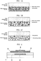
- FIG. 1A schematically illustrates a case where the ratio [C/(A+B+C)] is less than 0.21.
- FIG. 1B schematically illustrates a case where the ratio [C/(A+B+C)] is 0.21 or more but 0.78 or less.
- FIG. 1C schematically illustrates a case where the ratio [C/(A+B+C)] is more than 0.78.
- the electroconductive thin film When the electroconductive thin film is in the state of FIG. 1A , a large number of portions form an ohmic contact between the oxide semiconductor thin film and the metal oxide particles contained in the electroconductive thin film and thus the contact resistance between the electroconductive thin film and the oxide semiconductor thin film becomes low. However, the gold particles contained in the electroconductive thin film are not in contact with each other throughout the electroconductive thin film and thus the resistance of the electroconductive thin film becomes high. When the electroconductive thin film is in the state of FIG. 1C , the gold particles contained in the electroconductive thin film are in contact with each other throughout the electroconductive thin film and thus the resistance of the electroconductive thin film becomes low.
- the resistivity of the electroconductive thin film can be maintained low even when the electroconductive thin film is formed through a process performed in an oxidizing atmosphere, or a high temperature process.
- the electroconductive thin film is preferably an electroconductive thin film obtained by applying, on a support, the below-mentioned coating liquid for forming an electroconductive thin film of the present invention; drying the applied coating liquid, and baking the dried coating liquid, because an electroconductive thin film can be easily obtained, and an electroconductive thin film having a large area can be obtained.
- a shape of the electroconductive thin film is appropriately selected depending on the intended purpose without any limitation, and examples thereof include a plate, a line, and a patterned shape.
- a size of the electroconductive thin film is appropriately selected depending on the intended purpose without any limitation.
- a structure of the electroconductive thin film is appropriately selected depending on the intended purpose without any limitation, but it is preferred that the gold is dispersed in a thin film formed of the metal oxide.
- Such structure can be easily obtained by applying the below-mentioned coating liquid for forming an electroconductive thin film of the present invention onto a support, drying and then baking the applied coating liquid.
- the average thickness of the electroconductive thin film is appropriately selected depending on the intended purpose without any limitation, but it is preferably 40 nm to 2 ⁇ m, more preferably 70 nm to 1 ⁇ m.
- the average thickness can be determined by measuring a thickness of the electroconductive thin film at randomly selected 4 points thereon by means of an atomic force microscope (Nano-Im, manufactured by Pacific Nanotechnology, Inc.), and calculating an average value of the measured values.
- a production method of the electroconductive thin film is appropriately selected depending on the intended purpose without any limitation, and examples thereof include: a dry process, such as sputtering; and a wet process using a coating method, such as screen printing, roll coating, dip coating, spin coating, inkjet printing, and nano printing.
- a droplet coating method represented by an inkjet printing is preferable because an electroconductive thin film can be easily obtained, and an electroconductive thin film having a large area can be obtained.
- the electroconductive thin film can be obtained by preparing a coating liquid for forming an electroconductive thin film, applying the coating liquid for forming an electroconductive thin film onto a support, drying and then baking.
- the coating liquid for forming an electroconductive thin film for example, the below-mentioned the coating liquid for forming an electroconductive thin film of the present invention is preferable.
- the support is appropriately selected depending on the intended purpose without any limitation, and examples thereof include a glass substrate, and a plastic substrate.
- examples of the support include a substrate, a gate insulating layer, and a semiconductive layer (active layer).
- a shape, structure and size of the substrate are appropriately selected depending on the intended purpose without any limitation.
- a material of the substrate is appropriately selected depending on the intended purpose without any limitation, and examples thereof include a glass substrate, and a plastic substrate.
- the coating can be performed at room temperature.
- the support is preferably heated to about 30°C to about 100°C, the coating liquid for forming an electroconductive thin film just after deposited on a surface of the support can be prevented from wetting and spreading.
- the drying is appropriately selected depending on the intended purpose without any limitation, provided that it is performed under the conditions by which volatile components on the coating liquid for forming an electroconductive thin film can be removed. Note that, it is not necessary to completely remove the volatile components during the drying, and the volatile components may be removed in an enough amount with which baking is not adversely affected.
- the temperature of the baking is appropriately selected depending on the intended purpose without any limitation, provided that it is temperature equal to or higher than temperature at which the metal oxide (the metal oxide containing indium and thin), which is a main component of the electroconductive thin film, is formed, and equal to or lower than the deformation temperature of the support.
- the temperature of the baking is preferably 250°C to 600°C.
- the atmosphere for the baking is appropriately selected depending on the intended purpose without any limitation, and examples thereof include atmosphere including oxygen, such as in oxygen gas, and in atmosphere. Moreover, the atmosphere of the baking may be inert gas, such as nitrogen gas.
- the electric properties, reliability, and uniformity of the electroconductive thin film can be further improved.
- the duration for the baking is appropriately selected depending on the intended purpose without any limitation.
- the electroconductive thin film has low resistivity, and can realize excellent electrical connection with an oxide semiconductor film, and therefore the electroconductive thin film can be suitably used for a source electrode and drain electrode of a field-effect transistor.
- a quantitative analysis of each element contained in the electroconductive thin film can be performed by X-ray fluorescence spectroscopy in which X-rays are used for excitation of an inner-shell electron, and characteristic X-rays (fluorescent X-rays) emitted from a sample are measured. Therefore, a ratio of the numbers of atoms of elements contained in the electroconductive thin film can be determined by X-ray fluorescence spectroscopy.
- the absorption edge energy is regarded as the minimum energy required for emitting the fluorescent X-ray of the sequence (K, L, 7) thereof.
- a void is formed in an inner shell of an atom by X-rays having the energy equal to or greater than the absorption edge, and then an electron is transferred from an outer shell.
- the energy difference as caused is emitted as a fluorescent X-ray.
- a wavelength of the fluorescent X-ray is also unique to the element. Therefore, by experimentally determining a wavelength of a fluorescent X-ray of a measuring sample, elements constituting the measuring sample can be analyzed.
- the coating liquid for forming an electroconductive thin film of an example contains at least gold, and a combination of indium and tin, a metal oxide containing indium and tin, a combination of indium oxide and tin oxide, or any combination thereof, and may further contain other components, such as an organic solvent, if necessary.
- Examples of the coating liquid for forming an electroconductive thin film include: a coating liquid containing indium, tin, gold, and an organic solvent; a coating liquid containing gold, a metal oxide containing indium and tin, and organic solvent; and a coating liquid containing indium oxide, tin oxide, gold, and an organic solvent.
- the metal oxide is appropriately selected depending on the intended purpose without any limitation, provided that it contains indium and tin, but it is preferably indium tin oxide (ITO) because ITO has relatively high electroconductivity.
- ITO indium tin oxide
- a ratio of the indium and the tin is appropriately selected depending on the intended purpose without any limitation, but a ratio of the number of atoms of the tin to the number of atoms of the indium, i.e., [tin(B)/indium(A)] is preferably 0.01 to 0.25, more preferably 0.05 to 0.15.
- a shape of the metal oxide is appropriately selected depending on the intended purpose without any limitation, and examples thereof include spherical, oblate, and polyhedron. Among them, the spherical shape is preferable. Note that, the spherical shape is not limited to a sphere.
- the average particle diameter of the metal oxide is appropriately selected depending on the intended purpose without any limitation, but the upper limit thereof is preferably 1 ⁇ m or smaller, more preferably 100 nm or smaller, and even more preferably 50 nm or smaller.
- the lower limit thereof is preferably 1 nm greater, more preferably 5 nm or greater, and even more preferably 10 nm or greater.
- the average particle diameter of each type of particles in the coating liquid for forming an electroconductive thin film can be measured, for example, by means of a scanning electron microscope.
- the metal oxide may be selected from commercial products.
- Examples of the commercial products thereof include ITO nano particle dispersion liquid (of Tomoe Works Co., Ltd., average particle diameter: 20 nm, metal content: 10.1% by mass).
- the indium oxide and tin oxide are formed into a metal oxide containing indium and tin, e.g., indium tin oxide (ITO) by applying, onto a support, the coating liquid for forming an electroconductive thin film, drying, and then baking.
- ITO indium tin oxide
- a ratio of the indium and the tin is appropriately selected depending on the intended purpose without any limitation, but a ratio of the number of atoms of the tin to the number of atoms of the indium, i.e., [tin(B)/indium(A)] is preferably 0.01 to 0.25, more preferably 0.05 to 0.15.
- the gold is appropriately selected depending on the intended purpose without any limitation.
- a shape of the gold is appropriately selected depending on the intended purpose without any limitation, and examples thereof include spherical, oblate, and polyhedron. Among them, the spherical shape is preferable. Note that, the spherical shape is not limited to a sphere.
- the average particle diameter of the gold is appropriately selected depending on the intended purpose without any limitation, but the upper limit thereof is preferably 1 ⁇ m or smaller, more preferably 100 nm or smaller, and even more preferably 50 nm or smaller.
- the lower limit thereof is preferably 1 nm or greater, more preferably 5 nm or greater, and even more preferably 10 nm or greater.
- the gold may be selected from commercial products.
- Examples of the commercial products thereof include Au-1C den manufactured by ULVAC Materials Co., Ltd. (average particle diameter: 5 nm, metal content: 51% by mass), and NPG-J manufactured by Harima Chemicals Group, Inc. (average particle diameter: 7 nm, metal content: 57.5% by mass).
- metal nano particles having the average particle diameters of several nanometers to several tens nanometers are sintered at temperature that is significantly lower than the melting point thereof.
- the average particle diameter is in the aforementioned range, therefore, it can be expected that sintering temperature is lowered.
- the small average particle diameter is effective for preventing clogging of a nozzle.
- the number (A) of atoms of indium, the number (B) of atoms of tin, and the number (C) of atoms of gold in the coating liquid for forming an electroconductive thin film are appropriately selected depending on the intended purpose without any limitation, but a ratio [C/(A+B+C)] of (A), (B), and (C) is preferably 0.21 to 0.78, i.e., (A), (B), and (C) satisfy the following formula (1), because extremely low resistivity can be obtained, and excellent electrical connection with an oxide semiconductor film can be achieved. 0.21 ⁇ C / A + B + C ⁇ 0.78
- the preferable range, more preferable range, and reasons thereof are the same as the ones described in the descriptions for the electroconductive thin film.
- the organic solvent is appropriately selected depending on the intended purpose without any limitation, and examples thereof include: hydrocarbon, such as tetradecane; cyclic hydrocarbon, such as cyclohexane, and cyclododecane; and aromatic hydrocarbon, such as toluene, xylene, and mesitylene. These may be used alone, or in combination.
- An amount of the organic solvent in the coating liquid for forming an electroconductive thin film is appropriately selected depending on the intended purpose without any limitation, but it is preferably 40% by mass to 90% by mass, more preferably 50% by mass to 85% by mass. When the amount thereof is smaller than 40% by mass, the dispersed particles may be precipitated. When the amount thereof is greater than 90% by mass, a concentration of the particles is excessively low, and therefore a sufficient film thickness may not be attained. When the amount thereof is within the aforementioned more preferable range, the dispersed particles are not easily precipitated, and the intended film thickness can be easily obtained.
- the coating liquid for forming an electroconductive thin film of the present invention is suitable as a coating liquid for formation of the electroconductive thin film of the present invention.
- the coating liquid for forming an electroconductive thin film satisfying the aforementioned formula (1) is suitable as a coating liquid for formation of a source electrode and drain electrode of a field-effect transistor.
- the field-effect transistor of an example contains at least a gate electrode, a source electrode, a drain electrode, an active layer, and a gate insulating layer, and may further contain other members, if necessary.
- the field-effect transistor of the present invention can be produced, for example, by the method for producing a field-effect transistor of the present invention.
- the gate electrode is appropriately selected depending on the intended purpose without any limitation, provided that it is an electrode for applying gate voltage.
- a material of the gate electrode is appropriately selected depending on the intended purpose without any limitation, and examples thereof include: metal, such as platinum, palladium, gold, silver, copper, zinc, aluminum, nickel, chromium, tantalum, molybdenum, and titanium; an alloy of any of the above-listed metals; and a mixture of any of the above-listed metals.
- metal such as platinum, palladium, gold, silver, copper, zinc, aluminum, nickel, chromium, tantalum, molybdenum, and titanium
- an alloy of any of the above-listed metals and a mixture of any of the above-listed metals.
- electroconductive oxide such as indium oxide, zinc oxide, tin oxide, gallium oxide, and niobium oxide
- a composite compound of any of the above-listed oxide such as sodium bicarbonate
- a mixture of any of the above-listed oxide such as sodium bicarbonate
- the average thickness of the gate electrode is appropriately selected depending on the intended purpose without any limitation, but it is preferably 40 nm to 2 ⁇ m, more preferably 70 nm to 1 ⁇ m.
- the gate insulating layer is appropriately selected depending on the intended purpose without any limitation, provided that it is an insulating layer formed between the gate electrode and the active layer.
- a material of the gate insulating layer is appropriately selected depending on the intended purpose without any limitation, and examples thereof include an inorganic insulating material, and an organic insulating material.
- the inorganic insulating material examples include silicon oxide, aluminum oxide, tantalum oxide, titanium oxide, yttrium oxide, lanthanum oxide, hafnium oxide, zirconium oxide, silicon nitride, aluminum nitride, and a mixture of any of the above-listed materials.
- organic insulating material examples include polyimide, polyamide, polyacrylate, polyvinyl alcohol, and a novolak resin.
- a thickness of the gate insulating layer is appropriately selected depending on the intended purpose without any limitation, but it is preferably 50 nm to 3 ⁇ m, more preferably 100 nm to 1 ⁇ m.
- the source electrode and drain electrode are electrodes for extracting electric current, and are formed of the electroconductive thin film of the present invention.
- each of the source electrode and the drain electrode is appropriately selected depending on the intended purpose without any limitation, but it is preferably 40 nm to 2 ⁇ m, more preferably 70 nm to 1 ⁇ m.
- the active layers appropriately selected depending on the intended purpose without any limitation, provided that it is an active layer, which is formed of oxide semiconductor, and is formed between the source electrode and the drain electrode.
- oxide semiconductor examples include n-type oxide semiconductor.
- n-type oxide semiconductor examples include In-Mg oxide semiconductor, and In-Zn oxide semiconductor.
- the average thickness of the active layer is appropriately selected depending on the intended purpose without any limitation, but it is preferably 1 nm to 200 ⁇ m, more preferably 5 nm to 100 ⁇ m.
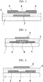
- a structure of the field-effect transistor is appropriately selected depending on the intended purpose without any limitation, and examples thereof include bottom-gate and bottom-contact ( FIG. 2 ), bottom-gate and top-contact ( FIG. 3 ), top-gate and bottom-contact ( FIG. 4 ), and top-gate and top-contact ( FIG. 5 ).
- the field-effect transistor of the present invention can be suitably used as a field-effect transistor for a pixel driving circuit and logic circuit, such as a liquid crystal display, an organic EL display, and an electrochromic display.
- the method for producing a field-effect transistor (first production method) of an example contains: forming a gate electrode on a substrate; forming a gate insulating layer on the gate electrode; forming, on the gate insulating layer, a source electrode and a drain electrode in a manner that the source electrode and the drain electrode are apart from each other; and forming an active layer formed of oxide semiconductor in an area on the gate insulating layer which is a channel region between the source electrode and the drain electrode.
- the method for producing a field-effect transistor (second production method) of the example contains: forming, on a substrate, a source electrode and a drain electrode in a manner that the source electrode and the drain electrode are apart from each other; forming an active layer formed of oxide semiconductor in an area on the substrate which is a channel region between the source electrode and the drain electrode; forming a gate insulating layer on the active layer; and forming a gate electrode on the gate insulating layer.
- the first production method will be explained hereinafter.
- a shape, structure and size of the substrate are appropriately selected depending on the intended purpose without any limitation.
- a material of the substrate is appropriately selected depending on the intended purpose without any limitation, and examples thereof include a glass substrate, and a plastic substrate.
- the glass substrate is appropriately selected depending on the intended purpose without any limitation, and examples thereof include non-alkali glass, and silica glass.
- the plastic substrate is appropriately selected depending on the intended purpose without any limitation, and examples thereof include polycarbonate (PC), polyimide (PI), polyethylene terephthalate (PET), and polyethylene naphthalate (PEN).
- PC polycarbonate
- PI polyimide
- PET polyethylene terephthalate
- PEN polyethylene naphthalate
- the substrate is preferably subjected to a pretreatment, such as oxygen plasma, UV ozone, and UV radiation washing, in order to clean a surface thereof and to improve adhesion with another layer.
- a pretreatment such as oxygen plasma, UV ozone, and UV radiation washing
- a gate electrode is appropriately selected depending on the intended purpose without any limitation, provided that it contains forming a gate electrode on the substrate, and examples thereof include: (i) forming a film by sputtering, or dip coating, followed by patterning by photolithography, and (ii) directly forming a film having an intended shape by a printing process, such as inkjet printing, nano printing, and gravure printing.
- a gate insulating layer is appropriately selected depending on the intended purpose without any limitation, provided that it is forming a gate insulating layer on the gate electrode, and examples thereof include: (i) forming a film by sputtering or dip coating, followed by patterning by photolithography; and (ii) directly forming a film having an intended shape by a printing process, such as inkjet printing, nano printing, and gravure printing.
- a source electrode and a drain electrode is appropriately selected depending on the intended purpose without any limitation, provided that it contains forming a source electrode and a drain electrode on the gate insulating layer in a manner that the source electrode and the drain electrode are apart from each other, and that the source electrode and the drain electrode are both formed by applying the coating liquid for forming an electroconductive thin film of the present invention, and are both formed of an electroconductive thin film.
- the application (coating) method is appropriately selected depending on the intended purpose without any limitation, and examples thereof include screen printing, roll coating, dip coating, spin coating, inkjet printing, and nano printing.
- the coating can be performed at room temperature.
- the support e.g., the gate insulating layer
- the coating liquid for forming an electroconductive thin film just after deposited on a surface of the support can be prevented from wetting and spreading.
- drying and baking are preferably performed.
- the drying is appropriately selected depending on the intended purpose without any limitation, provided that it is performed under the conditions by which volatile components on the coating liquid for forming an electroconductive thin film can be removed. Note that, it is not necessary to completely remove the volatile components during the drying, and the volatile components may be removed in an enough amount with which baking is not adversely affected.
- the temperature of the baking is appropriately selected depending on the intended purpose without any limitation, provided that it is temperature equal to or higher than temperature at which the metal oxide (the metal oxide containing indium and thin), which is a main component of the electroconductive thin film, is formed, and equal to or lower than the deformation temperature of the support.
- the temperature of the baking is preferably 250°C to 600°C.
- the atmosphere for the baking is appropriately selected depending on the intended purpose without any limitation, and examples thereof include atmosphere including oxygen, such as in oxygen gas, and in atmosphere. Moreover, the atmosphere of the baking may be inert gas, such as nitrogen gas.
- the electric properties, reliability, and uniformity of the electroconductive thin film can be further improved.
- the duration for the baking is appropriately selected depending on the intended purpose without any limitation.
- an active layer is appropriately selected depending on the intended purpose without any limitation, provided that it contains forming an active layer formed of oxide semiconductor in an area on the gate insulating layer which is a channel region between the source electrode and the drain electrode.
- the order for performing the formation of a source electrode and a drain electrode, and the formation of an active layer is not restricted.
- the formation of an active layer may be performed after the formation of a source electrode and a drain electrode.
- the formation of a source electrode and a drain electrode may be performed after the formation of an active layer.
- a bottom-gate and bottom-contact field-effect transistor can be produced.
- a bottom-gate and top-contact field-effect transistor can be produced.
- FIGs. 6A to 6D A production method of a bottom-gate and bottom-contact field-effect transistor will be explained with reference to FIGs. 6A to 6D , hereinafter.
- an electroconductive film e.g. aluminum
- a substrate 1 e.g., a glass substrate
- the formed electroconductive film is patterned by etching to thereby form a gate electrode 2 ( FIG. 6A ).
- a gate insulating layer 3 (e.g., SiO 2 ) is formed on the gate electrode 2 and the substrate 1 by sputtering to over the gate electrode 2 with the gate insulating layer 3 ( FIG. 6B ).
- the coating liquid for forming an electroconductive thin film is then applied onto the gate insulating layer 3, for example, by inkjet printing, and the applied coating liquid is subjected to a heat treatment, to thereby form a source electrode 4 and drain electrode 5 both formed of an electroconductive thin film ( FIG. 6C ).
- an oxide semiconductor film (e.g., In-Zn oxide semiconductor) was formed on the gate insulating layer 3 by sputtering so as to cover a channel region formed between the source electrode 4 and the drain electrode 5, and the formed oxide semiconductor film is patterned by etching to thereby form an active layer 6 ( FIG. 6D ).
- an oxide semiconductor film e.g., In-Zn oxide semiconductor
- the substrate is appropriately selected depending on the intended purpose without any limitation, and examples thereof include those substrates listed as examples in the first production method.
- a source electrode and a drain electrode is appropriately selected depending on the intended purpose without any limitation, provided that it contains forming a source electrode and a drain electrode on the substrate in a manner that the source electrode and the drain electrode are apart from each other, and that the source electrode and the drain electrode are both formed by applying the coating liquid for forming an electroconductive thin film of the present invention, and are both formed of an electroconductive thin film.
- Examples of a process thereof include those as listed in the formation of a source electrode and a drain electrode in the first production method.
- an active layer is appropriately selected depending on the intended purpose without any limitation, provided that it contains forming an active layer formed of oxide semiconductor in an area on the substrate which is a channel region between the source electrode and the drain electrode.
- a gate insulating layer is appropriately selected depending on the intended purpose without any limitation, provided that it contains forming a gate insulating layer on the active layer, and examples of a process thereof include those as listed in the formation of a gate insulating layer in the first production method.
- a gate electrode is appropriately selected depending on the intended purpose without any limitation, provided that it contains forming a gate electrode on the gate insulating layer, and examples of a process thereof include those as listed in the formation of a gate electrode in the first production method.
- the order for performing the formation of a source electrode and a drain electrode, and the formation of an active layer is not restricted.
- the formation of an active layer may be performed after the formation of a source electrode and a drain electrode.
- the formation of a source electrode and a drain electrode may be performed after the formation of an active layer.
- a top-gate and bottom-contact field-effect transistor can be produced.
- a top-gate and top-contact field-effect transistor can be produced.
- a coating liquid for forming an electroconductive thin film was prepared by mixing and stirring a commercially available ITO nanoparticle dispersion liquid (of Tomoe Works Co., Ltd., average particle diameter: 20 nm, metal content: 10.1% by mass) and gold nanometal ink (Au-lCden, manufactured by ULVAC Materials Co., Ltd., average particle diameter: 5 nm, metal content: 51% by mass).
- the ITO nanoparticle dispersion liquid and the gold metal ink were mixed to have a blending ratio of indium tin oxide (ITO) and gold as depicted in Table 1. Note that, the blending ratio was remained the same in the formed electroconductive thin film, and the ratio of the numbers of atoms thereof was as depicted in Table 1.
- E denotes "the exponent of 10.”
- 1.0E - 01 represents “0.1”
- 1.0E - 05 represents "0.00001.”
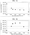
- Table 1 The values in Table 1 were plotted on a graph of FIG. 7A where the vertical axis is the volume resistivity (Qcm) of an electroconductive thin film and the horizontal axis is the ratio of the number of Au atoms. Also, they were plotted on a graph of FIG. 7B where the vertical axis is the on-state current (A) of a transistor the source electrode and drain electrode of which are both formed of an electroconductive thin film and the horizontal axis is the ratio of the number of Au atoms.
- the dotted line and the dashed-dotted line indicate acceptable values of the volume resistivity of an electroconductive thin film and the on-state current of a field-effect transistor, which are described below.
- the volume resistivity thereof is preferably 1.0E - 3 ⁇ cm or less, more preferably 2.0E - 4 ⁇ cm or less.
- the on-state current of a field-effect transistor using the electroconductive thin film of the present invention is preferably 1.0E - 4 A or more, more preferably 1.5E - 4 A or more.
- the obtained coating liquid for forming an electroconductive thin film was applied onto a glass substrate by means of an inkjet device.
- the glass substrate, on which the coating liquid for forming an electroconductive thin film had been applied was heated for 10 minutes on a hot plate of 120°C, followed by heated for 1 hour at 300°C in the atmosphere, to thereby form a linear electroconductive thin film having the average length of 4 mm, average width of 50 ⁇ m, and average thickness of 100 nm.
- a molybdenum film was formed by DC sputtering to give a thickness of about 100 nm. Thereafter, a photoresist was applied thereon, and the applied photoresist was subjected to pre-baking, exposure by an exposing device, and then developing, to thereby form a resist pattern having the same pattern as a gate electrode to be formed. Further, etching was performed using an etching liquid formed of a mixture of phosphoric acid, nitric acid, and acetic acid, to thereby remove the area of the molybdenum film where the resist pattern was not formed. Thereafter, the resist pattern is removed, to thereby form a gate electrode.
- an SiO 2 film was formed by RF sputtering to give a thickness of about 200 nm. Thereafter, a photoresist was applied thereon, and the applied photoresist was subjected to pre-baking, exposure by an exposing device, and then developing, to thereby form a resist pattern having the same pattern as a gate insulating layer to be formed. Further, etching was performed using an etching liquid using buffered hydrofluoric acid, to thereby remove the area of the SiO 2 film where the resist pattern was not formed. Thereafter, the resist pattern is removed, to thereby form a gate insulating layer.
- an In-Mg oxide thin film (average thickness: 50 nm), which would form an active layer, was formed by RF sputtering in accordance with the method described in the paragraphs [0074] to [0075] of JP-A No. 2010-74148 .
- the prepared coating liquid for forming an electroconductive thin film was applied by means of an inkjet device to give an intended pattern.
- the resultant was heated for 10 minutes on a hot plate heated at 120°C, followed by heated for 1 hour at 300°C in the atmosphere, to thereby form a source electrode and drain electrode both formed of the electroconductive thin film of the present invention.
- a channel width specified with the source electrode width was set to 400 ⁇ m
- a channel length specified with a space between the source electrode and the drain electrode was set to 50 ⁇ m.
- the volume resistivity of each of the obtained electroconductive thin films was measured by means of a semiconductor parameter analyzer 4200SCS, manufactured by Keithley Instruments Inc.
- the electric current when voltage changing from -1 V to +1 V or from +1 V to -1 V was applied at the edge of the electroconductive thin film having the length of 4 mm in the lengthwise direction was measured by a two-terminal method, to thereby measure the volume resistivity of the electroconductive thin film.
- Table 1 The results are presented in Table 1.
- the current run between the source and drain (on-state current) Ids of each of the obtained field-effect transistors was measured by means of the semiconductor parameter analyzer in which the source-drain voltage Vds was set at 20 V, and the voltage Vgs was set at 30 V. The results are presented in Table 1.
Landscapes
- Thin Film Transistor (AREA)
- Electrodes Of Semiconductors (AREA)
Claims (5)
- Elektrisch leitende Dünnschicht, die Folgendes umfasst:ein Metalloxid, das Indium und Zinn enthält; undGold, dadurch gekennzeichnet, dasseine Anzahl (A) von Atomen des Indiums, eine Anzahl (B) von Atomen des Zinns und eine Anzahl (C) von Atomen des Golds die folgende Formel (1) erfüllen:

- Beschichtungsflüssigkeit zum Bilden einer elektrisch leitenden Dünnschicht, die Folgendes umfasst:eine Kombination von Indium und Zinn, ein Metalloxid, das Indium und Zinn enthält, eine Kombination von Indiumoxid und Zinnoxid oder eine beliebige Kombination davon undGold, dadurch gekennzeichnet, dasseine Anzahl (A) von Atomen des Indiums, eine Anzahl (B) von Atomen des Zinns und eine Anzahl (C) von Atomen des Golds die folgende Formel (1) erfüllen:

- Feldeffekttransistor, der Folgendes umfasst:eine Gate-Elektrode (2);eine Source-Elektrode (4) und eine Drain-Elektrode (5);eine aktive Schicht (6), die aus einem Oxidhalbleiter gebildet ist, und die zwischen der Source-Elektrode (4) und der Drain-Elektrode (5) gebildet ist; undeine Gate-Isolierschicht (3), die zwischen der Gate-Elektrode (2) und der aktiven Schicht (6) gebildet ist, wobeisowohl die Source-Elektrode (4) als auch die Drain-Elektrode (5) aus der elektrisch leitenden Dünnschicht nach Anspruch 1 gebildet sind.
- Verfahren zum Herstellen eines Feldeffekttransistors, das Folgendes umfasst:Bilden einer Gate-Elektrode (2) auf einem Substrat (1);Bilden einer Gate-Isolierschicht (3) auf der Gate-Elektrode (2);Bilden einer Source-Elektrode (4) und einer Drain-Elektrode (5) auf der Gate-Isolierschicht (3) in der Weise, dass die Source-Elektrode (4) und die Drain-Elektrode (5) aus einer elektrisch leitenden Dünnschicht gebildet sind; undBilden einer aktiven Schicht (6), die aus einem Oxidhalbleiter gebildet ist, in einem Bereich auf der Gate-Isolierschicht (3), der ein Kanalbereich zwischen der Source-Elektrode (4) und der Drain-Elektrode (5) ist, wobeidas Bilden der Source-Elektrode (4) und der Drain-Elektrode (5) ein Aufbringen der Beschichtungsflüssigkeit enthält, um eine elektrisch leitende Dünnschicht gemäß Anspruch 2 zu bilden, um die Source-Elektrode (4) und die Drain-Elektrode (5), die beide aus der elektrisch leitenden Dünnschicht gebildet sind, zu bilden.
- Verfahren zum Herstellen eines Feldeffekttransistors, das Folgendes umfasst:Bilden auf einem Substrat (1) einer Source-Elektrode (4) und einer Drain-Elektrode (5) in der Weise, dass die Source-Elektrode (4) und die Drain-Elektrode (5) voneinander beabstandet sind;Bilden einer aktiven Schicht (6), die aus einem Oxidhalbleiter gebildet ist, in einem Bereich auf dem Substrat (1), der ein Kanalbereich zwischen der Source-Elektrode (4) und der Drain-Elektrode (5) ist;Bilden einer Gate-Isolierschicht (3) auf der aktiven Schicht (6) undBilden einer Gate-Elektrode (2) auf der Gate-Isolierschicht (3), wobeidas Bilden der Source-Elektrode (4) und der Drain-Elektrode (5) ein Aufbringen der Beschichtungsflüssigkeit umfasst, um eine elektrisch leitende Dünnschicht gemäß Anspruch 2 zu bilden, um die Source-Elektrode (4) und die Drain-Elektrode (5), die beide aus der elektrisch leitenden Dünnschicht gebildet sind, zu bilden.
Applications Claiming Priority (3)
| Application Number | Priority Date | Filing Date | Title |
|---|---|---|---|
| JP2012062117 | 2012-03-19 | ||
| JP2013044888A JP6051960B2 (ja) | 2012-03-19 | 2013-03-07 | 導電性薄膜、導電性薄膜形成用塗布液、電界効果型トランジスタ、及び電界効果型トランジスタの製造方法 |
| PCT/JP2013/058199 WO2013141330A1 (en) | 2012-03-19 | 2013-03-14 | Electroconductive thin film, coating liquid for forming electroconductive thin film, field-effect transistor, and method for producing field-effect transistor |
Publications (3)
| Publication Number | Publication Date |
|---|---|
| EP2828892A1 EP2828892A1 (de) | 2015-01-28 |
| EP2828892A4 EP2828892A4 (de) | 2015-03-04 |
| EP2828892B1 true EP2828892B1 (de) | 2019-10-16 |
Family
ID=49222782
Family Applications (1)
| Application Number | Title | Priority Date | Filing Date |
|---|---|---|---|
| EP13763600.7A Active EP2828892B1 (de) | 2012-03-19 | 2013-03-14 | Elektrisch leitfähige dünnschicht, beschichtungsflüssigkeit zur bildung der elektrisch leitfähigen dünnschicht, feldeffekttransistor und verfahren zur herstellung des feldeffekttransistors |
Country Status (7)
| Country | Link |
|---|---|
| US (1) | US9978877B2 (de) |
| EP (1) | EP2828892B1 (de) |
| JP (1) | JP6051960B2 (de) |
| KR (1) | KR101705956B1 (de) |
| CN (1) | CN104205340B (de) |
| TW (1) | TWI518796B (de) |
| WO (1) | WO2013141330A1 (de) |
Families Citing this family (14)
| Publication number | Priority date | Publication date | Assignee | Title |
|---|---|---|---|---|
| JPH0753834Y2 (ja) | 1990-09-22 | 1995-12-13 | ターボ工業株式会社 | 真空脱気装置付きローラーコンパクタのスクリューフィーダー |
| JP6672611B2 (ja) | 2014-07-03 | 2020-03-25 | 株式会社リコー | エレクトロクロミック化合物、エレクトロクロミック組成物及び表示素子及び調光素子 |
| EP3125296B1 (de) * | 2015-07-30 | 2020-06-10 | Ricoh Company, Ltd. | Feldeffekttransistor, anzeigeelement, bildanzeigevorrichtung und system |
| JP6828293B2 (ja) | 2015-09-15 | 2021-02-10 | 株式会社リコー | n型酸化物半導体膜形成用塗布液、n型酸化物半導体膜の製造方法、及び電界効果型トランジスタの製造方法 |
| US10269293B2 (en) | 2015-10-23 | 2019-04-23 | Ricoh Company, Ltd. | Field-effect transistor (FET) having gate oxide insulating layer including SI and alkaline earth elements, and display element, image display and system including FET |
| US10600916B2 (en) | 2015-12-08 | 2020-03-24 | Ricoh Company, Ltd. | Field-effect transistor, display element, image display device, and system |
| JP6607013B2 (ja) | 2015-12-08 | 2019-11-20 | 株式会社リコー | 電界効果型トランジスタ、表示素子、画像表示装置、及びシステム |
| US10170635B2 (en) | 2015-12-09 | 2019-01-01 | Ricoh Company, Ltd. | Semiconductor device, display device, display apparatus, and system |
| JP6907512B2 (ja) * | 2015-12-15 | 2021-07-21 | 株式会社リコー | 電界効果型トランジスタの製造方法 |
| JP6701835B2 (ja) | 2016-03-11 | 2020-05-27 | 株式会社リコー | 電界効果型トランジスタ、表示素子、画像表示装置、及びシステム |
| US10388738B2 (en) | 2016-04-01 | 2019-08-20 | Semiconductor Energy Laboratory Co., Ltd. | Composite oxide semiconductor and method for manufacturing the same |
| WO2019217524A1 (en) * | 2018-05-08 | 2019-11-14 | Actuated Medical, Inc. | Reduced force device for intravascular access and guidewire placement |
| JP7326795B2 (ja) | 2019-03-20 | 2023-08-16 | 株式会社リコー | 電界効果型トランジスタ、表示素子、画像表示装置、及びシステム |
| CN114725205A (zh) * | 2022-06-07 | 2022-07-08 | 惠科股份有限公司 | 阵列基板及显示面板 |
Family Cites Families (18)
| Publication number | Priority date | Publication date | Assignee | Title |
|---|---|---|---|---|
| EP0753762B1 (de) * | 1995-07-06 | 2002-03-27 | Sony Corporation | Elektrisch leitender, Antireflektionsbelag |
| JPH0973001A (ja) * | 1995-07-06 | 1997-03-18 | Sony Corp | 反射防止膜 |
| US6830823B1 (en) * | 1997-02-24 | 2004-12-14 | Superior Micropowders Llc | Gold powders, methods for producing powders and devices fabricated from same |
| JP4411672B2 (ja) * | 1997-10-23 | 2010-02-10 | 住友金属鉱山株式会社 | 透明導電層形成用塗布液とその製造方法 |
| TW432397B (en) * | 1997-10-23 | 2001-05-01 | Sumitomo Metal Mining Co | Transparent electro-conductive structure, progess for its production, transparent electro-conductive layer forming coating fluid used for its production, and process for preparing the coating fluid |
| JP4389368B2 (ja) * | 1999-12-02 | 2009-12-24 | 三菱マテリアル株式会社 | 導電性顔料粉末及びこれを用いて作られた透明導電膜 |
| US6853134B2 (en) * | 2003-05-20 | 2005-02-08 | Canon Kabushiki Kaisha | Anode structure for organic light emitting device |
| JP4254743B2 (ja) * | 2005-05-13 | 2009-04-15 | セイコーエプソン株式会社 | 薄膜トランジスタの製造方法 |
| JP4880951B2 (ja) | 2005-09-06 | 2012-02-22 | キヤノン株式会社 | 半導体素子、薄膜トランジスタ、及び薄膜ダイオード |
| KR101344483B1 (ko) * | 2007-06-27 | 2013-12-24 | 삼성전자주식회사 | 박막 트랜지스터 |
| WO2009093602A1 (ja) * | 2008-01-21 | 2009-07-30 | Nec Lcd Technologies, Ltd. | 表示装置 |
| JP5540517B2 (ja) | 2008-02-22 | 2014-07-02 | 凸版印刷株式会社 | 画像表示装置 |
| TWI508282B (zh) | 2008-08-08 | 2015-11-11 | Semiconductor Energy Lab | 半導體裝置及其製造方法 |
| JP5644071B2 (ja) | 2008-08-20 | 2014-12-24 | 株式会社リコー | 電界効果型トランジスタ、表示素子、画像表示装置及びシステム |
| JP5491833B2 (ja) | 2008-12-05 | 2014-05-14 | 株式会社半導体エネルギー研究所 | 半導体装置 |
| JP5640478B2 (ja) * | 2009-07-09 | 2014-12-17 | 株式会社リコー | 電界効果型トランジスタの製造方法及び電界効果型トランジスタ |
| JP5622457B2 (ja) * | 2010-07-01 | 2014-11-12 | 富士フイルム株式会社 | 薄膜トランジスタおよびその製造方法 |
| EP2426720A1 (de) | 2010-09-03 | 2012-03-07 | Applied Materials, Inc. | Versetzter Dünnfilmtransistor und Herstellungsverfahren dafür |
-
2013
- 2013-03-07 JP JP2013044888A patent/JP6051960B2/ja active Active
- 2013-03-14 WO PCT/JP2013/058199 patent/WO2013141330A1/en not_active Ceased
- 2013-03-14 KR KR1020147027310A patent/KR101705956B1/ko active Active
- 2013-03-14 CN CN201380015030.3A patent/CN104205340B/zh active Active
- 2013-03-14 EP EP13763600.7A patent/EP2828892B1/de active Active
- 2013-03-14 US US14/382,604 patent/US9978877B2/en active Active
- 2013-03-18 TW TW102109480A patent/TWI518796B/zh active
Non-Patent Citations (1)
| Title |
|---|
| None * |
Also Published As
| Publication number | Publication date |
|---|---|
| KR20140141617A (ko) | 2014-12-10 |
| EP2828892A4 (de) | 2015-03-04 |
| CN104205340A (zh) | 2014-12-10 |
| US9978877B2 (en) | 2018-05-22 |
| WO2013141330A1 (en) | 2013-09-26 |
| EP2828892A1 (de) | 2015-01-28 |
| JP6051960B2 (ja) | 2016-12-27 |
| JP2013225666A (ja) | 2013-10-31 |
| KR101705956B1 (ko) | 2017-02-22 |
| TWI518796B (zh) | 2016-01-21 |
| US20150028334A1 (en) | 2015-01-29 |
| CN104205340B (zh) | 2018-03-06 |
| TW201340219A (zh) | 2013-10-01 |
Similar Documents
| Publication | Publication Date | Title |
|---|---|---|
| EP2828892B1 (de) | Elektrisch leitfähige dünnschicht, beschichtungsflüssigkeit zur bildung der elektrisch leitfähigen dünnschicht, feldeffekttransistor und verfahren zur herstellung des feldeffekttransistors | |
| US8202760B2 (en) | Method for manufacturing an organic semiconductor element | |
| EP2786405B1 (de) | Beschichtungsflüssigkeit zur herstellung einer metalloxid-dünnschicht und verfahren zur herstellung eines feldeffekttransistors | |
| CN101884110B (zh) | 氧化物半导体薄膜晶体管 | |
| CN102097487B (zh) | 氧化物半导体薄膜晶体管及其制造方法 | |
| US8013331B2 (en) | Thin film transistor, method of manufacturing the same, and electronic device using the same | |
| US9236454B2 (en) | Method of manufacturing thin-film transistor, thin-film transistor, display apparatus, sensor, and digital X-ray image-capturing apparatus | |
| CN102623344B (zh) | 底栅型薄膜晶体管、其制造方法及显示装置 | |
| CN108538919A (zh) | 薄膜晶体管 | |
| US7872254B2 (en) | Wiring and organic transistor, and manufacturing method thereof | |
| US20080087883A1 (en) | Organic Transistor Using Self-Assembled Monolayer | |
| US20100244017A1 (en) | Thin-film transistor (tft) with an extended oxide channel | |
| US9564481B2 (en) | Fully-printed carbon nanotube thin film transistor circuits for organic light emitting diode | |
| KR20110005223A (ko) | 전계 효과 트랜지스터 및 전계 효과 트랜지스터의 제조 방법 | |
| JP5795551B2 (ja) | 電界効果型トランジスタの製造方法 | |
| US8525175B2 (en) | Electronic device having an isolating element and display apparatus including the electronic device | |
| Jeon et al. | Contact properties of a low-resistance aluminum-based electrode with metal capping layers in vertical oxide thin-film transistors | |
| JPWO2010053171A1 (ja) | スイッチング素子及びその製造方法 | |
| Luo et al. | Contact‐Engineering of Self‐Aligned‐Gate Metal Oxide Transistors Processed via Electrode Self‐Delamination and Rapid Photonic Curing | |
| JP2010205932A (ja) | 電界効果型トランジスタ | |
| TWI776995B (zh) | 氧化物半導體薄膜、薄膜電晶體、薄膜電晶體之製造方法及濺鍍靶 | |
| Priyadarsini et al. | Excellent Positive Bias‐Stress Stability of Electrolyte‐Gated Amorphous Oxide Transistors for Long‐Term Stable High‐Power Applications | |
| JP2010056408A (ja) | アルミニウム含有有機化合物溶液、電界効果型トランジスタ及び電界効果型トランジスタの作製方法 |
Legal Events
| Date | Code | Title | Description |
|---|---|---|---|
| PUAI | Public reference made under article 153(3) epc to a published international application that has entered the european phase |
Free format text: ORIGINAL CODE: 0009012 |
|
| 17P | Request for examination filed |
Effective date: 20140910 |
|
| AK | Designated contracting states |
Kind code of ref document: A1 Designated state(s): AL AT BE BG CH CY CZ DE DK EE ES FI FR GB GR HR HU IE IS IT LI LT LU LV MC MK MT NL NO PL PT RO RS SE SI SK SM TR |
|
| AX | Request for extension of the european patent |
Extension state: BA ME |
|
| A4 | Supplementary search report drawn up and despatched |
Effective date: 20150203 |
|
| RIC1 | Information provided on ipc code assigned before grant |
Ipc: H01L 29/45 20060101ALI20150128BHEP Ipc: G02F 1/1368 20060101ALI20150128BHEP Ipc: H01L 27/12 20060101ALI20150128BHEP Ipc: H01L 21/336 20060101ALI20150128BHEP Ipc: H01L 23/532 20060101ALI20150128BHEP Ipc: H01L 21/768 20060101ALI20150128BHEP Ipc: H01L 29/417 20060101ALI20150128BHEP Ipc: H01L 21/28 20060101ALI20150128BHEP Ipc: H01L 21/288 20060101ALI20150128BHEP Ipc: H01L 29/786 20060101AFI20150128BHEP Ipc: H01L 21/3205 20060101ALI20150128BHEP |
|
| DAX | Request for extension of the european patent (deleted) | ||
| REG | Reference to a national code |
Ref country code: DE Ref legal event code: R079 Ref document number: 602013061788 Country of ref document: DE Free format text: PREVIOUS MAIN CLASS: H01L0029786000 Ipc: H01L0021445000 |
|
| RIC1 | Information provided on ipc code assigned before grant |
Ipc: H01L 21/445 20060101AFI20180917BHEP Ipc: H01L 27/12 20060101ALI20180917BHEP Ipc: H01L 29/786 20060101ALI20180917BHEP Ipc: H01L 23/532 20060101ALI20180917BHEP Ipc: H01L 29/45 20060101ALI20180917BHEP |
|
| GRAP | Despatch of communication of intention to grant a patent |
Free format text: ORIGINAL CODE: EPIDOSNIGR1 |
|
| STAA | Information on the status of an ep patent application or granted ep patent |
Free format text: STATUS: GRANT OF PATENT IS INTENDED |
|
| INTG | Intention to grant announced |
Effective date: 20190102 |
|
| GRAJ | Information related to disapproval of communication of intention to grant by the applicant or resumption of examination proceedings by the epo deleted |
Free format text: ORIGINAL CODE: EPIDOSDIGR1 |
|
| STAA | Information on the status of an ep patent application or granted ep patent |
Free format text: STATUS: REQUEST FOR EXAMINATION WAS MADE |
|
| GRAP | Despatch of communication of intention to grant a patent |
Free format text: ORIGINAL CODE: EPIDOSNIGR1 |
|
| STAA | Information on the status of an ep patent application or granted ep patent |
Free format text: STATUS: GRANT OF PATENT IS INTENDED |
|
| INTG | Intention to grant announced |
Effective date: 20190517 |
|
| GRAS | Grant fee paid |
Free format text: ORIGINAL CODE: EPIDOSNIGR3 |
|
| GRAA | (expected) grant |
Free format text: ORIGINAL CODE: 0009210 |
|
| STAA | Information on the status of an ep patent application or granted ep patent |
Free format text: STATUS: THE PATENT HAS BEEN GRANTED |
|
| AK | Designated contracting states |
Kind code of ref document: B1 Designated state(s): AL AT BE BG CH CY CZ DE DK EE ES FI FR GB GR HR HU IE IS IT LI LT LU LV MC MK MT NL NO PL PT RO RS SE SI SK SM TR |
|
| REG | Reference to a national code |
Ref country code: GB Ref legal event code: FG4D |
|
| REG | Reference to a national code |
Ref country code: CH Ref legal event code: EP |
|
| REG | Reference to a national code |
Ref country code: DE Ref legal event code: R096 Ref document number: 602013061788 Country of ref document: DE |
|
| REG | Reference to a national code |
Ref country code: IE Ref legal event code: FG4D |
|
| REG | Reference to a national code |
Ref country code: AT Ref legal event code: REF Ref document number: 1192122 Country of ref document: AT Kind code of ref document: T Effective date: 20191115 |
|
| REG | Reference to a national code |
Ref country code: NL Ref legal event code: MP Effective date: 20191016 |
|
| REG | Reference to a national code |
Ref country code: LT Ref legal event code: MG4D |
|
| REG | Reference to a national code |
Ref country code: AT Ref legal event code: MK05 Ref document number: 1192122 Country of ref document: AT Kind code of ref document: T Effective date: 20191016 |
|
| PG25 | Lapsed in a contracting state [announced via postgrant information from national office to epo] |
Ref country code: LV Free format text: LAPSE BECAUSE OF FAILURE TO SUBMIT A TRANSLATION OF THE DESCRIPTION OR TO PAY THE FEE WITHIN THE PRESCRIBED TIME-LIMIT Effective date: 20191016 Ref country code: SE Free format text: LAPSE BECAUSE OF FAILURE TO SUBMIT A TRANSLATION OF THE DESCRIPTION OR TO PAY THE FEE WITHIN THE PRESCRIBED TIME-LIMIT Effective date: 20191016 Ref country code: AT Free format text: LAPSE BECAUSE OF FAILURE TO SUBMIT A TRANSLATION OF THE DESCRIPTION OR TO PAY THE FEE WITHIN THE PRESCRIBED TIME-LIMIT Effective date: 20191016 Ref country code: BG Free format text: LAPSE BECAUSE OF FAILURE TO SUBMIT A TRANSLATION OF THE DESCRIPTION OR TO PAY THE FEE WITHIN THE PRESCRIBED TIME-LIMIT Effective date: 20200116 Ref country code: FI Free format text: LAPSE BECAUSE OF FAILURE TO SUBMIT A TRANSLATION OF THE DESCRIPTION OR TO PAY THE FEE WITHIN THE PRESCRIBED TIME-LIMIT Effective date: 20191016 Ref country code: PT Free format text: LAPSE BECAUSE OF FAILURE TO SUBMIT A TRANSLATION OF THE DESCRIPTION OR TO PAY THE FEE WITHIN THE PRESCRIBED TIME-LIMIT Effective date: 20200217 Ref country code: NO Free format text: LAPSE BECAUSE OF FAILURE TO SUBMIT A TRANSLATION OF THE DESCRIPTION OR TO PAY THE FEE WITHIN THE PRESCRIBED TIME-LIMIT Effective date: 20200116 Ref country code: PL Free format text: LAPSE BECAUSE OF FAILURE TO SUBMIT A TRANSLATION OF THE DESCRIPTION OR TO PAY THE FEE WITHIN THE PRESCRIBED TIME-LIMIT Effective date: 20191016 Ref country code: LT Free format text: LAPSE BECAUSE OF FAILURE TO SUBMIT A TRANSLATION OF THE DESCRIPTION OR TO PAY THE FEE WITHIN THE PRESCRIBED TIME-LIMIT Effective date: 20191016 Ref country code: GR Free format text: LAPSE BECAUSE OF FAILURE TO SUBMIT A TRANSLATION OF THE DESCRIPTION OR TO PAY THE FEE WITHIN THE PRESCRIBED TIME-LIMIT Effective date: 20200117 Ref country code: NL Free format text: LAPSE BECAUSE OF FAILURE TO SUBMIT A TRANSLATION OF THE DESCRIPTION OR TO PAY THE FEE WITHIN THE PRESCRIBED TIME-LIMIT Effective date: 20191016 Ref country code: ES Free format text: LAPSE BECAUSE OF FAILURE TO SUBMIT A TRANSLATION OF THE DESCRIPTION OR TO PAY THE FEE WITHIN THE PRESCRIBED TIME-LIMIT Effective date: 20191016 |
|
| PG25 | Lapsed in a contracting state [announced via postgrant information from national office to epo] |
Ref country code: RS Free format text: LAPSE BECAUSE OF FAILURE TO SUBMIT A TRANSLATION OF THE DESCRIPTION OR TO PAY THE FEE WITHIN THE PRESCRIBED TIME-LIMIT Effective date: 20191016 Ref country code: HR Free format text: LAPSE BECAUSE OF FAILURE TO SUBMIT A TRANSLATION OF THE DESCRIPTION OR TO PAY THE FEE WITHIN THE PRESCRIBED TIME-LIMIT Effective date: 20191016 Ref country code: IS Free format text: LAPSE BECAUSE OF FAILURE TO SUBMIT A TRANSLATION OF THE DESCRIPTION OR TO PAY THE FEE WITHIN THE PRESCRIBED TIME-LIMIT Effective date: 20200224 |
|
| PG25 | Lapsed in a contracting state [announced via postgrant information from national office to epo] |
Ref country code: AL Free format text: LAPSE BECAUSE OF FAILURE TO SUBMIT A TRANSLATION OF THE DESCRIPTION OR TO PAY THE FEE WITHIN THE PRESCRIBED TIME-LIMIT Effective date: 20191016 |
|
| REG | Reference to a national code |
Ref country code: DE Ref legal event code: R097 Ref document number: 602013061788 Country of ref document: DE |
|
| PG2D | Information on lapse in contracting state deleted |
Ref country code: IS |
|
| PG25 | Lapsed in a contracting state [announced via postgrant information from national office to epo] |
Ref country code: RO Free format text: LAPSE BECAUSE OF FAILURE TO SUBMIT A TRANSLATION OF THE DESCRIPTION OR TO PAY THE FEE WITHIN THE PRESCRIBED TIME-LIMIT Effective date: 20191016 Ref country code: EE Free format text: LAPSE BECAUSE OF FAILURE TO SUBMIT A TRANSLATION OF THE DESCRIPTION OR TO PAY THE FEE WITHIN THE PRESCRIBED TIME-LIMIT Effective date: 20191016 Ref country code: CZ Free format text: LAPSE BECAUSE OF FAILURE TO SUBMIT A TRANSLATION OF THE DESCRIPTION OR TO PAY THE FEE WITHIN THE PRESCRIBED TIME-LIMIT Effective date: 20191016 Ref country code: DK Free format text: LAPSE BECAUSE OF FAILURE TO SUBMIT A TRANSLATION OF THE DESCRIPTION OR TO PAY THE FEE WITHIN THE PRESCRIBED TIME-LIMIT Effective date: 20191016 Ref country code: IS Free format text: LAPSE BECAUSE OF FAILURE TO SUBMIT A TRANSLATION OF THE DESCRIPTION OR TO PAY THE FEE WITHIN THE PRESCRIBED TIME-LIMIT Effective date: 20200216 |
|
| PLBE | No opposition filed within time limit |
Free format text: ORIGINAL CODE: 0009261 |
|
| STAA | Information on the status of an ep patent application or granted ep patent |
Free format text: STATUS: NO OPPOSITION FILED WITHIN TIME LIMIT |
|
| PG25 | Lapsed in a contracting state [announced via postgrant information from national office to epo] |
Ref country code: SK Free format text: LAPSE BECAUSE OF FAILURE TO SUBMIT A TRANSLATION OF THE DESCRIPTION OR TO PAY THE FEE WITHIN THE PRESCRIBED TIME-LIMIT Effective date: 20191016 Ref country code: SM Free format text: LAPSE BECAUSE OF FAILURE TO SUBMIT A TRANSLATION OF THE DESCRIPTION OR TO PAY THE FEE WITHIN THE PRESCRIBED TIME-LIMIT Effective date: 20191016 Ref country code: IT Free format text: LAPSE BECAUSE OF FAILURE TO SUBMIT A TRANSLATION OF THE DESCRIPTION OR TO PAY THE FEE WITHIN THE PRESCRIBED TIME-LIMIT Effective date: 20191016 |
|
| 26N | No opposition filed |
Effective date: 20200717 |
|
| PG25 | Lapsed in a contracting state [announced via postgrant information from national office to epo] |
Ref country code: MC Free format text: LAPSE BECAUSE OF FAILURE TO SUBMIT A TRANSLATION OF THE DESCRIPTION OR TO PAY THE FEE WITHIN THE PRESCRIBED TIME-LIMIT Effective date: 20191016 |
|
| REG | Reference to a national code |
Ref country code: CH Ref legal event code: PL |
|
| PG25 | Lapsed in a contracting state [announced via postgrant information from national office to epo] |
Ref country code: SI Free format text: LAPSE BECAUSE OF FAILURE TO SUBMIT A TRANSLATION OF THE DESCRIPTION OR TO PAY THE FEE WITHIN THE PRESCRIBED TIME-LIMIT Effective date: 20191016 |
|
| REG | Reference to a national code |
Ref country code: BE Ref legal event code: MM Effective date: 20200331 |
|
| PG25 | Lapsed in a contracting state [announced via postgrant information from national office to epo] |
Ref country code: LU Free format text: LAPSE BECAUSE OF NON-PAYMENT OF DUE FEES Effective date: 20200314 |
|
| PG25 | Lapsed in a contracting state [announced via postgrant information from national office to epo] |
Ref country code: CH Free format text: LAPSE BECAUSE OF NON-PAYMENT OF DUE FEES Effective date: 20200331 Ref country code: LI Free format text: LAPSE BECAUSE OF NON-PAYMENT OF DUE FEES Effective date: 20200331 Ref country code: IE Free format text: LAPSE BECAUSE OF NON-PAYMENT OF DUE FEES Effective date: 20200314 |
|
| PG25 | Lapsed in a contracting state [announced via postgrant information from national office to epo] |
Ref country code: BE Free format text: LAPSE BECAUSE OF NON-PAYMENT OF DUE FEES Effective date: 20200331 |
|
| PG25 | Lapsed in a contracting state [announced via postgrant information from national office to epo] |
Ref country code: TR Free format text: LAPSE BECAUSE OF FAILURE TO SUBMIT A TRANSLATION OF THE DESCRIPTION OR TO PAY THE FEE WITHIN THE PRESCRIBED TIME-LIMIT Effective date: 20191016 Ref country code: MT Free format text: LAPSE BECAUSE OF FAILURE TO SUBMIT A TRANSLATION OF THE DESCRIPTION OR TO PAY THE FEE WITHIN THE PRESCRIBED TIME-LIMIT Effective date: 20191016 Ref country code: CY Free format text: LAPSE BECAUSE OF FAILURE TO SUBMIT A TRANSLATION OF THE DESCRIPTION OR TO PAY THE FEE WITHIN THE PRESCRIBED TIME-LIMIT Effective date: 20191016 |
|
| PG25 | Lapsed in a contracting state [announced via postgrant information from national office to epo] |
Ref country code: MK Free format text: LAPSE BECAUSE OF FAILURE TO SUBMIT A TRANSLATION OF THE DESCRIPTION OR TO PAY THE FEE WITHIN THE PRESCRIBED TIME-LIMIT Effective date: 20191016 |
|
| P01 | Opt-out of the competence of the unified patent court (upc) registered |
Effective date: 20230522 |
|
| PGFP | Annual fee paid to national office [announced via postgrant information from national office to epo] |
Ref country code: DE Payment date: 20240320 Year of fee payment: 12 Ref country code: GB Payment date: 20240320 Year of fee payment: 12 |
|
| PGFP | Annual fee paid to national office [announced via postgrant information from national office to epo] |
Ref country code: FR Payment date: 20240328 Year of fee payment: 12 |
|
| REG | Reference to a national code |
Ref country code: DE Ref legal event code: R119 Ref document number: 602013061788 Country of ref document: DE |
|
| GBPC | Gb: european patent ceased through non-payment of renewal fee |
Effective date: 20250314 |
|
| PG25 | Lapsed in a contracting state [announced via postgrant information from national office to epo] |
Ref country code: DE Free format text: LAPSE BECAUSE OF NON-PAYMENT OF DUE FEES Effective date: 20251001 |
|
| PG25 | Lapsed in a contracting state [announced via postgrant information from national office to epo] |
Ref country code: GB Free format text: LAPSE BECAUSE OF NON-PAYMENT OF DUE FEES Effective date: 20250314 |
|
| PG25 | Lapsed in a contracting state [announced via postgrant information from national office to epo] |
Ref country code: FR Free format text: LAPSE BECAUSE OF NON-PAYMENT OF DUE FEES Effective date: 20250331 |