EP2828423B1 - Carrier element for a compaction device - Google Patents
Carrier element for a compaction device Download PDFInfo
- Publication number
- EP2828423B1 EP2828423B1 EP13716361.4A EP13716361A EP2828423B1 EP 2828423 B1 EP2828423 B1 EP 2828423B1 EP 13716361 A EP13716361 A EP 13716361A EP 2828423 B1 EP2828423 B1 EP 2828423B1
- Authority
- EP
- European Patent Office
- Prior art keywords
- suction
- carrier element
- shaft
- shells
- shell
- Prior art date
- Legal status (The legal status is an assumption and is not a legal conclusion. Google has not performed a legal analysis and makes no representation as to the accuracy of the status listed.)
- Active
Links
- 238000005056 compaction Methods 0.000 title claims description 6
- 238000009987 spinning Methods 0.000 claims description 14
- 230000009467 reduction Effects 0.000 claims description 6
- 238000007378 ring spinning Methods 0.000 claims description 5
- 230000001154 acute effect Effects 0.000 claims description 2
- 239000003570 air Substances 0.000 description 39
- 230000006835 compression Effects 0.000 description 23
- 238000007906 compression Methods 0.000 description 23
- 239000000835 fiber Substances 0.000 description 16
- 239000002657 fibrous material Substances 0.000 description 13
- 230000002093 peripheral effect Effects 0.000 description 9
- 238000005304 joining Methods 0.000 description 8
- 238000004519 manufacturing process Methods 0.000 description 7
- 238000007789 sealing Methods 0.000 description 7
- 230000008878 coupling Effects 0.000 description 4
- 238000010168 coupling process Methods 0.000 description 4
- 238000005859 coupling reaction Methods 0.000 description 4
- 238000013461 design Methods 0.000 description 4
- 238000002347 injection Methods 0.000 description 4
- 239000007924 injection Substances 0.000 description 4
- 238000009434 installation Methods 0.000 description 4
- 238000004140 cleaning Methods 0.000 description 3
- 230000000694 effects Effects 0.000 description 3
- 238000000926 separation method Methods 0.000 description 3
- 239000000853 adhesive Substances 0.000 description 2
- 230000001070 adhesive effect Effects 0.000 description 2
- 239000012080 ambient air Substances 0.000 description 2
- 230000004888 barrier function Effects 0.000 description 2
- 239000000356 contaminant Substances 0.000 description 2
- 238000006073 displacement reaction Methods 0.000 description 2
- 239000004519 grease Substances 0.000 description 2
- 238000009420 retrofitting Methods 0.000 description 2
- 238000012546 transfer Methods 0.000 description 2
- 230000007704 transition Effects 0.000 description 2
- 238000009825 accumulation Methods 0.000 description 1
- 230000009471 action Effects 0.000 description 1
- 239000000654 additive Substances 0.000 description 1
- 238000005452 bending Methods 0.000 description 1
- 238000004891 communication Methods 0.000 description 1
- 238000000280 densification Methods 0.000 description 1
- 238000009826 distribution Methods 0.000 description 1
- 239000000428 dust Substances 0.000 description 1
- 239000013013 elastic material Substances 0.000 description 1
- 239000012535 impurity Substances 0.000 description 1
- 239000000463 material Substances 0.000 description 1
- 238000012544 monitoring process Methods 0.000 description 1
- 229920003023 plastic Polymers 0.000 description 1
- 238000012545 processing Methods 0.000 description 1
- 239000000243 solution Substances 0.000 description 1
- 230000000007 visual effect Effects 0.000 description 1
- 238000003466 welding Methods 0.000 description 1
Images

Classifications
-
- D—TEXTILES; PAPER
- D01—NATURAL OR MAN-MADE THREADS OR FIBRES; SPINNING
- D01H—SPINNING OR TWISTING
- D01H5/00—Drafting machines or arrangements ; Threading of roving into drafting machine
- D01H5/18—Drafting machines or arrangements without fallers or like pinned bars
- D01H5/22—Drafting machines or arrangements without fallers or like pinned bars in which fibres are controlled by rollers only
-
- D—TEXTILES; PAPER
- D01—NATURAL OR MAN-MADE THREADS OR FIBRES; SPINNING
- D01H—SPINNING OR TWISTING
- D01H5/00—Drafting machines or arrangements ; Threading of roving into drafting machine
- D01H5/18—Drafting machines or arrangements without fallers or like pinned bars
- D01H5/70—Constructional features of drafting elements
- D01H5/72—Fibre-condensing guides
-
- D—TEXTILES; PAPER
- D01—NATURAL OR MAN-MADE THREADS OR FIBRES; SPINNING
- D01H—SPINNING OR TWISTING
- D01H5/00—Drafting machines or arrangements ; Threading of roving into drafting machine
- D01H5/18—Drafting machines or arrangements without fallers or like pinned bars
- D01H5/70—Constructional features of drafting elements
- D01H5/74—Rollers or roller bearings
Definitions
- the invention relates to a support element for a compression device for two juxtaposed drafting units of a spinning machine according to the preamble of claim 1.
- a variety of designs are already known, for compacting (compacting) of the votes of a drafting unit fiber material (fiber strand) downstream of a compacting device.
- a swirl-generating device is supplied.
- Such a swirl generating device consists for. Example, in a ring spinning machine from a rotor which rotates on a ring, wherein the yarn produced is wound on a rotating sleeve.
- compression means are substantially evacuated circumferential, perforated suction drums or circumferential, provided with perforations straps used.
- a special suction region is defined on the compression element using corresponding inserts within the suction drum, or within the circumferential straps.
- Such inserts can be z. B. are provided with correspondingly shaped suction slots, to which a negative pressure is applied, whereby a corresponding air flow is generated at the periphery of the respective compression element.
- the fiber material discharged by the drafting unit is guided above or else below the compacting devices used.
- Such devices are z. B. in the publications EP 947 614 B1 . DE 10 2005 010 903 A1 . DE 198 46 268 C2 . EP 1 612 309 B1 . DE 100 18 480 A1 and the CN 1712588 A shown and described.
- the publications mentioned above are essentially permanently installed compression devices, which are permanently installed following the respective drafting system. The drive of these compaction devices takes place partly via special, arranged over the length of the spinning machine drive shafts, which are either in drive connection with a suction roll or a rotating belt or permanently installed drive connection to correspondingly arranged pressure rollers of the compression device.
- Out DE10210054850A1 is a compressor device for arrangement in a drafting system downstream compressor zone known. It has at least one wear-trained system part, which is supported in its working position against a rotating roller of the drafting system, and at least one holding part, with which the system part held in its working position and / or axially and radially fixed with respect to the roller, wherein the system part and the holding part are at least positively and reversibly releasably connected to each other firmly.
- a compaction roller are received with a rotation locking roller in a bearing element, which is connected via a plate via screws with a pivotable loading arm of a drafting device.
- the drive is transmitted via friction from a directly connected to a drive output roller and its associated pressure roller on the compression roller and the rotation locking roller.
- the compacting device shown here is also intended for retrofitting to existing drafting equipment of spinning machines without compression.
- the attachment of the compression unit shown here to an existing drafting unit via a screw, as well as the threading at the axis of the pressure roller is relatively time consuming and requires an additional Einjusttechnik the distances. Similarly, the connection to a vacuum source must be made separately.
- the suction elements which are associated with a defined compression area for compressing the fiber material, are acted upon by additionally arranged lines, which are connected to a vacuum source, with a negative pressure.
- the WO2012068693 proposed an embodiment, wherein the compression element in the form of a suction drum and the pinch roller on a common support (support member) are rotatably mounted, which is fastened via fastening means on the spinning machine removable.
- the compacting device is pivoted about the support member about a pivot axis in the direction of the output roller pair of the drafting system, in each case a coaxially mounted on the respective suction drum friction wheel with the lower roller of the output roller pair of the drafting system takes a frictional connection (via friction).
- spring elements eg on the loading arm of the drafting system
- the support member is provided in the present example for the rotatable mounting of two coaxial and juxtaposed suction drums, which are attached to two adjacent drafting units, a so-called twin drafting. Under a twin drafting two adjacent drafting units are to be understood, the pressure rollers are loaded via a common pressure arm.
- a suction channel for applying a negative pressure to the compression elements is provided within the support element (carrier).
- a first end of the suction channel communicates with the respective compression element and its second end terminates in the region of the support element with which the support element is fastened in its mounted position on the spinning machine.
- the second end of the suction channel within the support element forms a coupling point for the connection of a further air channel, which is in communication with a main channel.
- the support element serves on the one hand as a receptacle and bearing element for the compression elements (eg rotatably mounted suction drums with permanently installed suction inserts) and on the other hand as a channel for applying a negative air pressure to the corresponding suction inserts of the compression units.
- the compression elements eg rotatably mounted suction drums with permanently installed suction inserts
- the invention is now based on the object, in the WO2012068693 shown and described support member with compression devices for two side by side arranged to simplify and improve arranged drafting units to ensure a simplified and cost-effective production. Likewise, the assembly of the attached to the support member shaft for the rotatable mounting of the suction drums should be simplified.
- outwardly projecting suction insert means that the suction insert of the respective half-shell extends transversely to the longitudinal direction and away from the suction channel of the half-shell, or of the conveying channel.
- the shaft is provided with two end portions, which have a smaller diameter relative to a central region of the shaft and the passage opening of the bearing element of the respective suction insert is provided with a stepped reduction in their inside diameter, wherein the, with the larger clear width provided portions of the passage openings adjoin one another coaxially and the, provided with a larger diameter than the reduced inside diameter of the passage opening central portion of the shaft within said, adjacent sections between abutment surfaces of the respective stepped reduction of the passage openings in the axial direction is fixed.
- the support element of two half-shells which can be connected to one another, its manufacture is simplified, whereby it is made possible for the half-shells to be produced as simple injection-molded parts.
- the, connected to the respective half-shell, tubular suction insert can be made in the same operation.
- suction inserts are aligned coaxially with each other.
- the shaft in the radial direction superimposed recording of the respective suction insert the shaft which is provided for rotatably supporting the suction drums, at the same time fixed in the axial direction when joining the two half-shells.
- the respective half shell of the support element and its associated suction insert form a one-piece, stable unit.
- the bearing elements are provided for radially fixing the shaft in the region of the stepped diameter reduction with coaxial with the respective passage opening recesses, the base of the respective recess serves as a stop surface for the axial fixation of the central part of the shaft and in the circumferential direction of the Deepening the middle part of the shaft fixed in the radial direction. That is, the diameter of the central portion of the shaft corresponds to the clear width of the recess and is held in this via a clearance in the radial direction.
- the proposed design of the support element enables a simple manufacturing process and at the same time simplifies the assembly of the elements connected to the support element (eg the shaft for the suction drums).
- the two half-shells are each provided with an opening for receiving a respective suction tube, which are associated with the respective suction drum, wherein the center axes of the openings in the mounted state of the support element are aligned coaxially with each other and their coaxial common axis in one parallel distance to the axis of the suction drums superimposed shaft.
- the openings open in each case in the edge region of the suction channel.
- the respective half-shell is provided with projecting to the center of the suction channel webs which extend axially and in extension to the respective opening on the side of the opening which faces the suction drums.
- the suction pipes are removably attached to the respective opening.
- This makes it possible different suction tubes as needed against each other exchange.
- the production of the two half-shells of the support element can take place without consideration of complicated injection molds, which are necessary if the suction tubes were firmly connected to the half-shells.
- the central axis of the respective suction pipe at an angle to the axis of the suction drum supporting shaft. This increases, starting from the outer suction opening of the suction tube in the direction of the opening of the half-shell, the distance between the respective suction tube and, the suction tube opposite suction drum.
- the space between the respective suction pipes and the respective suction drum can be kept so large, so that no deposits can form in this area by fiber fly.
- the suction tubes are provided with elevations and / or depressions via which they form a positive connection in the circumferential direction with elevations and / or depressions in the region of the opening of the half-shell form.
- the outer suction openings of the suction tubes lie in planes which, viewed in the horizontal direction and in the suction direction of the fiber channel, form an acute angle and move toward one another above the suction channel in the vertical direction.
- the suction opening in the space obliquely oriented suction openings an optimal suction effect is achieved with respect to the thread path, whereby a broken thread end can be quickly detected and fed to the suction channel.
- the suction opening could also be partially behind the yarn course (as seen in front view of the compacting device).
- the bearing elements of the two suction inserts of the half shells each have an additional radial support for the shaft, which is provided adjacent in the region in which the half shells lie in the mounted position to each other.
- At least one of the radial supports forms a positive connection in the half shells with the shaft, seen in the circumferential direction of the shaft. This ensures that only the suction drums mounted on the shaft via bearings rotate and the shaft stops and thus no wear occurs between the shaft and its radial supports in the bearing element.
- the shaft is provided in the region of the bearing points for the respective suction drum for the passage of air with a longitudinally aligned flattening. This allows the suction air flow in the area of the flattening of the shaft to be routed past the grease-lubricated bearings. Without such a bypass created by the proposed flattening, it may happen that the grease is forced out of the bearings by the suction air flow, which may settle on parts of the shaft or half shells. As a result, located in the suction air flow fibers can be held in the areas where the fat adheres, which can lead to blockages.
- the half shells are made of a transparent plastic material.
- the respective suction insert of the half-shells is provided with a, running on the outer circumference of the suction insert recess which in the region between the end face of the respective half-shell, with which they lie against each other and the respective, the suction insert superior face of the suction drum is arranged.
- lamellar gradations in the area of the surfaces with which the two half-shells abut each other during assembly (assembly), lamellar gradations (spring / groove principle) may be provided in order to seal off the suction channel formed by the two half-shells from the ambient air. If necessary, even circumferential sealing elements can be used.
- the sucked through the suction slots air is fed directly to the suction channel without further deflection, so that the air can be sucked without disturbing air vortex.
- connection of the two half shells wherein the two half shells are each provided with a circumferential flange, wherein - viewed in the mounted position of the two half shells - the flange of the second half shell partially surmounted the first half shell and the flange of the first Half shell completely surmounted the flange of the second half-shell and forms a positive clamping connection with this.
- This provides a connection without the use of additional connecting means (eg screws, rivets, etc.) while at the same time sealing the interior from the environment.
- the flange of the second half-shell is provided with an inwardly directed receptacle in which positively engages the outer contour of the flange of the first half-shell and the flange of the second half-shell in the region of the free transfer of the flange of the first half-shell an inwardly directed web is provided, which projects beyond the flange of the first half-shell partially.
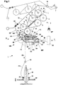
- FIG. 1 shows a schematic side view of a spinning station 1 a spinning machine (ring spinning machine) with a drafting unit 2, which is provided with an input roller pair 3, 4, a middle roller pair 5, 6 and a pair of output rollers 7, 8.
- a strap 12, 13 out which are each held around a cage, not shown in detail in its illustrated position.
- the upper rollers 4, 6, 8 of said pairs of rollers are designed as pressure rollers, which are rotatably mounted on the axes 4a, 6a, 8a on a pivotally mounted pressure arm 10.
- the pressure arm 10 is pivotally mounted about an axis 15 and, as shown schematically, acted upon by a spring element F.
- This spring element can, for. B. also be an air hose.
- the roller pairs 3, 5, 7 are driven by a drive, not shown.
- individual drives, as well as other forms of drive can be used.
- the driven lower rollers 3, 5, 7, the pressure rollers 4, 6, 8, and the belt 13 are driven via the belt 12 via friction.
- the peripheral speed of the driven roller 5 is slightly higher than the peripheral speed of the driven roller 3, so that the, the drafting unit 2 supplied fiber material in the form of a sliver L between the input roller pair 3, 4 and the middle roller pair 5, 6 subjected to a default becomes.
- the main distortion of the fiber material L takes place between the middle roller pair 5, 6 and the pair of output rollers 7, 8, wherein the output roller 7 has a substantially higher peripheral speed than the center roller 5.
- a pressure arm 10 is assigned to two adjacent drafting unit units 2 (twin drafting system). Since it is the same or partially mirror-image arranged elements of the adjacent drafting units, or compression devices, the same reference numerals are used for these parts.
- the drawn from the respective output roller pair 7, 8 stretched fiber material V is deflected downward and enters the region of a suction zone Z of a subsequent suction drum 17.
- the respective suction drum 17 is provided with extending on its circumference perforations or openings ⁇ .
- an annular suction insert 18 is arranged in each case.
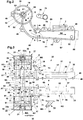
- the respective suction insert 18 is an integral part of each of a half-shell H1 and H2, wherein the two half-shells form a support member 20 in the mounted state.
- the first half-shell H1 consists of a pivot profile 55 which is open on one side and a suction insert 18 fixedly connected to it.
- the second half-shell H2 has a pivoting profile 56 which opens into a suction insert 18 connected to it.
- the suction inserts 18 are aligned transversely to the longitudinal direction of the respective half-shell H1, H2.
- the profiling of the respective half shell H1, or H2 is formed so that they can be made completely in each case in an injection mold. This makes it possible to form the air-conducting areas optimally and without sharp-edged transitions, whereby deposits of contaminants within the air-conducting areas are almost impossible.
- FIG. 3 the assembly (mounting) in the direction of the arrow of the two half-shells H1, H2 is shown to a support member 20.
- an all-round closed suction channel SK is formed ( Fig. 1 . Fig. 4 ).
- the faces SF of two half-shells H1, H2 lie on each other and are pressed against each other over several distributed over the length of the two half-shells screw 48.
- the half shells are each provided with a web 49, which each have a through hole for the screws 48.
- the end faces SF may be provided with ridges and depressions (not shown), which together form a labyrinth-shaped sealing point.
- additional sealing elements (not shown) for sealing the formed suction channel SK can be provided between the end faces SF.
- the half shells H1, H2 must be provided in this area with correspondingly shaped end faces. This will be further described in an embodiment, which in Figure 7 is shown.
- the hub G extends in the half-shell H1 between the end face SF and a radially oriented web 57 which is mounted within and in the region of the free end of the suction insert 18.
- the web 57 is provided with a central passage opening U.
- the hub G extends between the end face SF and a radially oriented web 58 which is mounted within and in the region of the free end of the suction insert 18.
- the web 58 is also provided with a central passage opening U.
- the shaft 22 In the area of the opening B and the passage openings U, the shaft 22 is mounted, which has a central part 22 m, on which on both Ends each includes an end piece 22a, which have a smaller diameter than the central part 22m.
- the inside width Lw of the opening B of the respective hub G is greater outside the existing radial bearing points than the outside diameter of the respective section 22m, 22a of the shaft 22.
- the respective hub G has a longitudinal section A1 of the opening O, at which a longitudinal section A2 adjacent whose clear width Lw is smaller than the inside width Lw of the section A1 and the diameter of the portion 22m of the shaft 22.
- a stepped recess C (shoulder) is provided in each case in which the middle section 22 m of the shaft 22 is fixed in the radial direction. That is, the inside width Lw of the recess C corresponds to the diameter of the middle part 22m of the shaft 22.
- the inner space 66 which leads as an air guide channel from the suction slots S to the suction channel SK, extends from the view N (FIG. Fig.1 ) seen from behind the shaft 22, and the hub G.
- the air sucked through the suction slots is fed directly and without further deflection to the suction channel SK, whereby the air is sucked out without disturbing swirling air.
- a further web S3 may be provided ( Fig. 2 ).
- FIG. 2 one of the half shells H1 is shown in a side view. Separately shown is a suction tube 75, which is fastened in the region of the opening 77 on the half-shell H1.
- the central axis MS of the suction tube 75 extends from its attachment point in the assembled state obliquely and at an angle c to a vertical plane E, which is parallel to a, through the central axis MA of the suction drum 17 vertical plane.
- the suction tube 75 ' which is attached to the second half-shell H2, is mirror-inverted and also extends, seen in a horizontal plane, at an angle c to the central axis MA.
- the suction tubes 75, 75 ' also seen in the horizontal direction, in addition to extend at an angle k to the central axis of the suction drums 17.
- the suction tube 75 (as well as the suction tube 75 ') on a flange 70 which is provided with a cam 78.
- the respective suction tube 75, 75 ' is fixed in its installed position in its circumferential direction.
- the respective cam 78 protrudes into a recess 79 of the respective half-shell H1, H2, which are mounted in the region of the openings 77. Due to the separate mounting of the suction tubes, it is on the one hand possible, depending on the requirements, to replace them with others. On the other hand, when creating the injection mold for the production of the half-shells H1, H2, no consideration must be given to the oblique orientation of the suction pipes, whereby the injection mold can be made simple and inexpensive.
- the respective opening 77 is sealed off by a transversely extending to the suction channel web 60 relative to the suction of the suction inserts 18 indicated by a suction air stream.
- Each of the webs 60 has ( Fig.
- the respective suction drum 17 is rotatably mounted in the region of its outer end via a bearing K on an end piece 22a of the shaft 22.
- the opposing end pieces 22a of the shaft 22 have a smaller diameter than the central part 22m of the shaft 22, so that between the middle part 22m and the adjoining end pieces 22a, a shoulder is formed with a stop surface AF.
- a locking ring 23 is mounted in a groove of the shaft, which prevents the axial displacement of the suction drum during operation.
- an opening 21 is attached, which is closed by a cap 30.
- the retaining ring 23 By removing the retaining ring 23, after removing the cap 30, it is possible to easily withdraw the respective suction drum 17 from the end piece 22a of the shaft 22 in the axial direction. As a result, a quick replacement of the suction drums 17 is possible, if necessary to exchange them with other suction drums with a different arrangement of the openings ⁇ to convert the compression element to the processing of another fiber material.
- the removal of the respective suction drum can also be done only for cleaning purposes.
- the retaining ring can also z. B. be an O-ring made of rubber or a flexible clamping ring.
- the shaft 22 is in the assembly of the two half-shells H1, H2, or provided on the half-shells suction inserts 18 according to Figure 3 in axial and in radial Location fixed.
- the shaft 22 is fixed via its middle part 22m, which has a length Lm, between the abutment surfaces T1 and T2 of the recesses C.
- the stop surfaces T1, T2 of the recesses C a distance Lx to each other, which is only slightly greater than the length Lm of the central part 22m of the shaft 22.
- the shaft is fixed in the axial direction within the suction inserts 18, wherein in each case the end pieces 22a of the shaft 22 protrude through the openings U of the webs 57, 58, on which the suction drums 17 are pushed over their bearing K.
- the shaft portion 22m rests with its outer peripheral surface on the inner peripheral surface of the recess C and is thus fixed in the radial direction.
- Fig. 4a shows a sectional view xx of the shaft 22 after Fig. 4 ,
- the shaft 22 is provided in the region of the bearings K for the respective suction drum 17 for the passage of air with a longitudinally aligned flattening 82.
- the two suction inserts 18 can be provided with additional supports 52, 53 projecting into the respective opening B, on which the middle part 22m of the shaft 22 can be supported in a specific radial direction. These supports are mounted only on a partial peripheral area of the opening and aligned according to the force effects occurring.
- the supports 52, 53 can also be formed by a corresponding shape of the cross-section of the opening B in this area.
- the two suction tubes 75, 75 ' are fixed in the region of the openings 77.
- the suction tubes 75, 75 ' have at their one end a flange 70, which is provided in the region of its peripheral surface with a radially outwardly facing cam 78.
- the outer diameter of the respective flange 70 corresponds approximately to the inner diameter of the attached to the respective half-shell H1, H2 centric to the opening 77 flange 71.
- a radially outwardly projecting recess 79 is attached, the outer contour of the contour of the Cam 78 corresponds.
- the cam 78 and the recess 79 form a positive connection, when the flange 70 of the respective suction tube 75, or 75 'is inserted into the opening of the flange 71, wherein the cam 78 and the recess 79 face each other.
- the respective suction tube is fixed in the circumferential direction and takes the desired angular position with the angle c to the respective suction drum 17 a.
- the suction tubes 75, 75 ' are held in their installed position via a slight press fit.
- other fasteners can be used to hold the mounted suction tubes in their installed position.
- a clamping roller 33 is provided for each of the suction drums 17, which rests on the respective suction drum 17 via a pressure load and forms with it a clamping line P.
- the respective pinch roller 33 is rotatably mounted on an axis 32, which is held in a guide slot 73 of a U-shaped receptacle of a pressure arm 72.
- the axis 32 is slidably mounted within the guide slot 73 transversely to its longitudinal axis.
- a plunger which rests on the outer circumference of the axis 32 and is acted upon by a pressure spring F2 shown schematically.
- the opening is approximately centrally mounted at the end of the guide slot 73 and opens into a substantially closed cavity of the pressure arm 72, in which the compression spring is arranged. This supports one end at the closed end of the cavity and rests with the opposite end on a head of the plunger.
- the pressure arm 72 is pivotally mounted about a, attached to its end axes 24 in a bearing member 80, as seen from Fig.1 can be seen schematically.
- the bearing element 80 is formed on the half-shells H1, H2 mounted webs T, and T ', which are each provided with a guide 81, via which the axes 24 of the pressure arm 72 in their, in Fig.1 shown pivot position are transferred when the two half-shells H1, H2 are interconnected.
- the axes 24 via a schematically in Fig.1 shown stop edge held transversely to its pivot axis at the end of the respective guide 81.
- pinch rollers 33 are loaded against the respective suction drum 17, wherein a nip line P is formed.
- the pressure arm is pivoted over dead center until it rests on a stop 65 which is attached to the respective half-shells H1, H2.
- the axis 32 of the pinch rollers 33 is below the plane passing through the pivot axis 24 and the center axis MA of the suction drums 17. That is, the pinch roller 33 is held over dead center in this position. Further details with respect to the attachment and execution of the pinch rollers 33 can also be found in the CH705308 be removed.
- the compacting device VM is now pre-assembled and is now attached to the respective drafting system 2 (twin drafting) on the spinning machine.
- the support member 20 is inserted with the attached to the pivot profiles 55, 56 of the half shells H1, H2 axes 32 in receptacles 34 on the machine frame MR and not shown clamping elements or other means in this in Fig.1 shown pivot position held.
- the compaction device Pivot VM via the pivot axes 32 in a lower position until it rests on a, attached to the machine frame MR stop 64 and held there.
- the compacting device VM is pivoted about the axes 32 in an upper position until the mounted on the respective suction drum 17 friction rings 28 (friction wheel) rest on the respective driven roller 7 of the pair of drafting rollers 2.
- the pressure lever 10 about its pivot axis 15 of a dashed upper position ( Fig.1 ) is pivoted to a lower position, in which a pressure force is exerted on the support element 20 of the compacting device VM in the direction of the roller 7 via a leaf spring 68 fastened by means of screws to the pressure lever 10 and the web 62 secured to the leaf spring.
- a pressure force is exerted on the support element 20 of the compacting device VM in the direction of the roller 7 via a leaf spring 68 fastened by means of screws to the pressure lever 10 and the web 62 secured to the leaf spring.
- the respective friction ring 28 and thus the associated suction drum 17 is driven by the roller 7 via friction.
- the friction ring 28 may be made of an elastic material, such. B. made of rubber.
- a vacuum source SP is provided which communicates with a central suction channel 85.
- the suction channel 85 is connected via a line 86, a flexible coupling element 88 with the respective, in the direction of the suction channel 85 projecting end of the suction channel SK of the compression device VM, in conjunction. Due to the flexibility of the coupling element 88, the pivotability of the compacting device about the axis 32 is made possible.
- the coupling element 88 shown schematically may be formed on its outer circumference, so that it is positively connected to the formed suction channel SK when joining the two half-shells H1, H2 and to the outside.
- the nip line P generated by the pinch roller 33 simultaneously forms a so-called “rotation locking gap", from which the fiber material in the conveying direction FS in the form of a compressed yarn FK is supplied under rotation distribution of a ring spinning device shown schematically.
- This is provided with a ring 39 and a rotor 40, wherein the yarn is wound on a sleeve 41 to form a coil 42 (Kops).
- a yarn guide 43 is arranged between the nip line P and the rotor 40.
- the ring 39 is attached to a ring frame 44, which performs an up and down movement during the spinning process.
- the yarn FK further supplied via the nip P is conveyed via the respective suction pipe 75 and 75 'via the opening 77 under the action of the exhaust pipe 75 mounted on the support member 20 via the negative pressure source SP Vacuum sucked through the suction channel SK and the suction channel 85 is supplied.
- the respective suction opening 38 of the suction tubes 75, or 75 ' is assigned to the side of the yarn course.
- a recess X is in each case mounted on the peripheral surface of the respective suction insert 18.
- a step-shaped shoulder 90 in the region of the end faces 84 of the suction drums 17, which prevents 20 accumulated fiber fly in the center region of the support member 20 can move into the gap 87 between the suction drum 17 and the suction insert 18.
- the respective step-shaped step 90 provides a barrier to lateral displacement of deposits. Such deposits are then removed in time over cleaning intervals before they can overcome the described barrier.
- FIG Figure 5 View H
- FIG Figure 7 Another embodiment with respect to the connection of the two half-shells H1, H2 is shown in FIG Figure 5 (View H) shown, which as an enlarged partial view in Figure 7 is shown in more detail.
- the two half shells H1, H2 at their ends encircling flanges 45, 46, via which the two half-shells with each other without additional additives (eg., Pins, screws or the like) positively connected become.
- additional additives eg., Pins, screws or the like
- the flange 45 of the first half-shell H2 is provided with an inwardly pointing shoulder 92, whose inner surface 93 engages over the outer surface 94 of the half-shell H1 partially and comes to rest thereon in the mounted position. Furthermore, a flange 46 is attached to the half-shell H1, which completely overlaps or covers the flange 45 on its outer surface AL.
- the flange 46 has an L-shaped cross-sectional area which forms an inwardly directed receptacle 50 over which the flange 46 forms a positive connection with the flange 45 in the illustrated assembled position.
- the term "inside” refers to the interior of the mounted half-shells H1, H2.
- the flange 46 At the end of the L-shaped cross-section of the flange 46 is provided with an inwardly projecting web 89 which projects beyond the rear surface 91 of the flange 45 and holds the flange 45 in its shown locking position in the receptacle 50 of the flange 46. D. h., When the connection is to be released again, force is necessary to deflect the L-shaped portion of the flange 46 on the existing elasticity outwards until the web 89 is outside the surface 91 and thus the outlet of the flange 45 allows the recording 50. To facilitate assembly of the flange 46 is provided with a chamfer 95.
- a gap 36 with the distance n between the surfaces 45a and 46a of the flanges 45, 46 is provided. This prevents fibers from being trapped in this area.
- the gap 36 is sealed off from the ambient air by the inner surface 93 of the flange 45 to the outside.
Landscapes
- Engineering & Computer Science (AREA)
- Mechanical Engineering (AREA)
- Textile Engineering (AREA)
- Spinning Or Twisting Of Yarns (AREA)
Description
Die Erfindung bezieht sich auf ein Tragelement für eine Verdichtungsvorrichtung für zwei nebeneinander angeordneten Streckwerkseinheiten einer Spinnmaschine nach dem Oberbegriff des Patentanspruches 1.The invention relates to a support element for a compression device for two juxtaposed drafting units of a spinning machine according to the preamble of
Aus der Praxis sind bereits eine Vielzahl von Ausführungen bekannt, wobei zum Kompaktieren (Verdichten) des von einer Streckwerkseinheit abgegebenen Fasergutes (Faserstrang) eine Verdichtungseinrichtung nachgeordnet ist. Im Anschluss an eine solche Verdichtungseinrichtung wird das verdichtete Fasergut, nach Passieren einer Klemmstelle, einer Drallerzeugungsvorrichtung zugeführt. Eine solche Drallerzeugungsvorrichtung besteht z. B. bei einer Ringspinnmaschine aus einem Läufer, der auf einem Ring umläuft, wobei das erzeugte Garn auf eine rotierende Hülse aufgewickelt wird. Als Verdichtungseinrichtungen kommen im wesentlichen besaugte umlaufende, perforierte Saugtrommeln oder umlaufende, mit Perforationen versehene Riemchen zum Einsatz. Dabei wird unter Verwendung von entsprechenden Einsätzen innerhalb der Saugtrommel, bzw. innerhalb der umlaufenden Riemchen ein spezieller Saugbereich auf dem Verdichtungselement definiert. Derartige Einsätze können dabei z. B. mit entsprechend geformten Saugschlitzen versehen werden, an welche ein Unterdruck angelegt wird, wodurch eine entsprechende Luftströmung an der Peripherie des jeweiligen Verdichtungselementes erzeugt wird. Durch diese Luftströmung, welche im wesentlichen quer zur Transportrichtung des Fasergutes ausgerichtet ist, werden insbesondere abstehende Fasern in das Garn mit eingebunden.From practice, a variety of designs are already known, for compacting (compacting) of the votes of a drafting unit fiber material (fiber strand) downstream of a compacting device. Subsequent to such a compacting device, the compacted fiber material, after passing through a nip, a swirl-generating device is supplied. Such a swirl generating device consists for. Example, in a ring spinning machine from a rotor which rotates on a ring, wherein the yarn produced is wound on a rotating sleeve. As compression means are substantially evacuated circumferential, perforated suction drums or circumferential, provided with perforations straps used. In this case, a special suction region is defined on the compression element using corresponding inserts within the suction drum, or within the circumferential straps. Such inserts can be z. B. are provided with correspondingly shaped suction slots, to which a negative pressure is applied, whereby a corresponding air flow is generated at the periphery of the respective compression element. By this air flow, which is aligned substantially transversely to the transport direction of the fiber material, in particular projecting fibers are involved in the yarn.
Bei den bekannten Lösungen wird das von der Streckwerkseinheit abgegebene Fasergut oberhalb oder auch unterhalb der verwendeten Verdichtungsvorrichtungen geführt. Insbesondere beim Einsatz an einer Ringspinnmaschine ist es erforderlich, im Anschluss an die Saugzone eine zusätzliche Klemmstelle vorzusehen, um eine Drallsperrung zu erhalten.In the known solutions, the fiber material discharged by the drafting unit is guided above or else below the compacting devices used. In particular, when used on a ring spinning machine, it is necessary to provide an additional nip following the suction zone in order to obtain a twist lock.
Derartige solche Einrichtungen sind z. B. in den Veröffentlichungen
In der Praxis besteht die Forderung vorhandene Spinnmaschinen mit einer herkömmlichen Streckwerkseinheit mit einer solchen Verdichtungsvorrichtung nach zurüsten, um sich auch bei diesen Maschinen die Möglichkeit der Herstellung von qualitativ hochwertigen Garnen zu sichern. Es wurden deshalb Vorrichtungen vorgeschlagen, mit welchen herkömmliche Streckwerke mit einer solchen Verdichtungsvorrichtung nachgerüstet werden können. Eine solche ist z. B. aus der
Aus
Aus der
Aus der
Bei den zuvor beschriebenen Ausführungen werden die Saugelemente, welche einem definierten Verdichtungsbereich zum Komprimieren des Fasergutes zugeordnet sind, über zusätzlich angeordnete Leitungen, die mit einer Unterdruckquelle verbunden sind, mit einem Unterdruck beaufschlagt.In the embodiments described above, the suction elements, which are associated with a defined compression area for compressing the fiber material, are acted upon by additionally arranged lines, which are connected to a vacuum source, with a negative pressure.
Zur Vereinfachung derartiger Verdichtungsvorrichtungen, wobei eine einfache und schnelle Installation an konventionelle Streckwerkseinheiten ermöglicht wird, ohne dass zusätzliche Antriebselemente installiert werden müssen, wird in der
Das Tragelement ist im vorliegenden Beispiel zur drehbeweglichen Lagerung von zwei koaxial und nebeneinander angeordneten Saugtrommeln vorgesehen, welche im Anschluss an zwei benachbarten Streckwerkseinheiten, einem so genannten Zwillingsstreckwerk, angebracht sind. Unter einem Zwillingsstreckwerk sind zwei benachbarte Streckwerkseinheiten zu verstehen, deren Druckwalzen über einen gemeinsamen Druckarm belastet werden.The support member is provided in the present example for the rotatable mounting of two coaxial and juxtaposed suction drums, which are attached to two adjacent drafting units, a so-called twin drafting. Under a twin drafting two adjacent drafting units are to be understood, the pressure rollers are loaded via a common pressure arm.
Innerhalb des Tragelementes (Träger) ist ein Saugkanal für das Anlegen eines Unterdruckes an die Verdichtungselemente vorgesehen. Dabei steht ein erstes Ende des Saugkanals mit dem jeweiligen Verdichtungselement in Verbindung und sein zweites Ende endet im Bereich des Tragelementes, mit welchem das Tragelement in seiner montierten Position an der Spinnmaschine befestigt ist. Das zweite Ende des Saugkanals innerhalb des Tragelementes bildet eine Kupplungsstelle für den Anschluss eines weiteren Luftkanals, der mit einem Hauptkanal in Verbindung steht.Within the support element (carrier), a suction channel for applying a negative pressure to the compression elements is provided. In this case, a first end of the suction channel communicates with the respective compression element and its second end terminates in the region of the support element with which the support element is fastened in its mounted position on the spinning machine. The second end of the suction channel within the support element forms a coupling point for the connection of a further air channel, which is in communication with a main channel.
D. h. bei der vorgeschlagenen Ausführung dient das Tragelement (Träger) einerseits als Aufnahme und Lagerelement für die Verdichtungselemente (z. B. drehbar gelagerte Saugtrommeln mit fest installierten Saugeinsätzen) und andererseits als Kanal zum Anlegen eines Luftunterdruckes an die entsprechenden Saugeinsätze der Verdichtungseinheiten.Ie. in the proposed embodiment, the support element (support) serves on the one hand as a receptacle and bearing element for the compression elements (eg rotatably mounted suction drums with permanently installed suction inserts) and on the other hand as a channel for applying a negative air pressure to the corresponding suction inserts of the compression units.
Der Erfindung liegt nunmehr die Aufgabe zu Grunde, das in der
Diese Aufgabe wird bei einem Tragelement entsprechend dem Oberbegriff des unabhängigen Anspruchs durch die kennzeichnenden Merkmale gelöst.This object is achieved in a support element according to the preamble of the independent claim by the characterizing features.
Der Begriff "nach aussen hin ragender Saugeinsatz" bedeutet, dass sich der Saugeinsatz der jeweiligen Halbschale quer zur Längsrichtung und weg vom Saugkanal der Halbschale, bzw. des Förderkanals erstreckt.The term "outwardly projecting suction insert" means that the suction insert of the respective half-shell extends transversely to the longitudinal direction and away from the suction channel of the half-shell, or of the conveying channel.
Des Weiteren wird vorgeschlagen, dass die Welle mit zwei Endabschnitten versehen ist, welche gegenüber einem Mittenbereich der Welle einen kleineren Durchmesser aufweisen und die Durchtrittsöffnung des Lagerelementes des jeweiligen Saugeinsatzes mit einer stufenförmigen Verringerung ihrer lichten Weite versehen ist, wobei die, mit der grösseren lichten Weite versehenen Abschnitte der Durchtrittsöffnungen koaxial aneinander angrenzen und der, mit einem grösseren Durchmesser als die verringerte lichte Weite der Durchtrittsöffnung versehene Mittelabschnitt der Welle innerhalb der genannten, aneinander grenzenden Abschnitte zwischen Anschlagflächen der jeweiligen stufenförmigen Verringerung der Durchtrittsöffnungen in axialer Richtung fixiert wird.Furthermore, it is proposed that the shaft is provided with two end portions, which have a smaller diameter relative to a central region of the shaft and the passage opening of the bearing element of the respective suction insert is provided with a stepped reduction in their inside diameter, wherein the, with the larger clear width provided portions of the passage openings adjoin one another coaxially and the, provided with a larger diameter than the reduced inside diameter of the passage opening central portion of the shaft within said, adjacent sections between abutment surfaces of the respective stepped reduction of the passage openings in the axial direction is fixed.
Durch den Vorschlag, das Tragelement aus zwei, miteinander verbindbaren Halbschalen auszubilden, wird dessen Herstellung vereinfacht wobei ermöglicht wird, dass die Halbschalen als einfache Spritzgussteile hergestellt werden können. Gleichzeitig kann dabei, der, mit der jeweiligen Halbschale verbundene, rohrförmige Saugeinsatz im gleichen Arbeitsvorgang gefertigt werden. Im montierten Zustand der beiden Halbschalen sind die, an den Halbschalen angebrachten Saugeinsätze koaxial zueinander ausgerichtet. Durch die entsprechende Anbringung einer Durchtrittsöffnung im Zentrum einer, die Welle in radialer Richtung lagernden Aufnahme des jeweiligen Saugeinsatzes, wird die Welle, die zur drehbaren Lagerung der Saugtrommeln vorgesehen ist, beim Zusammenfügen der beiden Halbschalen gleichzeitig auch in axialer Richtung fixiert. Damit bilden die jeweilige Halbschale des Tragelementes und der ihr zugeordnete Saugeinsatz eine einstückige, stabile Einheit.By proposing to form the support element of two half-shells which can be connected to one another, its manufacture is simplified, whereby it is made possible for the half-shells to be produced as simple injection-molded parts. At the same time, the, connected to the respective half-shell, tubular suction insert can be made in the same operation. In the assembled state of the two half-shells attached to the half-shells suction inserts are aligned coaxially with each other. By the appropriate attachment of a passage opening in the center of a, the shaft in the radial direction superimposed recording of the respective suction insert, the shaft which is provided for rotatably supporting the suction drums, at the same time fixed in the axial direction when joining the two half-shells. In order to The respective half shell of the support element and its associated suction insert form a one-piece, stable unit.
Durch die entsprechend vorgeschlagene, zu ihren Enden hin, im Durchmesser abgesetzte Ausführung der Welle, kann diese mit ihren Enden durch die Durchtrittsöffnungen des Lagerelementes der Saugeinsätze hindurchragen und wird über ihren, im Durchmesser vergrösserten Mittelteil beim Zusammenfügen der beiden Halbschalen zwischen den, sich gegenüber stehenden Seiten der stufenförmigen Durchmesserverringerung der Durchtrittsöffnungen in ihrer axialen Richtung fixiert. Dies wird gewährleistet, indem der Durchmesser der verringerten Durchtrittsöffnungen kleiner ist als der Durchmesser des Mittelteiles der Welle. Es ist auch denkbar, dass die Lagerelemente zur radialen Fixierung der Welle im Bereich der stufenförmigen Durchmesserverringerung mit koaxial zu der jeweiligen Durchtrittsöffnung angebrachten Vertiefungen versehen sind, wobei die Grundfläche der jeweiligen Vertiefung als Anschlagfläche für die axiale Fixierung des Mittelteiles der Welle dient und in Umfangsrichtung der Vertiefung den Mittelteil der Welle in radialer Richtung fixiert. D.h., der Durchmesser des Mittelteiles der Welle entspricht der lichten Weite der Vertiefung und wird in dieser über eine Spielpassung in radialer Richtung gehalten.By appropriately proposed, towards their ends, stepped in diameter design of the shaft, this can protrude with their ends through the openings of the bearing element of the suction inserts and is about their, enlarged in diameter middle part when joining the two half-shells between the opposite Fixed sides of the stepped diameter reduction of the passage openings in its axial direction. This is ensured by the diameter of the reduced passage openings is smaller than the diameter of the central part of the shaft. It is also conceivable that the bearing elements are provided for radially fixing the shaft in the region of the stepped diameter reduction with coaxial with the respective passage opening recesses, the base of the respective recess serves as a stop surface for the axial fixation of the central part of the shaft and in the circumferential direction of the Deepening the middle part of the shaft fixed in the radial direction. That is, the diameter of the central portion of the shaft corresponds to the clear width of the recess and is held in this via a clearance in the radial direction.
Durch die vorgeschlagene Ausführung des Tragelementes wird ein einfaches Herstellungsverfahren ermöglicht und gleichzeitig die Montage der mit dem Tragelement verbundenen Elemente (z. B. die Welle für die Saugtrommeln) vereinfacht.The proposed design of the support element enables a simple manufacturing process and at the same time simplifies the assembly of the elements connected to the support element (eg the shaft for the suction drums).
Des Weiteren wird vorgeschlagen, dass die beiden Halbschalen jeweils mit einer Öffnung für die Aufnahme jeweils eines Absaugrohres versehen sind, welche der jeweiligen Saugtrommel zugeordnet sind, wobei die Mittelachsen der Öffnungen im montierten Zustand des Tragelementes koaxial zueinander ausgerichtet sind und deren koaxiale gemeinsame Achse in einem parallelen Abstand zu der Achse der die Saugtrommeln lagernde Welle verlaufen. Die Öffnungen münden dabei jeweils im Randbereich des Saugkanals.Furthermore, it is proposed that the two half-shells are each provided with an opening for receiving a respective suction tube, which are associated with the respective suction drum, wherein the center axes of the openings in the mounted state of the support element are aligned coaxially with each other and their coaxial common axis in one parallel distance to the axis of the suction drums superimposed shaft. The openings open in each case in the edge region of the suction channel.
Durch die vorgeschlagene Anbringung der koaxial gegenüberliegenden Öffnungen für die Absaugrohre im Randbereich des Saugkanals wird die Luftströmung, welche durch den an den Saugeinsätzen angelegten Unterdruck entsteht, nicht negativ gestört, bzw. beeinflusst. Die, durch den angelegten Unterdruck über die Absaugrohre in Richtung der Kanalmitte entstehenden Luftströmungen prallen im Mittenbereich des Saugkanals aufeinander und werden dann in Richtung des Saugluftstromes innerhalb des Saugkanals umgelenkt. Damit sind keine festen Umlenkkanten für die, über die Absaugrohre angesaugte Luftströmung vorhanden, wodurch keine Reibungsverluste in der Luftführung in diesem Bereich entstehen können.Due to the proposed attachment of the coaxial openings for the suction tubes in the edge region of the suction channel, the air flow through which The applied to the suction inserts negative pressure, not negatively disturbed, or influenced. The, caused by the applied negative pressure on the suction tubes in the direction of the channel center air currents collide in the central region of the suction channel to each other and are then redirected in the direction of the suction air flow within the suction channel. This means that there are no fixed deflecting edges for the air flow sucked in via the suction pipes, as a result of which no friction losses in the air duct can arise in this area.
Vorteilhafterweise wird weiter vorgeschlagen, dass im Bereich der Öffnungen für die Absaugrohre die jeweilige Halbschale mit zur Mitte des Saugkanals ragenden Stegen versehen ist, welche axial und in Verlängerung zur jeweiligen Öffnung auf der Seite der Öffnung verlaufen, welche den Saugtrommeln zugekehrt ist.Advantageously, it is further proposed that in the region of the openings for the suction pipes, the respective half-shell is provided with projecting to the center of the suction channel webs which extend axially and in extension to the respective opening on the side of the opening which faces the suction drums.
Damit wird der von den Absaugrohren in den Saugkanal strömende Luftstrom zum grössten Teil gegenüber dem, von den Saugeinsätzen kommenden Saugluftstrom abgeschottet. D. h. eine Zusammenführung beider Saugluftströmungen erfolgt erst in dem Bereich, in welchem der von den Saugeinsätzen kommende erste Saugluftstrom die zur Mitte des Saugkanals ragende Stege bereits passiert hat und in welchem der von den Absaugrohren kommende zweite Saugluftstrom bereits in Richtung des ersten Saugluftstromes umgelenkt wurde. Damit werden unkontrollierte Luftverwirbelungen innerhalb des Saugkanals vermieden und somit auch das Ansammeln von Verschmutzungen und Fasermaterial in diesem Bereich.Thus, the air flow flowing from the suction tubes into the suction channel is mostly sealed off from the suction air flow coming from the suction inserts. Ie. a combination of the two Saugluftströmungen takes place only in the area in which coming from the suction first suction air stream has already passed to the middle of the suction channel webs and in which coming from the suction second suction air stream has already been redirected in the direction of the first suction air stream. This avoids uncontrolled air turbulence within the suction channel and thus also the accumulation of dirt and fiber material in this area.
Damit beim Zusammenfügen der beiden Halbschalen zwischen den aneinander grenzenden Stegen keine Stelle entsteht, an welcher sich einzelne Fasern festklemmen können, wird vorgeschlagen zwischen den aneinander grenzenden Flächen der Stege einen Abstand vorzusehen, welcher so gross sein muss, so dass ein Festklemmen von Fasern an dieser Stelle verhindert wird. D. h., werden Fasern durch den Saugluftstrom in diesen Bereich überführt, so können sie durch den vorhandenen Schlitz hindurch treten, ohne festzuklemmen.So that when joining the two half shells between the adjacent webs no place arises at which individual fibers can clamp, it is proposed to provide a distance between the adjacent surfaces of the webs, which must be so large, so that a clamping of fibers to this Job is prevented. That is, when fibers are transferred to the area by the suction air flow, they can pass through the existing slot without jamming.
Vorteilhafterweise werden die Absaugrohre demontierbar an der jeweiligen Öffnung angebracht. Dadurch ist es möglich unterschiedliche Absaugrohre je nach Bedarf gegeneinander auszutauschen. Gleichzeitig kann die Herstellung der beiden Halbschalen des Tragelementes ohne Berücksichtigung komplizierter Spritzgussformen erfolgen, die notwendig sind, wenn die Absaugrohre fest mit den Halbschalen verbunden wären. Dadurch kann, wie weiter beansprucht, und ohne Beeinträchtigung der Herstellung der beiden Halbschalen, die Mittelachse des jeweiligen Absaugrohres unter einem Winkel zur Achse der, die Saugtrommel tragende Welle verlaufen. Damit vergrössert sich, ausgehend von der äusseren Saugöffnung des Absaugrohres in Richtung der Öffnung der Halbschale, der Abstand zwischen dem jeweiligen Absaugrohr und der, dem Absaugrohr gegenüberliegenden Saugtrommel. Damit kann der Freiraum zwischen den jeweiligen Absaugrohren und der jeweiligen Saugtrommel so gross gehalten werden, so dass sich in diesem Bereich keine Ablagerungen durch Faserflug bilden können.Advantageously, the suction pipes are removably attached to the respective opening. This makes it possible different suction tubes as needed against each other exchange. At the same time, the production of the two half-shells of the support element can take place without consideration of complicated injection molds, which are necessary if the suction tubes were firmly connected to the half-shells. Thereby, as further claimed, and without affecting the production of the two half-shells, the central axis of the respective suction pipe at an angle to the axis of the suction drum supporting shaft. This increases, starting from the outer suction opening of the suction tube in the direction of the opening of the half-shell, the distance between the respective suction tube and, the suction tube opposite suction drum. Thus, the space between the respective suction pipes and the respective suction drum can be kept so large, so that no deposits can form in this area by fiber fly.
Um die Absaugrohre in Bezug auf schräge Anordnung exakt auf den vorgesehenen Absaugbereich der jeweiligen Saugtrommel auszurichten wird vorgeschlagen, dass die Absaugrohre mit Erhöhungen und/oder Vertiefungen versehen sind über welche sie in Umfangsrichtung mit Erhöhungen und/oder Vertiefungen im Bereich der Öffnung der Halbschale einen Formschluss bilden.In order to align the suction tubes with respect to an oblique arrangement exactly on the intended suction of the respective suction drum, it is proposed that the suction tubes are provided with elevations and / or depressions via which they form a positive connection in the circumferential direction with elevations and / or depressions in the region of the opening of the half-shell form.
Des Weiteren wird vorgeschlagen, dass die äussere Saugöffnungen der Absaugrohre in Ebenen liegen, welche in horizontaler Richtung und in Absaugrichtung des Faserkanals gesehen einen spitzen Winkel bilden und sich in vertikaler Richtung gesehen, oberhalb des Saugkanals aufeinander zu bewegen.Furthermore, it is proposed that the outer suction openings of the suction tubes lie in planes which, viewed in the horizontal direction and in the suction direction of the fiber channel, form an acute angle and move toward one another above the suction channel in the vertical direction.
Mit dieser vorgeschlagenen, im Raum schräg ausgerichteten Saugöffnungen wird in Bezug auf den Fadenverlauf eine optimale Absaugwirkung erzielt, womit ein gebrochenes Fadenende schnell erfasst und dem Absaugkanal zugeführt werden kann. Vorzugsweise könnte sich die Absaugöffnung auch noch teilweise hinter dem Fadenverlauf befinden (gesehen in Vorderansicht der Verdichtungsvorrichtung).With this proposed, in the space obliquely oriented suction openings an optimal suction effect is achieved with respect to the thread path, whereby a broken thread end can be quickly detected and fed to the suction channel. Preferably, the suction opening could also be partially behind the yarn course (as seen in front view of the compacting device).
Des Weiteren wird vorgeschlagen, dass die Lagerelemente der beiden Saugeinsätze der Halbschalen jeweils eine zusätzliche radiale Abstützung für die Welle aufweisen, welche benachbart in dem Bereich vorgesehen ist, in welchem die Halbschalen in montierter Stellung aneinander liegen.Furthermore, it is proposed that the bearing elements of the two suction inserts of the half shells each have an additional radial support for the shaft, which is provided adjacent in the region in which the half shells lie in the mounted position to each other.
Durch die zusätzliche mittige radiale Abstützung der Welle über zusätzliche Stützelemente im Lagerelement, wird ein Auseinandertriften der beiden Halbschalen verhindert, welches infolge der, auf die Saugtrommeln wirkenden radialen Druckkräfte entstehen könnte.The additional central radial support of the shaft via additional support elements in the bearing element, a separation of the two half shells is prevented, which could arise as a result of acting on the suction drums radial compressive forces.
Um ein Verdrehen der Welle im Lagerelement zu verhindern, wird weiter vorgeschlagen, dass wenigstens eine der radialen Abstützungen in den Halbschalen mit der Welle eine, in Umfangsrichtung der Welle gesehen, formschlüssige Verbindung bildet. Damit wird gewährleistet, dass sich lediglich die über Lager auf der Welle gelagerten Saugtrommeln drehen und die Welle stillsteht und somit kein Verschleiss zwischen der Welle und ihrer radialen Abstützungen im Lagerelement entsteht.In order to prevent rotation of the shaft in the bearing element, it is further proposed that at least one of the radial supports forms a positive connection in the half shells with the shaft, seen in the circumferential direction of the shaft. This ensures that only the suction drums mounted on the shaft via bearings rotate and the shaft stops and thus no wear occurs between the shaft and its radial supports in the bearing element.
Damit der durch eine Saugquelle erzeugte Saugluftstrom im Bereich der Lagerung der Saugtrommeln nicht durch die, mit Fett versehenen Lager durchströmt, wird vorgeschlagen, dass die Welle im Bereich der Lagerstellen für die jeweilige Saugtrommel für den Luftdurchtritt mit einer in Längsrichtung ausgerichteter Abflachung versehen ist. Dadurch kann der Saugluftstrom im Bereich der Abflachung der Welle an den, mit Fett geschmierten Lagern vorbei geleitet werden. Ohne einen solchen, durch die vorgeschlagene Abflachung entstandenen Bypass kann es vorkommen, dass das Fett durch die Saugluftströmung aus den Lagern herausgepresst wird, welches sich dass auf Teile der Welle oder der Halbschalen absetzen kann. Dadurch können sich im Saugluftstrom befindliche Fasern in den Bereichen, wo das Fett anhaftet festgehalten werden, was zu Verstopfungen führen kann.So that the suction air flow generated by a suction source in the region of the bearing of the suction drums does not flow through the provided with grease bearing, it is proposed that the shaft is provided in the region of the bearing points for the respective suction drum for the passage of air with a longitudinally aligned flattening. This allows the suction air flow in the area of the flattening of the shaft to be routed past the grease-lubricated bearings. Without such a bypass created by the proposed flattening, it may happen that the grease is forced out of the bearings by the suction air flow, which may settle on parts of the shaft or half shells. As a result, located in the suction air flow fibers can be held in the areas where the fat adheres, which can lead to blockages.
Zu einfachen visueller Überwachung des Tragelementes mit den daran befestigten Saugeinsätzen wird vorgeschlagen, dass die Halbschalen aus einem durchsichtigen Kunststoffmaterial hergestellt sind.For easy visual monitoring of the support element with the attached suction inserts is proposed that the half shells are made of a transparent plastic material.
Weiterhin wird eine Ausführung vorgeschlagen, wobei der jeweilige Saugeinsatz der Halbschalen mit einer, auf dem Aussenumfang des Saugeinsatzes verlaufender Vertiefung versehen ist, welche im Bereich zwischen der Stirnfläche der jeweiligen Halbschale, mit welchen sie aneinander liegen und der jeweiligen, den Saugeinsatz überragenden Stirnfläche der Saugtrommel angeordnet ist.Furthermore, an embodiment is proposed, wherein the respective suction insert of the half-shells is provided with a, running on the outer circumference of the suction insert recess which in the region between the end face of the respective half-shell, with which they lie against each other and the respective, the suction insert superior face of the suction drum is arranged.
Damit soll verhindert werden, dass sich eventuell im Mittenbereich des Tragelementes festsetzender Faserflug und sonstige Verschmutzungen in den radialen Ringspalt zwischen der jeweiligen Saugtrommel und dem Saugeinsatz gelangen kann. D. h. durch die vorgesehene Vertiefung setzt sich der Faserflug in dieser Vertiefung ab und wird durch die seitliche Begrenzung der Vertiefung daran gehindert sich in axialer Richtung zu der jeweiligen Saugtrommel in den beschriebenen Ringspalt zu verschieben. Durch in regelmässigen Abständen durchgeführte Reinigungszyklen, bei welchen die Aggregate durch entsprechend Vorrichtungen manuell oder automatisch mit Druckluft gereinigt werden, werden diese Ablagerungen entfernt, bevor sie den jeweiligen Ringspalt gelangen können.This is to prevent that may possibly get stuck in the middle region of the support element festsetzender fiber fly and other contaminants in the radial annular gap between the respective suction drum and the suction insert. Ie. through the intended depression, the fiber fly settles in this depression and is prevented by the lateral boundary of the depression from moving in the axial direction to the respective suction drum in the described annular gap. By regularly performed cleaning cycles, in which the units are cleaned by appropriate devices manually or automatically with compressed air, these deposits are removed before they can reach the respective annular gap.
Vorteilhafterweise können im Bereich der Flächen, mit welchen die beiden Halbschalen beim Zusammenfügen (Montage) aufeinander anliegen, Lamellenförmige Abstufungen (Feder / Nut -Prinzip) vorgesehen sein, um den durch die beiden Halbschalen gebildeten Saugkanal gegenüber der Umgebungsluft abzuschotten. Sofern notwendig, können auch noch umlaufende Dichtungselemente eingesetzt werden.Advantageously, in the area of the surfaces with which the two half-shells abut each other during assembly (assembly), lamellar gradations (spring / groove principle) may be provided in order to seal off the suction channel formed by the two half-shells from the ambient air. If necessary, even circumferential sealing elements can be used.
Anstelle einer Schraubverbindung zwischen den beiden Halbschalen können diese auch über eine Kleb- oder Schweissverbindung miteinander verbunden werden. Es sind auch Schnappverbindungen mit labyrinthartigen Dichtelementen denkbar, die den Saugkanal gegenüber der Umgebung abschotten.Instead of a screw connection between the two half-shells, these can also be connected to one another via an adhesive or welding connection. There are also snap connections with labyrinth-like sealing elements conceivable that seal the suction against the environment.
Beim Zusammenfügen der beiden Halbschalen werden auch die jeweiligen Saugeinsätze gegeneinander gepresst, wodurch sich ein Innenraum innerhalb der Saugeinsätze bildet, welcher einerseits mit dem Saugkanal und andererseits mit dem jeweiligen Saugschlitz in Verbindung steht. Zur Begrenzung dieses Innenraumes (Luftführender Kanal) können in Längsrichtung des jeweiligen Saugeinsatzes verlaufende und radial nach aussen gerichtete Stege vorgesehen sein. Diese sind in Vorteilhafterweise so angeordnet, so dass der Innenraum, der als Luftführungskanal von den Saugschlitzen zum Saugkanal führt, von der Vorderansicht aus gesehen, hinter der Welle verläuft.When joining the two half-shells and the respective suction inserts are pressed against each other, whereby an interior forms within the suction inserts, which is on the one hand with the suction channel and on the other hand with the respective suction slot in connection. To limit this interior space (air-conducting channel) extending in the longitudinal direction of the respective suction insert and radially outwardly directed webs may be provided. These are advantageously arranged so that the interior, which leads as an air duct from the suction slots to the suction channel, seen from the front view, behind the shaft.
Dadurch wird die durch die Saugschlitze angesaugte Luft direkt und ohne weitere Umlenkung dem Saugkanal zugeführt, womit die Luft ohne störende Luftwirbel abgesaugt werden kann.As a result, the sucked through the suction slots air is fed directly to the suction channel without further deflection, so that the air can be sucked without disturbing air vortex.
Des Weiteren wird eine Ausführungsform für die Verbindung der beiden Halbschalen vorgeschlagen, wobei die beiden Halbschalen mit jeweils einem umlaufenden Flansch versehen sind, wobei - in montierter Stellung der beiden Halbschalen gesehen - der Flansch der zweiten Halbschale die erste Halbschale teilweise überragt und der Flansch der ersten Halbschale den Flansch der zweiten Halbschale vollständig überragt und mit diesem eine formschlüssige Klemmverbindung bildet. Dadurch erhält man eine Verbindung ohne Einsatz zusätzlicher Verbindungsmittel (z. B. Schrauben, Nieten usw.) wobei gleichzeitig eine Abdichtung des Innenraumes gegenüber der Umgebung erzielt wird.Furthermore, an embodiment for the connection of the two half shells is proposed, wherein the two half shells are each provided with a circumferential flange, wherein - viewed in the mounted position of the two half shells - the flange of the second half shell partially surmounted the first half shell and the flange of the first Half shell completely surmounted the flange of the second half-shell and forms a positive clamping connection with this. This provides a connection without the use of additional connecting means (eg screws, rivets, etc.) while at the same time sealing the interior from the environment.
Vorteilhafterweise wird weiter vorgeschlagen, dass der Flansch der zweiten Halbschale mit einer nach innen gerichteten offenen Aufnahme versehen ist, in welcher formschlüssig die Aussenkontur des Flansches der ersten Halbschale aufgenommen ist und der Flansch der zweiten Halbschale im Bereich der freien Überragung des Flansches der ersten Halbschale mit einem nach innen gerichteten Steg versehen ist, der den Flansch der ersten Halbschale teilweise überragt.Advantageously, it is further proposed that the flange of the second half-shell is provided with an inwardly directed receptacle in which positively engages the outer contour of the flange of the first half-shell and the flange of the second half-shell in the region of the free transfer of the flange of the first half-shell an inwardly directed web is provided, which projects beyond the flange of the first half-shell partially.
Des Weiteren wird vorgeschlagen, dass in montierter Stellung der beiden Halbschalen zwischen den Stirnflächen der Flansche der Halbschalen ein, in Richtung des Innenraumes der beiden Halbschalen hin offener Spalt vorgesehen ist, der nach aussen hin durch den Flansch der ersten Halbschale abgeschottet wird.Furthermore, it is proposed that in the mounted position of the two half-shells between the end faces of the flanges of the half-shells, a gap is provided in the direction of the interior of the two half shells, which is sealed off to the outside by the flange of the first half-shell.
Weitere Vorteile der Erfindung werden anhand nachfolgenden Ausführungsbeispielen näher aufgezeigt und beschrieben.Further advantages of the invention will be shown and described in more detail with reference to subsequent embodiments.
Es zeigen:
- Fig. 1
- eine schematische Seitenansicht einer, an einem Tragelement angebrachten Verdichtungsvorrichtung im Anschluss an ein Streckwerk.
- Fig. 2
- eine vergrösserte Seitenansicht einer erfindungsgemäss ausgebildeten Halbschale des Tragelementes nach
Fig.1 - Fig. 3
- eine Draufsicht nach
Fig.2 mit beiden Halbschalen des Tragelementes und den am Tragelement gelagerten Saugtrommeln vor dem Zusammenfügen. - Fig. 4
- eine vergrösserte Teilansicht N nach
Fig.1 - Fig. 4a
- eine Schnittdarstellung x-x der
Welle 22 nachFig. 4 - Fig. 5
- eine Teilansicht einer Schnittdarstellung in der Ebene E nach
Fig. 2 - Fig. 6
- eine Teilansicht der Absaugrohre nach
Fig. 3 in montiertem Zustand - Fig. 7
- eine vergrösserte Teilansicht nach
Fig. 5
- Fig. 1
- a schematic side view of a mounted on a support member compression device following a drafting system.
- Fig. 2
- an enlarged side view of an inventive trained half shell of the support element according to
Fig.1 - Fig. 3
- a top view
Fig.2 with both half-shells of the support element and the suction drums mounted on the support element prior to assembly. - Fig. 4
- an enlarged partial view N after
Fig.1 - Fig. 4a
- a sectional view xx of the
shaft 22 afterFig. 4 - Fig. 5
- a partial view of a sectional view in the plane E after
Fig. 2 - Fig. 6
- a partial view of the suction after
Fig. 3 in assembled condition - Fig. 7
- an enlarged partial view
Fig. 5
Wie aus der
Das von dem jeweiligen Ausgangswalzenpaar 7, 8 abgegebene verstreckte Fasergut V wird nach unten abgelenkt und gelangt in den Bereich einer Saugzone Z einer nachfolgenden Saugtrommel 17. Die jeweilige Saugtrommel 17 ist mit auf ihrem Umfang verlaufenden Perforationen, bzw. Öffnungen Ö versehen. Innerhalb der, über ein Lager K auf einer Welle 22 drehbar gelagerten Saugtrommel 17 ist jeweils ein ringförmiger Saugeinsatz 18 angeordnet. Wie schematisch aus
In
Beim Zusammenfügen der beiden Halbschalen H1, H2 werden auch die jeweiligen Saugeinsätze 18 gegeneinander gepresst, wodurch sich ein Innenraum 66 bildet, welcher einerseits mit dem Saugkanal SK und andererseits mit dem jeweiligen Saugschlitz S in Verbindung steht. Zur Begrenzung des Luftführenden Kanals 66 sind in Längsrichtung des jeweiligen Saugeinsatzes 18 verlaufende und radial nach aussen gerichtete Stege S1, S2 vorgesehen, welche jeweils mit einer im Zentrum des jeweiligen Saugeinsatzes 18 vorgesehenen rohrförmigen Nabe G mit einer zentrischen Öffnung B verbunden sind. Dies ist schematisch in den
Die lichte Weite Lw der Öffnung B der jeweiligen Nabe G ist ausserhalb der vorhandenen radialen Lagerstellen grösser als der Aussendurchmesser des jeweiligen Teilabschnittes 22m, 22a der Welle 22. Dabei weist die jeweilige Nabe G einen Längenabschnitt A1 der Öffnung O auf, an welchen ein Längenabschnitt A2 angrenzt, dessen lichte Weite Lw kleiner ist als die lichte Weite Lw des Abschnittes A1 und des Durchmessers des Teilabschnittes 22m der Welle 22. Im montierten Zustand der Halbschalen H1, H2 grenzen die beiden Abschnitte A1 der jeweiligen Saugeinsätze 18 unmittelbar aneinander. Im Bereich der Übergänge zwischen den Teilabschnitten A1 und A2 der Öffnung O ist jeweils eine stufenförmige Vertiefung C (Absatz) vorgesehen in welcher der Mittelteil 22 m der Welle 22 in radialer Richtung fixiert wird. D.h., die lichte Weite Lw der Vertiefung C entspricht dem Durchmesser des Mittelteiles 22m der Welle 22.The inside width Lw of the opening B of the respective hub G is greater outside the existing radial bearing points than the outside diameter of the
Der Innenraum 66, der als Luftführungskanal von den Saugschlitzen S zum Saugkanal SK führt, verläuft, von der Ansicht N (
In
Wie aus der
Wie schematisch in den
Die jeweilige Saugtrommel 17 ist im Bereich ihres äusseren Endes über ein Lager K auf einem Endstück 22a der Welle 22 drehbar gelagert. Die einander gegenüber liegenden Endstücke 22a der Welle 22 weisen einen kleineren Durchmesser als der Mittelteil 22m der Welle 22 auf, so dass zwischen den Mittelteil 22m und den daran anschliessenden Endstücken 22a ein Absatz mit einer Anschlagfläche AF gebildet wird. Zur axialen Fixierung der Saugtrommel 17 auf der Welle 22 ist in einer Nut der Welle ein Sicherungsring 23 angebracht, der das axiale Verschieben der Saugtrommel während des Betriebes unterbindet. Im Zentrum der jeweiligen Saugtrommel 17 ist eine Öffnung 21 angebracht, welche durch eine Abdeckkappe 30 verschlossen wird. Durch die Entfernung des Sicherungsringes 23, nach dem Abziehen der Abdeckkappe 30, ist es möglich, die jeweilige Saugtrommel 17 einfach und in axialer Richtung vom Endstück 22a der Welle 22 abzuziehen. Dadurch ist ein schneller Austausch der Saugtrommeln 17 möglich, um diese gegebenenfalls gegen andere Saugtrommeln mit einer anderen Anordnung der Öffnungen Ö auszutauschen, um das Verdichtungselement auf die Verarbeitung eines anderen Fasermaterials umzurüsten. Die Entfernung der jeweiligen Saugtrommel kann auch nur zu Reinigungszwecken erfolgen. Der Sicherungsring kann auch z. B. ein O-Ring aus Gummi oder ein flexibler Klemmring sein.The
Die Welle 22 wird beim Zusammenfügen der beiden Halbschalen H1, H2, bzw. der an den Halbschalen vorgesehenen Saugeinsätze 18 gemäss
Im Bereich der Trennstelle der beiden Halbschalen H1, H2 können die beiden Saugeinsätze 18 mit zusätzlichen in die jeweilige Öffnung B ragenden Stützen 52, 53 versehen sein, auf welchen sich der Mittelteil 22m der Welle 22 in einer bestimmten radialen Richtung abstützen kann. Diese Stützen sind nur auf einem Teilumfangsbereich der Öffnung angebracht und entsprechend der auftretenden Krafteinwirkungen ausgerichtet. Die Stützen 52, 53 können auch durch eine entsprechende Ausformung des Querschnittes der Öffnung B in diesem Bereich gebildet werden.In the region of the separation point of the two half-shells H1, H2, the two suction inserts 18 can be provided with
Damit wird gewährleistet, dass die, auf die Saugtrommeln 17 einwirkenden radialen Kräfte, welche über die Lager K auf die Welle 22 übertragen werden, von den Stützen 52, 53, bzw. der jeweiligen Nabe G aufgefangen werden. Damit wird verhindert, dass es durch das entstehende Biegemoment zu einem Auseinandertriften der beiden Saugeinsätze 18 im Bereich der Trennstelle der beiden Halbschalen kommen kann.This ensures that the radial forces acting on the suction drums 17, which are transmitted to the
Nach dem Zusammensetzen der beiden Halbschalen H1, H2 mit gleichzeitiger Fixierung der Welle 22, werden diese über die Schraubverbindungen 48 gegeneinander verschraubt. Anschliessend werden die Saugtrommeln über die Lager K auf die Wellenenden 22a geschoben und über jeweils einen Sicherungsring 23 axial gesichert, der in eine schematisch angedeutete Nut des jeweiligen Wellenendes eingreift. Der Zugang zum Wellenende erfolgt über eine zentrale Öffnung 21 der jeweiligen Saugtrommel 17. Nachdem die Saugtrommel gesichert wurde, werden die Öffnungen 21 über eine schematisch dargestellte elastische Kappe 30 verschlossen.After assembly of the two half shells H1, H2 with simultaneous fixation of the
Im Anschluss werden die beiden Absaugrohre 75, 75' im Bereich der Öffnungen 77 fixiert. Die Absaugrohre 75, 75' weisen an ihrem einen Ende einen Flansch 70 auf, welcher im Bereich seiner Umfangsfläche mit einem, in radialer Richtung nach aussen zeigenden Nocken 78 versehen ist. Der Aussendurchmesser des jeweiligen Flansches 70 entspricht etwa dem Innendurchmesser des an der jeweiligen Halbschale H1, H2 zentrisch zur Öffnung 77 angebrachten Flansches 71. Im Bereich der inneren Umfangsfläche des Flansches 71 ist eine radial nach aussen ragende Aussparung 79 angebracht, deren äussere Kontur der Kontur des Nockens 78 entspricht. Dadurch bilden der Nocken 78 und die Aussparung 79 eine formschlüssige Verbindung, wenn der Flansch 70 des jeweiligen Absaugrohres 75, bzw. 75' in die Öffnung des Flansches 71 eingeführt wird, wobei sich der Nocken 78 und die Aussparung 79 gegenüberstehen. Damit wird das jeweilige Absaugrohr in Umfangsrichtung gesehen fixiert und nimmt die gewünschte Winkellage mit dem Winkel c zur jeweiligen Saugtrommel 17 ein. Durch eine entsprechend gewählte massliche Ausführung der Flansche 70, 71 werden die Absaugrohre 75, 75' über eine leichte Presspassung in ihrer eingebauten Lage gehalten. Es sind jedoch auch andere Befestigungsmittel einsetzbar, um die montierten Absaugrohre in ihrer eingebauten Lage zu halten.Subsequently, the two
Im Anschluss an die Saugzone Z ist für jede der Saugtrommeln 17 eine Klemmwalze 33 vorgesehen, die über eine Druckbelastung auf der jeweiligen Saugtrommel 17 aufliegt und mit dieser eine Klemmlinie P bildet. Dabei ist die jeweilige Klemmwalze 33 auf einer Achse 32 drehbar gelagert, welche in einem Führungsschlitz 73 einer U-förmigen Aufnahme eines Druckarmes 72 gehalten wird. Die Achse 32 ist innerhalb des Führungsschlitzes 73 quer zu ihrer Längsachse verschiebbar gelagert. In den Führungsschlitz ragt durch eine Öffnung des Druckarmes ein Stössel, welcher auf dem Aussenumfang der Achse 32 aufsitzt und von einer schematisch gezeigten Druckfeder F2 beaufschlagt wird. Die Öffnung ist etwa mittig am Ende des Führungsschlitzes 73 angebracht und mündet in einen, im wesentlichen geschlossenen Hohlraum des Druckarmes 72, in welchem die Druckfeder angeordnet ist. Diese stützt sich einen Ends am geschlossenen Ende des Hohlraumes ab und liegt mit dem gegenüberliegenden Ende auf einem Kopf des Stössels auf.Subsequent to the suction zone Z, a clamping
Der Druckarm 72 wird schwenkbar um eine, an seinem Ende angebrachte Achsen 24 in einem Lagerelement 80 gelagert, wie aus
Die Verdichtungsvorrichtung VM ist jetzt vormontiert und wird nun beim jeweiligen Streckwerk 2 (Zwillingsstreckwerk) an der Spinnmaschine angebracht. Dabei wird das Tragelement 20 mit den, an den Schwenkprofilen 55, 56 der Halbschalen H1, H2 angebrachten Achsen 32 in Aufnahmen 34 am Maschinenrahmen MR eingeführt und über nicht gezeigte Klemmelemente oder sonstige Mittel in dieser in
Anschliessend wird der Druckhebel 10 um seine Schwenkachse 15 von einer gestrichelt gezeichneten oberen Lage (
In dieser "Betriebsstellung" wird das vom Streckwerk 2 verzogene und abgegebene Fasergut der nachfolgenden Saugzone Z der jeweiligen Saugtrommel 17 zugeführt und in bekannter Weise unter dem Einfluss des erzeugten Saugluftstromes verdichtet. Oberhalb der Saugzone kann noch ein im Abstand angeordneter Umlenkschirm angebracht sein, wie z. B. in der
Zur Erzeugung des benötigten Unterdruckes im Bereich der Saugzone Z ist eine Unterdruckquelle SP vorgesehen, die mit einem zentralen Absaugkanal 85 in Verbindung steht. Der Absaugkanal 85 steht über eine Leitung 86, ein flexibles Kupplungselement 88 mit dem jeweiligen, in Richtung des Absaugkanals 85 ragenden Ende des Saugkanals SK der Verdichtungsvorrichtung VM, in Verbindung. Durch die Flexibilität des Kupplungselementes 88 wird die Schwenkbarkeit der Verdichtungsvorrichtung um die Achse 32 ermöglicht. Das schematisch gezeigte Kupplungselement 88 kann derart auf seinem Aussenumfang ausgebildet sein, so dass es beim Zusammenfügen der beiden Halbschalen H1, H2 formschlüssig und nach aussen hin dicht mit dem gebildeten Saugkanal SK verbunden wird.To generate the required negative pressure in the region of the suction zone Z, a vacuum source SP is provided which communicates with a
Die durch die Klemmwalze 33 erzeugte Klemmlinie P bildet gleichzeitig einen so genannten "Drehungssperrspalt", von welchem das Fasergut in der Förderrichtung FS in Form eines komprimierten Garnes FK unter Drehungserteilung einer schematisch gezeigten Ringspinneinrichtung zugeführt wird. Diese ist mit einem Ring 39 und einem Läufer 40 versehen, wobei das Garn auf eine Hülse 41 zur Bildung einer Spule 42 (Kops) aufgewickelt wird. Zwischen der Klemmlinie P und dem Läufer 40 ist ein Fadenführer 43 angeordnet. Der Ring 39 ist an einem Ringrahmen 44 befestigt, welcher während dem Spinnprozess eine Auf- und Abbewegung durchführt.The nip line P generated by the
Bei einem Fadenbruch zwischen der Klemmlinie P und der Spule 42 wird das weiterhin über den Klemmpunkt P gelieferte Garn FK über das jeweilige, am Tragelement 20 angebrachte Absaugrohr 75, bzw. 75' über die Öffnung 77 unter der Einwirkung des, über die Unterdruckquelle SP erzeugten Unterdruckes über den Saugkanal SK abgesaugt und dem Absaugkanal 85 zugeführt. Dabei ist die jeweilige Absaugöffnung 38 der Absaugrohre 75, bzw. 75' seitlich dem Garnverlauf zugeordnet.In a yarn break between the nip P and the
Im Bereich zwischen den Stirnflächen SF, mit welchen die beiden Halbschalen H1, H2 aufeinander liegen und den Stirnflächen 84 der Saugtrommeln 17 ist jeweils eine Vertiefung X auf der Umfangsfläche des jeweiligen Saugeinsatzes 18 angebracht. Damit entsteht jeweils ein stufenförmiger Absatz 90 im Bereich der Stirnflächen 84 der Saugtrommeln 17, welcher verhindert, dass sich im Mittenbereich des Tragelementes 20 angesammelter Faserflug in den Spalt 87 zwischen der Saugtrommel 17 und dem Saugeinsatz 18 verschieben kann. D. h. der jeweilige stufenförmige Absatz 90 stellt eine Barriere für eine seitliche Verschiebung von Ablagerungen dar. Derartige Ablagerungen werden dann rechtzeitig über Reinigungsintervalle entfernt, bevor sie die beschriebene Barriere überwinden können.In the region between the end faces SF, with which the two half shells H1, H2 lie on each other and the end faces 84 of the suction drums 17, a recess X is in each case mounted on the peripheral surface of the
Eine weitere Ausführungsform in Bezug auf die Verbindung der beiden Halbschalen H1, H2 wird in
Dabei ist der Flansch 45 der ersten Halbschale H2 mit einen nach innen zeigenden Absatz 92 versehen, dessen Innenfläche 93 die Aussenfläche 94 der Halbschale H1 teilweise übergreift und auf dieser in montierter Stellung zur Anlage kommt. Des Weiteren ist ein Flansch 46 an der Halbschale H1 angebracht, welcher den Flansch 45 auf seiner Aussenfläche AL vollständig übergreift, bzw. abdeckt. Der Flansch 46 weist eine L-förmige Querschnittsfläche auf, welche eine nach innen gerichtete Aufnahme 50 bildet, über welche der Flansch 46 eine formschlüssige Verbindung mit dem Flansch 45 in der gezeigten montierten Stellung bildet. Der Begriff "innen" bezieht sich auf den Innenraum der montierten Halbschalen H1, H2.In this case, the flange 45 of the first half-shell H2 is provided with an inwardly pointing
Am Ende des L-förmigen Querschnittes ist der Flansch 46 mit einem nach innen ragenden Steg 89 versehen, welcher die hintere Fläche 91 des Flansches 45 teilweise überragt und den Flansch 45 in seiner gezeigten Verriegelungsstellung in der Aufnahme 50 des Flansches 46 hält. D. h., wenn die Verbindung wieder gelöst werden soll, ist Kraftaufwand notwendig, um den L-förmigen Abschnitt des Flansches 46 über die vorhandene Elastizität nach aussen abzulenken, bis sich der Steg 89 ausserhalb der Fläche 91 befindet und somit den Austritt des Flansches 45 aus der Aufnahme 50 ermöglicht. Zur Erleichterung der Montage ist der Flansch 46 mit einer Abschrägung 95 versehen.At the end of the L-shaped cross-section of the
Um eine scharfe Kante im Bereich der Verbindungsstelle zwischen den Halbschalen H1, H2, bzw. zwischen deren Flansche 45, 46 zu vermeiden, ist ein Spalt 36 mit dem Abstand n zwischen den Flächen 45a und 46a der Flansche 45, 46 vorgesehen. Damit wird verhindert, dass sich in diesem Bereich Fasern festsetzen können. Der Spalt 36 wird durch die Innenfläche 93 des Flansches 45 nach aussen hin gegenüber der Umgebungsluft abgeschottet.In order to avoid a sharp edge in the region of the connection point between the half-shells H1, H2, or between their
Mit der vorgeschlagenen Ausführung, wobei das Tragelement 20 der Verdichtungsvorrichtung VM aus zwei Halbschalen H1, H2 mit integrierten Saugeinsätzen 18 hergestellt wird, wird einerseits eine einfache und kostengünstige Fertigung ermöglicht und andererseits eine einfache Montage gewährleistet, wobei eine optimale Funktion in Bezug auf eine verlustfreie Luftführung innerhalb des Tragelementes gegeben ist.With the proposed embodiment, wherein the
Claims (18)
- A carrier element (20) for a compaction device (VM) having two suction drums (17), a suction insert (18) being situated within each suction drum (17);
in each case a suction drum (17) being associatable with an output roller pair (7, 8) of a drawing unit (2) of a spinning machine;
the suction drums (17) being rotatably supported, via a bearing (K), on a shaft (22) that is fastened to the carrier element (20);
a suction channel (SK) extending within the carrier element (20);
characterized in that the carrier element (20) is made up of two half-shells (H1, H2) which are connectable to one another via fastening means (48) and which in the connected state form the suction channel (SK), each of the half-shells (H1, H2) having a suction insert (18). - The carrier element (20) according to Claim 1, characterized in that the suction drum has (17) openings (Ö), and each suction insert (18) has a suction slot (Z).
- The carrier element (20) according to Claim 1 or 2, characterized in that with their end-side faces that are open on one side, the suction drums (17) are situated coaxially opposite and spaced apart from one another.
- The carrier element (20) according to one of Claims 1 to 3, characterized in that suction inserts (18) are situated coaxially opposite from one another, and each suction insert (18) has a hub (G) with a through opening (B) for accommodating the shaft (22), the hub (G) having a shoulder (C).
- The carrier element (20) according to Claim 4, characterized in that the shaft (22) is provided with two end sections (22a) that have a smaller diameter than a middle area (22m) of the shaft, and the through opening (B) in the hub (G) of the respective suction insert (18) is provided with a stepped reduction of its inside width (Lw), the sections (A1) of the through openings (B) that are provided with the larger inside width (Lw) adjoining one another coaxially, and the middle section (22m) of the shaft (22), which is provided with a larger diameter than the reduced inside width (Lw) of the through opening, being fixed, within the aforementioned mutually adjoining sections (A1), in the axial direction between stop surfaces (T1, T2) of the respective stepped reduction of the through openings.
- The carrier element (20) according to one of Claims 1 to 5, characterized in that each of the two half-shells (H1, H2) is provided with an opening (77) for accommodating a suction tube (75, 75'), each half-shell being associated with the respective suction drum (17), wherein the center axes of the openings (77) in the installed state of the carrier element (20) are oriented coaxially with respect to one another, their coaxial shared axis extends at a parallel distance from the axis (MA) of the shaft (22) supporting the suction drums (17), and in the edge area of the suction channel (SK) the openings (77) open into the suction channel.
- The carrier element (20) according to Claim 6, characterized in that in the area of the openings (77), each half-shell (H1, H2) is provided with webs (60) which project toward the middle of the suction channel (SK), and which extend axially and in the extension toward the respective opening (77) on the side of the opening facing the suction drums (17).
- The carrier element (20) according to Claim 7, characterized in that the two webs (60) are situated at a distance (r) from one another.
- The carrier element (20) according to one of Claims 6 to 8, characterized in that the suction tubes (75, 75') are removably mounted on the respective opening (77).
- The carrier element (20) according to one of Claims 6 to 9, characterized in that the center axis (MS) of the respective suction tube (75, 75') extends at an angle (c) with respect to the axis (MA) of the shaft (22) supporting the suction drums (17), as the result of which, starting from the outer suction opening (38) in the suction tube (75, 75') in the direction of the opening (77) in the half-shell (H1, H2), the distance between the particular suction tube (75, 75') and the suction drum (17) situated opposite from the suction tube increases.
- The carrier element (20) according to one of Claims 6 to 10, characterized in that the suction tubes (75, 75') are provided with elevations and/or depressions (78) which form a positive fit in the circumferential direction with elevations and/or depressions (79) in the area of the opening (77) in the half-shell (H1, H2).
- The carrier element (20) according to one of Claims 6 to 11, characterized in that the outer suction openings (38) in the suction tubes (75, 75') lie in planes (E1, E2) which, viewed in the horizontal direction and in the suction direction (SR) of the suction channel (SK), form an acute angle (w), and which, viewed in the vertical direction, converge toward one another above the suction channel (SK).
- The carrier element (20) according to one of Claims 1 to 12, characterized in that the bearing elements (G) of the two suction inserts (18) of the half-shells (H1, H2) each have an additional radial support (52, 53) for the shaft (22), the radial support being provided adjacently in the area in which the half-shells (H1, H2) rest against one another in the installed position.
- The carrier element (20) according to Claim 13, characterized in that at least one of the radial supports (52, 53) forms a positive-fit connection with the shaft (22), viewed in the circumferential direction of the shaft.
- The carrier element (20) according to one of Claims 13 or 14, characterized in that the shaft (22) is provided with a flattened area (82), oriented in the longitudinal direction, for the passage of air in the area of the bearings (K) for the respective suction drum (17).
- The carrier element (20) according to one of the preceding claims, characterized in that the particular suction insert (18) of the half-shells (H1, H2) is provided with a depression (X) which extends on the outer circumference of the suction insert, and which is situated in the area between the end-side face (SF) of the respective half-shell (H1, H2), with which the half-shells rest against one another, and the respective end-side face (84) of the suction drum (17) that protrudes beyond the suction insert (18).
- The carrier element (20) according to one of the preceding claims, characterized in that each of the two half-shells (H1, H2) is provided with a circumferential flange (45, 46), wherein, viewed in the installed position of the two half-shells (H1, H2), the flange (45) of the second half-shell (H2) partially protrudes beyond the first half-shell (H1), and the flange (46) of the first half-shell (H1) completely protrudes beyond the flange (45) of the second half-shell (H2) and forms a positive-fit clamping connection with same.
- A spinning machine, in particular a ring spinning machine, having two adjacently situated drawing units (2) having one output roller pair (7, 8) each, characterized in that the spinning machine includes the carrier element (20) according to one of Claims 1 to 17, each suction drum (17) being associated with the output roller pair (7, 8) of a drawing unit (2).
Applications Claiming Priority (2)
| Application Number | Priority Date | Filing Date | Title |
|---|---|---|---|
| CH00392/12A CH706258A2 (en) | 2012-03-21 | 2012-03-21 | Supporting element for a compression device. |
| PCT/IB2013/000320 WO2013140215A1 (en) | 2012-03-21 | 2013-03-08 | Carrier element for a compaction device |
Publications (2)
| Publication Number | Publication Date |
|---|---|
| EP2828423A1 EP2828423A1 (en) | 2015-01-28 |
| EP2828423B1 true EP2828423B1 (en) | 2017-10-18 |
Family
ID=48095927
Family Applications (1)
| Application Number | Title | Priority Date | Filing Date |
|---|---|---|---|
| EP13716361.4A Active EP2828423B1 (en) | 2012-03-21 | 2013-03-08 | Carrier element for a compaction device |
Country Status (6)
| Country | Link |
|---|---|
| US (1) | US9695526B2 (en) |
| EP (1) | EP2828423B1 (en) |
| JP (1) | JP6147328B2 (en) |
| CN (1) | CN104520480B (en) |
| CH (1) | CH706258A2 (en) |
| WO (1) | WO2013140215A1 (en) |
Cited By (1)
| Publication number | Priority date | Publication date | Assignee | Title |
|---|---|---|---|---|
| DE102020126876A1 (en) | 2020-10-13 | 2022-04-14 | Maschinenfabrik Rieter Ag | Compression device for a spinning machine |
Families Citing this family (9)
| Publication number | Priority date | Publication date | Assignee | Title |
|---|---|---|---|---|
| CH704137A1 (en) * | 2010-11-26 | 2012-05-31 | Rieter Ag Maschf | Device for compacting a fiber structure on a spinning machine and spinning machine. |
| CH705308A1 (en) * | 2011-07-25 | 2013-01-31 | Rieter Ag Maschf | Compacting device for a spinning machine. |
| CH705307A1 (en) * | 2011-07-25 | 2013-01-31 | Rieter Ag Maschf | Spinning machine with a compacting device. |
| CH708518A1 (en) * | 2013-09-13 | 2015-03-13 | Rieter Ag Maschf | Suction drum of a device for compressing a fiber material with a seal. |
| CH709312A1 (en) * | 2014-02-27 | 2015-08-28 | Rieter Ag Maschf | Compacting device with suction drum. |
| CH713916A1 (en) * | 2017-06-23 | 2018-12-28 | Rieter Ag Maschf | Compression device for a spinning machine. |
| DE102017130224A1 (en) * | 2017-12-15 | 2019-06-19 | Maschinenfabrik Rieter Ag | Drafting and compacting device for a spinning machine |
| CN112805423B (en) * | 2018-10-12 | 2022-06-28 | 特吕茨施勒集团欧洲公司 | Base for textile machine |
| DE102019115220A1 (en) * | 2019-06-05 | 2020-12-10 | Maschinenfabrik Rieter Ag | Spinning machine |
Family Cites Families (26)
| Publication number | Priority date | Publication date | Assignee | Title |
|---|---|---|---|---|
| DE10050089C2 (en) | 2000-03-08 | 2002-06-27 | Zinser Textilmaschinen Gmbh | Drafting system for a spinning machine |
| DE4426249C2 (en) | 1994-07-25 | 2003-08-07 | Rieter Ag Maschf | Spinning process and spinning machine with covered suction roll on the drafting system |
| DE19726694A1 (en) * | 1996-09-30 | 1998-04-02 | Rieter Ag Maschf | Draw frame for compact spinning preventing inter-cord fibre bridges |
| DE19846268C2 (en) | 1998-03-31 | 2002-07-04 | Schurr Stahlecker & Grill | Device for compacting a stretched fiber composite |
| IT1307759B1 (en) * | 1998-03-31 | 2001-11-19 | Schurr Stahlecker & Grill | DEVICE TO CONDENSATE AN IRONED FIBER COMPOSITE. |
| DE19815050B4 (en) | 1998-04-03 | 2005-09-22 | Saurer Gmbh & Co. Kg | Compression drafting system for a spinning machine |
| DE19815053B4 (en) * | 1998-04-03 | 2006-01-05 | Saurer Gmbh & Co. Kg | A method of making a false twist and spinning machine therefor |
| DE19940817A1 (en) | 1999-08-27 | 2001-03-01 | Rieter Ag Maschf | Drafting with sliver suction compaction for spinning machine involves speed change between entry and exit from compacting zone |
| DE19955525A1 (en) | 1999-11-18 | 2001-05-23 | Fritz Stahlecker | Sliver compaction arrangement for spinning machine drafting system includes pressurized air supply to blow outwards through perforated apron |
| JP2001279539A (en) | 2000-03-08 | 2001-10-10 | Zinser Textilmas Gmbh | Draft system in fine spinning frame |
| DE10018480A1 (en) | 2000-04-14 | 2001-10-18 | Stahlecker Fritz | Condensing zone for a drawn sliver at a drawing unit, comprises a structured sliver carrier belt speed to compensate for the increased belt path length through the angled guide edge(s) at the suction slit(s) |
| DE10227463C1 (en) | 2002-06-20 | 2003-10-16 | Zinser Textilmaschinen Gmbh | Ring spinning machine with stretching mechanism and compression system, has pressure unit extended to mount drive roller of compression system |
| ES2215487B1 (en) | 2004-03-11 | 2005-08-01 | Pinter, S.A. | DRIVING DEVICE FOR FIBER CONDENSATION MECHANISMS IN STYLING TRAINING OF SPINDING MACHINES. |
| JP4419703B2 (en) | 2004-06-22 | 2010-02-24 | 株式会社豊田自動織機 | Fiber bundle concentrator in spinning machine |
| CN100462488C (en) | 2004-06-23 | 2009-02-18 | 倪远 | Condensation and condenser for tight spinning whisker |
| CN2851298Y (en) | 2005-11-04 | 2006-12-27 | 倪远 | Compact spinning device of ring frame |
| FI20060753A0 (en) * | 2006-08-23 | 2006-08-23 | Core Handling Oy Ltd | Method for manufacturing a core for use in the middle of paper and board rolls |
| CN101333715B (en) | 2008-07-14 | 2011-08-17 | 张�育 | Integrated composite spinning gathering apparatus |
| EP2161356B1 (en) | 2008-09-03 | 2012-10-31 | Maschinenfabrik Rieter Ag | Spinning frame with a pneumatic condensing device |
| CN101613896B (en) | 2009-04-03 | 2011-03-23 | 张忠宝 | Special carrier gear system for four-roller compact spinning machine |
| WO2010143098A1 (en) | 2009-06-08 | 2010-12-16 | Cengiz Ulusoy | A compactor to be used in compact yarn machines |
| DE102010054850A1 (en) | 2009-12-28 | 2011-06-30 | Rotorcraft Ag | Compressor device for arrangement in compressing zone downstream to stretching unit, has wear-resistant attachment part and holding part, with which attachment part is axially and radially fixed in relation to roller |
| CH704133A2 (en) * | 2010-11-26 | 2012-05-31 | Rieter Ag Maschf | Device for compressing a sliver on a spinning machine. |
| CH704137A1 (en) * | 2010-11-26 | 2012-05-31 | Rieter Ag Maschf | Device for compacting a fiber structure on a spinning machine and spinning machine. |
| CH705307A1 (en) * | 2011-07-25 | 2013-01-31 | Rieter Ag Maschf | Spinning machine with a compacting device. |
| CH705308A1 (en) * | 2011-07-25 | 2013-01-31 | Rieter Ag Maschf | Compacting device for a spinning machine. |
-
2012
- 2012-03-21 CH CH00392/12A patent/CH706258A2/en not_active Application Discontinuation
-
2013
- 2013-03-08 EP EP13716361.4A patent/EP2828423B1/en active Active
- 2013-03-08 CN CN201380026711.XA patent/CN104520480B/en active Active
- 2013-03-08 JP JP2015500993A patent/JP6147328B2/en active Active
- 2013-03-08 US US14/386,162 patent/US9695526B2/en active Active
- 2013-03-08 WO PCT/IB2013/000320 patent/WO2013140215A1/en active Application Filing
Non-Patent Citations (1)
| Title |
|---|
| None * |
Cited By (1)
| Publication number | Priority date | Publication date | Assignee | Title |
|---|---|---|---|---|
| DE102020126876A1 (en) | 2020-10-13 | 2022-04-14 | Maschinenfabrik Rieter Ag | Compression device for a spinning machine |
Also Published As
| Publication number | Publication date |
|---|---|
| WO2013140215A1 (en) | 2013-09-26 |
| CN104520480B (en) | 2016-08-17 |
| EP2828423A1 (en) | 2015-01-28 |
| US9695526B2 (en) | 2017-07-04 |
| JP6147328B2 (en) | 2017-06-14 |
| CN104520480A (en) | 2015-04-15 |
| CH706258A2 (en) | 2013-09-30 |
| US20150027098A1 (en) | 2015-01-29 |
| JP2015514878A (en) | 2015-05-21 |
Similar Documents
| Publication | Publication Date | Title |
|---|---|---|
| EP2828423B1 (en) | Carrier element for a compaction device | |
| EP2643507B1 (en) | Spinning machine comprising a compaction device | |
| EP2643506B1 (en) | Drive device for a compaction device on a spinning machine | |
| EP2737116B1 (en) | Spinning machine having a compaction device | |
| EP3044355B1 (en) | Suction drum having a seal | |
| EP0407732B1 (en) | Open-end spinning device | |
| EP3110992B1 (en) | Compressing device having a suction drum | |
| EP2503035B1 (en) | Stretcher with compaction device on a spinning frame | |
| EP2852700B1 (en) | Fastening means for a fibre condensing module on a spinning machine | |
| EP2737117B1 (en) | Compaction device for a spinning machine | |
| EP2551389B1 (en) | Compaction sensor for a spinning machine | |
| EP3669021B1 (en) | Multiple nozzle junction of a textile machine, textile machine, and method for operating a textile machine | |
| EP3441509B1 (en) | Feed table for a sliver opening device of an open-end spinning device | |
| CH705843A1 (en) | Suction apparatus for draft apparatus unit of spinning frame e.g. ring spinner, has openings of suction pipes mutually surfaced in parallel, and located while openings that faced outward are mutually surfaced the reverse direction | |
| CH713916A1 (en) | Compression device for a spinning machine. | |
| DE102012110899A1 (en) | Insert for pneumatic compression device for compression spinning on spinning machine, has lateral guide surfaces for lateral guidance of conveyor belt in region of clamping point, particularly in lateral extension of clamping line | |
| DE10137004A1 (en) | Spinning machine with a variety of spinning positions | |
| DE19711466A1 (en) | Easily assembled suction unit for textile roving drafting frame | |
| DE3433809A1 (en) | Apparatus for open-end friction spinning | |
| DE10031117A1 (en) | Stretching and compression unit on spinning machine includes clamping roller moved out of operational position into idle position e.g. on binding |
Legal Events
| Date | Code | Title | Description |
|---|---|---|---|
| PUAI | Public reference made under article 153(3) epc to a published international application that has entered the european phase |
Free format text: ORIGINAL CODE: 0009012 |
|
| 17P | Request for examination filed |
Effective date: 20141017 |
|
| AK | Designated contracting states |
Kind code of ref document: A1 Designated state(s): AL AT BE BG CH CY CZ DE DK EE ES FI FR GB GR HR HU IE IS IT LI LT LU LV MC MK MT NL NO PL PT RO RS SE SI SK SM TR |
|
| AX | Request for extension of the european patent |
Extension state: BA ME |
|
| RAP1 | Party data changed (applicant data changed or rights of an application transferred) |
Owner name: MASCHINENFABRIK RIETER AG |
|
| DAX | Request for extension of the european patent (deleted) | ||
| 17Q | First examination report despatched |
Effective date: 20160129 |
|
| GRAP | Despatch of communication of intention to grant a patent |
Free format text: ORIGINAL CODE: EPIDOSNIGR1 |
|
| INTG | Intention to grant announced |
Effective date: 20170524 |
|
| GRAS | Grant fee paid |
Free format text: ORIGINAL CODE: EPIDOSNIGR3 |
|
| GRAA | (expected) grant |
Free format text: ORIGINAL CODE: 0009210 |
|
| AK | Designated contracting states |
Kind code of ref document: B1 Designated state(s): AL AT BE BG CH CY CZ DE DK EE ES FI FR GB GR HR HU IE IS IT LI LT LU LV MC MK MT NL NO PL PT RO RS SE SI SK SM TR |
|
| REG | Reference to a national code |
Ref country code: GB Ref legal event code: FG4D Free format text: NOT ENGLISH |
|
| REG | Reference to a national code |
Ref country code: CH Ref legal event code: EP |
|
| REG | Reference to a national code |
Ref country code: AT Ref legal event code: REF Ref document number: 938052 Country of ref document: AT Kind code of ref document: T Effective date: 20171115 Ref country code: IE Ref legal event code: FG4D Free format text: LANGUAGE OF EP DOCUMENT: GERMAN |
|
| REG | Reference to a national code |
Ref country code: DE Ref legal event code: R096 Ref document number: 502013008603 Country of ref document: DE |
|
| REG | Reference to a national code |
Ref country code: NL Ref legal event code: MP Effective date: 20171018 |
|
| REG | Reference to a national code |
Ref country code: LT Ref legal event code: MG4D |
|
| PG25 | Lapsed in a contracting state [announced via postgrant information from national office to epo] |
Ref country code: NL Free format text: LAPSE BECAUSE OF FAILURE TO SUBMIT A TRANSLATION OF THE DESCRIPTION OR TO PAY THE FEE WITHIN THE PRESCRIBED TIME-LIMIT Effective date: 20171018 |
|
| PG25 | Lapsed in a contracting state [announced via postgrant information from national office to epo] |
Ref country code: SE Free format text: LAPSE BECAUSE OF FAILURE TO SUBMIT A TRANSLATION OF THE DESCRIPTION OR TO PAY THE FEE WITHIN THE PRESCRIBED TIME-LIMIT Effective date: 20171018 Ref country code: FI Free format text: LAPSE BECAUSE OF FAILURE TO SUBMIT A TRANSLATION OF THE DESCRIPTION OR TO PAY THE FEE WITHIN THE PRESCRIBED TIME-LIMIT Effective date: 20171018 Ref country code: LT Free format text: LAPSE BECAUSE OF FAILURE TO SUBMIT A TRANSLATION OF THE DESCRIPTION OR TO PAY THE FEE WITHIN THE PRESCRIBED TIME-LIMIT Effective date: 20171018 Ref country code: ES Free format text: LAPSE BECAUSE OF FAILURE TO SUBMIT A TRANSLATION OF THE DESCRIPTION OR TO PAY THE FEE WITHIN THE PRESCRIBED TIME-LIMIT Effective date: 20171018 Ref country code: NO Free format text: LAPSE BECAUSE OF FAILURE TO SUBMIT A TRANSLATION OF THE DESCRIPTION OR TO PAY THE FEE WITHIN THE PRESCRIBED TIME-LIMIT Effective date: 20180118 |
|
| PG25 | Lapsed in a contracting state [announced via postgrant information from national office to epo] |
Ref country code: GR Free format text: LAPSE BECAUSE OF FAILURE TO SUBMIT A TRANSLATION OF THE DESCRIPTION OR TO PAY THE FEE WITHIN THE PRESCRIBED TIME-LIMIT Effective date: 20180119 Ref country code: HR Free format text: LAPSE BECAUSE OF FAILURE TO SUBMIT A TRANSLATION OF THE DESCRIPTION OR TO PAY THE FEE WITHIN THE PRESCRIBED TIME-LIMIT Effective date: 20171018 Ref country code: RS Free format text: LAPSE BECAUSE OF FAILURE TO SUBMIT A TRANSLATION OF THE DESCRIPTION OR TO PAY THE FEE WITHIN THE PRESCRIBED TIME-LIMIT Effective date: 20171018 Ref country code: IS Free format text: LAPSE BECAUSE OF FAILURE TO SUBMIT A TRANSLATION OF THE DESCRIPTION OR TO PAY THE FEE WITHIN THE PRESCRIBED TIME-LIMIT Effective date: 20180218 Ref country code: BG Free format text: LAPSE BECAUSE OF FAILURE TO SUBMIT A TRANSLATION OF THE DESCRIPTION OR TO PAY THE FEE WITHIN THE PRESCRIBED TIME-LIMIT Effective date: 20180118 Ref country code: LV Free format text: LAPSE BECAUSE OF FAILURE TO SUBMIT A TRANSLATION OF THE DESCRIPTION OR TO PAY THE FEE WITHIN THE PRESCRIBED TIME-LIMIT Effective date: 20171018 |
|
| REG | Reference to a national code |
Ref country code: DE Ref legal event code: R097 Ref document number: 502013008603 Country of ref document: DE |
|
| PG25 | Lapsed in a contracting state [announced via postgrant information from national office to epo] |
Ref country code: SK Free format text: LAPSE BECAUSE OF FAILURE TO SUBMIT A TRANSLATION OF THE DESCRIPTION OR TO PAY THE FEE WITHIN THE PRESCRIBED TIME-LIMIT Effective date: 20171018 Ref country code: DK Free format text: LAPSE BECAUSE OF FAILURE TO SUBMIT A TRANSLATION OF THE DESCRIPTION OR TO PAY THE FEE WITHIN THE PRESCRIBED TIME-LIMIT Effective date: 20171018 Ref country code: CZ Free format text: LAPSE BECAUSE OF FAILURE TO SUBMIT A TRANSLATION OF THE DESCRIPTION OR TO PAY THE FEE WITHIN THE PRESCRIBED TIME-LIMIT Effective date: 20171018 Ref country code: EE Free format text: LAPSE BECAUSE OF FAILURE TO SUBMIT A TRANSLATION OF THE DESCRIPTION OR TO PAY THE FEE WITHIN THE PRESCRIBED TIME-LIMIT Effective date: 20171018 |
|
| PLBE | No opposition filed within time limit |
Free format text: ORIGINAL CODE: 0009261 |
|
| STAA | Information on the status of an ep patent application or granted ep patent |
Free format text: STATUS: NO OPPOSITION FILED WITHIN TIME LIMIT |
|
| PG25 | Lapsed in a contracting state [announced via postgrant information from national office to epo] |
Ref country code: SM Free format text: LAPSE BECAUSE OF FAILURE TO SUBMIT A TRANSLATION OF THE DESCRIPTION OR TO PAY THE FEE WITHIN THE PRESCRIBED TIME-LIMIT Effective date: 20171018 Ref country code: PL Free format text: LAPSE BECAUSE OF FAILURE TO SUBMIT A TRANSLATION OF THE DESCRIPTION OR TO PAY THE FEE WITHIN THE PRESCRIBED TIME-LIMIT Effective date: 20171018 Ref country code: RO Free format text: LAPSE BECAUSE OF FAILURE TO SUBMIT A TRANSLATION OF THE DESCRIPTION OR TO PAY THE FEE WITHIN THE PRESCRIBED TIME-LIMIT Effective date: 20171018 |
|
| 26N | No opposition filed |
Effective date: 20180719 |
|
| PG25 | Lapsed in a contracting state [announced via postgrant information from national office to epo] |
Ref country code: MT Free format text: LAPSE BECAUSE OF FAILURE TO SUBMIT A TRANSLATION OF THE DESCRIPTION OR TO PAY THE FEE WITHIN THE PRESCRIBED TIME-LIMIT Effective date: 20171018 |
|
| REG | Reference to a national code |
Ref country code: CH Ref legal event code: PL |
|
| GBPC | Gb: european patent ceased through non-payment of renewal fee |
Effective date: 20180308 |
|
| PG25 | Lapsed in a contracting state [announced via postgrant information from national office to epo] |
Ref country code: SI Free format text: LAPSE BECAUSE OF FAILURE TO SUBMIT A TRANSLATION OF THE DESCRIPTION OR TO PAY THE FEE WITHIN THE PRESCRIBED TIME-LIMIT Effective date: 20171018 Ref country code: MC Free format text: LAPSE BECAUSE OF FAILURE TO SUBMIT A TRANSLATION OF THE DESCRIPTION OR TO PAY THE FEE WITHIN THE PRESCRIBED TIME-LIMIT Effective date: 20171018 |
|
| REG | Reference to a national code |
Ref country code: BE Ref legal event code: MM Effective date: 20180331 |
|
| REG | Reference to a national code |
Ref country code: IE Ref legal event code: MM4A |
|
| PG25 | Lapsed in a contracting state [announced via postgrant information from national office to epo] |
Ref country code: LU Free format text: LAPSE BECAUSE OF NON-PAYMENT OF DUE FEES Effective date: 20180308 |
|
| PG25 | Lapsed in a contracting state [announced via postgrant information from national office to epo] |
Ref country code: IE Free format text: LAPSE BECAUSE OF NON-PAYMENT OF DUE FEES Effective date: 20180308 |
|
| PG25 | Lapsed in a contracting state [announced via postgrant information from national office to epo] |
Ref country code: BE Free format text: LAPSE BECAUSE OF NON-PAYMENT OF DUE FEES Effective date: 20180331 Ref country code: GB Free format text: LAPSE BECAUSE OF NON-PAYMENT OF DUE FEES Effective date: 20180308 Ref country code: LI Free format text: LAPSE BECAUSE OF NON-PAYMENT OF DUE FEES Effective date: 20180331 Ref country code: CH Free format text: LAPSE BECAUSE OF NON-PAYMENT OF DUE FEES Effective date: 20180331 |
|
| PG25 | Lapsed in a contracting state [announced via postgrant information from national office to epo] |
Ref country code: FR Free format text: LAPSE BECAUSE OF NON-PAYMENT OF DUE FEES Effective date: 20180331 |
|
| REG | Reference to a national code |
Ref country code: AT Ref legal event code: MM01 Ref document number: 938052 Country of ref document: AT Kind code of ref document: T Effective date: 20180308 |
|
| PG25 | Lapsed in a contracting state [announced via postgrant information from national office to epo] |
Ref country code: AT Free format text: LAPSE BECAUSE OF NON-PAYMENT OF DUE FEES Effective date: 20180308 |
|
| PG25 | Lapsed in a contracting state [announced via postgrant information from national office to epo] |
Ref country code: HU Free format text: LAPSE BECAUSE OF FAILURE TO SUBMIT A TRANSLATION OF THE DESCRIPTION OR TO PAY THE FEE WITHIN THE PRESCRIBED TIME-LIMIT; INVALID AB INITIO Effective date: 20130308 Ref country code: PT Free format text: LAPSE BECAUSE OF FAILURE TO SUBMIT A TRANSLATION OF THE DESCRIPTION OR TO PAY THE FEE WITHIN THE PRESCRIBED TIME-LIMIT Effective date: 20171018 |
|
| PG25 | Lapsed in a contracting state [announced via postgrant information from national office to epo] |
Ref country code: CY Free format text: LAPSE BECAUSE OF FAILURE TO SUBMIT A TRANSLATION OF THE DESCRIPTION OR TO PAY THE FEE WITHIN THE PRESCRIBED TIME-LIMIT Effective date: 20171018 Ref country code: MK Free format text: LAPSE BECAUSE OF NON-PAYMENT OF DUE FEES Effective date: 20171018 |
|
| PG25 | Lapsed in a contracting state [announced via postgrant information from national office to epo] |
Ref country code: AL Free format text: LAPSE BECAUSE OF FAILURE TO SUBMIT A TRANSLATION OF THE DESCRIPTION OR TO PAY THE FEE WITHIN THE PRESCRIBED TIME-LIMIT Effective date: 20171018 |
|
| P01 | Opt-out of the competence of the unified patent court (upc) registered |
Effective date: 20230519 |
|
| PGFP | Annual fee paid to national office [announced via postgrant information from national office to epo] |
Ref country code: DE Payment date: 20240320 Year of fee payment: 12 |
|
| PGFP | Annual fee paid to national office [announced via postgrant information from national office to epo] |
Ref country code: TR Payment date: 20240301 Year of fee payment: 12 Ref country code: IT Payment date: 20240329 Year of fee payment: 12 |