EP3669021B1 - Multiple nozzle junction of a textile machine, textile machine, and method for operating a textile machine - Google Patents
Multiple nozzle junction of a textile machine, textile machine, and method for operating a textile machine Download PDFInfo
- Publication number
- EP3669021B1 EP3669021B1 EP18755914.1A EP18755914A EP3669021B1 EP 3669021 B1 EP3669021 B1 EP 3669021B1 EP 18755914 A EP18755914 A EP 18755914A EP 3669021 B1 EP3669021 B1 EP 3669021B1
- Authority
- EP
- European Patent Office
- Prior art keywords
- suction
- textile machine
- suction tube
- multiple nozzle
- compaction device
- Prior art date
- Legal status (The legal status is an assumption and is not a legal conclusion. Google has not performed a legal analysis and makes no representation as to the accuracy of the status listed.)
- Active
Links
- 239000004753 textile Substances 0.000 title claims description 27
- 238000000034 method Methods 0.000 title claims description 6
- 238000005056 compaction Methods 0.000 claims description 25
- 238000007378 ring spinning Methods 0.000 claims description 15
- 125000006850 spacer group Chemical group 0.000 claims description 7
- 230000009471 action Effects 0.000 claims description 4
- 230000000284 resting effect Effects 0.000 claims description 2
- 230000006835 compression Effects 0.000 description 48
- 238000007906 compression Methods 0.000 description 48
- 238000009987 spinning Methods 0.000 description 13
- 239000002657 fibrous material Substances 0.000 description 12
- 229920000742 Cotton Polymers 0.000 description 4
- 239000000835 fiber Substances 0.000 description 3
- 230000002093 peripheral effect Effects 0.000 description 3
- 238000007789 sealing Methods 0.000 description 3
- 238000009434 installation Methods 0.000 description 2
- 230000002776 aggregation Effects 0.000 description 1
- 238000004220 aggregation Methods 0.000 description 1
- 230000000903 blocking effect Effects 0.000 description 1
- 238000006243 chemical reaction Methods 0.000 description 1
- 238000010276 construction Methods 0.000 description 1
- 230000008878 coupling Effects 0.000 description 1
- 238000010168 coupling process Methods 0.000 description 1
- 238000005859 coupling reaction Methods 0.000 description 1
- 229920006240 drawn fiber Polymers 0.000 description 1
- 230000008569 process Effects 0.000 description 1
Images


Classifications
-
- D—TEXTILES; PAPER
- D01—NATURAL OR MAN-MADE THREADS OR FIBRES; SPINNING
- D01H—SPINNING OR TWISTING
- D01H1/00—Spinning or twisting machines in which the product is wound-up continuously
- D01H1/02—Spinning or twisting machines in which the product is wound-up continuously ring type
- D01H1/025—Spinning or twisting machines in which the product is wound-up continuously ring type with a condensing device between drafting system and spinning unit
-
- D—TEXTILES; PAPER
- D01—NATURAL OR MAN-MADE THREADS OR FIBRES; SPINNING
- D01H—SPINNING OR TWISTING
- D01H5/00—Drafting machines or arrangements ; Threading of roving into drafting machine
- D01H5/18—Drafting machines or arrangements without fallers or like pinned bars
- D01H5/60—Arrangements maintaining drafting elements free of fibre accumulations
- D01H5/66—Suction devices exclusively
-
- D—TEXTILES; PAPER
- D01—NATURAL OR MAN-MADE THREADS OR FIBRES; SPINNING
- D01H—SPINNING OR TWISTING
- D01H1/00—Spinning or twisting machines in which the product is wound-up continuously
- D01H1/14—Details
-
- D—TEXTILES; PAPER
- D01—NATURAL OR MAN-MADE THREADS OR FIBRES; SPINNING
- D01H—SPINNING OR TWISTING
- D01H5/00—Drafting machines or arrangements ; Threading of roving into drafting machine
- D01H5/18—Drafting machines or arrangements without fallers or like pinned bars
- D01H5/60—Arrangements maintaining drafting elements free of fibre accumulations
- D01H5/66—Suction devices exclusively
- D01H5/68—Suction end-catchers
-
- D—TEXTILES; PAPER
- D01—NATURAL OR MAN-MADE THREADS OR FIBRES; SPINNING
- D01H—SPINNING OR TWISTING
- D01H5/00—Drafting machines or arrangements ; Threading of roving into drafting machine
- D01H5/18—Drafting machines or arrangements without fallers or like pinned bars
- D01H5/70—Constructional features of drafting elements
- D01H5/72—Fibre-condensing guides
Definitions
- the invention relates to a multiple nozzle connection of a suction line of a textile machine according to the independent patent claim and to a textile machine equipped therewith.
- a compression device being arranged downstream for compacting (compressing) the fiber material (fiber strand) discharged from a drafting unit. Subsequent to such a compression device, the compressed fiber material is fed to a twist generating device after passing through a clamping point.
- a twist generating device consists, for example in a ring spinning machine, of a rotor which revolves on a ring, the yarn produced being wound onto a rotating tube.
- the compression devices used are essentially circumferential, perforated suction drums or circumferential aprons provided with perforations. A special suction area is defined on the compression element using appropriate inserts within the suction drum or within the circumferential aprons.
- Such inserts can, for example, be provided with appropriately shaped suction slots, to which a negative pressure is applied, whereby a corresponding air flow is generated on the periphery of the respective compression element.
- This air flow which is oriented essentially transversely to the direction of transport of the fiber material, in particular also binds protruding fibers into the yarn.
- the fiber material discharged from the drafting unit is guided above or below the compression devices used. Particularly when used on a ring spinning machine, it is necessary to provide an additional clamping point after the suction zone in order to obtain a twist lock.
- Such facilities are for example in the publications EP947614B1 , DE102005010903A1 , DE19846268C2 , EP1612309B1 , DE10018480A1 or the CN1712588A shown and described.
- the aforementioned publications are essentially compaction devices which are permanently installed in connection with the respective drafting system. These compaction devices are partially driven by special drive shafts arranged over the length of the spinning machine, which are either in drive connection with a suction roller or a rotating belt or via permanently installed drive connection to correspondingly arranged pressure rollers of the compaction device.
- CN101275316 comprises a draft device with a cotton suction wind pipe, an aggregation pipe, a cotton suction pipe and a multi-channel connecting pipe, with channels on one side of the multi-channel connecting pipe being connected to the cotton suction wind pipe.
- One of the channels on the other side of the multi-channel connecting pipe is connected to the cotton suction pipe.
- the other channels are connected to the aggregate pipe.
- EP2573227 discloses a drafting system, a spinning unit and a spinning machine.
- DE9015353U1 discloses a device for sucking off fiber material on textile machines. Several suction channels are connected to form a suction flute.
- a compaction roller with a rotation lock roller is received in a bearing element which is connected via a plate via screws to a pivotable loading arm of a drafting device.
- the drive is in this case via friction from an output roller connected directly to a drive and the pressure roller assigned to it on the compaction roller and the Transfer lock roller.
- the compression device shown here is also intended for subsequent attachment to existing drafting equipment of spinning machines without compression.
- the attachment of the compression unit shown here to an existing drafting unit via a screw connection, as well as the threading in the axis of the pressure roller is relatively time-consuming and requires additional adjustment of the distances.
- the connection to a vacuum source must also be established separately.
- the suction elements which are assigned to a defined compression area for compressing the fiber material, are subjected to a negative pressure via additionally arranged lines which are connected to a negative pressure source.
- the compression device In order to establish a drive connection between the drafting system rollers and the demountably attached compression device, the compression device is pivoted about a pivot axis in the direction of the pair of output rollers of the drafting system via the support element, with a friction wheel attached coaxially to the respective suction drum and the lower roller of the pair of output rollers of the drafting system being a frictional connection ( via friction).
- the compression device is held in this drive connection by appropriately arranged spring elements (e.g. on the loading arm of the drafting system).
- a second gear stage is provided between the drive element of the compression element of the first gear stage and the compression element.
- the invention is now based on the object from WO2012068692A1 to simplify and improve known compression devices for two drafting units arranged next to one another in order to achieve a simple conversion from a compression device to a conventional thread suction system.
- this object is achieved by a combination of a multiple nozzle connection and either a suction device or a compression device according to claim 1.
- This embodiment according to the invention is advantageous because the machine can be easily converted. Furthermore, a spacer and a seal can advantageously be present between the connecting piece and the compression device or the suction device, which allow an alignment and a sealing of the compression device or the suction device.
- the compression device or the suction pipe device are held detachably and pivotably about an axis by a holder of the multiple nozzle connection.
- the holder can consist of two spaced-apart holding elements, the compression device having two lateral protrusions and the suction pipe device having a round connecting element for connecting to the spaced-apart holding elements. It can be a clip connection.
- the suction device can assume two positions by means of two locking lugs that are connected to openings in the holding elements, with the suction pipes in an upper position being aligned at right angles to the suction channel or in alignment with the multiple nozzle connection and in a lower position the suction pipes in comparison to the upper position are inclined downwards.
- the holding elements can advantageously be attached to a holding profile of the textile machine.
- a textile machine which is in particular a ring spinning machine, characterized in that it has a combination according to the invention of a multiple nozzle connection and a suction device or a compression device.
- a suction device which comprises the following features, can alternatively be connected to the multiple nozzle connection: two spaced suction tubes that are connected to one another by at least one connecting element; and a central plate with which a central connection of the connecting piece can be closed.
- the compression device and the suction tube device are also held detachably and pivotably about an axis by the holder of the multiple nozzle connection, the holder consisting of two spaced elements and being attachable to a holding profile, the suction tube device being able to assume two different positions.
- the invention also relates to a method for releasably fastening the compression device or the suction pipe device to the multiple nozzle connection of a ring spinning machine.
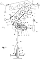
- FIG. 1 shows a schematic side view of a spinning station 1 of a spinning machine (ring spinning machine) with a drafting unit 2, which is provided with an input roller pair 3, 4, a central roller pair 5, 6 and an output roller pair 7, 8.
- a strap 12, 13 is guided around the center rollers 5, 6, each of which is held in its position shown around a cage (not shown in detail).
- the upper rollers 4, 6, 8 of the mentioned roller pairs are designed as pressure rollers which are rotatably mounted on a pivotably mounted pressure arm 10 via the axes 4a, 6a, 8a.
- Two adjacent drafting units 2 (twin drafting units) are assigned to a pressure arm 10.
- the pressure arm 10 is mounted pivotably about an axis 15 and, as shown schematically, is acted upon by a spring element 9.
- This spring element can also be an air hose, for example.
- the rollers 4, 6, 8 are pressed against the lower rollers 3, 5 and 7 of the roller pairs via the spring loading shown schematically.
- the roller pairs 3, 5, 7 are driven by a drive, not shown. Individual drives as well as other types of drive (gear wheels, toothed belts, etc.) can be used.
- Via the driven lower rollers 3, 5, 7, the pressure rollers 4, 6, 8 or the apron 13 are driven via friction via the apron 12.
- the peripheral speed of the driven roller 5 is slightly higher than the peripheral speed of the driven roller 3, so that the fiber material 11 fed to the drafting unit 2 in the form of a sliver between the input roller pair 3, 4 and the center roller pair 5, 6 is subjected to a pre-draft.
- the main draft of the fiber material 11 takes place between the central roller pair 5, 6 and the output roller pair 7, 8, the output roller 7 having a significantly higher peripheral speed than the central roller 5.
- the drawn fiber material 11 discharged from the respective pair of output rollers 7, 8 is deflected downward and reaches the area of a suction zone 16 of a subsequent suction drum 17 which is part of the compression device 46b according to the invention.
- the respective suction drum 17 is provided with perforations or openings 39 running on its circumference.
- a clamping roller 18 is provided for each of the suction drums 17, which rests on the respective suction drum 17 via a pressure load and forms a clamping line with it.
- the respective pinch roller 18 is rotatably mounted on an axis 19, which in a Guide slot 20 of a U-shaped receptacle of a pressure arm 21 is held.
- the axis 19 is slidably mounted within the guide slot 20 transversely to its longitudinal axis.
- a plunger protrudes into the guide slot 20 through an opening in the pressure arm 21, which rests on the outer circumference of the axle 19 and is acted upon by a pressure spring 22 shown schematically.
- the opening is attached approximately in the middle at the end of the guide slot 20 and opens into a substantially closed cavity of the pressure arm 21, in which the compression spring 22 is arranged. This is supported at the closed end of the cavity and the opposite end rests on a head of the plunger.
- the pressure arm 21 is mounted pivotably about an axis attached to its end in a bearing element. In this swivel position, the axes are shown schematically in Fig. 1 The stop edge shown is held transversely to its pivot axis at the end of a respective guide. Via the force of the compression spring 22, the pinch rollers 18, which are rotatably mounted on the pressure arm 21, are then loaded against the respective suction drum 17, the pinching line being created. The pressure arm 21 is pivoted past dead center until it rests on a stop. In this position, the axis 19 of the pinch rollers 18 is below the plane which runs through the pivot axis and the central axis of the suction drums 17, ie the pinch roller 33 is held in this position above dead center. Further details relating to the attachment and design of the pinch rollers 18 can be found in FIG CH705308 can be removed.
- the pressure lever 10 is then pivoted about its pivot axis 15 from an upper position, shown in dashed lines, to a lower position, in which a pressure force is exerted on the compression device 46b in FIG Direction of the roller 7 is exerted.
- the suction drum 17 connected to it is driven by the roller 7 via friction via a drive element 40 described further below.
- the fiber material 11 drawn and discharged by the drafting system 2 is fed to the subsequent suction zone 16 of the respective suction drum 17 and compressed in a known manner under the influence of the suction air flow generated.
- a deflecting screen arranged at a distance can also be attached above the suction zone 16 be, for example in the DE4426249 is shown and described. This publication also describes the process of compaction of the fiber material.
- a negative pressure source 26 is provided, which is connected to a central suction channel 27.
- the suction channel 27 is connected via a line 28, a flexible multiple nozzle connection 29, to the respective end of the suction channel 31 of the compression device 46b protruding in the direction of the suction channel 27.
- the flexibility of the multiple nozzle connection 29 enables the compacting device 46b to pivot about an axis.
- the compression device 46b has two lateral protrusions 30, which in relation to one another Fig. 2 Intervene explained holder.
- the multiple nozzle connection 29 shown schematically can be designed in such a way that, when two half-shells are joined together, it is connected to a suction channel 31 in a form-fitting manner and tightly to the outside.
- the construction and assembly of the half-shells in such a support element are from the WO2012068692A1 known.
- the spinning machine can advantageously be retrofitted with the compression device 46b.
- the structure, the mode of operation and advantages of the multiple nozzle connection 29 according to the invention are shown in FIG Fig. 2 explained in more detail.
- the pinch line generated by the pinch roller 18 simultaneously forms a so-called “rotation blocking gap", from which the fiber material 11 is fed in the conveying direction in the form of a compressed yarn 32 with rotation to a schematically shown ring spinning device.
- This is provided with a ring 33 and a rotor 34, the yarn being wound onto a sleeve 35 to form a bobbin 36 (cop).
- a thread guide 37 is arranged between the nipping line and the traveler 34.
- the ring 33 is attached to a ring frame 38 which moves up and down during the spinning process.
- FIGS. 2 and 3 show the multiple nozzle connection 29 according to the invention. It is used for the alternative connection of a compression device 46b, as shown in FIG Fig. 1 in context was explained with a ring spinning machine, or for connecting a suction pipe device 46a to the suction channel 27 of the ring spinning machine.
- Fig. 2 shows the multiple nozzle connection 29 according to the invention with a suction pipe device 46a connected to the suction channel 27 of the ring spinning machine.
- the suction device 46a consists of two suction pipes 47 which are arranged next to one another and which are connected via a central, round connecting element 50.
- a second connection between two suction pipes 47 is located at the front end of the suction pipe device 46a.
- the universal multiple nozzle connection 29 has a connection piece 42 with three connections 43 located next to one another, which are used depending on the connected device.
- An adapter or spacer 44 which can be connected to the connections 43 of the connecting piece 42, and a seal 45 are located between the connections 43 and the pre-sealing device or the suction pipe device 46a lateral connections 43 are closed.
- a suction tube device 46a can be connected to the lateral connections 43, the middle connection 43 then being closed by a plate 48.
- the compacting device 46b ( Fig. 1 , 3 ) or the suction tube device 46a ( Fig. 2 ) are detachably held by a holder of the multiple nozzle connection 29.
- the holder consists of two spaced apart holding elements 49.
- the suction pipe device 46a engages with the round connecting element 50 in the spaced apart holding elements 49, there is a detachable connection, for example a clip connection.
- the holding elements 49 are fastened to a holding profile 51 of the textile machine and at the same time hold the adapter or spacer 44 in place.
- Fig. 3 shows the multiple nozzle connection 29 according to the invention with a connected compression device 46b, as shown in FIG Fig. 1 was explained in connection with a ring spinning machine.
- the universal multiple nozzle connection 29 corresponds to the design of Fig. 2 , it has the three connection pieces 42 with the three connections 43 located next to one another.
- An adapter is located between the connections 43 and the pre-sealing device or the suction pipe device 46a or spacer 44, which can be connected to the connections 43 of the connecting piece 42, and a seal 45.
- the compression device 46b has two lateral protrusions 30 which engage in the two elements 49 of the holder.
- the compression device 46b can be connected to the central connection 43, the side connections 43 then being closed by plates 48.
- Fig. 4 shows a section AA through the multiple nozzle connection 29 with a connected suction device according to FIG Fig. 2 .
- the compression device 46b and the suction pipe device 46a can be pivoted about the aforementioned axis and can thus be releasably attached to the connection piece 42 by a rotating or tilting movement.
- the suction device 46a can assume two positions by means of two latching lugs 52, whereby in an upper position the suction pipes 47 are aligned at right angles to the suction channel or in alignment with the multiple nozzle connection and in a lower position the suction pipes 47 are inclined slightly downwards compared to the upper position are (not shown).
- the embodiment according to the invention is advantageous because the machine can be easily converted.
- the invention also relates to a method for releasably fastening the compression device 46b or the suction pipe device 46a to the multiple nozzle connection 29 of a textile machine, in particular a ring spinning machine.
Landscapes
- Engineering & Computer Science (AREA)
- Mechanical Engineering (AREA)
- Textile Engineering (AREA)
- Spinning Or Twisting Of Yarns (AREA)
Description
Die Erfindung bezieht sich auf einen Mehrfachdüsenanschluss einer Absaugleitung einer Textilmaschine nach dem unabhängigen Patentanspruches und auf eine damit ausgerüsteten Textilmaschine.The invention relates to a multiple nozzle connection of a suction line of a textile machine according to the independent patent claim and to a textile machine equipped therewith.
Aus der Praxis ist bereits eine Vielzahl von Ausführungen bekannt, wobei zum Kompaktieren (Verdichten) des von einer Streckwerkseinheit abgegebenen Fasergutes (Faserstrang) eine Verdichtungseinrichtung nachgeordnet ist. Im Anschluss an eine solche Verdichtungseinrichtung wird das verdichtete Fasergut, nach Passieren einer Klemmstelle, einer Drallerzeugungsvorrichtung zugeführt. Eine solche Drallerzeugungsvorrichtung besteht z.B. bei einer Ringspinnmaschine aus einem Läufer, der auf einem Ring umläuft, wobei das erzeugte Garn auf eine rotierende Hülse aufgewickelt wird. Als Verdichtungseinrichtungen kommen im Wesentlichen besaugte umlaufende, perforierte Saugtrommeln oder umlaufende, mit Perforationen versehene Riemchen zum Einsatz. Dabei wird unter Verwendung von entsprechenden Einsätzen innerhalb der Saugtrommel, bzw. innerhalb der umlaufenden Riemchen ein spezieller Saugbereich auf dem Verdichtungselement definiert. Derartige Einsätze können dabei z.B. mit entsprechend geformten Saugschlitzen versehen werden, an welche ein Unterdruck angelegt wird, wodurch eine entsprechende Luftströmung an der Peripherie des jeweiligen Verdichtungselementes erzeugt wird. Durch diese Luftströmung, welche im Wesentlichen quer zur Transportrichtung des Fasergutes ausgerichtet ist, werden insbesondere abstehende Fasern in das Garn mit eingebunden.A large number of designs are already known from practice, a compression device being arranged downstream for compacting (compressing) the fiber material (fiber strand) discharged from a drafting unit. Subsequent to such a compression device, the compressed fiber material is fed to a twist generating device after passing through a clamping point. Such a twist generating device consists, for example in a ring spinning machine, of a rotor which revolves on a ring, the yarn produced being wound onto a rotating tube. The compression devices used are essentially circumferential, perforated suction drums or circumferential aprons provided with perforations. A special suction area is defined on the compression element using appropriate inserts within the suction drum or within the circumferential aprons. Such inserts can, for example, be provided with appropriately shaped suction slots, to which a negative pressure is applied, whereby a corresponding air flow is generated on the periphery of the respective compression element. This air flow, which is oriented essentially transversely to the direction of transport of the fiber material, in particular also binds protruding fibers into the yarn.
Bei den bekannten Lösungen wird das von der Streckwerkseinheit abgegebene Fasergut oberhalb oder auch unterhalb der verwendeten Verdichtungsvorrichtungen geführt. Insbesondere beim Einsatz an einer Ringspinnmaschine ist es erforderlich, im Anschluss an die Saugzone eine zusätzliche Klemmstelle vorzusehen, um eine Drallsperrung zu erhalten.In the known solutions, the fiber material discharged from the drafting unit is guided above or below the compression devices used. Particularly when used on a ring spinning machine, it is necessary to provide an additional clamping point after the suction zone in order to obtain a twist lock.
Derartige solche Einrichtungen sind beispielsweise in den Veröffentlichungen
In der Praxis besteht die Forderung vorhandene Spinnmaschinen mit einer herkömmlichen Streckwerkseinheit mit einer solchen Verdichtungsvorrichtung nachzurüsten, um sich auch bei diesen Maschinen die Möglichkeit der Herstellung von qualitativ hochwertigen Garnen zu sichern. Es wurden deshalb Vorrichtungen vorgeschlagen, mit welchen herkömmliche Streckwerke mit einer solchen Verdichtungsvorrichtung nachgerüstet werden können. Eine solche ist beispielsweise aus der
In der veröffentlichten
Aus der
Bei den zuvor beschriebenen Ausführungen werden die Saugelemente, welche einem definierten Verdichtungsbereich zum Komprimieren des Fasergutes zugeordnet sind, über zusätzlich angeordnete Leitungen, die mit einer Unterdruckquelle verbunden sind, mit einem Unterdruck beaufschlagt.In the embodiments described above, the suction elements, which are assigned to a defined compression area for compressing the fiber material, are subjected to a negative pressure via additionally arranged lines which are connected to a negative pressure source.
Zur Vereinfachung derartiger Verdichtungsvorrichtungen, wobei eine einfache und schnelle Installation an konventionelle Streckwerkseinheiten ermöglicht wird, ohne dass zusätzliche Antriebselemente installiert werden müssen, wird in der
Nachteilig an dieser Ausführungsform ist jedoch, dass die Umrüstung der Textilmaschine von einer Verdichtungsvorrichtung zu einer konventionellen Fadenabsaugung relativ kosten- und zeitintensiv ist.The disadvantage of this embodiment, however, is that converting the textile machine from a compression device to a conventional thread suction device is relatively costly and time-consuming.
Der Erfindung liegt nunmehr die Aufgabe zu Grunde, die aus
Insbesondere wird diese Aufgabe durch eine Kombination aus einem Mehrfachdüsenanschluss und entweder einer Absaugvorrichtung oder einer Verdichtungsvorrichtung gemäß dem Anspruch 1 gelöst.In particular, this object is achieved by a combination of a multiple nozzle connection and either a suction device or a compression device according to
Diese erfindungsgemässe Ausführungsform ist vorteilhaft, da eine einfache Umrüstung der Maschine möglich ist. Weiter können vorteilhaft zwischen dem Anschlussstutzen und der Verdichtungsvorrichtung oder der Absaugvorrichtung ein Abstandhalter und eine Dichtung vorhanden sein, die eine Ausrichtung und eine Abdichtung der Verdichtungsvorrichtung oder der Absaugvorrichtung erlauben.This embodiment according to the invention is advantageous because the machine can be easily converted. Furthermore, a spacer and a seal can advantageously be present between the connecting piece and the compression device or the suction device, which allow an alignment and a sealing of the compression device or the suction device.
Lösbar und schwenkbar um eine Achse gehalten werden die Verdichtungsvorrichtung bzw. die Absaugrohrvorrichtung durch einen Halter des Mehrfachdüsenanschlusses. Der Halter kann aus zwei beabstandeten Halteelementen, wobei die Verdichtungsvorrichtung zwei seitliche Hervorhebungen und die Absaugrohrvorrichtung eine rundes Verbindungselement zum Verbinden mit den beabstandenten Halteelementen aufweist. Es kann sich dabei um eine Klipp-Verbindung handeln. Durch zwei Rastnasen, die in Verbindung mit Öffnungen in den Halteelementen stehen, kann die Absaugvorrichtung zwei Positionen einnehmen, wobei in einer oberen Position die Absaugrohre rechtwinklig zum Absaugkanal bzw. in einer Flucht mit dem Mehrfachdüsenanschluss ausgerichtet sind und in einer unteren Position die Absaugrohre im Vergleich zur oberen Position nach unten geneigt sind. Die Halteelemente können vorteilhaft an einem Halteprofil der Textilmaschine befestigt sein.The compression device or the suction pipe device are held detachably and pivotably about an axis by a holder of the multiple nozzle connection. The holder can consist of two spaced-apart holding elements, the compression device having two lateral protrusions and the suction pipe device having a round connecting element for connecting to the spaced-apart holding elements. It can be a clip connection. The suction device can assume two positions by means of two locking lugs that are connected to openings in the holding elements, with the suction pipes in an upper position being aligned at right angles to the suction channel or in alignment with the multiple nozzle connection and in a lower position the suction pipes in comparison to the upper position are inclined downwards. The holding elements can advantageously be attached to a holding profile of the textile machine.
Die Aufgabe wird auch gelöst durch eine Textilmaschine, die insbesondere Ringspinnmaschine ist, dadurch gekennzeichnet, dass sie eine erfindungsgemäße Kombination aus einem Mehrfachdüsenanschluss und einer Absaugvorrichtung oder einer Verdichtungsvorrichtung aufweist.The object is also achieved by a textile machine, which is in particular a ring spinning machine, characterized in that it has a combination according to the invention of a multiple nozzle connection and a suction device or a compression device.
Gemäß einer Ausführungsform der ersten Variante der Erfindung ist an den Mehrfachdüsenanschluss eine Verdichtungsvorrichtung angeschlossen, die folgende Merkmale umfasst
- zwei Saugtrommeln, wobei jeweils eine Saugtrommel einem Ausgangswalzenpaar einer Streckwerkseinheit der Textilmaschine zuordenbar ist, wobei das Ausgangswalzenpaar aus einer Ausgangsunterwalze und einer Ausgangsoberwalze besteht;
- wobei die Saugtrommeln auf einer, an einem Tragelement befestigten Welle mit einem Lager drehbar gelagert sind;
- wobei innerhalb des Tragelementes ein Saugkanal verläuft,
- wobei die Saugtrommeln jeweils ein Antriebselement aufweisen, das in Betriebsstellung mit der Ausgangsunterwalze eine Antriebsverbindung bildet, und
- wobei am Tragelement zwei Klemmwalzen drehbar auf einer gemeinsamen Achse mittig in einer Lagerung gelagert sind, wobei jede der Klemmwalzen zur Bildung einer Klemmlinie jeweils auf dem Aussenumfang einer der beiden Saugtrommeln unter Einwirkung einer Federbelastung aufliegen,
- wobei jeweils eine Saugtrommel dem Ausgangswalzenpaar einer Streckwerkseinheit zugeordnet ist,
- wobei am Tragelement zwei Klemmwalzen drehbar auf einer gemeinsamen Achse mittig gelagert sind, und
- wobei jede der Klemmwalzen zur Bildung einer Klemmlinie jeweils auf dem Aussenumfang einer der beiden Saugtrommeln unter Einwirkung einer Federbelastung aufliegen.
- two suction drums, one suction drum in each case being assignable to an output roller pair of a drafting unit of the textile machine, the output roller pair consisting of an output lower roller and an output upper roller;
- wherein the suction drums are rotatably mounted on a shaft attached to a support element with a bearing;
- wherein a suction channel runs within the support element,
- wherein the suction drums each have a drive element which, in the operating position, forms a drive connection with the output lower roller, and
- wherein two pinch rollers are rotatably mounted on a common axis in the middle of a bearing on the support element, each of the pinch rollers resting on the outer circumference of one of the two suction drums under the action of a spring load to form a nip line,
- where one suction drum is assigned to the pair of output rollers of a drafting unit,
- wherein two pinch rollers are rotatably mounted centrally on a common axis on the support element, and
- wherein each of the pinch rollers to form a pinch line rest on the outer circumference of one of the two suction drums under the action of a spring load.
Gemäß einer Ausführungsform der zweiten Variante der Erfindung ist an den Mehrfachdüsenanschluss alternativ eine Absaugvorrichtung anschliessbar, welche folgende Merkmale umfasst:
zwei beabstandete Absaugrohre, die durch mindestens ein Verbindungselement miteinander verbunden sind; und eine zentrale Platte, mit welchen ein mittlerer Anschluss des Anschlussstutzens verschliessbar ist. Vorteilhaft sind die Verdichtungsvorrichtung bzw. die Absaugrohrvorrichtung weiter durch den Halter des Mehrfachdüsenanschlusses lösbar und schwenkbar um eine Achse gehalten, wobei der Halter aus zwei beabstandeten Elementen besteht und an einem Halteprofil befestigbar ist, wobei die Absaugrohrvorrichtung zwei verschiedene Positionen einnehmen kann.According to one embodiment of the second variant of the invention, a suction device, which comprises the following features, can alternatively be connected to the multiple nozzle connection:
two spaced suction tubes that are connected to one another by at least one connecting element; and a central plate with which a central connection of the connecting piece can be closed. Advantageously, the compression device and the suction tube device are also held detachably and pivotably about an axis by the holder of the multiple nozzle connection, the holder consisting of two spaced elements and being attachable to a holding profile, the suction tube device being able to assume two different positions.
Die Erfindung bezieht sich auch auf ein Verfahren zur lösbaren Befestigung der Verdichtungsvorrichtung oder der Absaugrohrvorrichtung an dem Mehrfachdüsenanschluss einer Ringspinnmaschine.The invention also relates to a method for releasably fastening the compression device or the suction pipe device to the multiple nozzle connection of a ring spinning machine.
Weitere Vorteile der Erfindung sind anhand eines nachfolgend beschriebenen und gezeigten Ausführungsbeispiels zu entnehmen.Further advantages of the invention can be gathered from an exemplary embodiment described and shown below.
Die Erfindung wird anhand der beigefügten Figuren näher erläutert, wobei
- Fig. 1
- eine schematische Seitenansicht eines einer Spinnstelle einer Ringspinnmaschine;
- Fig. 2
- ein erfindungsgemässen Mehrfachdüsenanschluss mit angeschlossener Absaugrohrvorrichtung;
- Fig. 3
- ein erfindungsgemässen Mehrfachdüsenanschluss mit angeschlossener Verdichtungsvorrichtung; und
- Fig. 4
- einen Schnitt durch den Mehrfachdüsenanschluss mit angeschlossener Absaugvorrichtung gemäss der Linie A-A in der
Fig. 2 ;
- Fig. 1
- a schematic side view of a spinning station of a ring spinning machine;
- Fig. 2
- a multiple nozzle connection according to the invention with a connected suction tube device;
- Fig. 3
- a multiple nozzle connection according to the invention with a connected compression device; and
- Fig. 4
- a section through the multiple nozzle connection with attached suction device according to the line AA in FIG
Fig. 2 ;
Das von dem jeweiligen Ausgangswalzenpaar 7, 8 abgegebene verstreckte Fasergut 11 wird nach unten abgelenkt und gelangt in den Bereich einer Saugzone 16 einer nachfolgenden Saugtrommel 17, die Teil der erfindungsgemässen Verdichtungsvorrichtung 46b ist. Die jeweilige Saugtrommel 17 ist mit auf ihrem Umfang verlaufenden Perforationen, bzw. Öffnungen 39 versehen. Im Anschluss an die Saugzone 16 ist für jede der Saugtrommeln 17 eine Klemmwalze 18 vorgesehen, die über eine Druckbelastung auf der jeweiligen Saugtrommel 17 aufliegt und mit dieser eine Klemmlinie bildet. Dabei ist die jeweilige Klemmwalze 18 auf einer Achse 19 drehbar gelagert, welche in einem Führungsschlitz 20 einer U-förmigen Aufnahme eines Druckarmes 21 gehalten wird. Die Achse 19 ist innerhalb des Führungsschlitzes 20 quer zu ihrer Längsachse verschiebbar gelagert. In den Führungsschlitz 20 ragt durch eine Öffnung des Druckarmes 21 ein Stössel, welcher auf dem Aussenumfang der Achse 19 aufsitzt und von einer schematisch gezeigten Druckfeder 22 beaufschlagt wird. Die Öffnung ist etwa mittig am Ende des Führungsschlitzes 20 angebracht und mündet in einen, im Wesentlichen geschlossenen Hohlraum des Druckarmes 21, in welchem die Druckfeder 22 angeordnet ist. Diese stützt sich am geschlossenen Ende des Hohlraumes ab und liegt mit dem gegenüberliegenden Ende auf einem Kopf des Stössels auf.The drawn
Der Druckarm 21 wird schwenkbar um eine, an seinem Ende angebrachte Achse in einem Lagerelement gelagert. In dieser Schwenkstellung werden die Achsen über eine schematisch in
Anschliessend wird der Druckhebel 10 um seine Schwenkachse 15 von einer gestrichelt gezeichneten oberen Lage in eine untere Lage verschwenkt, in welcher über eine, mittels Schrauben 23 am Druckhebel 10 befestigte Blattfeder 24 und den an der Blattfeder befestigten Steg 25 eine Druckkraft auf die Verdichtungsvorrichtung 46b in Richtung der Walze 7 ausgeübt wird. Über ein weiter unten beschriebenes Antriebselement 40 wird die damit verbundene Saugtrommel 17 über Friktion von der Walze 7 angetrieben.The
In dieser "Betriebsstellung" wird das vom Streckwerk 2 verzogene und abgegebene Fasergut 11 der nachfolgenden Saugzone 16 der jeweiligen Saugtrommel 17 zugeführt und in bekannter Weise unter dem Einfluss des erzeugten Saugluftstromes verdichtet. Oberhalb der Saugzone 16 kann noch ein im Abstand angeordneter Umlenkschirm angebracht sein, wie beispielsweise in der
Zur Erzeugung des benötigten Unterdruckes im Bereich der Saugzone 16 ist eine Unterdruckquelle 26 vorgesehen, die mit einem zentralen Absaugkanal 27 in Verbindung steht. Der Absaugkanal 27 steht über eine Leitung 28, einen flexiblen Mehrfachdüsenanschluss 29 mit dem jeweiligen, in Richtung des Absaugkanals 27 ragenden Ende des Saugkanals 31 der Verdichtungsvorrichtung 46b, in Verbindung. Durch die Flexibilität des Mehrfachdüsenanschlusses 29 wird die Schwenkbarkeit der Verdichtungsvorrichtung 46b um eine Achse ermöglicht. Die Verdichtungseinrichtung 46b weist zu diesem Zweck zwei seitliche Hervorhebungen 30 auf, die in einen in Bezug auf
Die durch die Klemmwalze 18 erzeugte Klemmlinie bildet gleichzeitig einen so genannten "Drehungssperrspalt", von welchem das Fasergut 11 in der Förderrichtung in Form eines komprimierten Garnes 32 unter Drehungserteilung einer schematisch ge-zeigten Ringspinneinrichtung zugeführt wird. Diese ist mit einem Ring 33 und einem Läufer 34 versehen, wobei das Garn auf eine Hülse 35 zur Bildung einer Spule 36 (Kops) aufgewickelt wird. Zwischen der Klemmlinie und dem Läufer 34 ist ein Fadenführer 37 angeordnet. Der Ring 33 ist an einem Ringrahmen 38 befestigt, welcher während dem Spinnprozess eine Auf- und Abbewegung durchführt.The pinch line generated by the
Die Verdichtungsvorrichtung 46b (
Die erfindungsgemässe Ausführungsform ist vorteilhaft, da eine einfache Umrüstung der Maschine möglich ist. Die Erfindung bezieht sich auch auf ein Verfahren zur lösbaren Befestigung der Verdichtungsvorrichtung 46b oder der Absaugrohrvorrichtung 46a an dem Mehrfachdüsenanschluss 29 einer Textilmaschine, insbesondere Ringspinnmaschine.The embodiment according to the invention is advantageous because the machine can be easily converted. The invention also relates to a method for releasably fastening the
- 11
- SpinnstelleSpinning position
- 22
- StreckwerkseinheitDrafting unit
- 33
- EingangsunterwalzeEntry bottom roller
- 44th
- EingangsoberwalzeEntrance top roller
- 4a4a
- Achseaxis
- 55
- MittelunterwalzeMiddle lower roller
- 66th
- MitteloberwalzeMiddle top roller
- 6a6a
- Achseaxis
- 77th
- AusgangsunterwalzeExit bottom roller
- 7a7a
- Achseaxis
- 88th
- AusgangsoberwalzeExit top roller
- 8a8a
- Achseaxis
- 99
- FederelementSpring element
- 1010
- DruckarmLow pressure
- 1111
- FaserlunteFiber sliver
- 1212th
- RiemchenStraps
- 1313th
- RiemchenStraps
- 1414th
- SaugzoneSuction zone
- 1515th
- Achseaxis
- 1616
- SaugzoneSuction zone
- 1717th
- SaugtrommelSuction drum
- 1818th
- KlemmwalzePinch roller
- 1919th
-
Achse der Klemmwalzen 18Axis of the
pinch rollers 18 - 2020th
- Führungsschlitz / LagerungGuide slot / bearing
- 2121
- DruckarmLow pressure
- 2222nd
- DruckfederCompression spring
- 2323
- SchraubenScrews
- 2424
- BlattfederLeaf spring
- 2525th
- Stegweb
- 2626th
- UnterdruckquelleVacuum source
- 2727
- AbsaugkanalSuction duct
- 2828
- Leitungmanagement
- 2929
- KupplungselementCoupling element
- 3030th
- HervorhebungEmphasis
- 3131
- SaugkanalSuction channel
- 3232
- Garnyarn
- 3333
- Ringring
- 3434
- RingläuferRing traveler
- 3535
- KopsKops
- 3636
- SpuleKitchen sink
- 3737
- FadenführerThread guide
- 3838
- RingrahmenRing frame
- 3939
- Öffnungenopenings
- 4040
- Reibrad, AntriebsradFriction wheel, drive wheel
- 4141
- TragelementSupport element
- 4242
- AnschlussstutzenConnection piece
- 4343
- Anschlussconnection
- 4444
- AbstandshalterSpacers
- 4545
- Dichtungpoetry
- 46a46a
- AbsaugrohrvorrichtungSuction tube device
- 46b46b
- VerdichtungsvorrichtungCompaction device
- 4747
- AbsaugrohrSuction tube
- 4848
- Platteplate
- 4949
- HalteelementRetaining element
- 5050
- rundes Verbindungselementround connector
- 5151
- HalteprofilRetaining profile
- 5252
- RastnasenLocking lugs
Claims (13)
- Combination of a multiple nozzle connector (29) and either a suction device (46a) or a compaction device (46b), wherein the multiple nozzle connector (29) is connectable to a suction channel (27) of a textile machine, in particular a ring spinning machine, comprising a connecting piece (42) for alternative connection of the compaction device (46b) or the suction tube device (46a) to the suction channel (27) of the textile machine via at least one suction tube (47), wherein the connecting piece (42) has three connectors (43) located next to one another, wherein, alternatively, the compaction device (46b) is detachably connected to the central connector (43), wherein the lateral connectors (43) are closed, or the suction tube device (46a), which has two suction tubes (47), is detachably connected to the lateral connectors (43), wherein the central connector (43) is closed.
- Combination according to claim 1, characterized in that the suction tube device (46a) can assume two different positions, the suction tube or tubes (47) being aligned with the multiple nozzle connector in a first position and the suction tube or tubes (47) being inclined downward in comparison with the upper position in a second position.
- Combination according to either of claims 1 to 2, characterized in that a spacer (44) and a seal (45) are present between the connecting piece (42) and the compaction device (46b) or the suction device (46a).
- Combination according to any of claims 1 to 3, characterized in that the compaction device (46b) and the suction tube device (46a) are held by a holder of the multiple nozzle connector (29) in a detachable manner and so as to be pivotable about an axis, which holder consists of two spaced-apart holding elements (49, the compaction device (46b) having two lateral protrusions (30) and the suction tube device (46a) having a central connecting element (50) for releasable connection to the spaced-apart holding elements (49).
- Combination according to the preceding claim, characterized in that the holding elements (49) can be fastened to a holding profile (51) of the textile machine.
- Textile machine, in particular a ring spinning machine, characterized in that said textile machine has a combination of a multiple nozzle connector (29) and either a suction device (46a) or a compaction device (46b) according to any of the preceding claims, comprising a connecting piece (42) for alternative connection of the compaction device (46b) or the suction tube device (46a) to the suction channel (27) of the textile machine via at least one suction tube (47), the connecting piece (42) having three connectors (43) located next to one another, the compaction device (46b) alternatively being detachably connected to a central connector (43), the lateral connectors (43) being closed, or a suction tube device (46a), which has two suction tubes (47), being detachably connected to the lateral connectors (43), the central connector (43) being closed.
- Textile machine according to the preceding claim, characterized in that the compaction device (46b) can be detachably connected to the connecting piece (42), comprising• two suction drums (17), it being possible for a suction drum (17) to be associated with a pair of output rollers (7, 8) of a drawing unit (2) of the textile machine in each case, the pair of output rollers (7, 8) consisting of a lower output roller (7) and an upper output roller (8);• wherein the suction drums (17) is rotatably mounted on a shaft attached to a support element (41) by means of a bearing;• wherein a suction channel (31) extends inside the support element (41),• wherein the suction drums (17) each have a drive element (40) which, in the operating position, forms a drive connection together with the output lower roller (7), and• wherein two nip rollers (18) are rotatably mounted centrally on a common axle (19) in a bearing (20) on the support element (41), each of the nip rollers (18), in order to form a nip line, resting on the outer circumference of one of the two suction drums (17) under the action of a spring load,• wherein a suction drum (17) is associated with the pair of output rollers (7, 8) of a drawing unit (2) in each case,• wherein two nip rollers (18) are rotatably mounted centrally on a common axle (19) on the support element (42), and• wherein each of the nip rollers (18), in order to form a nip line, rest on the outer circumference of one of the two suction drums (17) under the action of a spring load.
- Textile machine according to either of the preceding claims 6 or 7, characterized in that the suction tube device (46a) can be detachably connected to the connecting piece (42), comprising• two spaced-apart suction tubes (47) which are interconnected by at least one connecting element (50); and• a central plate (48), by means of which a central connector (43) of the connecting piece (42) can be closed.
- Textile machine according to any of the preceding claims 6 to 8, characterized in that the compaction device (46b) and the suction tube device (46a) are detachably held on the multiple nozzle connector (29) by a holder having two holding elements (49).
- Textile machine according to the preceding claim, characterized in that the compaction device (46b) and the suction tube device (46a) are detachably held by the holder, the compaction device (46b) having two lateral protrusions (30), and the suction tube device (46a) having a central connecting element (50) for connecting to the spaced-apart holding elements (49).
- Textile machine according to either claim 9 or claim 10, characterized in that the compaction device (46b) and the suction tube device (46a) are held by the holder of the multiple nozzle connector (29) in a detachable manner and so as to be pivotable about an axis, which holder consists of two spaced-apart holding elements (49) and can be fastened to a holding profile (51), it being possible for the suction tube device (46a) to assume two different positions.
- Textile machine according to any of the preceding claims 6 to 11, characterized in that a spacer (44) and a seal (45) are located between the compaction device (46b) or the suction tube device (46a) and a connecting piece (42).
- Method for operating a textile machine, in particular a ring spinning machine, characterized in that said textile machine has a combination of a multiple nozzle connector (29) and either a suction device (46a) or a compaction device (46b) according to any of the preceding claims 1 to 5, comprising the method step of releasably fastening the compaction device or the suction tube device (46a) to the multiple nozzle connector (29).
Applications Claiming Priority (2)
| Application Number | Priority Date | Filing Date | Title |
|---|---|---|---|
| CH01031/17A CH714068A1 (en) | 2017-08-17 | 2017-08-17 | Multiple nozzle connection of a textile machine and textile machine. |
| PCT/IB2018/055406 WO2019034946A1 (en) | 2017-08-17 | 2018-07-20 | Multiple nozzle junction of a textile machine, textile machine, and method for operating a textile machine |
Publications (2)
| Publication Number | Publication Date |
|---|---|
| EP3669021A1 EP3669021A1 (en) | 2020-06-24 |
| EP3669021B1 true EP3669021B1 (en) | 2021-09-01 |
Family
ID=63244656
Family Applications (1)
| Application Number | Title | Priority Date | Filing Date |
|---|---|---|---|
| EP18755914.1A Active EP3669021B1 (en) | 2017-08-17 | 2018-07-20 | Multiple nozzle junction of a textile machine, textile machine, and method for operating a textile machine |
Country Status (6)
| Country | Link |
|---|---|
| US (1) | US20210156052A1 (en) |
| EP (1) | EP3669021B1 (en) |
| JP (1) | JP2020531701A (en) |
| CN (1) | CN110997993A (en) |
| CH (1) | CH714068A1 (en) |
| WO (1) | WO2019034946A1 (en) |
Families Citing this family (1)
| Publication number | Priority date | Publication date | Assignee | Title |
|---|---|---|---|---|
| DE102018005732A1 (en) * | 2018-07-20 | 2020-01-23 | Saurer Technologies GmbH & Co. KG | Thread tension influencing device for a twisting or cabling machine |
Family Cites Families (24)
| Publication number | Priority date | Publication date | Assignee | Title |
|---|---|---|---|---|
| DE10050089C2 (en) | 2000-03-08 | 2002-06-27 | Zinser Textilmaschinen Gmbh | Drafting system for a spinning machine |
| JPS6094625A (en) * | 1983-10-26 | 1985-05-27 | Mitsubishi Rayon Co Ltd | Production of particular slub yarn |
| DE9015353U1 (en) * | 1990-11-08 | 1991-03-07 | Maschinenfabrik Rieter Ag, Winterthur | Device for suctioning fibre material, fluff or similar from textile machines |
| DE4426249C2 (en) | 1994-07-25 | 2003-08-07 | Rieter Ag Maschf | Spinning process and spinning machine with covered suction roll on the drafting system |
| DE19846268C2 (en) | 1998-03-31 | 2002-07-04 | Schurr Stahlecker & Grill | Device for compacting a stretched fiber composite |
| DE19815050B4 (en) | 1998-04-03 | 2005-09-22 | Saurer Gmbh & Co. Kg | Compression drafting system for a spinning machine |
| JP2000034629A (en) * | 1998-07-15 | 2000-02-02 | Toyota Autom Loom Works Ltd | Cotton-gathering controller of centralized cotton- gathering apparatus in spinning machine |
| DE10018480A1 (en) | 2000-04-14 | 2001-10-18 | Stahlecker Fritz | Condensing zone for a drawn sliver at a drawing unit, comprises a structured sliver carrier belt speed to compensate for the increased belt path length through the angled guide edge(s) at the suction slit(s) |
| DE10061405A1 (en) * | 2000-12-09 | 2002-06-13 | Rieter Ag Maschf | Textile fibre drawing machine has fibre suction tubes separated from a suction duct by a collector box |
| DE10227463C1 (en) | 2002-06-20 | 2003-10-16 | Zinser Textilmaschinen Gmbh | Ring spinning machine with stretching mechanism and compression system, has pressure unit extended to mount drive roller of compression system |
| ES2215487B1 (en) | 2004-03-11 | 2005-08-01 | Pinter, S.A. | DRIVING DEVICE FOR FIBER CONDENSATION MECHANISMS IN STYLING TRAINING OF SPINDING MACHINES. |
| JP4419703B2 (en) | 2004-06-22 | 2010-02-24 | 株式会社豊田自動織機 | Fiber bundle concentrator in spinning machine |
| CN100462488C (en) | 2004-06-23 | 2009-02-18 | 倪远 | Condensation and condenser for tight spinning whisker |
| CN2851298Y (en) | 2005-11-04 | 2006-12-27 | 倪远 | Compact spinning device of ring frame |
| CN101275316B (en) * | 2008-01-22 | 2010-07-14 | 宁波德昌精密纺织机械有限公司 | Air drafting device for compact spinning |
| CH699713A2 (en) * | 2008-10-13 | 2010-04-15 | Rieter Ag Maschf | Spinning machine such as ring spinning machine, has machine frame, central suction device and multiple spinning points arranged on machine frame |
| CN201416061Y (en) * | 2009-06-02 | 2010-03-03 | 杭州中亚布艺有限公司 | Dust collector dedicated for yarn machine |
| CH704133A2 (en) | 2010-11-26 | 2012-05-31 | Rieter Ag Maschf | Device for compressing a sliver on a spinning machine. |
| CH704137A1 (en) * | 2010-11-26 | 2012-05-31 | Rieter Ag Maschf | Device for compacting a fiber structure on a spinning machine and spinning machine. |
| ITMI20110585A1 (en) * | 2011-04-08 | 2012-10-09 | Savio Macchine Tessili Spa | SYSTEM FOR THE COLLECTION AND RECOVERY OF ROCKING SFRIDES |
| JP2013079478A (en) * | 2011-09-21 | 2013-05-02 | Murata Mach Ltd | Draft machine, spinning unit and spinning machine |
| JP2014231654A (en) * | 2013-05-29 | 2014-12-11 | 株式会社豊田自動織機 | Pneumatic device for spinning machine |
| CN105463639A (en) * | 2015-12-31 | 2016-04-06 | 湖州南浔石淙盛艳丝绸有限公司 | Textile machine with dust collection system |
| CN107354546B (en) * | 2017-08-04 | 2020-05-15 | 南通德和布业有限公司 | Weaving machine weaving dirt collection device |
-
2017
- 2017-08-17 CH CH01031/17A patent/CH714068A1/en not_active Application Discontinuation
-
2018
- 2018-07-20 US US16/639,346 patent/US20210156052A1/en not_active Abandoned
- 2018-07-20 JP JP2020508504A patent/JP2020531701A/en not_active Withdrawn
- 2018-07-20 CN CN201880054162.XA patent/CN110997993A/en active Pending
- 2018-07-20 EP EP18755914.1A patent/EP3669021B1/en active Active
- 2018-07-20 WO PCT/IB2018/055406 patent/WO2019034946A1/en unknown
Also Published As
| Publication number | Publication date |
|---|---|
| WO2019034946A1 (en) | 2019-02-21 |
| CH714068A1 (en) | 2019-02-28 |
| EP3669021A1 (en) | 2020-06-24 |
| JP2020531701A (en) | 2020-11-05 |
| US20210156052A1 (en) | 2021-05-27 |
| CN110997993A (en) | 2020-04-10 |
Similar Documents
| Publication | Publication Date | Title |
|---|---|---|
| EP2643507B1 (en) | Spinning machine comprising a compaction device | |
| EP2828423B1 (en) | Carrier element for a compaction device | |
| EP2643506B1 (en) | Drive device for a compaction device on a spinning machine | |
| EP2737116B1 (en) | Spinning machine having a compaction device | |
| EP3110992B1 (en) | Compressing device having a suction drum | |
| WO2002038842A1 (en) | Device for compressing a fibre assembly in a spinning machine | |
| EP3669021B1 (en) | Multiple nozzle junction of a textile machine, textile machine, and method for operating a textile machine | |
| EP2551389B1 (en) | Compaction sensor for a spinning machine | |
| EP2852700B1 (en) | Fastening means for a fibre condensing module on a spinning machine | |
| WO2002042535A1 (en) | Device on a spinning machine for compressing a fibre bundle | |
| EP3724383A1 (en) | Drawing frame for a spinning machine comprising a compaction device | |
| WO2002034977A1 (en) | Device on a spinning machine for compacting a fibre bundle | |
| WO2018234912A1 (en) | Compression device for a spinning machine | |
| DE10012019B4 (en) | Draw frame for spinning machine | |
| DE10144570A1 (en) | Spinning machine with suction device | |
| EP1921184A2 (en) | Roving guide for a stretching unit | |
| EP3741889B1 (en) | Condensing device for a spinning machine, drawing frame with the condensing device and method for operating the condensing device | |
| DE102016106207A1 (en) | Absorbent body for a pneumatically operated fiber compression device and thus equipped spinning machine | |
| DE10063727A1 (en) | Reinforcement for a suction channel of a fiber bundling device of a spinning machine | |
| DE10235876A1 (en) | Spinning assembly fibre inlet cover is retained in position by pincer-operated pincer arms with snap fit lock | |
| WO2004015177A1 (en) | Exchangeable attachment for a fibre-bundling device on a spinning machine | |
| DE10031117A1 (en) | Stretching and compression unit on spinning machine includes clamping roller moved out of operational position into idle position e.g. on binding | |
| CH709798A1 (en) | Cleaning apparatus for cleaning suction drum surfaces a compacting device for spinning machines, and the compacting device, and the ring spinning machine. |
Legal Events
| Date | Code | Title | Description |
|---|---|---|---|
| STAA | Information on the status of an ep patent application or granted ep patent |
Free format text: STATUS: UNKNOWN |
|
| STAA | Information on the status of an ep patent application or granted ep patent |
Free format text: STATUS: THE INTERNATIONAL PUBLICATION HAS BEEN MADE |
|
| PUAI | Public reference made under article 153(3) epc to a published international application that has entered the european phase |
Free format text: ORIGINAL CODE: 0009012 |
|
| STAA | Information on the status of an ep patent application or granted ep patent |
Free format text: STATUS: REQUEST FOR EXAMINATION WAS MADE |
|
| 17P | Request for examination filed |
Effective date: 20200313 |
|
| AK | Designated contracting states |
Kind code of ref document: A1 Designated state(s): AL AT BE BG CH CY CZ DE DK EE ES FI FR GB GR HR HU IE IS IT LI LT LU LV MC MK MT NL NO PL PT RO RS SE SI SK SM TR |
|
| AX | Request for extension of the european patent |
Extension state: BA ME |
|
| DAV | Request for validation of the european patent (deleted) | ||
| DAX | Request for extension of the european patent (deleted) | ||
| REG | Reference to a national code |
Ref country code: DE Ref legal event code: R079 Ref document number: 502018006879 Country of ref document: DE Free format text: PREVIOUS MAIN CLASS: D01H0001140000 Ipc: D01H0005660000 |
|
| GRAP | Despatch of communication of intention to grant a patent |
Free format text: ORIGINAL CODE: EPIDOSNIGR1 |
|
| STAA | Information on the status of an ep patent application or granted ep patent |
Free format text: STATUS: GRANT OF PATENT IS INTENDED |
|
| RIC1 | Information provided on ipc code assigned before grant |
Ipc: D01H 5/66 20060101AFI20210304BHEP Ipc: D01H 5/72 20060101ALI20210304BHEP |
|
| INTG | Intention to grant announced |
Effective date: 20210329 |
|
| GRAS | Grant fee paid |
Free format text: ORIGINAL CODE: EPIDOSNIGR3 |
|
| GRAA | (expected) grant |
Free format text: ORIGINAL CODE: 0009210 |
|
| STAA | Information on the status of an ep patent application or granted ep patent |
Free format text: STATUS: THE PATENT HAS BEEN GRANTED |
|
| AK | Designated contracting states |
Kind code of ref document: B1 Designated state(s): AL AT BE BG CH CY CZ DE DK EE ES FI FR GB GR HR HU IE IS IT LI LT LU LV MC MK MT NL NO PL PT RO RS SE SI SK SM TR |
|
| REG | Reference to a national code |
Ref country code: GB Ref legal event code: FG4D Free format text: NOT ENGLISH |
|
| REG | Reference to a national code |
Ref country code: CH Ref legal event code: EP Ref country code: AT Ref legal event code: REF Ref document number: 1426351 Country of ref document: AT Kind code of ref document: T Effective date: 20210915 |
|
| REG | Reference to a national code |
Ref country code: DE Ref legal event code: R096 Ref document number: 502018006879 Country of ref document: DE |
|
| REG | Reference to a national code |
Ref country code: IE Ref legal event code: FG4D Free format text: LANGUAGE OF EP DOCUMENT: GERMAN |
|
| REG | Reference to a national code |
Ref country code: LT Ref legal event code: MG9D |
|
| REG | Reference to a national code |
Ref country code: NL Ref legal event code: MP Effective date: 20210901 |
|
| PG25 | Lapsed in a contracting state [announced via postgrant information from national office to epo] |
Ref country code: LT Free format text: LAPSE BECAUSE OF FAILURE TO SUBMIT A TRANSLATION OF THE DESCRIPTION OR TO PAY THE FEE WITHIN THE PRESCRIBED TIME-LIMIT Effective date: 20210901 Ref country code: BG Free format text: LAPSE BECAUSE OF FAILURE TO SUBMIT A TRANSLATION OF THE DESCRIPTION OR TO PAY THE FEE WITHIN THE PRESCRIBED TIME-LIMIT Effective date: 20211201 Ref country code: NO Free format text: LAPSE BECAUSE OF FAILURE TO SUBMIT A TRANSLATION OF THE DESCRIPTION OR TO PAY THE FEE WITHIN THE PRESCRIBED TIME-LIMIT Effective date: 20211201 Ref country code: SE Free format text: LAPSE BECAUSE OF FAILURE TO SUBMIT A TRANSLATION OF THE DESCRIPTION OR TO PAY THE FEE WITHIN THE PRESCRIBED TIME-LIMIT Effective date: 20210901 Ref country code: RS Free format text: LAPSE BECAUSE OF FAILURE TO SUBMIT A TRANSLATION OF THE DESCRIPTION OR TO PAY THE FEE WITHIN THE PRESCRIBED TIME-LIMIT Effective date: 20210901 Ref country code: HR Free format text: LAPSE BECAUSE OF FAILURE TO SUBMIT A TRANSLATION OF THE DESCRIPTION OR TO PAY THE FEE WITHIN THE PRESCRIBED TIME-LIMIT Effective date: 20210901 Ref country code: FI Free format text: LAPSE BECAUSE OF FAILURE TO SUBMIT A TRANSLATION OF THE DESCRIPTION OR TO PAY THE FEE WITHIN THE PRESCRIBED TIME-LIMIT Effective date: 20210901 Ref country code: ES Free format text: LAPSE BECAUSE OF FAILURE TO SUBMIT A TRANSLATION OF THE DESCRIPTION OR TO PAY THE FEE WITHIN THE PRESCRIBED TIME-LIMIT Effective date: 20210901 |
|
| PG25 | Lapsed in a contracting state [announced via postgrant information from national office to epo] |
Ref country code: PL Free format text: LAPSE BECAUSE OF FAILURE TO SUBMIT A TRANSLATION OF THE DESCRIPTION OR TO PAY THE FEE WITHIN THE PRESCRIBED TIME-LIMIT Effective date: 20210901 Ref country code: LV Free format text: LAPSE BECAUSE OF FAILURE TO SUBMIT A TRANSLATION OF THE DESCRIPTION OR TO PAY THE FEE WITHIN THE PRESCRIBED TIME-LIMIT Effective date: 20210901 Ref country code: GR Free format text: LAPSE BECAUSE OF FAILURE TO SUBMIT A TRANSLATION OF THE DESCRIPTION OR TO PAY THE FEE WITHIN THE PRESCRIBED TIME-LIMIT Effective date: 20211202 |
|
| PG25 | Lapsed in a contracting state [announced via postgrant information from national office to epo] |
Ref country code: IS Free format text: LAPSE BECAUSE OF FAILURE TO SUBMIT A TRANSLATION OF THE DESCRIPTION OR TO PAY THE FEE WITHIN THE PRESCRIBED TIME-LIMIT Effective date: 20220101 Ref country code: SM Free format text: LAPSE BECAUSE OF FAILURE TO SUBMIT A TRANSLATION OF THE DESCRIPTION OR TO PAY THE FEE WITHIN THE PRESCRIBED TIME-LIMIT Effective date: 20210901 Ref country code: SK Free format text: LAPSE BECAUSE OF FAILURE TO SUBMIT A TRANSLATION OF THE DESCRIPTION OR TO PAY THE FEE WITHIN THE PRESCRIBED TIME-LIMIT Effective date: 20210901 Ref country code: RO Free format text: LAPSE BECAUSE OF FAILURE TO SUBMIT A TRANSLATION OF THE DESCRIPTION OR TO PAY THE FEE WITHIN THE PRESCRIBED TIME-LIMIT Effective date: 20210901 Ref country code: PT Free format text: LAPSE BECAUSE OF FAILURE TO SUBMIT A TRANSLATION OF THE DESCRIPTION OR TO PAY THE FEE WITHIN THE PRESCRIBED TIME-LIMIT Effective date: 20220103 Ref country code: NL Free format text: LAPSE BECAUSE OF FAILURE TO SUBMIT A TRANSLATION OF THE DESCRIPTION OR TO PAY THE FEE WITHIN THE PRESCRIBED TIME-LIMIT Effective date: 20210901 Ref country code: EE Free format text: LAPSE BECAUSE OF FAILURE TO SUBMIT A TRANSLATION OF THE DESCRIPTION OR TO PAY THE FEE WITHIN THE PRESCRIBED TIME-LIMIT Effective date: 20210901 Ref country code: CZ Free format text: LAPSE BECAUSE OF FAILURE TO SUBMIT A TRANSLATION OF THE DESCRIPTION OR TO PAY THE FEE WITHIN THE PRESCRIBED TIME-LIMIT Effective date: 20210901 Ref country code: AL Free format text: LAPSE BECAUSE OF FAILURE TO SUBMIT A TRANSLATION OF THE DESCRIPTION OR TO PAY THE FEE WITHIN THE PRESCRIBED TIME-LIMIT Effective date: 20210901 |
|
| REG | Reference to a national code |
Ref country code: DE Ref legal event code: R097 Ref document number: 502018006879 Country of ref document: DE |
|
| PLBE | No opposition filed within time limit |
Free format text: ORIGINAL CODE: 0009261 |
|
| STAA | Information on the status of an ep patent application or granted ep patent |
Free format text: STATUS: NO OPPOSITION FILED WITHIN TIME LIMIT |
|
| PG25 | Lapsed in a contracting state [announced via postgrant information from national office to epo] |
Ref country code: DK Free format text: LAPSE BECAUSE OF FAILURE TO SUBMIT A TRANSLATION OF THE DESCRIPTION OR TO PAY THE FEE WITHIN THE PRESCRIBED TIME-LIMIT Effective date: 20210901 |
|
| 26N | No opposition filed |
Effective date: 20220602 |
|
| PG25 | Lapsed in a contracting state [announced via postgrant information from national office to epo] |
Ref country code: SI Free format text: LAPSE BECAUSE OF FAILURE TO SUBMIT A TRANSLATION OF THE DESCRIPTION OR TO PAY THE FEE WITHIN THE PRESCRIBED TIME-LIMIT Effective date: 20210901 |
|
| PGFP | Annual fee paid to national office [announced via postgrant information from national office to epo] |
Ref country code: TR Payment date: 20220713 Year of fee payment: 5 Ref country code: IT Payment date: 20220726 Year of fee payment: 5 Ref country code: DE Payment date: 20220620 Year of fee payment: 5 |
|
| PG25 | Lapsed in a contracting state [announced via postgrant information from national office to epo] |
Ref country code: MC Free format text: LAPSE BECAUSE OF FAILURE TO SUBMIT A TRANSLATION OF THE DESCRIPTION OR TO PAY THE FEE WITHIN THE PRESCRIBED TIME-LIMIT Effective date: 20210901 |
|
| REG | Reference to a national code |
Ref country code: CH Ref legal event code: PL |
|
| GBPC | Gb: european patent ceased through non-payment of renewal fee |
Effective date: 20220720 |
|
| REG | Reference to a national code |
Ref country code: BE Ref legal event code: MM Effective date: 20220731 |
|
| PG25 | Lapsed in a contracting state [announced via postgrant information from national office to epo] |
Ref country code: LU Free format text: LAPSE BECAUSE OF NON-PAYMENT OF DUE FEES Effective date: 20220720 Ref country code: LI Free format text: LAPSE BECAUSE OF NON-PAYMENT OF DUE FEES Effective date: 20220731 Ref country code: FR Free format text: LAPSE BECAUSE OF NON-PAYMENT OF DUE FEES Effective date: 20220731 Ref country code: CH Free format text: LAPSE BECAUSE OF NON-PAYMENT OF DUE FEES Effective date: 20220731 |
|
| PG25 | Lapsed in a contracting state [announced via postgrant information from national office to epo] |
Ref country code: GB Free format text: LAPSE BECAUSE OF NON-PAYMENT OF DUE FEES Effective date: 20220720 Ref country code: BE Free format text: LAPSE BECAUSE OF NON-PAYMENT OF DUE FEES Effective date: 20220731 |
|
| PG25 | Lapsed in a contracting state [announced via postgrant information from national office to epo] |
Ref country code: IE Free format text: LAPSE BECAUSE OF NON-PAYMENT OF DUE FEES Effective date: 20220720 |
|
| REG | Reference to a national code |
Ref country code: DE Ref legal event code: R119 Ref document number: 502018006879 Country of ref document: DE |
|
| PG25 | Lapsed in a contracting state [announced via postgrant information from national office to epo] |
Ref country code: MK Free format text: LAPSE BECAUSE OF FAILURE TO SUBMIT A TRANSLATION OF THE DESCRIPTION OR TO PAY THE FEE WITHIN THE PRESCRIBED TIME-LIMIT Effective date: 20210901 Ref country code: DE Free format text: LAPSE BECAUSE OF NON-PAYMENT OF DUE FEES Effective date: 20240201 Ref country code: CY Free format text: LAPSE BECAUSE OF FAILURE TO SUBMIT A TRANSLATION OF THE DESCRIPTION OR TO PAY THE FEE WITHIN THE PRESCRIBED TIME-LIMIT Effective date: 20210901 |
|
| PG25 | Lapsed in a contracting state [announced via postgrant information from national office to epo] |
Ref country code: HU Free format text: LAPSE BECAUSE OF FAILURE TO SUBMIT A TRANSLATION OF THE DESCRIPTION OR TO PAY THE FEE WITHIN THE PRESCRIBED TIME-LIMIT; INVALID AB INITIO Effective date: 20180720 |
|
| PG25 | Lapsed in a contracting state [announced via postgrant information from national office to epo] |
Ref country code: IT Free format text: LAPSE BECAUSE OF NON-PAYMENT OF DUE FEES Effective date: 20230720 |
|
| REG | Reference to a national code |
Ref country code: AT Ref legal event code: MM01 Ref document number: 1426351 Country of ref document: AT Kind code of ref document: T Effective date: 20230720 |