EP2825250B1 - Schlauchadapter zum beeinflussen des drucks innerhalb eines schlauchabschnitts während einer medizinischen behandlung - Google Patents
Schlauchadapter zum beeinflussen des drucks innerhalb eines schlauchabschnitts während einer medizinischen behandlung Download PDFInfo
- Publication number
- EP2825250B1 EP2825250B1 EP13709773.9A EP13709773A EP2825250B1 EP 2825250 B1 EP2825250 B1 EP 2825250B1 EP 13709773 A EP13709773 A EP 13709773A EP 2825250 B1 EP2825250 B1 EP 2825250B1
- Authority
- EP
- European Patent Office
- Prior art keywords
- hose
- dialysis fluid
- pressure
- adapter
- tubing
- Prior art date
- Legal status (The legal status is an assumption and is not a legal conclusion. Google has not performed a legal analysis and makes no representation as to the accuracy of the status listed.)
- Active
Links
Images

Classifications
-
- A—HUMAN NECESSITIES
- A61—MEDICAL OR VETERINARY SCIENCE; HYGIENE
- A61M—DEVICES FOR INTRODUCING MEDIA INTO, OR ONTO, THE BODY; DEVICES FOR TRANSDUCING BODY MEDIA OR FOR TAKING MEDIA FROM THE BODY; DEVICES FOR PRODUCING OR ENDING SLEEP OR STUPOR
- A61M39/00—Tubes, tube connectors, tube couplings, valves, access sites or the like, specially adapted for medical use
- A61M39/10—Tube connectors; Tube couplings
-
- A—HUMAN NECESSITIES
- A61—MEDICAL OR VETERINARY SCIENCE; HYGIENE
- A61M—DEVICES FOR INTRODUCING MEDIA INTO, OR ONTO, THE BODY; DEVICES FOR TRANSDUCING BODY MEDIA OR FOR TAKING MEDIA FROM THE BODY; DEVICES FOR PRODUCING OR ENDING SLEEP OR STUPOR
- A61M1/00—Suction or pumping devices for medical purposes; Devices for carrying-off, for treatment of, or for carrying-over, body-liquids; Drainage systems
- A61M1/14—Dialysis systems; Artificial kidneys; Blood oxygenators ; Reciprocating systems for treatment of body fluids, e.g. single needle systems for hemofiltration or pheresis
- A61M1/16—Dialysis systems; Artificial kidneys; Blood oxygenators ; Reciprocating systems for treatment of body fluids, e.g. single needle systems for hemofiltration or pheresis with membranes
- A61M1/1654—Dialysates therefor
- A61M1/1656—Apparatus for preparing dialysates
- A61M1/166—Heating
-
- A—HUMAN NECESSITIES
- A61—MEDICAL OR VETERINARY SCIENCE; HYGIENE
- A61M—DEVICES FOR INTRODUCING MEDIA INTO, OR ONTO, THE BODY; DEVICES FOR TRANSDUCING BODY MEDIA OR FOR TAKING MEDIA FROM THE BODY; DEVICES FOR PRODUCING OR ENDING SLEEP OR STUPOR
- A61M39/00—Tubes, tube connectors, tube couplings, valves, access sites or the like, specially adapted for medical use
- A61M39/22—Valves or arrangement of valves
- A61M39/24—Check- or non-return valves
-
- A—HUMAN NECESSITIES
- A61—MEDICAL OR VETERINARY SCIENCE; HYGIENE
- A61M—DEVICES FOR INTRODUCING MEDIA INTO, OR ONTO, THE BODY; DEVICES FOR TRANSDUCING BODY MEDIA OR FOR TAKING MEDIA FROM THE BODY; DEVICES FOR PRODUCING OR ENDING SLEEP OR STUPOR
- A61M5/00—Devices for bringing media into the body in a subcutaneous, intra-vascular or intramuscular way; Accessories therefor, e.g. filling or cleaning devices, arm-rests
- A61M5/14—Infusion devices, e.g. infusing by gravity; Blood infusion; Accessories therefor
- A61M5/168—Means for controlling media flow to the body or for metering media to the body, e.g. drip meters, counters ; Monitoring media flow to the body
- A61M5/16804—Flow controllers
- A61M5/16813—Flow controllers by controlling the degree of opening of the flow line
-
- A—HUMAN NECESSITIES
- A61—MEDICAL OR VETERINARY SCIENCE; HYGIENE
- A61M—DEVICES FOR INTRODUCING MEDIA INTO, OR ONTO, THE BODY; DEVICES FOR TRANSDUCING BODY MEDIA OR FOR TAKING MEDIA FROM THE BODY; DEVICES FOR PRODUCING OR ENDING SLEEP OR STUPOR
- A61M1/00—Suction or pumping devices for medical purposes; Devices for carrying-off, for treatment of, or for carrying-over, body-liquids; Drainage systems
- A61M1/14—Dialysis systems; Artificial kidneys; Blood oxygenators ; Reciprocating systems for treatment of body fluids, e.g. single needle systems for hemofiltration or pheresis
- A61M1/15—Dialysis systems; Artificial kidneys; Blood oxygenators ; Reciprocating systems for treatment of body fluids, e.g. single needle systems for hemofiltration or pheresis with a cassette forming partially or totally the flow circuit for the treating fluid, e.g. the dialysate fluid circuit or the treating gas circuit
- A61M1/153—Dialysis systems; Artificial kidneys; Blood oxygenators ; Reciprocating systems for treatment of body fluids, e.g. single needle systems for hemofiltration or pheresis with a cassette forming partially or totally the flow circuit for the treating fluid, e.g. the dialysate fluid circuit or the treating gas circuit the cassette being adapted for heating or cooling the treating fluid, e.g. the dialysate or the treating gas
-
- A—HUMAN NECESSITIES
- A61—MEDICAL OR VETERINARY SCIENCE; HYGIENE
- A61M—DEVICES FOR INTRODUCING MEDIA INTO, OR ONTO, THE BODY; DEVICES FOR TRANSDUCING BODY MEDIA OR FOR TAKING MEDIA FROM THE BODY; DEVICES FOR PRODUCING OR ENDING SLEEP OR STUPOR
- A61M1/00—Suction or pumping devices for medical purposes; Devices for carrying-off, for treatment of, or for carrying-over, body-liquids; Drainage systems
- A61M1/14—Dialysis systems; Artificial kidneys; Blood oxygenators ; Reciprocating systems for treatment of body fluids, e.g. single needle systems for hemofiltration or pheresis
- A61M1/15—Dialysis systems; Artificial kidneys; Blood oxygenators ; Reciprocating systems for treatment of body fluids, e.g. single needle systems for hemofiltration or pheresis with a cassette forming partially or totally the flow circuit for the treating fluid, e.g. the dialysate fluid circuit or the treating gas circuit
- A61M1/155—Dialysis systems; Artificial kidneys; Blood oxygenators ; Reciprocating systems for treatment of body fluids, e.g. single needle systems for hemofiltration or pheresis with a cassette forming partially or totally the flow circuit for the treating fluid, e.g. the dialysate fluid circuit or the treating gas circuit with treatment-fluid pumping means or components thereof
-
- A—HUMAN NECESSITIES
- A61—MEDICAL OR VETERINARY SCIENCE; HYGIENE
- A61M—DEVICES FOR INTRODUCING MEDIA INTO, OR ONTO, THE BODY; DEVICES FOR TRANSDUCING BODY MEDIA OR FOR TAKING MEDIA FROM THE BODY; DEVICES FOR PRODUCING OR ENDING SLEEP OR STUPOR
- A61M1/00—Suction or pumping devices for medical purposes; Devices for carrying-off, for treatment of, or for carrying-over, body-liquids; Drainage systems
- A61M1/14—Dialysis systems; Artificial kidneys; Blood oxygenators ; Reciprocating systems for treatment of body fluids, e.g. single needle systems for hemofiltration or pheresis
- A61M1/15—Dialysis systems; Artificial kidneys; Blood oxygenators ; Reciprocating systems for treatment of body fluids, e.g. single needle systems for hemofiltration or pheresis with a cassette forming partially or totally the flow circuit for the treating fluid, e.g. the dialysate fluid circuit or the treating gas circuit
- A61M1/156—Constructional details of the cassette, e.g. specific details on material or shape
- A61M1/1565—Details of valves
-
- A—HUMAN NECESSITIES
- A61—MEDICAL OR VETERINARY SCIENCE; HYGIENE
- A61M—DEVICES FOR INTRODUCING MEDIA INTO, OR ONTO, THE BODY; DEVICES FOR TRANSDUCING BODY MEDIA OR FOR TAKING MEDIA FROM THE BODY; DEVICES FOR PRODUCING OR ENDING SLEEP OR STUPOR
- A61M39/00—Tubes, tube connectors, tube couplings, valves, access sites or the like, specially adapted for medical use
- A61M39/22—Valves or arrangement of valves
- A61M39/24—Check- or non-return valves
- A61M2039/2413—Check- or non-return valves designed to reduce and or shut-off the flow when a certain maximum flow limit is exceeded
-
- A—HUMAN NECESSITIES
- A61—MEDICAL OR VETERINARY SCIENCE; HYGIENE
- A61M—DEVICES FOR INTRODUCING MEDIA INTO, OR ONTO, THE BODY; DEVICES FOR TRANSDUCING BODY MEDIA OR FOR TAKING MEDIA FROM THE BODY; DEVICES FOR PRODUCING OR ENDING SLEEP OR STUPOR
- A61M39/00—Tubes, tube connectors, tube couplings, valves, access sites or the like, specially adapted for medical use
- A61M39/22—Valves or arrangement of valves
- A61M39/24—Check- or non-return valves
- A61M2039/242—Check- or non-return valves designed to open when a predetermined pressure or flow rate has been reached, e.g. check valve actuated by fluid
-
- F—MECHANICAL ENGINEERING; LIGHTING; HEATING; WEAPONS; BLASTING
- F04—POSITIVE - DISPLACEMENT MACHINES FOR LIQUIDS; PUMPS FOR LIQUIDS OR ELASTIC FLUIDS
- F04C—ROTARY-PISTON, OR OSCILLATING-PISTON, POSITIVE-DISPLACEMENT MACHINES FOR LIQUIDS; ROTARY-PISTON, OR OSCILLATING-PISTON, POSITIVE-DISPLACEMENT PUMPS
- F04C2270/00—Control; Monitoring or safety arrangements
- F04C2270/04—Force
- F04C2270/042—Force radial
- F04C2270/0421—Controlled or regulated
Definitions
- the present invention relates to a dialysis fluid hose according to claim 1 and a medical device according to claim 4.
- Devices are known from the practice of dialysis treatment, by means of which dialysis fluid is heated before it is introduced into the dialyzer or blood treatment filter, in which an exchange of substances takes place via a—usually semipermeable—membrane between blood and dialysis fluid.
- Some of these heating devices require a secure fit or compliance with a maximum distance between the heating device, which for example has the form of heating coils, and a container surrounded by this heating device, which is designed for example as a bag in which the dialysis fluid to be heated is located.
- a heating device of this type achieving the desired heating of the dialysis fluid depends on how well the container is in contact with the heating device, for example designed as a bag heater (or vice versa).
- One object of the present invention is to propose devices and methods for achieving or ensuring a desired or necessary contact of the heating device on the vessel or container carrying the dialysis fluid, or for preventing a maximum distance between the heating device and vessel from being exceeded during use or during treatment of the patient.
- the object according to the invention is achieved by a dialysis liquid tube with a tube adapter having the features of claim 1 and by a medical device having the features of claim 4 .
- a dialysis liquid hose with a hose adapter for connection to at least one hose section of a dialysis liquid hose system is proposed.
- the hose adapter can be arranged between two hose sections of a dialysis fluid hose system or can be provided and prepared for this purpose. Both the hose adapter and the hose section are provided and designed so that dialysis fluid flows through them when they are used as intended.
- the hose adapter of the dialysis fluid hose has at least one closure mechanism for reversible or temporary closure of a flow-through lumen of the hose adapter or of the hose section connected thereto, and/or a device for generating or changing a flow resistance.
- the dialysis fluid tubing system disclosed herein has at least one tubing adapter and/or is manufactured integrally with such a tubing adapter or has at least one closure mechanism for closing its flowable lumen and/or at least one device for generating or changing a flow resistance.
- the medical device according to the present invention has at least one dialysis fluid hose according to the invention or is connected to it.
- tubing adapter disclosed herein, as also disclosed herein, includes connecting the tubing adapter to a dialysis fluid tubing system, in particular to one or more dialyzer couplings thereof, which are designed for direct connection of the dialysis fluid tubing system to the dialyzer or blood filter.
- the method includes either connecting a hose adapter to the dialysis fluid hose system or arranging a closure mechanism for closing a flow-through lumen of the dialysis fluid hose system and/or arranging a device for generating or changing a flow resistance within the dialysis fluid hose system.
- the connecting or arranging is done downstream with the Dialysis fluid hose system associated heating device.
- Embodiments according to the invention can have one or more of the features mentioned below.
- the change in the flow resistance is abrupt and/or not continuous.
- the tubing adapter and the tubing section of the dialysis fluid tubing system to which it is connected are in fluid communication.
- the same liquid and/or always the same amount of liquid flows through the hose adapter during its use as the hose section.
- the flow resistance is generated and/or changed by means of the hose adapter or one of its components.
- the hose adapter is the dialysis fluid hose provided and/or designed to be connected to at least one hose section of a dialysis fluid hose system for its use.
- the flow resistance is changed within the lumen of the hose adapter through which flow can take place.
- the change in flow resistance corresponds to or causes a pressure drop.
- the closure mechanism prevents flow through the hose adapter in its closed state.
- the locking mechanism when in its closed state, prevents dialysis fluid from entering the dialyzer from a source of dialysis fluid.
- flow through the tube adapter is prevented as a result of the locking mechanism depending on a pressure condition that prevails upstream of the tube adapter, and there in particular downstream of a heating device, for example in the form of a bag heater, by means of which the dialysis fluid fed through the tube adapter has been heated.
- a heating device for example in the form of a bag heater
- the device for generating a flow resistance changes or prevents the intended use of the Tube adapter of the dialysis fluid tube according to the invention or any fluid flow downstream of the tube adapter and / or upstream of the tube adapter depending on a pressure condition that prevails upstream of the tube adapter.
- the closure mechanism or the device for creating a flow resistance serves to exclude predetermined pressure conditions upstream of the hose adapter. These are, in particular, negative pressure states or pressure states below a predetermined minimum pressure.
- the predetermined minimum pressure can be determined or set by selecting the individual elements such as a check valve or pressure-limiting valve of the hose adapter.
- non-return valve or pressure-limiting valve are used interchangeably in some embodiments according to the invention, wherever the person skilled in the art recognizes this as technically meaningful.
- the minimum pressure is any negative pressure. In certain embodiments of the present invention, the minimum pressure is a pressure at which a vessel, container or bag of the particular bag heater used will reliably not collapse when at that pressure inside thereof. In certain embodiments according to the invention, the minimum pressure is a pressure or a differential pressure of 0 hPa.
- the minimum pressure refers to an internal pressure of the vessel, container or bag of the bag heater specifically used; In other embodiments according to the invention, the minimum pressure relates to a pressure which prevails in the dialysis fluid tubing system between the heating device and the dialyzer.
- the tubing adapter or components thereof are located upstream of the dialyzer inlet for dialysis fluid.
- the same fluid flows into the hose adapter or components thereof as it flows out of it again.
- the fluid is not processed or its composition changed within the hose adapter.
- infusions or the like are also not added within the hose adapter.
- the hose adapter is not designed or provided for this.
- the hose adapter is not a directional valve or a multi-way valve.
- the hose adapter or components are not configured or, when used as intended, are not able to change the fluid flowing through, for example by, in particular, targeted or intended heating.
- the hose adapter or components thereof are not in a bypass line for the pump.
- the dialysis fluid hose system does not have a bypass line for the pump.
- the hose adapter or its components are not or do not function as pressure limiting devices.
- the hose adapter or its components are or act as minimum pressure ensuring devices.
- a check valve or pressure-limiting valve referred to herein is not provided in some embodiments of the invention to limit a pressure by opening at a sufficiently high pressure, but rather it closes when the pressure is too low.
- the dialysis fluid hose according to the invention has a hose section which is to be inserted into a pump, for example an occluding hose pump such as a roller pump.
- the hose adapter, its locking mechanism or its device for generating or changing a flow resistance is a valve and/or a throttle and/or an orifice, or has at least one of the aforementioned elements.
- valve it can be, for example, a check valve or a pressure-limiting valve with a defined or predetermined opening pressure.
- the opening pressure of the locking mechanism of the hose adapter is at least 50 hPa (or mbar) and/or at most 350 hPa.
- the minimum pressure is 5 hPa or is 5 hPa above a pressure prevailing downstream of the hose adapter or the closure mechanism.
- the device for generating or changing a flow resistance brings about a change such that when the hose adapter is used as intended, a pressure difference of at least 5 hPa and/or at most 1000 hPa, preferably at least 50 hPa and/or over the hose adapter or at most 400 hPa, particularly preferably at least 100 hPa and/or 350 hPa.
- the dialysis fluid tubing system is manufactured integrally or in one piece with the tubing adapter or is firmly connected to it—for example, it can only be detached from it by destroying it.
- the dialysis fluid tubing system additionally has a container (for example a collection or storage container) with dialysis fluid or is connected thereto. This fluid is intended to flow through the tube system.
- a container for example a collection or storage container
- the dialysis fluid hose system can optionally have a pump or can be connected to a pump that is arranged in such a way that it can convey the dialysis fluid in the lumen of the hose system.
- the pump can be designed as a displacement pump, for example as a roller pump.
- the dialysis fluid tubing system can also be a tubing system for medical fluids other than dialysis fluid, wherever this is recognizable to the person skilled in the art.
- the container can be designed as one or more bags. Such a container can be found, for example, in U.S. 2005/020959 A1 .
- the dialysis fluid tubing system includes or is connected to a heater for heating the dialysis fluid or has a portion which is intended to be connected to a heater during use.
- the heating device is positioned upstream of the hose adapter.
- the heater may be of the type which requires a constant positive pressure inside the container to achieve the desired heating results.
- the heater is a bag heater.
- the dialysis fluid tubing system is designed as a disposable product.
- the dialysis fluid hose system disclosed is a dialysis fluid hose according to the invention.
- this is designed as a blood purification device, for example as a dialysis device, as a filtration device, as a diafiltration device or as a dialysis device in any other sense known to the person skilled in the art.
- the medical device according to the invention is a treatment system or a treatment device with an extracorporeal blood circuit and/or a tube system, or it is connected thereto.
- the medical device is a dialysis device configured in particular for use in continuous veno-venous hemodiafiltration (CVV-HDF) and/or for use in acute dialysis.
- CVV-HDF continuous veno-venous hemodiafiltration
- the tubing adapter becomes one with the dialysis fluid tubing system downstream Heating device, in particular a bag heater connected.
- the heating device is also connected to the dialysis fluid tubing system.
- the tubing adapter is connected to the dialyzer couplings of the dialysis fluid tubing system.
- the hose adapter of the dialysis fluid hose according to the invention can be configured accordingly, for example to be connected to the dialyzer coupling(s) by plug-in connection, by plug-in screw connection or the like, in particular without the use of tools or other connection elements.
- hose “adapter” as used here is not to be understood as limiting that the hose adapter of the dialysis fluid hose according to the invention is intended to make something connectable with one another that cannot be connected without it. Rather, the term also includes an intermediate element or connecting element which is to be used to connect two hose sections of a hose system or a hose section with a dialyzer in fluid communication with one another, in particular directly.
- the disclosure relates to a dialysis fluid tubing system with at least one tubing adapter for connection to at least one other tubing section of the dialysis fluid tubing system, the tubing adapter having at least one closure mechanism for closing its flow-through lumen and/or a device for creating or modifying it a flow resistance of the tubing adapter, the tubing section or the dialysis fluid tubing system, the dialysis fluid tubing system also having at least one container with dialysis fluid, which is provided for flowing through the tubing system, and a pump arranged to convey the dialysis fluid in the dialysis fluid tubing system or respectively connected or intended to be connected hereto; wherein the dialysis fluid tubing system further comprises or is connected to a heating device for heating the dialysis fluid or has a portion which is intended to be connected to a heating device during use; wherein the heating device is arranged downstream of the pump when the dialysis fluid hose system is in use, wherein the hose adapter is arranged downstream of the heating device but upstream
- An alternative arrangement in the dialysis fluid hose system would be a pump, for example an occluding pump (eg a roller pump), downstream of the heating device.
- the function of the hose adapter with, for example, a non-return valve or pressure-limiting valve would then be taken over, at least in part, by the occluding pump; this could prevent the occurrence of a negative pressure between the heating device and the dialyzer through its occluding effect.
- the undesired effect of the negative pressure in the heating device can also occur as a result of the suction effect of the occluding pump arranged downstream of the heating device.
- the invention it is advantageously possible to avoid heating the dialysis liquid without the dialysis liquid being conveyed directly, as would be possible in an alternative arrangement, in the case of certain bicarbonate-containing solutions. With such heating, the quality of the dialysis fluid can be impaired. The dialysis fluid can precipitate.
- the filtrate pressure i.e. the Dialysate liquid pressure in the dialyzer directly at the membrane, or another pressure to a suitable minimum value.
- the filtrate pressure monitoring and the heating device After correcting for a hydrostatic pressure difference, it would be possible to define a minimum filtrate pressure that ensures that the pressure in the heating device is sufficiently high to prevent a bag from collapsing. If the filtrate pressure falls below this minimum, the flow rate of the pump could be throttled, for example. To do this, however, a control or regulation circuit would have to be set up, which is associated with costs and effort, as well as with maintenance, calibration and the like. According to the invention, this is not necessary.
- a further advantage is that the internal pressure of a bag of the heating device can be increased by a required value of between 5 and 1000 hPa, preferably between 50 and 400 hPa, particularly preferably between 100 and 350 hPa, using the hose adapter of the dialysis liquid hose according to the invention.
- This value becomes adjustable or selectable by selecting a commercially available device such as a valve, based on the opening pressure in the direction of flow.
- the increase in pressure that can be achieved according to the invention advantageously counteracts or essentially prevents undesired outgassing of the solution upon contact with the hot heating surface, as can occur at low pressure.
- a pH shift due to outgassing, especially when CO 2 is outgassed, and thus the undesired precipitation of calcium carbonate and other compounds from the flowing solution can be avoided.
- the hose adapter can only be used as a retrofit part after the problem of a collapsing heating device or heating bag has been identified. This can be an expensive and complex integration For example, a check valve or pressure relief valve in each of the dialysate tubing systems produced can be avoided.
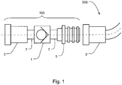
- FIG. 1 shows schematically a tube adapter 100, which in this exemplary embodiment is used for connection to a tube section 200 of a dialysis fluid tube system 300 (see Fig 2 and 3 ) is provided.
- the hose adapter 100 consists of a closure mechanism, which is designed here by way of example as a check valve 1 (hereinafter referred to as valve 1 for short) and is symbolically referred to as such, two hose connections 3, 5 and two—optionally provided— short hose sections 7 of the hose adapter 100.
- the hose adapter 100 can have other components.
- the individual components of the hose adapter 100 are firmly connected to one another, for example by means of gluing or ultrasonic welding.
- the components can also be releasably connected to one another. The latter would have the advantage that the hose adapter 100 can also be provided with hose connectors 3, 5 of different sizes at the place of use, which fit into or onto corresponding hose connectors of hose systems other than the hose system 300 shown here.
- the hose connectors 3, 5 are connected to hose couplings of the dialysis fluid hose system 300.
- the hose connection 5 is designed as a first coupling part, here as a so-called “male part” (also referred to as a socket or male connector), and the hose connection 3 as a so-called “mother part” (also referred to as a female connector).
- the female part of the coupling (hose connection 3) is identical in construction to a corresponding hose connection 3' of the known hose section 200.
- the two hose connectors 3', 5 are plugged together as a coupling, so that the dialysis fluid hose system 300 is lengthened by the exposed length of the hose adapter 100.
- the direction of flow of the dialysis fluid through the hose adapter 100 runs - based on 1 - at his intended use from right to left.
- the valve 1 of the hose adapter 100 opens - for example against a spring force - when upstream of the valve 1, i.e. in 1 to the right of it, a minimum pressure is present.
- the function of the hose adapter 100 and its valve 1 is based on 2 and 3 described in more detail.
- FIG 2 shows the dialysis fluid hose system 300 as part of a medical device 600 according to the invention (see FIG 3 ), which here is a treatment system for dialysis.
- the medical device 600 also has a blood circuit 400 (shown here as a section, see also in this regard 3 ) and also a dialyzer 11 through which the two fluids (blood and dialysis liquid) flow for mass transfer.
- Dialysis fluid tubing system 300 which can be designed as a disposable tubing system, is filled with dialysis fluid from a bag 9.
- the dialysis fluid is conveyed in the dialysis fluid tubing system 300 by means of a pump 13 , which is configured here only as an example as a roller pump.
- the dialysis fluid can flow out of the bag 9 by gravity and/or by being sucked in by the pump 13 into a heating device 14 located between the bag 9 and a heating device 14 downstream of the pump 13, ie on the pressure side of the pump 13.
- the heating device 14 shown in the figures is designed as an example of a device which has at least one heating bag 15 and heating rods or heating coils 17, which is why it is also referred to herein as a bag heater.
- the dialysis fluid is heated in the heating bag 15 .
- the dialysis liquid is helpful, possibly even necessary, for the dialysis liquid to have a positive internal pressure in the heating bag 15 compared to the ambient pressure.
- the bag wall of the heating bag 15 rests against the heating coils 17, which enables or promotes heat transfer.
- the heating bag 15 is prevented from collapsing and the heat transfer from deteriorating or being interrupted by means of a positive internal pressure.
- the valve 1 is arranged further downstream of the pump 13 and downstream of the heating device 14 .
- the valve 1 is already integrated into the hose system 300 2 therefore does not show a hose adapter 100.
- the valve 1 integrated as shown here therefore does not require any hose couplings as shown in 1 are shown.
- the valve 1 can also be used as part of a hose adapter 100 accordingly 1 be connected to the hose system 300.
- the valve 1 is arranged in the hose system 300 in such a way that when the pressure upstream of the valve 1 is too low, ie between the valve 1 and the heating device 14 or heating bag 15, the valve 1 closes. This closing also prevents a pressure that is too low downstream of valve 1 from continuing upstream of valve 1 into heating bag 15 and possibly leading to a negative internal pressure (compared to ambient pressure) or an undesirably low internal pressure. As already discussed above, a positive internal pressure in the heating bag 15 is helpful in order to ensure the optimal, the desired or the expected heat transfer.
- the opening pressure of the valve 1 is between 5 and 1000 hPa, preferably between 50 and 400 hPa, particularly preferably between 100 and 350 hPa.
- the internal pressure of the heating bag 15 must be at least this value or at least around this value must be higher than a pressure downstream of the valve so that the valve 1 opens, the flow losses occurring in the hose section between the heating bag 15 and the valve 1 are disregarded.
- the pressure upstream of valve 1 must be at least this value (between 5 and 1000 hPa, preferably between 50 and 400 hPa, particularly preferably between 100 and 350 hPa) or higher by this value in order to overcome the opening pressure of valve 1 .
- a low pressure downstream of the valve 1, and thus the dialysis liquid being "sucked empty” further upstream up to the heating bag 15, can have various causes in practice. This is facing 3 explained in more detail using a complete treatment system.
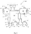
- FIG. 3 shows schematically a medical device 600 (or also referred to as a treatment system) for dialysis, in this exemplary embodiment according to the invention specifically for continuous veno-venous hemodiafiltration (combination of hemofiltration and hemodialysis), abbreviated CVV-HDF, with an extracorporeal blood circuit 400, a substitute hose system 500 and a dialysis fluid hose system 300.
- a medical device 600 or also referred to as a treatment system for dialysis
- CVV-HDF abbreviated CVV-HDF
- Blood is taken from the patient by means of an arterial connection 19 of an arterial line of the extracorporeal blood circuit 400 .
- a stopcock 21 is arranged downstream of the arterial Connection 19 .
- the arterial pressure is again measured downstream of this by means of a pressure sensor 23, and a blood pump 13' is arranged even further downstream.
- the hemofiltration pressure is measured by means of a pressure sensor 25 between the blood pump 13' and the connection of the arterial line to the dialyzer 11. Downstream of this pressure sensor 25, heparin is added to the blood at an addition point 27 to inhibit coagulation.
- the material exchange takes place with the dialysis fluid of the tube system 300, which leaves the dialyzer 11 as dialysate. This is described in more detail below.
- the blood flows downstream of the dialyzer 11 into a venous drip chamber 29 in which the venous pressure is measured by means of a pressure sensor 31 .
- a shut-off valve 33 is arranged downstream of this.
- the blood is returned to the patient's vascular system by means of a venous connection 35 .
- the substituate hose system 500 serves to substitute part of the liquid volume withdrawn during the treatment, which was withdrawn from the blood by the filtration in the dialyzer 11 .
- substituate liquid is removed from a bag 9'.
- the substituate is conveyed in the substituate hose system 500 by means of a substituate pump 13" into a heating bag 15', where it is heated and then fed into the blood circuit 400.
- the hose system 300 upstream of the dialyzer 11 has already been closed 2 explained in detail. Downstream of the dialyzer 11, the filtrate pressure is measured by a pressure sensor 37, further downstream is the dialysate conveyed together with the filtrate by a pump 13 ′′′ in a collection container 39 or discarded.
- a low pressure (relative to the ambient pressure) downstream of the valve 1, which could lead to the heating bag 15 "sucking empty” if the valve 1 were not provided, can be caused, for example, by deposits on the filter membrane of the dialyzer 11 (on the membrane side of the blood circuit 400; e.g. by beginning "clotting" of the blood). This leads to a reduction in the permeability of the filter membrane in the dialyzer and thus to an increase in the transmembrane pressure TMP (TransMembrane Pressure).
- TMP TransMembrane Pressure
- the use of filter membranes with low permeability can lead to this low pressure problem on the dialysate side of the dialyzer 11 .
- a low permeability therefore leads to a high TMP to achieve a desired or required mass transfer in the dialyzer 11.
- the use of the hose adapter 100 and / or the dialysis fluid hose system 300 can therefore be used advantageously when using filter membranes with low permeability to a high To avoid negative pressure in the heating bag 15 and thus to ensure an optimal, desired or expected heat transfer from the heater housing to the heating bag 15.
- a pressure on the dialysate side that may be too low for the needs of the heating bag is a particular problem Dialysis treatments carried out by means of continuous veno-venous hemodiafiltration (CVV-HDF), which requires high filtration flow rates and a correspondingly high pressure drop across the filter membrane, ie a high transmembrane pressure TMP.
- CVV-HDF continuous veno-venous hemodiafiltration
- the pressure reference point for the area around the filter membrane of the dialyzer 11 is in the area of the venous connection 35.
- the pressure reference point for the dialysate side is the pressure transducer 37. From there the pressure on the dialysate side of the filter membrane (in the hose system 300) can be traced by flow-related pressure drops and hydrostatic pressure differences are taken into account. If the TMP is sufficiently high, it is understandable that the pressure in the heating bag 15 may be below the ambient air pressure and thus the heating bag 15 may collapse if this is not counteracted, for example by using the hose adapter 100 or the dialysis fluid hose system 300 .
- hose adapter 200 hose section 300 dialysis fluid hose system 400 blood circulation 500
- Substituate hose system 600 Medical device 1 check valve, valve 3.3' Hose connection, female part 5 Hose connection, male part 7 hose section 9, 9' bag 11 dialyzer 13 dialysis fluid pump 13' blood pump 13" substituate pump 13′′′ dialysate pump 14 heating device 15, 15' heating bag 17 heating coils, heating rods 19 arterial connection 21 Stopcock, arterial 23 Pressure sensor for arterial pressure 25 Pressure sensor for hemofiltration pressure 27 Addition point for heparin 29 venous drip chamber 31 Pressure sensor for venous pressure 33 Stopcock, venous 35 venous connection 37 Pressure sensor for filtrate pressure 39 collection container
Landscapes
- Health & Medical Sciences (AREA)
- Heart & Thoracic Surgery (AREA)
- Animal Behavior & Ethology (AREA)
- General Health & Medical Sciences (AREA)
- Anesthesiology (AREA)
- Biomedical Technology (AREA)
- Hematology (AREA)
- Life Sciences & Earth Sciences (AREA)
- Veterinary Medicine (AREA)
- Engineering & Computer Science (AREA)
- Public Health (AREA)
- Vascular Medicine (AREA)
- Urology & Nephrology (AREA)
- Pulmonology (AREA)
- Emergency Medicine (AREA)
- External Artificial Organs (AREA)
- Infusion, Injection, And Reservoir Apparatuses (AREA)
Description
- Die vorliegende Erfindung betrifft einen Dialysierflüssigkeitsschlauch gemäß Anspruch 1 sowie eine medizinische Vorrichtung gemäß Anspruch 4.
- Aus der Praxis der Dialysebehandlung sind Vorrichtungen bekannt, mittels welcher Dialysierflüssigkeit erwärmt wird, bevor diese in den Dialysator oder Blutbehandlungsfilter, in welchem ein Stoffaustausch über eine - üblicherweise semipermeable - Membran zwischen Blut und Dialysierflüssigkeit erfolgt, eingebracht wird. Manche dieser Heizvorrichtungen erfordern ein sicheres Anliegen oder das Einhalten eines Höchstabstandes zwischen der Heizvorrichtung, welche beispielsweise die Form von Heizwendeln hat, und einem von dieser Heizvorrichtung umgebenen Behältnis, welches beispielsweise als Beutel ausgeführt ist, in welchem sich die zu erwärmende Dialysierflüssigkeit befindet. Bei einer Heizvorrichtung dieser Bauart hängt das Erzielen der gewünschten Erwärmung der Dialysierflüssigkeit davon ab, wie gut das Behältnis an der Heizvorrichtung, beispielsweise ausgeführt als Beutelheizung, anliegt (oder umgekehrt).
- Aus der
WO 98/39589 A1 - In der
WO 01/91829 A2 - Aus der
DE 103 19 197 B3 ist eine Dialyse-Anordnung mit federelastischem Ventil bekannt. - Eine Aufgabe der vorliegenden Erfindung ist es, Vorrichtungen und Verfahren vorzuschlagen zum Erzielen oder Sicherstellen eines gewünschten oder erforderlichen Anliegens der Heizvorrichtung an dem die Dialysierflüssigkeit führenden Gefäß oder Behältnis, oder zum Verhindern eines Überschreitens eines maximalen Abstandes zwischen Heizvorrichtung und Gefäß im Gebrauch oder bei der Behandlung des Patienten.
- Die erfindungsgemäße Aufgabe wird durch einen Dialysierflüsssigkeitsschlauch mit einem Schlauchadapter mit den Merkmalen des Anspruchs 1 sowie durch eine medizinische Vorrichtung mit den Merkmalen des Anspruchs 4 gelöst.
- Erfindungsgemäß wird somit ein Dialysierflüssigkeitsschlauch mit einem Schlauchadapter zum Verbinden mit wenigstens einem Schlauchabschnitt eines Dialysierflüssigkeits-Schlauchsystems vorgeschlagen. Alternativ kann der Schlauchadapter zwischen zwei Schlauchabschnitten eines Dialysierflüssigkeits-Schlauchsystems angeordnet werden oder hierzu vorgesehen und vorbereitet sein. Dabei sind sowohl der Schlauchadapter als auch der Schlauchabschnitt dafür vorgesehen und ausgestaltet, bei ihrem bestimmungsgemäßen Gebrauch von Dialysierflüssigkeit durchströmt zu werden.
- Der Schlauchadapter des Dialysierflüssigkeitsschlauchs weist erfindungsgemäß wenigstens einen Verschlussmechanismus zum reversiblen oder vorübergehenden Verschließen eines durchströmbaren Lumens des Schlauchadapters oder des hiermit verbundenen Schlauchabschnitts, und/oder eine Vorrichtung zum Erzeugen oder Verändern eines Strömungswiderstands auf.
- Das hierin offenbarte Dialysierflüssigkeits-Schlauchsystem weist wenigstens einen Schlauchadapter auf und/oder ist integral mit einem solchen Schlauchadapter hergestellt oder weist wenigstens einen Verschlussmechanismus zum Verschließen seines durchströmbaren Lumens und/oder wenigstens eine Vorrichtung zum Erzeugen oder Verändern eines Strömungswiderstands auf.
- Die medizinische Vorrichtung gemäß der vorliegenden Erfindung weist wenigstens einen erfindungsgemäßen Dialysierflüssigkeitsschlauch auf oder ist hiermit verbunden.
- Das hierin offenbarte Verwenden eines Schlauchadapters, wie hierin ebenfalls offenbart, umfasst das Verbinden des Schlauchadapters mit einem Dialysierflüssigkeits-Schlauchsystem, insbesondere mit einer oder mehreren Dialysatorkupplungen hiervon, die zur direkten Verbindung des Dialysierflüssigkeits-Schlauchsystem mit dem Dialysator oder Blutfilter ausgestaltet sind.
- Offenbart wird weiterhin ein Verfahren zum Verhindern des Auftretens eines unterhalb eines Mindestdrucks liegenden Drucks in einem Dialysierflüssigkeits-Schlauchsystem. Das Verfahren umfasst dabei entweder das Verbinden eines Schlauchadapters mit dem Dialysierflüssigkeits-Schlauchsystem oder das Anordnen eines Verschlussmechanismus zum Verschließen eines durchströmbaren Lumens des Dialysierflüssigkeits-Schlauchsystems und/oder das Anordnen einer Vorrichtung zum Erzeugen oder Verändern eines Strömungswiderstands innerhalb des Dialysierflüssigkeits-Schlauchsystems. Das Verbinden oder das Anordnen erfolgt dabei stromab einer mit dem Dialysierflüssigkeits-Schlauchsystem verbundenen Heizvorrichtung.
- Bei allen folgenden Ausführungen ist der Gebrauch des Ausdrucks "kann sein" bzw. "kann haben" usw. synonym zu "ist vorzugsweise" bzw. "hat vorzugsweise" usw. zu verstehen und soll eine erfindungsgemäße Ausführungsform erläutern.
- Vorteilhafte Weiterentwicklungen der vorliegenden Erfindung sind jeweils Gegenstand von Unteransprüchen und Ausführungsformen.
- Erfindungsgemäße Ausführungsformen können eines oder mehrere der im Folgenden genannten Merkmale aufweisen.
- In einigen Ausführungsformen der vorliegenden Erfindung ist die Veränderung des Strömungswiderstandes sprungartig, und/oder aber nicht stetig.
- In manchen Ausführungsformen der vorliegenden Erfindung stehen der Schlauchadapter und der Schlauchabschnitt des Dialysierflüssigkeits-Schlauchsystems, mit welchem er verbunden ist, in Fluidkommunikation. Der Schlauchadapter wird daher bei seinem Gebrauch von derselben Flüssigkeit und/oder stets derselben Flüssigkeitsmenge durchströmt wie der Schlauchabschnitt.
- In einigen Ausführungsformen der vorliegenden Erfindung wird der Strömungswiderstand mittels des Schlauchadapters oder eines seiner Bauteile erzeugt und/oder verändert.
- Der Schlauchadapter ist in bestimmten erfindungsgemäßen Ausführungsformen des Dialysierflüssigkeitsschlauchs vorgesehen und/oder ausgestaltet, um zu seinem Gebrauch mit wenigstens einem Schlauchabschnitt eines Dialysierflüssigkeits-Schlauchsystems verbunden zu werden.
- In bestimmten Ausführungsformen der vorliegenden Erfindung erfolgt die Veränderung des Strömungswiderstandes innerhalb des durchströmbaren Lumens des Schlauchadapters.
- In besonderen Ausführungsformen der Erfindung entspricht die Veränderung des Strömungswiderstandes einem Druckabfall oder bewirkt einen solchen.
- In einigen Ausführungsformen der vorliegenden Erfindung verhindert der Verschlussmechanismus in seinem geschlossenen Zustand ein Durchströmen des Schlauchadapters.
- In manchen Ausführungsformen der vorliegenden Erfindung verhindert der Verschlussmechanismus in seinem geschlossenen Zustand ein Eintreten von Dialysierflüssigkeit aus einer Quelle für Dialysierflüssigkeit in den Dialysator hinein.
- In einigen erfindungsgemäßen Ausführungsformen wird ein Durchströmen des Schlauchadapters infolge des Verschlussmechanismus in Abhängigkeit eines Druckzustands verhindert, der stromauf des Schlauchadapters, und dort insbesondere stromab einer Heizeinrichtung, etwa in Gestalt einer Beutelheizung, herrscht, mittels welcher die durch den Schlauchadapter geführte Dialysierflüssigkeit erwärmt worden ist.
- In manchen erfindungsgemäßen Ausführungsformen verändert oder verhindert die Vorrichtung zum Erzeugen eines Strömungswiderstandes beim bestimmungsgemäßen Gebrauch des Schlauchadapters des erfindungsgemäßen Dialysierflüssigkeitsschlauchs eine oder jegliche Fluidströmung stromab des Schlauchadapters und/oder stromauf des Schlauchadapters in Abhängigkeit eines Druckzustands, der stromauf des Schlauchadapters herrscht.
- In bestimmten Ausführungsformen der vorliegenden Erfindung dienen der Verschlussmechanismus oder die Vorrichtung zum Erzeugen eines Strömungswiderstands dazu, vorbestimmte Druckzustände stromauf des Schlauchadapters auszuschließen. Hierbei handelt es sich insbesondere um Unterdruckzustände oder Druckzustände unterhalb eines vorbestimmten Mindestdrucks.
- Ein Bestimmen oder ein Festlegen des vorbestimmten Mindestdrucks kann durch die Auswahl der einzelnen Elemente wie eines Rückschlagventils oder Druckbegrenzungsventils des Schlauchadapters erfolgen.
- Die Begriffe Rückschlagventil oder Druckbegrenzungsventil werden in einigen erfindungsgemäßen Ausführungsformen austauschbar verwendet, wo immer der Fachmann dies als technisch sinnvoll erkennt.
- In einigen erfindungsgemäßen Ausführungsformen ist der Mindestdruck ein beliebiger Unterdruck. In bestimmten erfindungsgemäßen Ausführungsformen ist der Mindestdruck ein Druck, bei welchem ein Gefäß, ein Behälter oder ein Beutel der konkret verwendeten Beutelheizung zuverlässig nicht kollabiert, wenn dieser Druck im Inneren hiervon herrscht. In gewissen erfindungsgemäßen Ausführungsformen ist der Mindestdruck ein Druck oder ein Differenzdruck von jeweils 0 hPa.
- In einigen erfindungsgemäßen Ausführungsformen bezieht sich der Mindestdruck auf einen Innendruck des Gefäßes, Behälters oder Beutels der konkret verwendeten Beutelheizung; in anderen erfindungsgemäßen Ausführungsformen bezieht sich der Mindestdruck auf einen Druck, welcher im Dialysierflüssigkeits-Schlauchsystem zwischen Heizvorrichtung und Dialysator herrscht.
- In bestimmten erfindungsgemäßen Ausführungsformen liegen der Schlauchadapter oder Komponenten hiervon stromaufwärts zum Eingang des Dialysators für Dialysierflüssigkeit.
- In einigen erfindungsgemäßen Ausführungsformen strömt in den Schlauchadapter oder Komponenten hiervon dasselbe Fluid ein wie es hieraus auch wieder ausströmt. Eine Bearbeitung des Fluids oder eine Veränderung seiner Zusammensetzung erfolgt in diesen erfindungsgemäßen Ausführungsformen innerhalb des Schlauchadapters nicht. Eine Zugabe von Infusionen oder dergleichen erfolgt in diesen Ausführungsformen ebenfalls nicht innerhalb des Schlauchadapters. Der Schlauchadapter ist hierfür nicht ausgestaltet oder vorgesehen. Der Schlauchadapter ist in bestimmten Ausführungsformen kein Wegeventil oder Mehrwegeventil.
- In bestimmten erfindungsgemäßen Ausführungsformen sind der Schlauchadapter oder Komponenten nicht ausgestaltet oder im bestimmungsgemäßen Gebrauch nicht in der Lage, das durchströmende Fluid zu verändern, beispielsweise durch, insbesondere gezieltes oder beabsichtigtes, Erwärmen.
- In manchen erfindungsgemäßen Ausführungsformen liegen der Schlauchadapter oder Komponenten hiervon nicht in einer Bypassleitung für die Pumpe.
- In gewissen Aspekten der Offenbarung weist das Dialysierflüssigkeits-Schlauchsystem keine Bypassleitung für die Pumpe auf.
- In einigen erfindungsgemäßen Ausführungsformen sind der Schlauchadapter oder seine Komponenten keine Vorrichtungen zum Begrenzen eines Drucks oder wirken nicht als solche.
- In bestimmten erfindungsgemäßen Ausführungsformen sind der Schlauchadapter oder seine Komponenten Vorrichtungen zum Sicherstellen eines Mindestdrucks oder wirken als solche.
- So ist beispielsweise ein hierin genanntes Rückschlagventil oder Druckbegrenzungsventil in einigen erfindungsgemäßen Ausführungsformen nicht vorgesehen, um einen Druck zu begrenzen, indem es bei ausreichend hohem Druck öffnet, sondern es schließt vielmehr, wenn der Druck zu niedrig ist.
- Der erfindungsgemäße Dialysierflüssigkeitsschlauch weist in bestimmten Ausführungsformen einen Schlauchabschnitt auf, welcher in eine Pumpe, beispielsweise eine okkludierende Schlauchpumpe wie etwa eine Rollenpumpe, einzulegen ist.
- In manchen erfindungsgemäßen Ausführungsformen ist der Schlauchadapter, sein Verschlussmechanismus oder seine Vorrichtung zum Erzeugen oder Verändern eines Strömungswiderstandes ein Ventil und/oder eine Drossel und/oder eine Blende, oder weist wenigstens eines der vorgenannten Elemente auf.
- Im Falle eines Ventils kann es beispielsweise ein Rückschlagventil oder Druckbegrenzungsventil mit einem definierten oder vorbestimmten Öffnungsdruck sein.
- In bestimmten erfindungsgemäßen Ausführungsformen beträgt der Öffnungsdruck des Verschlussmechanismus des Schlauchadapters mindestens 50 hPa (oder mbar) und/oder maximal 350 hPa.
- Der o. g. Mindestdruck beträgt in manchen erfindungsgemäßen Ausführungsformen 5 hPa oder liegt 5 hPa über einem stromab des Schlauchadapters oder des Verschlussmechanismus herrschenden Druck.
- In einigen erfindungsgemäßen Ausführungsformen bewirkt die Vorrichtung zum Erzeugen oder Verändern eines Strömungswiderstandes eine Veränderung derart, dass im bestimmungsgemäßen Gebrauch des Schlauchadapters über der Vorrichtung oder über dem Schlauchadapter ein Druckunterschied von mindestens 5 hPa und/oder maximal 1000 hPa, bevorzugt von mindestens 50 hPa und/oder maximal 400 hPa, besonders bevorzugt von mindestens 100 hPa und/oder 350 hPa herrscht.
- In manchen Aspekten der Offenbarung ist das Dialysierflüssigkeits-Schlauchsystem integral oder einstückig mit dem Schlauchadapter hergestellt oder fest - beispielsweise nur unter Zerstörung von diesem lösbar - mit diesem verbunden.
- In bestimmten Aspekten der Offenbarung weist das Dialysierflüssigkeits-Schlauchsystem zusätzlich einen Behälter (beispielsweise einen Sammel- oder einen Vorratsbehälter) mit Dialysierflüssigkeit auf oder ist hiermit verbunden. Dieses Fluid ist zum Durchströmen des Schlauchsystems vorgesehen.
- Zudem kann das Dialysierflüssigkeits-Schlauchsystem optional eine Pumpe aufweisen oder kann mit einer Pumpe verbunden sein, die so angeordnet ist, dass sie die Dialysierflüssigkeit im Lumen des Schlauchsystems fördern kann. Die Pumpe kann als Verdrängerpumpe, beispielsweise als Rollenpumpe ausgestaltet sein.
- Bei dem Dialysierflüssigkeits-Schlauchsystem kann es sich in einigen Aspekten der Offenbarung ungeachtet seiner Bezeichnung hierin auch um ein Schlauchsystem für andere medizinische Fluide als Dialysierflüssigkeit handeln, wo immer dies für den Fachmann erkennbar sinnvoll ist.
- Der Behälter kann als ein oder mehrere Beutel ausgestaltet sein. Solch ein Behälter findet sich beispielweise in der
US 2005/020959 A1 . - In einigen Aspekten der Offenbarung weist das Dialysierflüssigkeits-Schlauchsystem eine Heizvorrichtung zum Erwärmen der Dialysierflüssigkeit auf oder ist hiermit verbunden oder weist einen Abschnitt auf, welcher vorgesehen ist, im Gebrauch mit einer Heizvorrichtung verbunden zu werden.
- Hierbei ist die Heizvorrichtung in gewissen erfindungsgemäßen Ausführungsformen stromauf des Schlauchadapters positioniert.
- Dabei kann die Heizvorrichtung von jenem Typ sein, welcher eines gleichbleibenden, positiven, im Inneren des Behälters herrschenden Drucks bedarf, um die gewünschten Heizergebnisse zu erzielen.
- In einigen erfindungsgemäßen Ausführungsformen ist die Heizvorrichtung eine Beutelheizung.
- In manchen Aspekten der Offenbarung ist das Dialysierflüssigkeits-Schlauchsystem als Einwegprodukt ausgestaltet.
- In einigen erfindungsgemäßen Ausführungsformen ist das offenbarte Dialysierflüssigkeits-Schlauchsystem ein erfindungsgemäßer Dialysierflüssigkeitsschlauch.
- In bestimmten erfindungsgemäßen Ausführungsformen der medizinischen Vorrichtung ist diese als Blutreinigungseinrichtung ausgestaltet, beispielsweise als Dialysiervorrichtung, als Filtrationsvorrichtung, als Diafiltrationsvorrichtung oder als Dialysevorrichtung in jedem anderen, dem Fachmann bekannten Sinne.
- In gewissen erfindungsgemäßen Ausführungsformen ist die erfindungsgemäße medizinische Vorrichtung ein Behandlungssystem oder eine Behandlungsvorrichtung, mit einem extrakorporalen Blutkreislauf und/oder einem Schlauchsystem, oder sie ist hiermit verbunden.
- Die medizinische Vorrichtung ist in bestimmten erfindungsgemäßen Ausführungsformen eine Dialysiervorrichtung, die im Besonderen zur Anwendung für die kontinuierliche veno-venöse Hämodiafiltration (CVV-HDF) und/oder zur Anwendung für die Akutdialyse konfiguriert ist.
- In einigen offenbarten Ausgestaltungen des Verwendens des Schlauchadapters wird der Schlauchadapter mit dem Dialysierflüssigkeits-Schlauchsystem stromab einer Heizvorrichtung, insbesondere einer Beutelheizung, verbunden. Dabei ist die Heizvorrichtung ebenfalls mit dem Dialysierflüssigkeits-Schlauchsystem verbunden.
- In bestimmten offenbarten Ausgestaltungen des Verwendens des Schlauchadapters wird der Schlauchadapter mit den Dialysatorkupplungen des Dialysierflüssigkeits-Schlauchsystems verbunden. Der Schlauchadapter des erfindungsgemäßen Dialysierflüssigkeitsschlauchs kann hierzu entsprechend ausgestaltet sein, um beispielsweise mit dem oder den Dialysatorkupplungen per Steckverbindung, per Steck-Schraubverbindung oder dergleichen verbunden zu werden, insbesondere ohne Zuhilfenahme von Werkzeug oder weiteren Verbindungselementen.
- Unter dem Begriff Schlauch"adapter", wie hierin verwendet, ist nicht etwa einschränkend zu verstehen, dass der Schlauchadapter des erfindungsgemäßen Dialysierflüssigkeitsschlauchs etwas miteinander verbindbar machen soll, was nicht auch ohne ihn verbunden werden kann. Der Begriff umfasst vielmehr auch ein Zwischenelement oder Verbindungselement, welches verwendet werden soll, um zwei Schlauchabschnitte eines Schlauchsystems oder einen Schlauchabschnitt mit einem Dialysator in Fluidkommunikation miteinander, insbesondere unmittelbar, zu verbinden.
- In bestimmten Aspekten betrifft die Offenbarung ein Dialysierflüssigkeits-Schlauchsystem, mit wenigstens einem Schlauchadapter zum Verbinden mit wenigstens einem weiteren Schlauchabschnitt des Dialysierflüssigkeits-Schlauchsystems, wobei der Schlauchadapter wenigstens einen Verschlussmechanismus zum Verschließen seines durchströmbaren Lumens und/oder eine Vorrichtung zum Erzeugen oder Verändern eines Strömungswiderstands des Schlauchadapters, des Schlauchabschnitts oder des Dialysierflüssigkeits-Schlauchsystems aufweist, wobei das Dialysierflüssigkeits-Schlauchsystem weiterhin wenigstens einen Behälter mit Dialysierflüssigkeit, welche zum Durchströmen des Schlauchsystems vorgesehen ist, und eine Pumpe, angeordnet zum Fördern der Dialysierflüssigkeit in dem Dialysierflüssigkeits-Schlauchsystem, aufweist oder hiermit jeweils verbunden oder zur Verbindung hiermit vorgesehen ist; wobei das Dialysierflüssigkeits-Schlauchsystem weiterhin eine Heizvorrichtung zum Erwärmen der Dialysierflüssigkeit aufweist oder hiermit verbunden ist oder einen Abschnitt aufweist, welcher vorgesehen ist, im Gebrauch mit einer Heizvorrichtung verbunden zu werden; wobei die Heizvorrichtung im Gebrauch des Dialysierflüssigkeits-Schlauchsystems stromab der Pumpe angeordnet ist, wobei der Schlauchadapter stromab der Heizvorrichtung aber stromauf eines Dialysators angeordnet ist.
- Manche oder alle erfindungsgemäßen Ausführungsformen können einen, mehrere oder alle der oben und/oder im Folgenden genannten Vorteile aufweisen.
- Eine alternative Anordnung im Dialysierflüssigkeits-Schlauchsystem wäre eine Pumpe, beispielsweise eine okkludierende Pumpe (z. B. eine Rollenpumpe), stromab der Heizvorrichtung. Die Funktion des Schlauchadapters mit beispielsweise einem Rückschlagventil oder Druckbegrenzungsventil würde dann, zumindest teilweise, von der okkludierenden Pumpe übernommen werden; diese könnte das Auftreten eines Unterdrucks zwischen Heizvorrichtung und Dialysator durch ihre okkludierende Wirkung verhindern. Eine erfindungsgemäße Anordnung mit einem Dialysierflüssigkeits-Schlauchsystem, in dem die Heizvorrichtung, beispielsweise eine Beutelheizung, stromab der Pumpe angeordnet ist und der Schlauchadapter stromab der Heizvorrichtung angeordnet ist, weist die folgenden Vorteile gegenüber der genannten alternativen Lösung auf: Ein Unterdruck in der Heizvorrichtung ist nicht nur durch den Dialysator verursacht möglich (s. Beschreibung zu
Fig. 3 : ein hoher TMP im Dialysator kann verschiedene Ursachen haben), sondern auch durch ein Saugen der okkludierenden Pumpe, wie dies bei Rollenpumpen regelmäßig auftritt. Auch durch die Saugwirkung der stromab der Heizvorrichtung angeordneten, okkludierenden Pumpe kann der unerwünschte Effekt des Unterdrucks in der Heizvorrichtung auftreten. - Weiterhin werden mit der erfindungsgemäßen Anordnung mögliche Bilanzierfehler vermieden, da die Heizvorrichtung, vor allem die Beutelheizung, zwar als zusätzlicher Volumenspeicher anzusehen ist, in der Regel aber nicht im Bilanziersystem berücksichtigt ist. Eine Veränderung aufgrund Unterdrucks und Kollabierens des Gefäßes der Heizvorrichtung, vor allem der Beutelheizung, wie dies bei der o. g. alternativen Lösung auftreten kann, kann vorteilhaft mit einem Schlauchadapter des erfindungsgemäßen Dialysierflüssigkeitsschlauchs vermieden werden.
- Weiterhin kann erfindungsgemäß vorteilhaft ein Erwärmen der Dialysierflüssigkeit, ohne dass die Dialysierflüssigkeit unmittelbar gefördert wird, wie dies bei einer alternativen Anordnung möglich wäre, bei bestimmten Bicarbonat-haltigen Lösungen vermieden werden. Bei einer derartigen Erwärmung kann die Qualität der Dialysierflüssigkeit beeinträchtigt werden. Es kann zu Ausfällungen der Dialysierflüssigkeit kommen.
- Aufgrund der erfindungsgemäßen Anordnung der Pumpe stromauf der Heizvorrichtung kann eine ungewollte Abkühlung der Dialysierflüssigkeit vor dem Eintritt in den Dialysator vorteilhaft vermieden werden. Durch eine ungewollte Abkühlung könnte es zu schwer kalkulierbaren Temperaturabweichungen kommen. Diese können erfindungsgemäß vermieden werden unter Erzielen der hiermit einhergehenden Vorteile.
- Zum Erkennen eines Unterdrucks in der Heizvorrichtung, beispielsweise einer Beutelheizung, mit dem Ziel, einen solchen zu vermeiden, bedarf es bei der erfindungsgemäßen Lösung oder der erfindungsgemäßen Anordnung des Schlauchadapters bzw. seiner Komponenten zwischen der Heizvorrichtung und dem Dialysator keiner Überwachung des Filtratdrucks, also des Dialysatflüssigkeitsdrucks im Dialysator unmittelbar an der Membran, oder eines anderen Drucks auf einen geeigneten Mindestwert hin. So liegt etwa bei einer Anordnung zur kontinuierlich veno-venösen Hämodiafiltration (CW-HDF) im Wesentlichen kein relevanter Flusswiderstand zwischen Filtratdrucküberwachung und der Heizvorrichtung vor. Zwar wäre es nach einer Korrektur um einen hydrostatischen Druckunterschied möglich, einen Mindestfiltratdruck zu definieren, bei dem sichergestellt ist, dass der Druck in der Heizvorrichtung ausreichend hoch ist, um ein Kollabieren eines Beutels zu verhindern. Bei Unterschreiten dieses Mindestfiltratdrucks könnte beispielsweise die Flussrate der Pumpe gedrosselt werden. Hierzu müsste allerdings ein Steuer- oder Regelkreis aufgebaut werden, was mit Kosten und Aufwand, ferner mit Wartung, Eichung und dergleichen verbunden ist. Dies ist erfindungsgemäß nicht erforderlich.
- Ferner birgt eine solche Lösung die Gefahr, dass es in der Folge zu Fehlalarmen innerhalb des erlaubten Flussratenbereichs der Pumpen kommen könnte und die Verfügbarkeit bestimmter Behandlungsparameter eingeschränkt ist. Es könnte zu nicht interpretierbaren Warnungen (leerlaufender Heizbeutel, Bilanzwarnungen, Heizungsalarme) kommen. Durch den Einsatz des erfindungsgemäßen Schlauchadapters kann vorteilhaft auf eine Überwachung eines Mindestfiltratdrucks verzichtet werden.
- Ein weiterer Vorteil besteht darin, dass der Innendruck eines Beutels der Heizvorrichtung mittels des Schlauchadapters des erfindungsgemäßen Dialysierflüssigkeitsschlauchs um einen erforderlichen Wert zwischen 5 und 1000 hPa, bevorzugt zwischen 50 und 400 hPa, besonders bevorzugt zwischen 100 und 350 hPa angehoben werden kann. Dieser Wert wird durch die Auswahl einer handelsüblichen, oben genannten Vorrichtung, wie einem Ventil, anhand des Öffnungsdrucks in Flussrichtung einstellbar oder auswählbar.
- Die erfindungsgemäß erzielbare Erhöhung des Drucks wirkt einem unerwünschten Ausgasen der Lösung bei Kontakt mit der heißen Heizoberfläche, wie dies bei niedrigem Druck geschehen kann, vorteilhaft entgegen oder verhindert dies im Wesentlichen. Somit kann eine pH-Verschiebung durch das Ausgasen, vor allem wenn CO2 ausgegast wird, und somit das unerwünschte Ausfällen von Calciumcarbonat und anderen Verbindungen aus der strömenden Lösung vermieden werden.
- Vorteilhaft ist auch, dass der Schlauchadapter als Nachrüstteil auch erst nach Erkennen des Problems einer kollabierenden Heizvorrichtung oder Heizbeutels einsetzbar ist. Damit kann eine teure und aufwendige Integration beispielsweise eines Rückschlagventils oder Druckbegrenzungsventils in jedes einzelne der produzierten Dialysat-Schlauchsysteme vermieden werden.
- Die vorliegende Erfindung wird im Folgenden anhand der beigefügten Zeichnung, in welcher identische Bezugszeichen gleiche oder ähnliche Bauteile bezeichnen, exemplarisch erläutert. In den zum Teil stark vereinfachten Figuren gilt:
- Fig. 1
- zeigt schematisch einen Schlauchadapter eines Dialysierflüssigkeitsschlauchs in einer erfindungsgemäßen Ausführungsform mit einem Rückschlagventil und zwei Schlauchanschlüssen;
- Fig. 2
- zeigt schematisch ein Dialysierflüssigkeits-Schlauchsystem mit integriertem Rückschlagventil; und
- Fig. 3
- zeigt schematisch eine erfindungsgemäße medizinische Vorrichtung für die Dialyse mit einem extrakorporalen Blutkreislauf und einem Dialysierflüssigkeits-Schlauchsystem.
-
Fig. 1 zeigt schematisch einen Schlauchadapter 100, der in diesem Ausführungsbeispiel zur Verbindung mit einem Schlauchabschnitt 200 eines Dialysierflüssigkeits-Schlauchsystems 300 (siehe dieFig. 2 und3 ) vorgesehen ist. - Der Schlauchadapter 100 besteht in diesem Ausführungsbeispiel aus einem Verschlussmechanismus, der hier exemplarisch als Rückschlagventil 1 (im Folgenden kurz als Ventil 1 bezeichnet) ausgestaltet und als solches symbolisch bezeichnet ist, zwei Schlauchanschlüssen 3, 5 sowie zwei - optional vorgesehenen - kurzen Schlauchabschnitten 7 des Schlauchadapters 100. Der Schlauchadapter 100 kann weitere Komponenten aufweisen.
- Die einzelnen Komponenten des Schlauchadapters 100 sind in diesem Ausführungsbeispiel fest miteinander verbunden, beispielsweise mittels Kleben oder Ultraschallverschweißen. Die Komponenten können jedoch auch wieder lösbar miteinander verbunden sein. Letzteres hätte den Vorteil, dass der Schlauchadapter 100 auch noch am Ort seines Gebrauchs mit verschieden großen Schlauchanschlüssen 3, 5 vorgesehen sein kann, welche in oder auf entsprechende Schlauchanschlüsse anderer Schlauchsysteme als dem hier gezeigten Schlauchsystem 300 passen.
- Zum Verbinden des Schlauchadapters 100 werden die Schlauchanschlüsse 3, 5 mit Schlauchkupplungen des Dialysierflüssigkeits-Schlauchsystems 300 verbunden. Der Schlauchanschluss 5 ist als erstes Kupplungsteil, hier als sogenanntes "Vaterteil" (auch als Stutzen oder männlicher Verbinder bezeichnet), ausgeführt, der Schlauchanschluss 3 als sogenanntes "Mutterteil" (auch als weiblicher Verbinder bezeichnet). Das Mutterteil der Kupplung (Schlauchanschluss 3) ist in diesem Ausführungsbeispiel baugleich mit einem entsprechenden Schlauchanschluss 3' des bekannten Schlauchabschnitts 200.
- Die beiden Schlauchanschlüsse 3', 5 werden als Kupplung zusammengesteckt, so dass das Dialysierflüssigkeits-Schlauchsystem 300 hierdurch um die freiliegende Länge des Schlauchadapters 100 verlängert wird.
- Die Strömungsrichtung der Dialysierflüssigkeit durch den Schlauchadapter 100 verläuft - bezogen auf
Fig. 1 - bei dessen bestimmungsgemäßen Gebrauch von rechts nach links. Das Ventil 1 des Schlauchadapters 100 öffnet sich - beispielsweise gegen eine Federkraft - dann, wenn stromauf des Ventils 1, also inFig. 1 rechts davon, ein Mindestdruck anliegt. - Die Funktion des Schlauchadapters 100 bzw. seines Ventils 1 wird anhand von
Fig. 2 und3 näher beschrieben. -
Fig. 2 zeigt das Dialysierflüssigkeits-Schlauchsystem 300 als Teil einer erfindungsgemäßen medizinischen Vorrichtung 600 (sieheFig. 3 ), welche hier ein Behandlungssystem für eine Dialyse ist. Die medizinische Vorrichtung 600 weist weiterhin einen Blutkreislauf 400 (hier als Ausschnitt dargestellt, siehe auch hierzuFig. 3 ) auf, ferner einen Dialysator 11, der von beiden Fluiden (Blut und Dialysierflüssigkeit) zum Stoffaustausch durchströmt wird. - Das Dialysierflüssigkeits-Schlauchsystem 300, das als Einweg-Schlauchsystem ("Disposable") ausgeführt sein kann, wird von einer Dialysierflüssigkeit aus einem Beutel 9 befüllt. Die Dialysierflüssigkeit wird mittels einer hier nur exemplarisch als Rollenpumpe ausgestalteten Pumpe 13 im Dialysierflüssigkeits-Schlauchsystem 300 gefördert. Dabei kann die Dialysierflüssigkeit aus dem Beutel 9 mittels Schwerkraft und/oder durch Ansaugen mittels der Pumpe 13 in eine zwischen dem Beutel 9 und einer stromab der Pumpe 13, also auf der Druckseite der Pumpe 13, gelegene Heizvorrichtung 14 fließen. Die in den Figuren gezeigte Heizvorrichtung 14 ist exemplarisch als eine Vorrichtung ausgestaltet, welche wenigstens einen Heizbeutel 15 und Heizstäbe oder Heizwendeln 17 aufweist, weshalb sie hierin auch als Beutelheizung bezeichnet wird. Im Heizbeutel 15 wird die Dialysierflüssigkeit erwärmt. Zur Gewährleistung des Wärmeübergangs von der Heizvorrichtung 14 oder den Heizwendeln 17 auf den Heizbeutel 15 ist es hilfreich, ggf. gar notwendig, dass in dem Heizbeutel 15 ein positiver Innendruck der Dialysierflüssigkeit gegenüber dem Umgebungsdruck herrscht. Auf diese Weise legt sich die Beutelwand des Heizbeutels 15 an die Heizwendeln 17 an, was den Wärmeübergang ermöglicht oder begünstigt. Anders ausgedrückt wird mittels eines positiven Innendrucks ein Kollabieren des Heizbeutels 15 und eine Verschlechterung oder Unterbrechung des Wärmeübergangs verhindert.
- Weiter stromab der Pumpe 13 und stromab der Heizvorrichtung 14 ist das Ventil 1 angeordnet. In diesem Ausführungsbeispiel ist das Ventil 1 bereits in das Schlauchsystem 300 integriert,
Fig. 2 zeigt daher keinen Schlauchadapter 100. Das wie hier integrierte Ventil 1 bedarf daher keiner Schlauchkupplungen, wie sie inFig. 1 dargestellt sind. Alternativ kann das Ventil 1 jedoch auch als Teil eines Schlauchadapters 100 entsprechendFig. 1 an das Schlauchsystem 300 angeschlossen werden. - Das Ventil 1 ist derart in dem Schlauchsystem 300 angeordnet, dass bei einem zu niedrigen Druck stromauf des Ventils 1, also zwischen Ventil 1 und Heizvorrichtung 14 oder Heizbeutel 15, das Ventil 1 schließt. Mit diesem Schließen wird auch verhindert, dass sich ein stromab des Ventils 1 herrschender zu niedriger Druck stromaufwärts des Ventils 1 bis in den Heizbeutel 15 fortsetzt und dort möglicherweise zu einem negativen Innendruck (gegenüber dem Umgebungsdruck) oder einem unerwünscht niedrigen Innendruck führt. Wie weiter oben bereits diskutiert wurde, ist ein positiver Innendruck im Heizbeutel 15 hilfreich, um den optimalen, den gewünschten oder den erwarteten Wärmeübergang zu gewährleisten.
- Der Öffnungsdruck des Ventils 1 liegt in manchen erfindungsgemäßen Ausführungsformen zwischen 5 und 1000 hPa, bevorzugt zwischen 50 und 400 hPa, besonders bevorzugt zwischen 100 und 350 hPa. Dies bedeutet, dass der Innendruck des Heizbeutels 15 mindestens diesen Wert betragen muss oder mindestens um diesen Wert höher sein muss als ein Druck stromab des Ventils, damit das Ventil 1 öffnet, lässt man die in dem Schlauchabschnitt zwischen Heizbeutel 15 und Ventil 1 auftretenden Strömungsverluste außer Betracht. Anders ausgedrückt muss der Druck stromauf des Ventils 1 mindestens diesen Wert (zwischen 5 und 1000 hPa, bevorzugt zwischen 50 und 400 hPa, besonders bevorzugt zwischen 100 und 350 hPa) betragen oder um diesen Wert höher liegen, um den Öffnungsdruck des Ventils 1 zu überwinden.
- Ein niedriger Druck stromab des Ventils 1, und damit ein "Leersaugen" der Dialysierflüssigkeit weiter stromauf bis hin zum Heizbeutel 15, kann in der Praxis verschiedene Ursachen haben. Dies wird mit Blick auf
Fig. 3 anhand eines vollständigen Behandlungssystems näher erläutert. -
Fig. 3 zeigt schematisch eine medizinische Vorrichtung 600 (oder auch als Behandlungssystem bezeichnet) für die Dialyse, in diesem erfindungsgemäßen Ausführungsbeispiel speziell für die kontinuierliche veno-venöse Hämodiafiltration (Kombination von Hämofiltration und Hämodialyse), abgekürzt CVV-HDF, mit einem extrakorporalen Blutkreislauf 400, einem Substituat-Schlauchsystem 500 und einem Dialysierflüssigkeits-Schlauchsystem 300. - Dem Patienten wird mittels eines arteriellen Anschlusses 19 einer arteriellen Leitung des extrakorporalen Blutkreislaufs 400 Blut entnommen. Stromab des arteriellen Anschlusses 19 ist ein Absperrhahn 21 angeordnet. Wiederum stromab hiervon wird der arterielle Druck mittels eines Drucksensors 23 gemessen, noch weiter stromab ist eine Blutpumpe 13' angeordnet. Zwischen der Blutpumpe 13' und dem Anschluss der arteriellen Leitung an den Dialysator 11 wird der Hämofiltrationsdruck mittels eines Drucksensors 25 gemessen. Stromab dieses Drucksensors 25 wird dem Blut an einer Zugabestelle 27 Heparin zur Gerinnungshemmung zugegeben.
- Im Dialysator 11 findet der Stoffaustausch mit der Dialysierflüssigkeit des Schlauchsystems 300, welches den Dialysator 11 als Dialysat verlässt, statt. Dies wird weiter unten näher beschrieben.
- Stromab des Dialysators 11 fließt das Blut in eine venöse Tropfkammer 29, in der mittels eines Drucksensors 31 der venöse Druck gemessen wird. Stromab hiervon ist ein Absperrhahn 33 angeordnet. Das Blut wird mittels eines venösen Anschlusses 35 in das Gefäßsystem des Patienten zurückgeführt.
- Das Substituat-Schlauchsystem 500 dient dazu, dem Patienten einen Teil des bei der Behandlung entzogenen Flüssigkeitsvolumens, welches dem Blut durch die Filtration im Dialysator 11 entzogen wurde, zu substituieren. Hierzu wird Substituat-Flüssigkeit aus einem Beutel 9' entnommen. Das Substituat wird im Substituat-Schlauchsystem 500 mittels einer Substituatpumpe 13" in einen Heizbeutel 15' gefördert, dort erwärmt und anschließend dem Blutkreislauf 400 zugeführt.
- Das Schlauchsystem 300 stromauf des Dialysators 11 wurde bereits zu
Fig. 2 eingehend erläutert. Stromab des Dialysators 11 wird der Filtratdruck mittels eines Drucksensors 37 gemessen, weiter stromab wird das Dialysat gemeinsam mit dem Filtrat mittels einer Pumpe 13‴ in einen Auffangbehälter 39 gefördert oder verworfen. - Nachfolgend werden in der Praxis auftretende Ursachen eines niedrigen Drucks stromab des Ventils 1 diskutiert.
- Ein niedriger Druck (gegenüber dem Umgebungsdruck) stromab des Ventils 1, welcher zu einem "Leersaugen" des Heizbeutels 15 führen könnte, wäre nicht das Ventil 1 vorgesehen, kann beispielsweise durch Ablagerungen auf der Filtermembran des Dialysators 11 (auf der Membranseite des Blutkreislauf 400; z. B. durch beginnendes "Clotting" des Blutes) bedingt sein. Dies führt zu einer Verringerung der Permeabilität der Filtermembran im Dialysator und damit zu einem Anstieg des Transmembrandrucks TMP (TransMembrane Pressure).
- Unabhängig von diesem Phänomen kann die Verwendung von Filtermembranen mit geringer Permeabilität (es treten die gleichen Effekte wie bei Ablagerungen auf der Membran auf) zu diesem Problem des niedrigen Drucks auf der Dialysatseite des Dialysators 11 führen. Eine geringe Permeabilität führt daher zu einem hohen TMP zum Erreichen eines gewünschten bzw. geforderten Stoffaustauschs im Dialysator 11. Die Verwendung des Schlauchadapters 100 und/oder des Dialysierflüssigkeits-Schlauchsystems 300 kann daher bei Verwendung von Filtermembranen mit geringer Permeabilität vorteilhaft dazu genutzt werden, einen hohen Unterdruck im Heizbeutel 15 zu vermeiden und damit einen optimalen, gewünschten oder den erwarteten Wärmeübergang vom Heizungsgehäuse auf den Heizbeutel 15 zu gewährleisten.
- Ein möglicherweise für die Belange des Heizbeutels zu niedriger Druck auf der Dialysatseite tritt besonders bei Dialyse-Behandlungen auf, die mittels der kontinuierlichen veno-venösen Hämodiafiltration (CVV-HDF) durchgeführt werden, was hohe Filtrationsflussraten und ein entsprechend hohes Druckgefälle über die Filtermembran, d.h. einen hohen Transmembrandruck TMP, erfordert.
- Der Druckbezugspunkt für den Bereich um die Filtermembran des Dialysators 11 liegt im Bereich des venösen Anschlusses 35. Der Druckbezugspunkt für die Dialysatseite ist der Druckaufnehmer 37. Von dort kann der Druck auf die Dialysatseite der Filtermembran (im Schlauchsystem 300) rückverfolgt werden, indem strömungsbedingte Druckabfälle und hydrostatische Druckunterschiede berücksichtigt werden. Bei hinreichend hohem TMP ist so nachvollziehbar, dass es zu einem Druck im Heizungsbeutel 15 unterhalb des Umgebungsluftdrucks und damit zu einem Kollabieren des Heizbeutels 15 kommen kann, wenn diesem nicht, beispielsweise durch das Verwenden des Schlauchadapters 100 oder des Dialysierflüssigkeits-Schlauchsystems 300, entgegengewirkt wird.
Bezugszeichenliste Bezugszeichen Beschreibung 100 Schlauchadapter 200 Schlauchabschnitt 300 Dialysierflüssigkeits-Schlauchsystem 400 Blutkreislauf 500 Substituat-Schlauchsystem 600 Medizinische Vorrichtung 1 Rückschlagventil, Ventil 3,3' Schlauchanschluss, Mutterteil 5 Schlauchanschluss, Vaterteil 7 Schlauchabschnitt 9, 9' Beutel 11 Dialysator 13 Dialysierflüssigkeitspumpe 13' Blutpumpe 13" Substituatpumpe 13‴ Dialysatpumpe 14 Heizvorrichtung 15, 15' Heizbeutel 17 Heizwendel, Heizstäbe 19 arterieller Anschluss 21 Absperrhahn, arteriell 23 Drucksensor für arteriellen Druck 25 Drucksensor für Hämofiltrationsdruck 27 Zugabestelle für Heparin 29 venöse Tropfkammer 31 Drucksensor für venösen Druck 33 Absperrhahn, venös 35 venöser Anschluss 37 Drucksensor für Filtratdruck 39 Auffangbehälter
Claims (5)
- Dialysierflüssigkeitsschlauch (300), aufweisend wenigstens- einen Schlauchadapter (100), verbunden mit wenigstens einem Schlauchabschnitt des Dialysierflüssigkeitsschlauchs (300),wobei der Schlauchadapter (100) wenigstens einen Verschlussmechanismus zum Verschließen seines durchströmbaren Lumens aufweist,wobei der Verschlussmechanismus ein Rückschlagventil mit einem vorbestimmten Öffnungsdruck ist,wobei der Öffnungsdruck des Rückschlagventils mindestens 5 hPa und/oder maximal 1000 hPa beträgt,- einen Abschnitt, welcher vorgesehen ist, um im Gebrauch mit einer Beutelheizung verbunden zu werden,- einen Schlauchabschnitt, welcher im Gebrauch in eine Pumpe (13) zum Fördern der Dialysierflüssigkeit innerhalb des Dialysierflüssigkeitsschlauchs (300) einzulegen ist,wobei der Abschnitt zum Verbinden mit der Beutelheizung stromab des Schlauchabschnitts zum Einlegen in die Pumpe (13) angeordnet ist, undwobei der Schlauchadapter (100) stromab des Abschnitts zum Verbinden mit der Beutelheizung angeordnet ist.
- Dialysierflüssigkeitsschlauch (300) nach Anspruch 1, wobei der Öffnungsdruck des Rückschlagventils mindestens 50 hPa und/oder maximal 400 hPa, bevorzugt mindestens 100 hPa und/oder maximal 350 hPa beträgt.
- Dialysierflüssigkeitsschlauch (300) nach einem der Ansprüche 1 bis 2, wobei der Schlauchadapter integral mit dem Dialysierflüssigkeitsschlauch (300) hergestellt ist.
- Medizinische Vorrichtung (600), aufweisend wenigstens einen Dialysierflüssigkeitsschlauch (300) nach einem der Ansprüche 1 bis 3 oder hiermit verbunden.
- Medizinische Vorrichtung (600) nach Anspruch 4, ausgestaltet als Blutreinigungseinrichtung oder Dialysevorrichtung.
Applications Claiming Priority (3)
| Application Number | Priority Date | Filing Date | Title |
|---|---|---|---|
| US201261609387P | 2012-03-12 | 2012-03-12 | |
| DE102012004673A DE102012004673A1 (de) | 2012-03-12 | 2012-03-12 | Schlauchadapter zum Beeinflussen des Drucks innerhalb eines Schlauchabschnitts während einer medizinischen Behandlung |
| PCT/EP2013/000714 WO2013135365A2 (de) | 2012-03-12 | 2013-03-11 | Schlauchadapter zum beeinflussen des drucks innerhalb eines schlauchabschnitts während einer medizinischen behandlung |
Publications (2)
| Publication Number | Publication Date |
|---|---|
| EP2825250A2 EP2825250A2 (de) | 2015-01-21 |
| EP2825250B1 true EP2825250B1 (de) | 2023-01-18 |
Family
ID=49029335
Family Applications (1)
| Application Number | Title | Priority Date | Filing Date |
|---|---|---|---|
| EP13709773.9A Active EP2825250B1 (de) | 2012-03-12 | 2013-03-11 | Schlauchadapter zum beeinflussen des drucks innerhalb eines schlauchabschnitts während einer medizinischen behandlung |
Country Status (15)
| Country | Link |
|---|---|
| US (1) | US9629993B2 (de) |
| EP (1) | EP2825250B1 (de) |
| JP (1) | JP6284493B2 (de) |
| KR (1) | KR102185003B1 (de) |
| CN (1) | CN104220126B (de) |
| AU (1) | AU2013231643B2 (de) |
| BR (1) | BR112014022470B1 (de) |
| CA (1) | CA2865221C (de) |
| DE (1) | DE102012004673A1 (de) |
| EA (1) | EA033951B1 (de) |
| ES (1) | ES2942257T3 (de) |
| IN (1) | IN2014DN08384A (de) |
| MX (1) | MX352169B (de) |
| PL (1) | PL2825250T3 (de) |
| WO (1) | WO2013135365A2 (de) |
Families Citing this family (15)
| Publication number | Priority date | Publication date | Assignee | Title |
|---|---|---|---|---|
| US9861733B2 (en) | 2012-03-23 | 2018-01-09 | Nxstage Medical Inc. | Peritoneal dialysis systems, devices, and methods |
| EP3524288B1 (de) | 2011-03-23 | 2024-11-06 | NxStage Medical Inc. | Peritonealdialysesysteme |
| DE102013014751A1 (de) * | 2013-09-06 | 2015-03-12 | Fresenius Medical Care Deutschland Gmbh | Verfahren zum Beeinflussen des Drucks innerhalb eines Heizbeutels während einer medizinischen Behandlung und medizinische Vorrichtung |
| DE102014013419A1 (de) * | 2014-09-10 | 2016-03-10 | Fresenius Medical Care Deutschland Gmbh | Vorrichtung umfassend einen mehrlumigen Schlauch |
| US10485483B1 (en) * | 2016-10-17 | 2019-11-26 | Srs Medical Systems, Llc | Diagnostic drainage catheter assembly and methods |
| EP3348291B1 (de) | 2017-01-12 | 2019-12-04 | Gambro Lundia AB | Extrakorporale blutbehandlungsvorrichtung und verfahren zur überprüfung der verbindung eines weichen beutels in einer extrakorporalen blutbehandlungsvorrichtung |
| EP3641850B1 (de) | 2017-06-24 | 2024-10-09 | NxStage Medical Inc. | Systeme zur herstellung von peritonealdialyseflüssigkeit |
| US11207454B2 (en) | 2018-02-28 | 2021-12-28 | Nxstage Medical, Inc. | Fluid preparation and treatment devices methods and systems |
| EP3714919A1 (de) * | 2019-03-29 | 2020-09-30 | Fresenius Medical Care Deutschland GmbH | Neuinfusionsschlauchsystem, verpackung und verfahren |
| EP4110453B1 (de) * | 2020-02-24 | 2025-07-30 | Siemens Healthcare Diagnostics Inc. | Verbindungssystem mit lösbarer konturdichtung für ein fluidsystem |
| DE102020111867A1 (de) | 2020-04-30 | 2021-11-04 | Fresenius Medical Care Deutschland Gmbh | Hämodialysevorrichtung mit Gasaustauscher |
| WO2022085032A1 (en) * | 2020-10-22 | 2022-04-28 | Wuppuluru Gowrishankar | System and method for contactless replacement of medical tubing connections |
| US20240252727A1 (en) * | 2021-05-21 | 2024-08-01 | Physidia | Dialysis machine and corresponding method |
| EP4194023A1 (de) * | 2021-12-09 | 2023-06-14 | Gambro Lundia AB | Wegwerfbarer satz und extrakorporale blutbehandlungsvorrichtung zur verhinderung der entgasung in einer infusionsfluidleitung |
| DE102024105078A1 (de) | 2024-02-22 | 2025-08-28 | Fresenius Medical Care Deutschland Gmbh | Verfahren zum Überprüfen eines Bestückungszustandes einer Blutbehandlungsvorrichtung, und Vorrichtungen |
Family Cites Families (21)
| Publication number | Priority date | Publication date | Assignee | Title |
|---|---|---|---|---|
| EP0563324B1 (de) * | 1990-12-21 | 1999-05-06 | Abbott Laboratories | Mischvorrichtung für die infusion von medikamenten |
| US5431626A (en) * | 1993-03-03 | 1995-07-11 | Deka Products Limited Partnership | Liquid pumping mechanisms for peritoneal dialysis systems employing fluid pressure |
| DE4313636C1 (de) * | 1993-04-26 | 1994-10-13 | Fresenius Ag | Konnektorsystem zum Verbinden von Flüssigkeitsbehältern |
| SE510512C2 (sv) * | 1994-08-23 | 1999-05-31 | Gambro Lundia Ab | Förfarande och anslutningsenhet för steril överföring av en lösning |
| US5591344A (en) * | 1995-02-13 | 1997-01-07 | Aksys, Ltd. | Hot water disinfection of dialysis machines, including the extracorporeal circuit thereof |
| DE19650664C1 (de) * | 1996-12-06 | 1998-01-02 | Fresenius Ag | Medizinische Vorrichtung zum Zuführen von Flüssigkeiten |
| US6044859A (en) | 1997-03-03 | 2000-04-04 | Filtertek Inc | Valve apparatus and method |
| SE9901165D0 (sv) * | 1999-03-30 | 1999-03-30 | Gambro Lundia Ab | Method, apparatus and components of dialysis systems |
| JP3561432B2 (ja) * | 1999-04-14 | 2004-09-02 | 有限会社谷田部ビニール工業 | 医療用加温バッグおよびこれに用いる逆止弁構造 |
| IL136512A0 (en) * | 2000-06-01 | 2001-06-14 | Medivice Systems Ltd | Intravenous infusion administration set |
| DE10055283B4 (de) * | 2000-11-08 | 2004-07-15 | Fresenius Kabi Deutschland Gmbh | Adapter für eine PEG-Sonde |
| US20050010158A1 (en) | 2001-05-24 | 2005-01-13 | Brugger James M. | Drop-in blood treatment cartridge with filter |
| DE10319197B3 (de) | 2003-04-29 | 2004-07-29 | S-Med Medizintechnik Gmbh | Dialyse-Anordnung mit federelastischem Ventil |
| JP4646666B2 (ja) * | 2005-03-28 | 2011-03-09 | 旭化成クラレメディカル株式会社 | 医療用具用継手 |
| US8202241B2 (en) * | 2007-02-15 | 2012-06-19 | Asahi Kasei Medical Co., Ltd. | Blood purification system |
| KR101911864B1 (ko) * | 2007-02-27 | 2018-10-26 | 데카 프로덕츠 리미티드 파트너쉽 | 혈액투석 시스템 |
| DE102007018362A1 (de) * | 2007-04-18 | 2008-10-30 | Fresenius Medical Care Deutschland Gmbh | Verfahren zur Vorbereitung einer Behandlungsmaschine und Behandlungsmaschine |
| US8512553B2 (en) * | 2007-07-05 | 2013-08-20 | Baxter International Inc. | Extracorporeal dialysis ready peritoneal dialysis machine |
| US7809254B2 (en) * | 2007-07-05 | 2010-10-05 | Baxter International Inc. | Dialysis fluid heating using pressure and vacuum |
| US8597505B2 (en) * | 2007-09-13 | 2013-12-03 | Fresenius Medical Care Holdings, Inc. | Portable dialysis machine |
| CN201668779U (zh) * | 2010-05-20 | 2010-12-15 | 重庆山外山科技有限公司 | 血液透析系统 |
-
2012
- 2012-03-12 DE DE102012004673A patent/DE102012004673A1/de not_active Ceased
-
2013
- 2013-03-11 WO PCT/EP2013/000714 patent/WO2013135365A2/de not_active Ceased
- 2013-03-11 PL PL13709773.9T patent/PL2825250T3/pl unknown
- 2013-03-11 KR KR1020147028475A patent/KR102185003B1/ko active Active
- 2013-03-11 BR BR112014022470-6A patent/BR112014022470B1/pt active IP Right Grant
- 2013-03-11 US US13/792,389 patent/US9629993B2/en active Active
- 2013-03-11 JP JP2014561314A patent/JP6284493B2/ja active Active
- 2013-03-11 CA CA2865221A patent/CA2865221C/en active Active
- 2013-03-11 EP EP13709773.9A patent/EP2825250B1/de active Active
- 2013-03-11 ES ES13709773T patent/ES2942257T3/es active Active
- 2013-03-11 EA EA201400994A patent/EA033951B1/ru not_active IP Right Cessation
- 2013-03-11 MX MX2014010876A patent/MX352169B/es active IP Right Grant
- 2013-03-11 AU AU2013231643A patent/AU2013231643B2/en active Active
- 2013-03-11 CN CN201380014140.8A patent/CN104220126B/zh active Active
-
2014
- 2014-10-08 IN IN8384DEN2014 patent/IN2014DN08384A/en unknown
Also Published As
| Publication number | Publication date |
|---|---|
| EA033951B1 (ru) | 2019-12-12 |
| EP2825250A2 (de) | 2015-01-21 |
| WO2013135365A2 (de) | 2013-09-19 |
| CN104220126A (zh) | 2014-12-17 |
| ES2942257T3 (es) | 2023-05-31 |
| BR112014022470B1 (pt) | 2021-05-04 |
| EA201400994A1 (ru) | 2015-04-30 |
| KR20140133609A (ko) | 2014-11-19 |
| IN2014DN08384A (de) | 2015-05-08 |
| DE102012004673A1 (de) | 2013-09-12 |
| CA2865221C (en) | 2020-05-05 |
| CA2865221A1 (en) | 2013-09-19 |
| JP2015509795A (ja) | 2015-04-02 |
| HK1205968A1 (en) | 2015-12-31 |
| JP6284493B2 (ja) | 2018-02-28 |
| KR102185003B1 (ko) | 2020-12-02 |
| WO2013135365A3 (de) | 2014-04-03 |
| CN104220126B (zh) | 2017-08-22 |
| MX352169B (es) | 2017-11-13 |
| MX2014010876A (es) | 2014-10-15 |
| US20130237903A1 (en) | 2013-09-12 |
| AU2013231643A1 (en) | 2014-10-23 |
| US9629993B2 (en) | 2017-04-25 |
| PL2825250T3 (pl) | 2023-05-15 |
| AU2013231643B2 (en) | 2017-03-09 |
Similar Documents
| Publication | Publication Date | Title |
|---|---|---|
| EP2825250B1 (de) | Schlauchadapter zum beeinflussen des drucks innerhalb eines schlauchabschnitts während einer medizinischen behandlung | |
| EP3041525B1 (de) | Medizinische vorrichtung mit einer steuervorrichtung zum beeinflussen des drucks innerhalb eines heizbeutels während einer medizinischen behandlung | |
| EP2106266B1 (de) | Verfahren zum Primen eines Blutschlauchsatzes | |
| DE4240681C2 (de) | Vorrichtung zur Hämodialyse ohne Antikoagulation | |
| DE3333362C2 (de) | Peritonealdialysegerät | |
| EP3689392B1 (de) | Behandlungsvorrichtung zum entfernen von blut aus einem extrakorporalen blutkreislauf | |
| EP2467178B1 (de) | Schlauchset für eine vorrichtung zur blutbehandlung und vorrichtung zur blutbehandlung mit einem schlauchset | |
| DE102014000678A1 (de) | Vorrichtung und Verfahren zur Regelung und Vorgabe der Pumprate von Blutpumpen | |
| EP3445418B1 (de) | Medizinische behandlungsvorrichtung und verfahren zur überwachung einer medizinischen behandlungsvorrichtung | |
| DE102011110472A1 (de) | Verfahren sowie Vorrichtungen zum Ablösen von Gasansammlungen von einem Gerinnselfänger eines extrakorporalen Blutkreislaufs | |
| DE102020126226A1 (de) | Disposable und System mit einem Port | |
| EP2954911A2 (de) | Dialysemaschinen-integrierte substituatpumpe | |
| EP3024511B1 (de) | Extrakorporale blutbehandlungsvorrichtung | |
| EP2291210A1 (de) | Universell anwendbares optimiertes perfusionssystem | |
| EP3191152B1 (de) | Vorrichtung umfassend einen mehrlumigen schlauch | |
| WO2023104884A1 (de) | Blutbehandlungsvorrichtung mit gekoppelter blutpumpe und drucklufteinrichtung | |
| EP2988661B1 (de) | Steuereinheit und verfahren zur bestimmung eines drucks in einem blutgefäss, insbesondere in einer arteriovenösen fistel | |
| EP3996768B1 (de) | Dialysegerät mit drei bilanzkammern | |
| DE102024123176A1 (de) | Medizinische Behandlungsvorrichtung | |
| DE102020133686A1 (de) | Konnektor für Dialysatorport, Dialysator, Verfahren und Blutbehandlungsvorrichtung | |
| EP4294477A1 (de) | Vorrichtung und verfahren zur diskonnektion | |
| EP3941548A1 (de) | Extrakorporale blutbehandlungsmaschine mit poka yoke für druckaufnehmer |
Legal Events
| Date | Code | Title | Description |
|---|---|---|---|
| PUAI | Public reference made under article 153(3) epc to a published international application that has entered the european phase |
Free format text: ORIGINAL CODE: 0009012 |
|
| 17P | Request for examination filed |
Effective date: 20141013 |
|
| AK | Designated contracting states |
Kind code of ref document: A2 Designated state(s): AL AT BE BG CH CY CZ DE DK EE ES FI FR GB GR HR HU IE IS IT LI LT LU LV MC MK MT NL NO PL PT RO RS SE SI SK SM TR |
|
| AX | Request for extension of the european patent |
Extension state: BA ME |
|
| DAX | Request for extension of the european patent (deleted) | ||
| REG | Reference to a national code |
Ref country code: HK Ref legal event code: DE Ref document number: 1205968 Country of ref document: HK |
|
| STAA | Information on the status of an ep patent application or granted ep patent |
Free format text: STATUS: EXAMINATION IS IN PROGRESS |
|
| 17Q | First examination report despatched |
Effective date: 20171222 |
|
| GRAP | Despatch of communication of intention to grant a patent |
Free format text: ORIGINAL CODE: EPIDOSNIGR1 |
|
| STAA | Information on the status of an ep patent application or granted ep patent |
Free format text: STATUS: GRANT OF PATENT IS INTENDED |
|
| INTG | Intention to grant announced |
Effective date: 20220317 |
|
| GRAJ | Information related to disapproval of communication of intention to grant by the applicant or resumption of examination proceedings by the epo deleted |
Free format text: ORIGINAL CODE: EPIDOSDIGR1 |
|
| STAA | Information on the status of an ep patent application or granted ep patent |
Free format text: STATUS: EXAMINATION IS IN PROGRESS |
|
| GRAS | Grant fee paid |
Free format text: ORIGINAL CODE: EPIDOSNIGR3 |
|
| STAA | Information on the status of an ep patent application or granted ep patent |
Free format text: STATUS: GRANT OF PATENT IS INTENDED |
|
| GRAP | Despatch of communication of intention to grant a patent |
Free format text: ORIGINAL CODE: EPIDOSNIGR1 |
|
| INTC | Intention to grant announced (deleted) | ||
| INTG | Intention to grant announced |
Effective date: 20220816 |
|
| GRAA | (expected) grant |
Free format text: ORIGINAL CODE: 0009210 |
|
| STAA | Information on the status of an ep patent application or granted ep patent |
Free format text: STATUS: THE PATENT HAS BEEN GRANTED |
|
| AK | Designated contracting states |
Kind code of ref document: B1 Designated state(s): AL AT BE BG CH CY CZ DE DK EE ES FI FR GB GR HR HU IE IS IT LI LT LU LV MC MK MT NL NO PL PT RO RS SE SI SK SM TR |
|
| REG | Reference to a national code |
Ref country code: GB Ref legal event code: FG4D Free format text: NOT ENGLISH |
|
| REG | Reference to a national code |
Ref country code: CH Ref legal event code: EP |
|
| REG | Reference to a national code |
Ref country code: DE Ref legal event code: R096 Ref document number: 502013016329 Country of ref document: DE |
|
| REG | Reference to a national code |
Ref country code: AT Ref legal event code: REF Ref document number: 1544341 Country of ref document: AT Kind code of ref document: T Effective date: 20230215 Ref country code: IE Ref legal event code: FG4D Free format text: LANGUAGE OF EP DOCUMENT: GERMAN |
|
| REG | Reference to a national code |
Ref country code: LT Ref legal event code: MG9D |
|
| REG | Reference to a national code |
Ref country code: NL Ref legal event code: MP Effective date: 20230118 |
|
| REG | Reference to a national code |
Ref country code: ES Ref legal event code: FG2A Ref document number: 2942257 Country of ref document: ES Kind code of ref document: T3 Effective date: 20230531 |
|
| PG25 | Lapsed in a contracting state [announced via postgrant information from national office to epo] |
Ref country code: NL Free format text: LAPSE BECAUSE OF FAILURE TO SUBMIT A TRANSLATION OF THE DESCRIPTION OR TO PAY THE FEE WITHIN THE PRESCRIBED TIME-LIMIT Effective date: 20230118 |
|
| P01 | Opt-out of the competence of the unified patent court (upc) registered |
Effective date: 20230602 |
|
| PG25 | Lapsed in a contracting state [announced via postgrant information from national office to epo] |
Ref country code: RS Free format text: LAPSE BECAUSE OF FAILURE TO SUBMIT A TRANSLATION OF THE DESCRIPTION OR TO PAY THE FEE WITHIN THE PRESCRIBED TIME-LIMIT Effective date: 20230118 Ref country code: PT Free format text: LAPSE BECAUSE OF FAILURE TO SUBMIT A TRANSLATION OF THE DESCRIPTION OR TO PAY THE FEE WITHIN THE PRESCRIBED TIME-LIMIT Effective date: 20230518 Ref country code: NO Free format text: LAPSE BECAUSE OF FAILURE TO SUBMIT A TRANSLATION OF THE DESCRIPTION OR TO PAY THE FEE WITHIN THE PRESCRIBED TIME-LIMIT Effective date: 20230418 Ref country code: LV Free format text: LAPSE BECAUSE OF FAILURE TO SUBMIT A TRANSLATION OF THE DESCRIPTION OR TO PAY THE FEE WITHIN THE PRESCRIBED TIME-LIMIT Effective date: 20230118 Ref country code: LT Free format text: LAPSE BECAUSE OF FAILURE TO SUBMIT A TRANSLATION OF THE DESCRIPTION OR TO PAY THE FEE WITHIN THE PRESCRIBED TIME-LIMIT Effective date: 20230118 Ref country code: HR Free format text: LAPSE BECAUSE OF FAILURE TO SUBMIT A TRANSLATION OF THE DESCRIPTION OR TO PAY THE FEE WITHIN THE PRESCRIBED TIME-LIMIT Effective date: 20230118 |
|
| PG25 | Lapsed in a contracting state [announced via postgrant information from national office to epo] |
Ref country code: SE Free format text: LAPSE BECAUSE OF FAILURE TO SUBMIT A TRANSLATION OF THE DESCRIPTION OR TO PAY THE FEE WITHIN THE PRESCRIBED TIME-LIMIT Effective date: 20230118 Ref country code: IS Free format text: LAPSE BECAUSE OF FAILURE TO SUBMIT A TRANSLATION OF THE DESCRIPTION OR TO PAY THE FEE WITHIN THE PRESCRIBED TIME-LIMIT Effective date: 20230518 Ref country code: GR Free format text: LAPSE BECAUSE OF FAILURE TO SUBMIT A TRANSLATION OF THE DESCRIPTION OR TO PAY THE FEE WITHIN THE PRESCRIBED TIME-LIMIT Effective date: 20230419 Ref country code: FI Free format text: LAPSE BECAUSE OF FAILURE TO SUBMIT A TRANSLATION OF THE DESCRIPTION OR TO PAY THE FEE WITHIN THE PRESCRIBED TIME-LIMIT Effective date: 20230118 |
|
| REG | Reference to a national code |
Ref country code: DE Ref legal event code: R097 Ref document number: 502013016329 Country of ref document: DE |
|
| PG25 | Lapsed in a contracting state [announced via postgrant information from national office to epo] |
Ref country code: SM Free format text: LAPSE BECAUSE OF FAILURE TO SUBMIT A TRANSLATION OF THE DESCRIPTION OR TO PAY THE FEE WITHIN THE PRESCRIBED TIME-LIMIT Effective date: 20230118 Ref country code: RO Free format text: LAPSE BECAUSE OF FAILURE TO SUBMIT A TRANSLATION OF THE DESCRIPTION OR TO PAY THE FEE WITHIN THE PRESCRIBED TIME-LIMIT Effective date: 20230118 Ref country code: MC Free format text: LAPSE BECAUSE OF FAILURE TO SUBMIT A TRANSLATION OF THE DESCRIPTION OR TO PAY THE FEE WITHIN THE PRESCRIBED TIME-LIMIT Effective date: 20230118 Ref country code: EE Free format text: LAPSE BECAUSE OF FAILURE TO SUBMIT A TRANSLATION OF THE DESCRIPTION OR TO PAY THE FEE WITHIN THE PRESCRIBED TIME-LIMIT Effective date: 20230118 Ref country code: DK Free format text: LAPSE BECAUSE OF FAILURE TO SUBMIT A TRANSLATION OF THE DESCRIPTION OR TO PAY THE FEE WITHIN THE PRESCRIBED TIME-LIMIT Effective date: 20230118 Ref country code: CZ Free format text: LAPSE BECAUSE OF FAILURE TO SUBMIT A TRANSLATION OF THE DESCRIPTION OR TO PAY THE FEE WITHIN THE PRESCRIBED TIME-LIMIT Effective date: 20230118 |
|
| REG | Reference to a national code |
Ref country code: CH Ref legal event code: PL |
|
| PLBE | No opposition filed within time limit |
Free format text: ORIGINAL CODE: 0009261 |
|
| STAA | Information on the status of an ep patent application or granted ep patent |
Free format text: STATUS: NO OPPOSITION FILED WITHIN TIME LIMIT |
|
| PG25 | Lapsed in a contracting state [announced via postgrant information from national office to epo] |
Ref country code: SK Free format text: LAPSE BECAUSE OF FAILURE TO SUBMIT A TRANSLATION OF THE DESCRIPTION OR TO PAY THE FEE WITHIN THE PRESCRIBED TIME-LIMIT Effective date: 20230118 |
|
| REG | Reference to a national code |
Ref country code: BE Ref legal event code: MM Effective date: 20230331 |
|
| 26N | No opposition filed |
Effective date: 20231019 |
|
| PG25 | Lapsed in a contracting state [announced via postgrant information from national office to epo] |
Ref country code: LU Free format text: LAPSE BECAUSE OF NON-PAYMENT OF DUE FEES Effective date: 20230311 |
|
| REG | Reference to a national code |
Ref country code: IE Ref legal event code: MM4A |
|
| PG25 | Lapsed in a contracting state [announced via postgrant information from national office to epo] |
Ref country code: SI Free format text: LAPSE BECAUSE OF FAILURE TO SUBMIT A TRANSLATION OF THE DESCRIPTION OR TO PAY THE FEE WITHIN THE PRESCRIBED TIME-LIMIT Effective date: 20230118 Ref country code: LI Free format text: LAPSE BECAUSE OF NON-PAYMENT OF DUE FEES Effective date: 20230331 Ref country code: IE Free format text: LAPSE BECAUSE OF NON-PAYMENT OF DUE FEES Effective date: 20230311 Ref country code: CH Free format text: LAPSE BECAUSE OF NON-PAYMENT OF DUE FEES Effective date: 20230331 |
|
| PG25 | Lapsed in a contracting state [announced via postgrant information from national office to epo] |
Ref country code: BE Free format text: LAPSE BECAUSE OF NON-PAYMENT OF DUE FEES Effective date: 20230331 |
|
| REG | Reference to a national code |
Ref country code: AT Ref legal event code: MM01 Ref document number: 1544341 Country of ref document: AT Kind code of ref document: T Effective date: 20230311 |
|
| PG25 | Lapsed in a contracting state [announced via postgrant information from national office to epo] |
Ref country code: AT Free format text: LAPSE BECAUSE OF NON-PAYMENT OF DUE FEES Effective date: 20230311 |
|
| PG25 | Lapsed in a contracting state [announced via postgrant information from national office to epo] |
Ref country code: AT Free format text: LAPSE BECAUSE OF NON-PAYMENT OF DUE FEES Effective date: 20230311 |
|
| PG25 | Lapsed in a contracting state [announced via postgrant information from national office to epo] |
Ref country code: BG Free format text: LAPSE BECAUSE OF FAILURE TO SUBMIT A TRANSLATION OF THE DESCRIPTION OR TO PAY THE FEE WITHIN THE PRESCRIBED TIME-LIMIT Effective date: 20230118 |
|
| PG25 | Lapsed in a contracting state [announced via postgrant information from national office to epo] |
Ref country code: BG Free format text: LAPSE BECAUSE OF FAILURE TO SUBMIT A TRANSLATION OF THE DESCRIPTION OR TO PAY THE FEE WITHIN THE PRESCRIBED TIME-LIMIT Effective date: 20230118 |
|
| PGFP | Annual fee paid to national office [announced via postgrant information from national office to epo] |
Ref country code: DE Payment date: 20250218 Year of fee payment: 13 |
|
| PGFP | Annual fee paid to national office [announced via postgrant information from national office to epo] |
Ref country code: FR Payment date: 20250219 Year of fee payment: 13 Ref country code: PL Payment date: 20250221 Year of fee payment: 13 |
|
| PGFP | Annual fee paid to national office [announced via postgrant information from national office to epo] |
Ref country code: IT Payment date: 20250218 Year of fee payment: 13 Ref country code: GB Payment date: 20250221 Year of fee payment: 13 |
|
| PGFP | Annual fee paid to national office [announced via postgrant information from national office to epo] |
Ref country code: TR Payment date: 20250226 Year of fee payment: 13 |
|
| PGFP | Annual fee paid to national office [announced via postgrant information from national office to epo] |
Ref country code: ES Payment date: 20250401 Year of fee payment: 13 |
|
| PG25 | Lapsed in a contracting state [announced via postgrant information from national office to epo] |
Ref country code: CY Free format text: LAPSE BECAUSE OF FAILURE TO SUBMIT A TRANSLATION OF THE DESCRIPTION OR TO PAY THE FEE WITHIN THE PRESCRIBED TIME-LIMIT; INVALID AB INITIO Effective date: 20130311 |
|
| PG25 | Lapsed in a contracting state [announced via postgrant information from national office to epo] |
Ref country code: HU Free format text: LAPSE BECAUSE OF FAILURE TO SUBMIT A TRANSLATION OF THE DESCRIPTION OR TO PAY THE FEE WITHIN THE PRESCRIBED TIME-LIMIT; INVALID AB INITIO Effective date: 20130311 |