EP2823799A1 - Dispositif et procédé d'insertion de feuilles dans des presses à comprimés - Google Patents
Dispositif et procédé d'insertion de feuilles dans des presses à comprimés Download PDFInfo
- Publication number
- EP2823799A1 EP2823799A1 EP20130176062 EP13176062A EP2823799A1 EP 2823799 A1 EP2823799 A1 EP 2823799A1 EP 20130176062 EP20130176062 EP 20130176062 EP 13176062 A EP13176062 A EP 13176062A EP 2823799 A1 EP2823799 A1 EP 2823799A1
- Authority
- EP
- European Patent Office
- Prior art keywords
- module
- films
- carriers
- carrier
- tablet press
- Prior art date
- Legal status (The legal status is an assumption and is not a legal conclusion. Google has not performed a legal analysis and makes no representation as to the accuracy of the status listed.)
- Granted
Links
- 238000000034 method Methods 0.000 title claims abstract description 35
- 238000012546 transfer Methods 0.000 claims abstract description 52
- 239000000969 carrier Substances 0.000 claims description 82
- 238000003860 storage Methods 0.000 claims description 9
- 238000003780 insertion Methods 0.000 claims description 5
- 230000037431 insertion Effects 0.000 claims description 5
- 239000011159 matrix material Substances 0.000 claims description 5
- 230000001953 sensory effect Effects 0.000 claims description 4
- 239000003937 drug carrier Substances 0.000 claims description 2
- 125000006850 spacer group Chemical group 0.000 claims description 2
- 230000001360 synchronised effect Effects 0.000 claims 1
- 239000010408 film Substances 0.000 description 170
- 239000000843 powder Substances 0.000 description 28
- 239000011888 foil Substances 0.000 description 15
- 238000003825 pressing Methods 0.000 description 12
- 239000010410 layer Substances 0.000 description 11
- 238000004519 manufacturing process Methods 0.000 description 10
- 239000000463 material Substances 0.000 description 7
- 239000013590 bulk material Substances 0.000 description 5
- 230000003287 optical effect Effects 0.000 description 5
- 239000004033 plastic Substances 0.000 description 5
- 229920003023 plastic Polymers 0.000 description 5
- 239000002245 particle Substances 0.000 description 4
- 238000013461 design Methods 0.000 description 3
- 239000007787 solid Substances 0.000 description 3
- 239000000853 adhesive Substances 0.000 description 2
- 230000003993 interaction Effects 0.000 description 2
- 230000000873 masking effect Effects 0.000 description 2
- 238000000465 moulding Methods 0.000 description 2
- 238000012545 processing Methods 0.000 description 2
- 239000010935 stainless steel Substances 0.000 description 2
- 229910001220 stainless steel Inorganic materials 0.000 description 2
- 239000013543 active substance Substances 0.000 description 1
- 239000000956 alloy Substances 0.000 description 1
- 229910045601 alloy Inorganic materials 0.000 description 1
- 239000002131 composite material Substances 0.000 description 1
- 238000010924 continuous production Methods 0.000 description 1
- 239000013039 cover film Substances 0.000 description 1
- 230000007812 deficiency Effects 0.000 description 1
- 230000002950 deficient Effects 0.000 description 1
- 230000001419 dependent effect Effects 0.000 description 1
- 238000004090 dissolution Methods 0.000 description 1
- 239000000945 filler Substances 0.000 description 1
- 210000001035 gastrointestinal tract Anatomy 0.000 description 1
- 238000000338 in vitro Methods 0.000 description 1
- 238000001727 in vivo Methods 0.000 description 1
- 239000007788 liquid Substances 0.000 description 1
- 239000002184 metal Substances 0.000 description 1
- 229910052751 metal Inorganic materials 0.000 description 1
- 150000002739 metals Chemical class 0.000 description 1
- 239000000203 mixture Substances 0.000 description 1
- 239000002991 molded plastic Substances 0.000 description 1
- 239000005445 natural material Substances 0.000 description 1
- 239000011236 particulate material Substances 0.000 description 1
- 230000001766 physiological effect Effects 0.000 description 1
- 230000001681 protective effect Effects 0.000 description 1
- 238000004080 punching Methods 0.000 description 1
- 239000002356 single layer Substances 0.000 description 1
- 239000002195 soluble material Substances 0.000 description 1
- 210000002784 stomach Anatomy 0.000 description 1
- 230000007704 transition Effects 0.000 description 1
- 238000012795 verification Methods 0.000 description 1
Images


Classifications
-
- B—PERFORMING OPERATIONS; TRANSPORTING
- B30—PRESSES
- B30B—PRESSES IN GENERAL
- B30B11/00—Presses specially adapted for forming shaped articles from material in particulate or plastic state, e.g. briquetting presses, tabletting presses
- B30B11/02—Presses specially adapted for forming shaped articles from material in particulate or plastic state, e.g. briquetting presses, tabletting presses using a ram exerting pressure on the material in a moulding space
- B30B11/08—Presses specially adapted for forming shaped articles from material in particulate or plastic state, e.g. briquetting presses, tabletting presses using a ram exerting pressure on the material in a moulding space co-operating with moulds carried by a turntable
-
- B—PERFORMING OPERATIONS; TRANSPORTING
- B30—PRESSES
- B30B—PRESSES IN GENERAL
- B30B15/00—Details of, or accessories for, presses; Auxiliary measures in connection with pressing
- B30B15/30—Feeding material to presses
-
- A—HUMAN NECESSITIES
- A61—MEDICAL OR VETERINARY SCIENCE; HYGIENE
- A61J—CONTAINERS SPECIALLY ADAPTED FOR MEDICAL OR PHARMACEUTICAL PURPOSES; DEVICES OR METHODS SPECIALLY ADAPTED FOR BRINGING PHARMACEUTICAL PRODUCTS INTO PARTICULAR PHYSICAL OR ADMINISTERING FORMS; DEVICES FOR ADMINISTERING FOOD OR MEDICINES ORALLY; BABY COMFORTERS; DEVICES FOR RECEIVING SPITTLE
- A61J3/00—Devices or methods specially adapted for bringing pharmaceutical products into particular physical or administering forms
- A61J3/10—Devices or methods specially adapted for bringing pharmaceutical products into particular physical or administering forms into the form of compressed tablets
Definitions
- the invention relates to a transfer and positioning device and to a method for placing a film in the die of a tablet press.
- rotary tablet presses are described for example for the pharmaceutical industry, with which normal single-layer tablets, multi-layer tablets and / or Mantelkerntabletten can be produced.
- the production of Mantelkerntabletten is very expensive, since in a tablet, a second tablet - a so-called core - is.
- the tablet presses which are suitable for the production of coated tablets, have in the jacket core design on the pitch circle of the die plate of a tablet press not only one but in particular two filling devices for powder. These two powder filling devices contain the powder with which the core of a mantle core tablet is encased.
- a core module located between the two powder filling the tablet press a core module, via which the cores to be coated are introduced individually into the die of a rotary tablet press.
- the cores to be coated are fed to the core module in the usual way as bulk material.
- the actual pressing process for the production of coated tablets proceeds in such a way that initially powder is introduced via the first powder filling device in the die of the tablet press and then the core to be coated is introduced by means of core module into the die.
- the second Pulver Stahls By means of the second Pulveryogll réelles the inserted core is covered with powder, the powder is finally compacted by the pressing process, thereby creating a solid shell, the so-called coat around the core.
- each mantle core tablet is monitored. If no core or only parts of a core have been inserted, the pressing force drops below the lower control limit, the tablet is recognized as defective and automatically sorted out via a pneumatic switch. In this way it can be ensured that each wrapper core tablet actually has a core.
- a disadvantage of the devices and methods in the prior art is that only cores can be sheathed, which can be supplied as bulk material to the core module. Shaped bodies that stick to one another, are very light, limp and / or can not be supplied as individual shaped bodies to the core module in the sense of a bulk material due to their shape or nature, can not be used as a core for a sheath core tablet.
- the object of the present invention is therefore to provide a device and a method which do not have the disadvantages and deficiencies of the prior art and offer a solution to coat particularly flexible moldings that were previously inaccessible as a core for a Mantelkerntablette.
- FIG. 5 an exemplary embodiment of the device is shown.
- the FIG. 5 also shows how the modules 1, 2 and 3 interact.
- the device is in particular computer-controlled and comprises suitable drives in order to ensure the functionality of the modules, so that the device and the method of the present invention are in particular automatically controllable.
- Module 1 comprises in particular a storage magazine for films, wherein the films are individually packaged. It has proved to be advantageous if module 1 is suitable for providing the films to be coated in such a way that the films can be taken over individually.
- Module 1 comprises a storage magazine in which the films are not provided as bulk material, as in the prior art, but individually packaged. This can be done, for example, over a long carrier tape comprising molded troughs in which the films are located.
- the troughs of the carrier tape are covered in particular for storage and transport purposes with a protective film.
- the carrier tape can be rolled up, for example.
- Module 1 preferably comprises a receptacle for a plurality of rolls with carrier tapes. Further, the carrier tape can be manually or automatically transported with module 1, unrolled and the films are unpacked, so that the films are removed from the wells individually. The removal takes place, in particular, with module 2. It is advantageous that this type of provision of films by means of module 1 can take place automatically and optionally discontinuously or continuously, in order to thereby enable a reproducible provision of films.
- module 2 comprises the following units which are selected from the group transfer units, receiving elements, conveyor belts, deflecting wheels, guide rails, spacers, stoppers, control sensors, inlet wheels, discharge wheels and / or switches.
- deflecting wheels comprises in particular inlet wheels and / or outlet wheels.
- An exemplary embodiment of module 2 is in FIG. 2 shown. These FIG. 2 also shows the interaction of the transfer units, conveyor belts, control sensors, inlet wheels, sprockets and switches.
- the module 2 essentially comprises the transfer unit, which as a receiving element comprises a "pick and place" unit, which is in particular equipped with vacuum heads to suck the films.
- the acquisition unit of module 2 as a receiving element a transfer head with up to 50 vacuum heads, preferably with up to 30 vacuum heads, more preferably with up to 20 vacuum heads and most preferably comprising up to 10 vacuum heads. Of course, for example, 5 vacuum heads or 1 vacuum head can be used.
- module 2 comprises two flexible conveyor belts with deflection wheels.
- the conveyor belts are flexible and can accommodate, for example, about 300 carriers. With the carriers, the films are transported on the conveyor belt to module 3 (takeover and pressfit module).
- the guide rails of module 2 are designed so that the carriers can be kept in the track during their transport. Automatic stoppers prevent uncontrolled damming of the carriers.
- four optical control sensors are involved in the control of module 2.
- the module 2 comprises a capacity for 5000 carriers, preferably for 2500 carriers, more preferably for 1000 carriers, and most preferably for 300 carriers.
- module 2 For example, only 50 carriers can be used. It is also preferred that the carriers include locating holes for centering the foils. It was surprising that by the interaction of the different units of module 2, a transport can be realized that runs reproducibly. Due to the particularly automatic process, a controlled process can be made available to make sensitive moldings of an automatic further processing accessible.
- the module 2 is particularly suitable due to the modular design and the flexible and variable in length conveyor belt to customize the required throughput. Just the variability and flexibility of the present invention and especially when transporting ein theder, sensitive films to realize a high number of pieces was completely surprising.
- module 3 comprises vacuum heads, movable arms, at least two control cams, compressed air connections and / or vacuum connections, the vacuum heads being lowerable and immersed in dies of the tablet press.
- the vacuum heads of module 3 are designed as transfer / transfer heads, which take over as part of module 3 films of module 2 and represent a removal device.
- the vacuum heads constitute as part of module 3 a loading unit, which the of Module 2 inserted films inserted into the matrices of the tablet press or transfers.
- the rotational speed of module 3 is variable and adjustable synchronously with the rotor speed of the tablet machine.
- Module 3 adopts the films of module 2.
- Module 3 is able to suck the films from the carriers through the vacuum heads.
- FIG. 3 an exemplary embodiment of the module 3 is shown.
- the FIG. 2 shows how the modules 2 and 3 interact.
- the invention can be used in a variety of ways and can be tailored to the most diverse requirements individually, for example with regard to throughput and speed.
- the films are inserted substantially centrally in the matrices. It is preferred if the films are an information carrier, a release layer and / or a drug carrier, wherein the films are light, pliable, yielding, flexible, rigid and / or rechargeable. It is also preferred that the films have all conceivable shapes and are, for example, round, angular, oval or asymmetrical. In particular, the films have a diameter of from 1 mm to 20 mm, preferably from 1 mm to 15 mm, more preferably from 1 mm to 10 mm and most preferably from 1 mm to 5 mm.
- the films may have a thickness of from 0.1 mm to 10 mm, preferably from 0.1 mm to 5 mm, more preferably from 0.1 mm to 1 mm and most preferably from 0.1 mm to 0.5 mm. It was completely surprising that the present invention opens up a wide range of possibilities for making a wide variety of shaped bodies accessible to tabletting which hitherto could not be processed in or into a tablet.
- the films comprise in particular plastics as material, but also natural substances, composites, metals or else mixtures or alloys are for example included as material of the present invention.
- the films can represent a one- or multi-component system.
- the films are, for example, homogeneous in their nature, may have a smooth or rough surface and / or consist of particulate material. It is also preferred if the films consist of a soluble material which dissolves in association with liquids, for example in the stomach or intestinal tract.
- the films may also contain a pharmaceutically active agent which is released, for example, during dissolution or disintegration of the film.
- Both in insoluble films and in the soluble films smallest solid particles can be embedded. These solid particles may have a size of 0.5-50 mm 3 . It is further preferred if the particles have a diameter which is less than 20 mm, preferably less than 10 mm, more preferably less than 5 mm and most preferably less than 1 mm.
- the particles may be, for example, electronic chips, which are in particular biodegradable.
- films in particular comprise chips which monitor, regulate and / or control physiological effects.
- the films can also be used as in vivo or in vitro markers for control and verification purposes.
- the films which can be processed with the present invention are very light in comparison to the cores used in the production of normal mantle core tablets, very small in size, unstable, elastically deformable and / or electrostatically chargeable. It is advantageous that also films can be processed, which stick to each other at elevated humidity. That foils can be coated which are freely movable in the room with minimal air circulation in the room and / or which stick to all the objects they touch with the slightest electrostatic charge. It was completely surprising that with the present invention such diverse shaped bodies can be introduced into the matrix of a tablet press. It is precisely this multiplicity of differently configured films in size, shape, texture, weight and appearance that constitutes a significant advantage over the prior art.
- films in which a delivery excretes as bulk material can be processed, for example, with the present invention. It was completely surprising that it was possible to dispense with vibrators or centrifugal conveyors when feeding the films to the tablet press and when introducing them into a die.
- Module 1 brings the foils into the transfer position, where the foils of Module 2 are taken over.
- the films are delivered in a molded plastic carrier tape on a carrier tape spool, comparable to a film spool.
- This carrier tape has shaped, for example deep-drawn, hollows, in each of which a film is located.
- the carrier tape made of plastic, for example, provided with a self-adhesive masking tape, so that the slides can not fall out.
- One side of the carrier tape is perforated like a film strip for unwinding and positioning the rolled-up carrier tape.
- the module 1 comprises, for example, a device which can accommodate up to 1000 carrier tape reels, preferably up to 100 carrier tape reels and most preferably up to 10 carrier tape reels with carrier tapes.
- the carrier tape is threaded to provide the films, for example, in a so-called feeder, which automatically replaces the self-adhesive masking tape, wound and motor, for example, every 1.5 seconds brings a film in the takeover position.
- a so-called feeder which automatically replaces the self-adhesive masking tape, wound and motor, for example, every 1.5 seconds brings a film in the takeover position.
- ten feeders in particular discontinuously, for example clocked, ten films can be provided every 1 second for collection by module 2.
- the films are delivered by means of one or more film trays.
- the films are then punched out of the film tray, for example, either individually or in several pieces directly before being provided, brought into the transfer position after punching by means of module 1 and made available for collection by module 2.
- the process steps of providing the films by means of module 1 and / or taking over the films by means of module 2 are discontinuous.
- the films for example, after they have been provided by means of module 1, are taken over by module 2 clocked.
- a continuous provision of the films and a continuous acquisition of the films by module 2 is covered by the present invention.
- the module 2 comprises for taking over the films of module 1, a suitable receiving element. This receiving element is, for example, a "pick and place" unit, which takes over the films provided with module 1.
- the "Pick and Place” unit of module 2 comprises an extendable arm and a transfer head with, for example, 10 suction cups.
- the arm of the "pick and place” unit is brought into a position so that the transfer head of the "pick and place” unit with the 10 suction heads is located directly above the foils provided with module 1.
- the films are provided in particular by means of 10 feeders arranged in series, so that 10 films can be taken over at the same time. By vacuum, the films are sucked by the suction heads of the "Pick and Place” unit.
- the diameter of the suction heads at the contact surface to the film corresponds approximately to the diameter of the films.
- the transfer head of the "pick and place" unit of module 2 lifts the films out of the carrier tape and brings the films to, for example, ten waiting carriers, which are located on a conveyor belt 1.
- At least one conveyor belt with at least two webs is used and the receiving element of module 2 alternately feeds the carriers on web 1 and web 2 with films.
- the films are transferred from the suction heads of the "pick and place" unit (receiving element) of the module 2 to the carrier by the films are deposited in the receiving bores of the carrier.
- the films are centered on the carriers.
- the mounting holes of the carriers are slightly conical, so that a further centering of the films is ensured.
- 10 carriers are loaded simultaneously with films. After loading the carriers, which are located on track 1, the carriers loaded with films are preferably controlled by sensors. This monitors whether all carriers are actually loaded with a foil. As soon as the 10 carriers are loaded, a stopper opens the web 1 and the 10 carriers are moved in the direction of module 3 by the permanently running flexible conveyor belt 1.
- the carriers of both tracks are brought together on a web and in the absence of loading the carrier with a film, the carriers are pushed by means of a second conveyor belt, which the empty carrier to reload the carrier with slides.
- the carriers are made of stainless steel, so that they are stable with the necessary weight on the conveyor belt.
- the inserts on the upper part of the carrier are made of white FDA-approved plastic.
- the foils, for example, are colored dark, so that there is a clear contrast to the white inserts. This makes it easier for the sensors to reliably detect the inserted foils. If slides are missing in individual carriers, there is a message about this and you can check whether the fault is due to the feeders of module 1 or to individual suction heads of the "Pick and Place" unit of module 2.
- the conveyor belt 1 is arranged so that the carrier of the two webs 1 and 2 are dammed and mutually released on a web on the conveyor belt side opposite to the "pick and place” unit. As a result, the clocked transport of the carrier goes into a continuous transport.
- module 2 comprises an inlet wheel, which adjusts a distance between the carriers and continuously transfers the carrier with the films to module 3. It is advantageous that the module 3, in contrast to the feeders of module 1 and the "pick and place" unit of module 2 works continuously.
- Module 3 in particular represents a film press-in module, which synchronously and continuously running with the rotor of the tablet press.
- An advantage is that module 2 realizes a balance between the clocked operation of the film acquisition of module 1 and the continuous operation in the film transfer by module 3 to the tablet press.
- the films are taken clocked by the receiving element of the module 2 and inserted by module 3 in a continuous operation in the dies of the tablet press.
- the films are guided centrally from the takeover by the receiving element of module 2 until they are placed in the matrices of the tablet press by means of carriers or transported by centric positive engagement on the vacuum heads.
- a further conveyor belt 2 is present.
- the two conveyor belts for example, connected to each other via a switch.
- the switch to the conveyor belt 2 is another optical sensor which controls the presence of a film on the carrier. If no film is present in the receiving bore of the carrier, the carrier is pushed by conveyor belt 1 onto conveyor belt 2 and automatically transported back to the loading station via a second switch.
- the charging station is the station where the films are transferred to the carriers by means of a "pick and place" unit. Thus, only loaded carriers are continuously forwarded to module 3, the so-called takeover and press-in station.
- the module 2 comprises an inlet wheel and an outlet wheel. Through the recesses in the inlet wheel, the carriers are brought to the stitch spacing of the transfer / transfer heads of module 3. Between the inlet wheel and the outlet wheel, the transfer / transfer heads of module 3 take over the transport of the carriers. As with the "Pick and Place" unit of module 2, module 3 also includes suction cups. By means of a control cam drive the suction heads down and take the slides from the carriers by means of vacuum. It is preferred that the films are centered in the acquisition by module 3. It is further preferred that empty carriers are supplied to the module 2, after removal of the films by module 3 or by suction, by means of at least one outlet wheel and are provided for a new loading with films.
- sensors check the removal of the films from the carriers by module 3. It is also preferred that a film is sucked off, which was not removed by module 3 and is still in the carrier after passing through module 3. Also in module 3, the contact surface of the suction cups corresponds to the diameter of the films.
- the vacuum heads (suction heads) of module 3 After the vacuum heads (suction heads) of module 3 have removed the films from the carriers, the vacuum heads (suction heads) with the films are driven upwards again. The empty carriers are transferred to the discharge wheel and fed to the conveyor belt 1.
- an optical sensor that checks whether a film has remained in the carrier and possibly has not been taken over by the suction heads of module 3. If this is the case, the foil remaining in the carrier is automatically sucked off with a nozzle. This prevents a carrier with a film in the charging station and there could be equipped with an additional film.
- the vacuum heads of module 3 in the position opposite the takeover by module 2 on the pitch circle of the matrix of the tablet press move in synchronism with the die position.
- the movable arms move to the die plate of the tablet press (rotary press).
- the rotational speed of module 3 is controlled synchronously by the rotor speed of the tablet press.
- the heads are pressed down so that the vacuum heads dive with the films in the die holes and so the discs can be pressed in particular in the press material of a first layer of powder.
- the vacuum is switched off and a subsequent slight blast of compressed air ensures that the films do not stick to the suction head.
- the vacuum heads leave the die holes, are returned to the old pitch circle via the control cam, the vacuum lines are blown open with a powerful blast of compressed air, and then take over the next foils from the carriers. In this way, the films are individually placed in the dies of the tablet press.
- the tablet press comprises two powder filling devices and two pressing stations. It is an advantage if one pressing station is located to the left and right of module 3. With the pressing station 1, the powder (pressing material) of the first layer, which has been placed in the matrix, is pressed lightly in order to vent the material and to obtain a smooth surface. Subsequently, the film via the module 3 is automatically and continuously introduced into the die. It is preferred that the films are inserted centrally into the dies of the tablet press.
- the turntable of the module 3 operates synchronously with the operating speed of the rotor of the tablet press, so that the films are continuously inserted into the matrices.
- the films are deposited on the first compressed powder layer.
- the film With the second pressing station, the film is lightly pressed and pressed into the first powder layer.
- the first layer with the inserted foil is simultaneously pushed into the filling position for the second powder layer. This creates a filling space for the second powder layer (cover layer).
- the resulting cavity is then filled with the second filling shoe and, for example, the same pressing material as in the presentation of the first powder layer in the die.
- the press material is pressed by means of the upper and lower punches and with the help of the pre-press and the main press to a coated tablet.
- the coated tablet is ejected and passed with the tablet scraper over the chute from the tablet press.
- FIG. 1 shows a plan view of module 1 (11), in particular a feeder (15), in which, for example, 10 shaped carrier tapes for the films are arranged side by side so that at the same time 10 films of module 2 (12) can be adopted.
- the module 1 (11) comprises a storage space for receiving the carrier tapes. From this storage space, the carrier tapes can be brought with the films manually or automatically via an opening in the position where the films of module 2 (12) are taken. When unrolling the carrier tape, the cover film is pulled off in particular over the molded, for example deep-drawn, hollows in which the films to be coated are located. In this way, the films are accessible for acquisition by module 2 (12) and thus provided.
- module 1 (11) variable in the Height is and can be docked to the module 2 (12) and in this way a direct contact between the supply unit of module 1 (11) and the "pick and place” unit (16) of module 2 (12) can be produced.
- FIG. 2 shows a plan view of module 2 (12), which for example a "pick and place” unit (16), conveyor belt 1 (17) with two tracks (18a, 19), inlet wheel (22), outlet wheel (23), optical control sensors (20), conveyor belt 2 (21) and switches (24a, 24b).
- the module 2 (12) comprises a capacity for, for example, 300 carriers (28).
- the films of module 1 (11) are taken, placed on carriers (28) and transported on the carriers (28) by means of the conveyor belt 1 (17) to the module 3 (13).
- a transfer arm is extended for transfer of the films by module 2 (12) and preferably placed directly over the provided films.
- the transfer arm preferably comprises, for example, 10 suction heads with which 10 films can be sucked in at the same time by means of a vacuum.
- the transfer arm is part of the "Pick and Place" unit (16).
- the transfer arm is extendable and rotatable by, for example, 360 °, preferably 180 ° horizontally.
- takeover arm can be extended vertically and variably adjusted.
- the carriers (28) were sensory checked before deployment (20), whether the carriers (28) are not already loaded with a film. Only empty carriers (28) are provided for loading with foils. After loading, we open a stopper and loaded with films carrier (28) are moved on the permanently moving conveyor belt 1 (17). In FIG. 2 the direction of travel of the conveyor belt 1 (17) and thus the carrier (28) is provided in particular in the counterclockwise direction.
- the module 2 (12) has, in particular, guide rails to ensure that the carriers (28) can not leave the conveyor belt 1 or 2 (17, 21) during transport.
- guide rails on the flexible conveyor belt (17, 21) it is also possible, for example, that the carriers (28) can follow directional changes of the conveyor belt 1 or 2 (17, 21) during transport.
- the conveyor belt 1 (17) is arranged so that on the way to the module 3 (13) two horizontal changes of direction are performed by 90 °.
- FIG. 2 shows, in the position of the switch 24b the transition from conveyor belt 1 (17) to conveyor belt 2 (21). This represents the position where unloaded carriers (28) detected by sensory control (20) are sorted out and fed via conveyor belt 2 (21) to a loading position of the pick and place unit (16).
- the two webs 18a, 19 of conveyor belt 1 (17) are brought together prior to the carrier transfer to module 3 (13) to web 18b.
- the carriers (28) before handing over to the module 3 (13) dammed and then via the inlet wheel (22) a defined distance between the loaded carriers (28) is set. It is thereby achieved that the carriers (28) have exactly the distance which is necessary for the transfer / transfer heads (25) of module 3 (13) to be able to take over the films from the carriers (28).
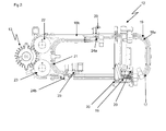
- FIG. 3 shows a view of module 3 (13).
- Module 3 (13) is the so-called take-over and press-in unit. The slides are taken from the carriers (28).
- acquisition / transfer heads (25) include vacuum suction heads, which suck the films from the carriers (28).
- the takeover and press-in unit (module 3) (13) is in particular rotatable about an axis parallel to the axis of the die table (26) of the tablet press (14).
- Module 3 (13) comprises in particular a rotor which is provided with radial arms and in the head parts radially movable transfer / transfer heads (25) are mounted, which can be brought to the transfer of the films with the matrices in coverage.
- the module 3 (13) is rotatable and capable of performing the same rotational speed as the tablet press (14).
- the films are inserted into the die openings of the tablet press (14).
- the transfer / transfer heads (25) of module 3 (13) for example vacuum heads, can be positioned directly above or in the die openings of a tablet press (14) in order to load the films.
- the transfer / transfer heads (25) are vertically adjustable, in particular by means of control cams.
- the transfer / transfer heads (25) can be retracted horizontally to bring them into coincidence with the die opening. In this way, a precise and centric positioning of the films in the mold of a tablet press (14) is possible.
- FIG. 4 shows the top view of a tablet press (14) with upper punch heads (27), which dive in particular in the die openings in order to compress the powder and thus to coat the inserted film.
- the tablet press (14) used to make coated tablets comprises a rotary driven die table (26) with dies arranged on a pitch circle.
- the tablet press (14) which is suitable for the production of coated tablets with inserted films, comprises not only one but in particular two filling devices for powders in the jacket core design on the pitch circle of the die table (26). These two powder fillers contain the powder with which the foil in the jacket tablet is sheathed. With a powder filling device powder is placed in the die, then inserted the film and finally covered with the second powder filling the film.
- the powder filling devices contain different types of powder, if necessary. After filling the matrix with powder, the film by means of module 3 (13) and again powder is followed by the actual pressing process, with which the tablet is produced comprising a sheathed film.
- FIG. 5 shows, for example, how the modules 1 (11) to 3 (13) and tablet press (14) can be interconnected or arranged to remove the films from the storage container or storage magazine and finally insert into the tablet press (14).
- the individual modules are height adjustable or matched in height to each other.
- the device in FIG. 5 can be individually in its capacity by, for example, additional length of the conveyor belts (17, 21), higher number of carriers (28), multiple carrier tapes in the feeder (15) of the module 1 (11), the number of picking heads in the "Pick and Place” Unit (16) and, for example, the number of webs are individually adapted to the required throughput when inserting the films in the tablet press (14).
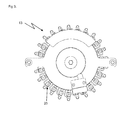
- FIG. 6 shows, for example, a carrier (28) with a receiving bore (29) for the film.
- the carriers (28) are preferably made of stainless steel. This has the advantage that the carriers (28) have a weight that allows stable transport on the conveyor belt (17, 21). It is further preferred that the carriers (28) also comprise plastic.
- the plastic part of the carrier (28) in particular represents the contact surface between the film and the carrier (28).
- the carrier (28) has a receiving bore (29) for the film at the contact surface, whereby the film is centered and penetrated through the depression (29 ) can not fall from the carrier (28) during transport, but is guided centered.
Priority Applications (11)
| Application Number | Priority Date | Filing Date | Title |
|---|---|---|---|
| ES13176062.1T ES2637382T3 (es) | 2013-07-11 | 2013-07-11 | Dispositivo y procedimiento para insertar películas en prensas para comprimidos |
| EP13176062.1A EP2823799B1 (fr) | 2013-07-11 | 2013-07-11 | Dispositif et procédé d'insertion de feuilles dans des presses à comprimés |
| JP2015516651A JP5866483B2 (ja) | 2013-05-16 | 2014-05-16 | 打錠機にフィルムを挿入する装置及び方法 |
| CN201811064402.2A CN109228493B (zh) | 2013-05-16 | 2014-05-16 | 用于在压片机的模具中传送、插入和定位薄膜的方法 |
| PCT/EP2014/060130 WO2014184364A1 (fr) | 2013-05-16 | 2014-05-16 | Dispositif et procédé d'insertion de feuilles dans des presses à pastiller |
| KR1020147033367A KR101648660B1 (ko) | 2013-05-16 | 2014-05-16 | 태블릿 프레스 내로 필름을 피착시키기 위한 장치 및 방법 |
| IN9338DEN2014 IN2014DN09338A (fr) | 2013-05-16 | 2014-05-16 | |
| CN201480001715.7A CN104411283B (zh) | 2013-05-16 | 2014-05-16 | 用于将薄膜放置在压片机中的装置和方法 |
| US14/403,582 US9248621B2 (en) | 2013-05-16 | 2014-05-16 | Apparatus and method for the insertion of films in tablet presses |
| JP2016000069A JP6156955B2 (ja) | 2013-05-16 | 2016-01-04 | 打錠機にフィルムを挿入する装置及び方法 |
| US14/990,977 US9452583B2 (en) | 2013-05-16 | 2016-01-08 | Apparatus and method for the insertion of films in tablet presses |
Applications Claiming Priority (1)
| Application Number | Priority Date | Filing Date | Title |
|---|---|---|---|
| EP13176062.1A EP2823799B1 (fr) | 2013-07-11 | 2013-07-11 | Dispositif et procédé d'insertion de feuilles dans des presses à comprimés |
Publications (2)
| Publication Number | Publication Date |
|---|---|
| EP2823799A1 true EP2823799A1 (fr) | 2015-01-14 |
| EP2823799B1 EP2823799B1 (fr) | 2017-05-17 |
Family
ID=48783006
Family Applications (1)
| Application Number | Title | Priority Date | Filing Date |
|---|---|---|---|
| EP13176062.1A Active EP2823799B1 (fr) | 2013-05-16 | 2013-07-11 | Dispositif et procédé d'insertion de feuilles dans des presses à comprimés |
Country Status (2)
| Country | Link |
|---|---|
| EP (1) | EP2823799B1 (fr) |
| ES (1) | ES2637382T3 (fr) |
Cited By (3)
| Publication number | Priority date | Publication date | Assignee | Title |
|---|---|---|---|---|
| WO2017211520A1 (fr) * | 2016-06-08 | 2017-12-14 | Schunk Kohlenstofftechnik Gmbh | Dispositif et procédé de production d'un corps moulé par pressage |
| CN109311254A (zh) * | 2016-06-08 | 2019-02-05 | 申克碳化技术股份有限公司 | 用于制造压缩成型体的设备和方法 |
| EP3599087A1 (fr) * | 2018-07-25 | 2020-01-29 | Korsch AG | Dispositif de fourniture des inserts à une machine à fabriquer des comprimés ainsi que procédé de fabrication d'un comprimé comportant un insert |
Citations (6)
| Publication number | Priority date | Publication date | Assignee | Title |
|---|---|---|---|---|
| US3836299A (en) * | 1973-08-13 | 1974-09-17 | Fmc Corp | Press for forming one-piece tablet containing seeds or the like |
| EP0349777A1 (fr) * | 1988-06-08 | 1990-01-10 | Korsch Maschinenfabrik | Presse pour enrober des noyaux |
| JPH09271996A (ja) * | 1996-04-05 | 1997-10-21 | Sankyo Co Ltd | タブレット自動成形装置 |
| EP1944002A2 (fr) * | 2004-09-24 | 2008-07-16 | BioProgress Technology Limited | Améliorations supplémentaires dans le compactage et l'enrobage de poudre |
| DE102007039043A1 (de) * | 2007-08-17 | 2009-02-19 | Grünenthal GmbH | Sternverteiler |
| EP2110232A2 (fr) * | 2008-04-18 | 2009-10-21 | Korsch AG | Procédé et dispositif d'insertion d'inserts dans des matrices d'une presse rotative pour comprimés |
-
2013
- 2013-07-11 EP EP13176062.1A patent/EP2823799B1/fr active Active
- 2013-07-11 ES ES13176062.1T patent/ES2637382T3/es active Active
Patent Citations (6)
| Publication number | Priority date | Publication date | Assignee | Title |
|---|---|---|---|---|
| US3836299A (en) * | 1973-08-13 | 1974-09-17 | Fmc Corp | Press for forming one-piece tablet containing seeds or the like |
| EP0349777A1 (fr) * | 1988-06-08 | 1990-01-10 | Korsch Maschinenfabrik | Presse pour enrober des noyaux |
| JPH09271996A (ja) * | 1996-04-05 | 1997-10-21 | Sankyo Co Ltd | タブレット自動成形装置 |
| EP1944002A2 (fr) * | 2004-09-24 | 2008-07-16 | BioProgress Technology Limited | Améliorations supplémentaires dans le compactage et l'enrobage de poudre |
| DE102007039043A1 (de) * | 2007-08-17 | 2009-02-19 | Grünenthal GmbH | Sternverteiler |
| EP2110232A2 (fr) * | 2008-04-18 | 2009-10-21 | Korsch AG | Procédé et dispositif d'insertion d'inserts dans des matrices d'une presse rotative pour comprimés |
Cited By (5)
| Publication number | Priority date | Publication date | Assignee | Title |
|---|---|---|---|---|
| WO2017211520A1 (fr) * | 2016-06-08 | 2017-12-14 | Schunk Kohlenstofftechnik Gmbh | Dispositif et procédé de production d'un corps moulé par pressage |
| CN109311254A (zh) * | 2016-06-08 | 2019-02-05 | 申克碳化技术股份有限公司 | 用于制造压缩成型体的设备和方法 |
| CN109311254B (zh) * | 2016-06-08 | 2021-03-09 | 申克碳化技术股份有限公司 | 用于制造压缩成型体的设备和方法 |
| EP3599087A1 (fr) * | 2018-07-25 | 2020-01-29 | Korsch AG | Dispositif de fourniture des inserts à une machine à fabriquer des comprimés ainsi que procédé de fabrication d'un comprimé comportant un insert |
| WO2020020662A1 (fr) | 2018-07-25 | 2020-01-30 | Korsch Ag | Dispositif servant à fournir des pièces d'insertion en tant que grilles d'appui sur une machine de production de comprimés, et procédé servant à fabriquer une ébauche, qui comporte une grille d'appui |
Also Published As
| Publication number | Publication date |
|---|---|
| EP2823799B1 (fr) | 2017-05-17 |
| ES2637382T3 (es) | 2017-10-13 |
Similar Documents
| Publication | Publication Date | Title |
|---|---|---|
| EP1973511B9 (fr) | Installation de production automatique d'emballages de produits medicaux et/ou pharmaceutiques et/ou de complements alimentaires | |
| EP1647487B1 (fr) | Procédé et dispositif pour placer des comprimés dans les alvéoles formés dans une feuille | |
| EP0803440B1 (fr) | Procédé et dispositif pour remplir des alvéoles d'un film avec des produits | |
| DE2358824A1 (de) | Verfahren und vorrichtung zum auftragen von kennzeichen | |
| EP1713693A1 (fr) | Procede et dispositif pour transferer des produits depuis un reservoir de stockage vers les evidements d'une feuille | |
| EP2823799B1 (fr) | Dispositif et procédé d'insertion de feuilles dans des presses à comprimés | |
| WO2002100747A1 (fr) | Dispositif et procede de transfert de sacs en film mince | |
| EP2240369A1 (fr) | Dispositif et procédé d'emballage pour grouper une configuration d'emballage de paquets | |
| EP2995581B1 (fr) | Station d'empilement pour une installation de thermoformage, procede de fabrication de produits en forme de gobelets et installation de thermoformage | |
| EP3003874B1 (fr) | Procédé et dispositif permettant de produire des unités d'emballage dans une ensacheuse verticale | |
| WO2014184364A1 (fr) | Dispositif et procédé d'insertion de feuilles dans des presses à pastiller | |
| DE60212985T2 (de) | Eine vorrichtung zur zuführung von produkten zu blisterherstellungsmaschinen | |
| WO2023285269A2 (fr) | Système d'empilement de cellules et dispositif d'empilement de cellules pour segments de cellules énergétiques et dispositif/procédé de division d'un système d'empilement de cellules ou dans un système d'empilement de cellules | |
| EP3222414B1 (fr) | Presse a comprimes rotative comprenant des poinçons ayant au moins deux pointes de poinçons echelonnees en hauteur destinee a executer plusieurs procedes de presse pendant une rotation | |
| DE102008027624A1 (de) | Verfahren und Vorrichtung zum Kontrollieren und Sortieren von Kleinteilen | |
| EP2805633B9 (fr) | Casier en matière synthétique conductrice d'électricité ainsi que dispositif et procédé de vidange automatique de casiers remplis de produits en forme de tiges | |
| WO2017198768A2 (fr) | Transporteur-élévateur | |
| DE1481026A1 (de) | Verfahren und Vorrichtung zum Foerdern laenglicher Gegenstaende,insbesondere Zigaretten | |
| DE102013104344B4 (de) | Vorrichtung zum Einlegen von Einlegern in Matrizen einer Tablettenpresse | |
| DE112016001284B4 (de) | Gruppierungseinheit und Verfahren zum Bilden von Gruppen von absorbierenden Hygieneartikeln in einer Verpackungsmaschine | |
| DE1911759C3 (de) | Einrichtung zum Herstellen von Weichkäse | |
| WO2014117960A1 (fr) | Dispositif de transfert et de positionnement d'un comprimé ou d'une ébauche de comprimé | |
| EP3909872A1 (fr) | Procédé et agencement de transport de produits | |
| DE102014112840B4 (de) | Einlegemaschine und Einlegeverfahren | |
| EP0224744A1 (fr) | Dispositif pour fabriquer des bandes d'éléments de construction en forme de tiges, notamment d'éléments de construction électriques (MELFs) |
Legal Events
| Date | Code | Title | Description |
|---|---|---|---|
| 17P | Request for examination filed |
Effective date: 20130711 |
|
| AK | Designated contracting states |
Kind code of ref document: A1 Designated state(s): AL AT BE BG CH CY CZ DE DK EE ES FI FR GB GR HR HU IE IS IT LI LT LU LV MC MK MT NL NO PL PT RO RS SE SI SK SM TR |
|
| AX | Request for extension of the european patent |
Extension state: BA ME |
|
| PUAI | Public reference made under article 153(3) epc to a published international application that has entered the european phase |
Free format text: ORIGINAL CODE: 0009012 |
|
| R17P | Request for examination filed (corrected) |
Effective date: 20150713 |
|
| RBV | Designated contracting states (corrected) |
Designated state(s): AL AT BE BG CH CY CZ DE DK EE ES FI FR GB GR HR HU IE IS IT LI LT LU LV MC MK MT NL NO PL PT RO RS SE SI SK SM TR |
|
| GRAP | Despatch of communication of intention to grant a patent |
Free format text: ORIGINAL CODE: EPIDOSNIGR1 |
|
| RIC1 | Information provided on ipc code assigned before grant |
Ipc: A61J 3/06 20060101AFI20161201BHEP Ipc: B30B 11/34 20060101ALN20161201BHEP Ipc: A61J 3/10 20060101ALI20161201BHEP Ipc: B30B 15/30 20060101ALN20161201BHEP Ipc: B30B 11/08 20060101ALI20161201BHEP Ipc: A61K 9/28 20060101ALN20161201BHEP |
|
| INTG | Intention to grant announced |
Effective date: 20161221 |
|
| GRAS | Grant fee paid |
Free format text: ORIGINAL CODE: EPIDOSNIGR3 |
|
| GRAA | (expected) grant |
Free format text: ORIGINAL CODE: 0009210 |
|
| AK | Designated contracting states |
Kind code of ref document: B1 Designated state(s): AL AT BE BG CH CY CZ DE DK EE ES FI FR GB GR HR HU IE IS IT LI LT LU LV MC MK MT NL NO PL PT RO RS SE SI SK SM TR |
|
| REG | Reference to a national code |
Ref country code: GB Ref legal event code: FG4D Free format text: NOT ENGLISH |
|
| REG | Reference to a national code |
Ref country code: CH Ref legal event code: EP |
|
| REG | Reference to a national code |
Ref country code: IE Ref legal event code: FG4D Free format text: LANGUAGE OF EP DOCUMENT: GERMAN |
|
| REG | Reference to a national code |
Ref country code: AT Ref legal event code: REF Ref document number: 893797 Country of ref document: AT Kind code of ref document: T Effective date: 20170615 |
|
| REG | Reference to a national code |
Ref country code: DE Ref legal event code: R096 Ref document number: 502013007263 Country of ref document: DE |
|
| REG | Reference to a national code |
Ref country code: FR Ref legal event code: PLFP Year of fee payment: 5 |
|
| REG | Reference to a national code |
Ref country code: NL Ref legal event code: MP Effective date: 20170517 |
|
| REG | Reference to a national code |
Ref country code: LT Ref legal event code: MG4D |
|
| REG | Reference to a national code |
Ref country code: ES Ref legal event code: FG2A Ref document number: 2637382 Country of ref document: ES Kind code of ref document: T3 Effective date: 20171013 |
|
| PG25 | Lapsed in a contracting state [announced via postgrant information from national office to epo] |
Ref country code: HR Free format text: LAPSE BECAUSE OF FAILURE TO SUBMIT A TRANSLATION OF THE DESCRIPTION OR TO PAY THE FEE WITHIN THE PRESCRIBED TIME-LIMIT Effective date: 20170517 Ref country code: FI Free format text: LAPSE BECAUSE OF FAILURE TO SUBMIT A TRANSLATION OF THE DESCRIPTION OR TO PAY THE FEE WITHIN THE PRESCRIBED TIME-LIMIT Effective date: 20170517 Ref country code: GR Free format text: LAPSE BECAUSE OF FAILURE TO SUBMIT A TRANSLATION OF THE DESCRIPTION OR TO PAY THE FEE WITHIN THE PRESCRIBED TIME-LIMIT Effective date: 20170818 Ref country code: LT Free format text: LAPSE BECAUSE OF FAILURE TO SUBMIT A TRANSLATION OF THE DESCRIPTION OR TO PAY THE FEE WITHIN THE PRESCRIBED TIME-LIMIT Effective date: 20170517 Ref country code: NO Free format text: LAPSE BECAUSE OF FAILURE TO SUBMIT A TRANSLATION OF THE DESCRIPTION OR TO PAY THE FEE WITHIN THE PRESCRIBED TIME-LIMIT Effective date: 20170817 |
|
| PG25 | Lapsed in a contracting state [announced via postgrant information from national office to epo] |
Ref country code: RS Free format text: LAPSE BECAUSE OF FAILURE TO SUBMIT A TRANSLATION OF THE DESCRIPTION OR TO PAY THE FEE WITHIN THE PRESCRIBED TIME-LIMIT Effective date: 20170517 Ref country code: SE Free format text: LAPSE BECAUSE OF FAILURE TO SUBMIT A TRANSLATION OF THE DESCRIPTION OR TO PAY THE FEE WITHIN THE PRESCRIBED TIME-LIMIT Effective date: 20170517 Ref country code: IS Free format text: LAPSE BECAUSE OF FAILURE TO SUBMIT A TRANSLATION OF THE DESCRIPTION OR TO PAY THE FEE WITHIN THE PRESCRIBED TIME-LIMIT Effective date: 20170917 Ref country code: BG Free format text: LAPSE BECAUSE OF FAILURE TO SUBMIT A TRANSLATION OF THE DESCRIPTION OR TO PAY THE FEE WITHIN THE PRESCRIBED TIME-LIMIT Effective date: 20170817 Ref country code: PL Free format text: LAPSE BECAUSE OF FAILURE TO SUBMIT A TRANSLATION OF THE DESCRIPTION OR TO PAY THE FEE WITHIN THE PRESCRIBED TIME-LIMIT Effective date: 20170517 Ref country code: NL Free format text: LAPSE BECAUSE OF FAILURE TO SUBMIT A TRANSLATION OF THE DESCRIPTION OR TO PAY THE FEE WITHIN THE PRESCRIBED TIME-LIMIT Effective date: 20170517 Ref country code: LV Free format text: LAPSE BECAUSE OF FAILURE TO SUBMIT A TRANSLATION OF THE DESCRIPTION OR TO PAY THE FEE WITHIN THE PRESCRIBED TIME-LIMIT Effective date: 20170517 |
|
| PG25 | Lapsed in a contracting state [announced via postgrant information from national office to epo] |
Ref country code: DK Free format text: LAPSE BECAUSE OF FAILURE TO SUBMIT A TRANSLATION OF THE DESCRIPTION OR TO PAY THE FEE WITHIN THE PRESCRIBED TIME-LIMIT Effective date: 20170517 Ref country code: EE Free format text: LAPSE BECAUSE OF FAILURE TO SUBMIT A TRANSLATION OF THE DESCRIPTION OR TO PAY THE FEE WITHIN THE PRESCRIBED TIME-LIMIT Effective date: 20170517 Ref country code: CZ Free format text: LAPSE BECAUSE OF FAILURE TO SUBMIT A TRANSLATION OF THE DESCRIPTION OR TO PAY THE FEE WITHIN THE PRESCRIBED TIME-LIMIT Effective date: 20170517 Ref country code: RO Free format text: LAPSE BECAUSE OF FAILURE TO SUBMIT A TRANSLATION OF THE DESCRIPTION OR TO PAY THE FEE WITHIN THE PRESCRIBED TIME-LIMIT Effective date: 20170517 Ref country code: SK Free format text: LAPSE BECAUSE OF FAILURE TO SUBMIT A TRANSLATION OF THE DESCRIPTION OR TO PAY THE FEE WITHIN THE PRESCRIBED TIME-LIMIT Effective date: 20170517 |
|
| REG | Reference to a national code |
Ref country code: DE Ref legal event code: R097 Ref document number: 502013007263 Country of ref document: DE |
|
| PG25 | Lapsed in a contracting state [announced via postgrant information from national office to epo] |
Ref country code: SM Free format text: LAPSE BECAUSE OF FAILURE TO SUBMIT A TRANSLATION OF THE DESCRIPTION OR TO PAY THE FEE WITHIN THE PRESCRIBED TIME-LIMIT Effective date: 20170517 |
|
| REG | Reference to a national code |
Ref country code: CH Ref legal event code: PL |
|
| PLBE | No opposition filed within time limit |
Free format text: ORIGINAL CODE: 0009261 |
|
| STAA | Information on the status of an ep patent application or granted ep patent |
Free format text: STATUS: NO OPPOSITION FILED WITHIN TIME LIMIT |
|
| REG | Reference to a national code |
Ref country code: IE Ref legal event code: MM4A |
|
| 26N | No opposition filed |
Effective date: 20180220 |
|
| GBPC | Gb: european patent ceased through non-payment of renewal fee |
Effective date: 20170817 |
|
| PG25 | Lapsed in a contracting state [announced via postgrant information from national office to epo] |
Ref country code: IE Free format text: LAPSE BECAUSE OF NON-PAYMENT OF DUE FEES Effective date: 20170711 Ref country code: CH Free format text: LAPSE BECAUSE OF NON-PAYMENT OF DUE FEES Effective date: 20170731 Ref country code: LI Free format text: LAPSE BECAUSE OF NON-PAYMENT OF DUE FEES Effective date: 20170731 |
|
| PG25 | Lapsed in a contracting state [announced via postgrant information from national office to epo] |
Ref country code: SI Free format text: LAPSE BECAUSE OF FAILURE TO SUBMIT A TRANSLATION OF THE DESCRIPTION OR TO PAY THE FEE WITHIN THE PRESCRIBED TIME-LIMIT Effective date: 20170517 |
|
| PG25 | Lapsed in a contracting state [announced via postgrant information from national office to epo] |
Ref country code: LU Free format text: LAPSE BECAUSE OF NON-PAYMENT OF DUE FEES Effective date: 20170711 |
|
| REG | Reference to a national code |
Ref country code: FR Ref legal event code: PLFP Year of fee payment: 6 |
|
| PG25 | Lapsed in a contracting state [announced via postgrant information from national office to epo] |
Ref country code: GB Free format text: LAPSE BECAUSE OF NON-PAYMENT OF DUE FEES Effective date: 20170817 |
|
| PG25 | Lapsed in a contracting state [announced via postgrant information from national office to epo] |
Ref country code: MT Free format text: LAPSE BECAUSE OF FAILURE TO SUBMIT A TRANSLATION OF THE DESCRIPTION OR TO PAY THE FEE WITHIN THE PRESCRIBED TIME-LIMIT Effective date: 20170517 |
|
| PG25 | Lapsed in a contracting state [announced via postgrant information from national office to epo] |
Ref country code: HU Free format text: LAPSE BECAUSE OF FAILURE TO SUBMIT A TRANSLATION OF THE DESCRIPTION OR TO PAY THE FEE WITHIN THE PRESCRIBED TIME-LIMIT; INVALID AB INITIO Effective date: 20130711 Ref country code: MC Free format text: LAPSE BECAUSE OF FAILURE TO SUBMIT A TRANSLATION OF THE DESCRIPTION OR TO PAY THE FEE WITHIN THE PRESCRIBED TIME-LIMIT Effective date: 20170517 |
|
| REG | Reference to a national code |
Ref country code: AT Ref legal event code: MM01 Ref document number: 893797 Country of ref document: AT Kind code of ref document: T Effective date: 20180711 |
|
| PG25 | Lapsed in a contracting state [announced via postgrant information from national office to epo] |
Ref country code: CY Free format text: LAPSE BECAUSE OF FAILURE TO SUBMIT A TRANSLATION OF THE DESCRIPTION OR TO PAY THE FEE WITHIN THE PRESCRIBED TIME-LIMIT Effective date: 20170517 |
|
| PG25 | Lapsed in a contracting state [announced via postgrant information from national office to epo] |
Ref country code: MK Free format text: LAPSE BECAUSE OF FAILURE TO SUBMIT A TRANSLATION OF THE DESCRIPTION OR TO PAY THE FEE WITHIN THE PRESCRIBED TIME-LIMIT Effective date: 20170517 |
|
| PG25 | Lapsed in a contracting state [announced via postgrant information from national office to epo] |
Ref country code: AT Free format text: LAPSE BECAUSE OF NON-PAYMENT OF DUE FEES Effective date: 20180711 |
|
| PG25 | Lapsed in a contracting state [announced via postgrant information from national office to epo] |
Ref country code: TR Free format text: LAPSE BECAUSE OF FAILURE TO SUBMIT A TRANSLATION OF THE DESCRIPTION OR TO PAY THE FEE WITHIN THE PRESCRIBED TIME-LIMIT Effective date: 20170517 |
|
| PG25 | Lapsed in a contracting state [announced via postgrant information from national office to epo] |
Ref country code: PT Free format text: LAPSE BECAUSE OF FAILURE TO SUBMIT A TRANSLATION OF THE DESCRIPTION OR TO PAY THE FEE WITHIN THE PRESCRIBED TIME-LIMIT Effective date: 20170517 |
|
| PG25 | Lapsed in a contracting state [announced via postgrant information from national office to epo] |
Ref country code: AL Free format text: LAPSE BECAUSE OF FAILURE TO SUBMIT A TRANSLATION OF THE DESCRIPTION OR TO PAY THE FEE WITHIN THE PRESCRIBED TIME-LIMIT Effective date: 20170517 |
|
| PGFP | Annual fee paid to national office [announced via postgrant information from national office to epo] |
Ref country code: IT Payment date: 20220729 Year of fee payment: 10 Ref country code: ES Payment date: 20220819 Year of fee payment: 10 Ref country code: DE Payment date: 20220602 Year of fee payment: 10 |
|
| PGFP | Annual fee paid to national office [announced via postgrant information from national office to epo] |
Ref country code: FR Payment date: 20220727 Year of fee payment: 10 Ref country code: BE Payment date: 20220720 Year of fee payment: 10 |
|
| P01 | Opt-out of the competence of the unified patent court (upc) registered |
Effective date: 20230508 |
|
| REG | Reference to a national code |
Ref country code: DE Ref legal event code: R119 Ref document number: 502013007263 Country of ref document: DE |
|
| REG | Reference to a national code |
Ref country code: BE Ref legal event code: MM Effective date: 20230731 |
|
| PG25 | Lapsed in a contracting state [announced via postgrant information from national office to epo] |
Ref country code: DE Free format text: LAPSE BECAUSE OF NON-PAYMENT OF DUE FEES Effective date: 20240201 |