EP2821568B1 - Verriegelungseinrichtung, insbesondere Schließzylinder - Google Patents
Verriegelungseinrichtung, insbesondere Schließzylinder Download PDFInfo
- Publication number
- EP2821568B1 EP2821568B1 EP14450032.9A EP14450032A EP2821568B1 EP 2821568 B1 EP2821568 B1 EP 2821568B1 EP 14450032 A EP14450032 A EP 14450032A EP 2821568 B1 EP2821568 B1 EP 2821568B1
- Authority
- EP
- European Patent Office
- Prior art keywords
- coupling
- locking device
- rotary handle
- shaft
- handle
- Prior art date
- Legal status (The legal status is an assumption and is not a legal conclusion. Google has not performed a legal analysis and makes no representation as to the accuracy of the status listed.)
- Not-in-force
Links
- 230000008878 coupling Effects 0.000 claims description 47
- 238000010168 coupling process Methods 0.000 claims description 47
- 238000005859 coupling reaction Methods 0.000 claims description 47
- 230000005674 electromagnetic induction Effects 0.000 claims description 2
- 230000006378 damage Effects 0.000 description 2
- 238000001665 trituration Methods 0.000 description 2
- 238000013475 authorization Methods 0.000 description 1
- 230000000903 blocking effect Effects 0.000 description 1
- 150000001875 compounds Chemical class 0.000 description 1
- 238000001514 detection method Methods 0.000 description 1
- 230000006870 function Effects 0.000 description 1
- 238000004519 manufacturing process Methods 0.000 description 1
- 238000009987 spinning Methods 0.000 description 1
Images
Classifications
-
- E—FIXED CONSTRUCTIONS
- E05—LOCKS; KEYS; WINDOW OR DOOR FITTINGS; SAFES
- E05B—LOCKS; ACCESSORIES THEREFOR; HANDCUFFS
- E05B47/00—Operating or controlling locks or other fastening devices by electric or magnetic means
- E05B47/06—Controlling mechanically-operated bolts by electro-magnetically-operated detents
- E05B47/0611—Cylinder locks with electromagnetic control
- E05B47/0638—Cylinder locks with electromagnetic control by disconnecting the rotor
-
- E—FIXED CONSTRUCTIONS
- E05—LOCKS; KEYS; WINDOW OR DOOR FITTINGS; SAFES
- E05B—LOCKS; ACCESSORIES THEREFOR; HANDCUFFS
- E05B13/00—Devices preventing the key or the handle or both from being used
- E05B13/005—Disconnecting the handle
-
- E—FIXED CONSTRUCTIONS
- E05—LOCKS; KEYS; WINDOW OR DOOR FITTINGS; SAFES
- E05B—LOCKS; ACCESSORIES THEREFOR; HANDCUFFS
- E05B17/00—Accessories in connection with locks
- E05B17/0054—Fraction or shear lines; Slip-clutches, resilient parts or the like for preventing damage when forced or slammed
- E05B17/0058—Fraction or shear lines; Slip-clutches, resilient parts or the like for preventing damage when forced or slammed with non-destructive disengagement
-
- E—FIXED CONSTRUCTIONS
- E05—LOCKS; KEYS; WINDOW OR DOOR FITTINGS; SAFES
- E05B—LOCKS; ACCESSORIES THEREFOR; HANDCUFFS
- E05B47/00—Operating or controlling locks or other fastening devices by electric or magnetic means
- E05B47/06—Controlling mechanically-operated bolts by electro-magnetically-operated detents
- E05B47/0611—Cylinder locks with electromagnetic control
- E05B47/0615—Cylinder locks with electromagnetic control operated by handles, e.g. by knobs
-
- E—FIXED CONSTRUCTIONS
- E05—LOCKS; KEYS; WINDOW OR DOOR FITTINGS; SAFES
- E05B—LOCKS; ACCESSORIES THEREFOR; HANDCUFFS
- E05B47/00—Operating or controlling locks or other fastening devices by electric or magnetic means
- E05B47/06—Controlling mechanically-operated bolts by electro-magnetically-operated detents
- E05B47/0676—Controlling mechanically-operated bolts by electro-magnetically-operated detents by disconnecting the handle
- E05B47/0684—Controlling mechanically-operated bolts by electro-magnetically-operated detents by disconnecting the handle radially
- E05B47/0692—Controlling mechanically-operated bolts by electro-magnetically-operated detents by disconnecting the handle radially with a rectilinearly moveable coupling element
-
- E—FIXED CONSTRUCTIONS
- E05—LOCKS; KEYS; WINDOW OR DOOR FITTINGS; SAFES
- E05B—LOCKS; ACCESSORIES THEREFOR; HANDCUFFS
- E05B17/00—Accessories in connection with locks
- E05B17/0054—Fraction or shear lines; Slip-clutches, resilient parts or the like for preventing damage when forced or slammed
- E05B17/0062—Fraction or shear lines; Slip-clutches, resilient parts or the like for preventing damage when forced or slammed with destructive disengagement
-
- E—FIXED CONSTRUCTIONS
- E05—LOCKS; KEYS; WINDOW OR DOOR FITTINGS; SAFES
- E05B—LOCKS; ACCESSORIES THEREFOR; HANDCUFFS
- E05B47/00—Operating or controlling locks or other fastening devices by electric or magnetic means
- E05B2047/0048—Circuits, feeding, monitoring
- E05B2047/0057—Feeding
- E05B2047/0062—Feeding by generator
Definitions
- the invention relates to a locking device, in particular lock cylinder, comprising a locking member, a rotary handle, in particular rotary knob, and a rotatable member which is connected to the rotary handle by means of a rotationally fixed connection, wherein the rotary handle and the rotatable member in the idle state together freely rotatable and in the opening - or closed state with the locking member can be coupled.
- Electronic locking systems consist of an electronic identification medium in the form of memory cards or the like, which have stored an electronic key, and an access control device, such as a lock cylinder, with an electromechanical actuation. After reading the electronic key, the rotational movement of a handle, such as 2.B. a knob or handle via a corresponding coupling with a further rotatably mounted part rotatably coupled, which can actuate a bolt in the sequence.
- a handle such as 2.B. a knob or handle via a corresponding coupling with a further rotatably mounted part rotatably coupled
- electronic security systems which are designed as a double knob cylinder, wherein on one side of the door to be opened elements of a detection logic, and in particular antennas or the like., Are arranged, whereas the coupling of the rotational movement of this outer rotatable part after detecting the correct key via an electronics usually made by electrical means by coupling a coupling element.
- the external handle is freely rotatable without such a coupling.
- This freely rotatable handle is connected via a shaft with the opposite side of the door or the window on which the coupling is made with the actuator of the lock.
- the shaft is thereby passed with relatively little clearance through the lock cylinder, the free rotation at the same time relatively little play without the risk of jamming and without the risk of unintentional coupling must be guaranteed.
- a possible training is for example the DE 19851308 A1 can be seen in which the lock cylinder is provided on both sides with Drehknäufen, of which the inside door knob has access control electronics.
- an access authorization is determined, wherein a clutch is actuated electromagnetically in such a way that a locking bit can be moved from the outside door-side rotary knob.
- a doorknob which a Spindle with a clutch disc and a knob covers.
- extensions of the clutch disc and extensions of the knob engage each other so that the spindle is moved when the knob is rotated.
- the invention therefore aims to improve a locking device of the type mentioned in that the functionality is guaranteed even at very high rotational speeds and at high torques that are applied to the rotary handle.
- the locking device should also be able to fulfill its function after repeated sabotage attempts and / or a sabotage attempt should be recognizable to the user.
- the invention provides in a locking device of the type mentioned above, that an engageable between the rotary handle and the rotatable element coupling is provided which interrupts the rotational connection between the rotary handle and the rotatable element when a limit speed of the handle is exceeded.
- the rotary handle is rotatably connected in the normal state with a co-rotating with the rotary handle rotatable element.
- the rotary handle and the rotatable element are arranged coaxially in this rule.
- the invention also includes embodiments in which the rotary handle and the rotatable element do not rotate about the same axis of rotation.
- the arranged between the rotary handle and the rotatable element coupling can basically be performed arbitrarily. It is essential that the clutch is able to decouple the rotary handle when a limit speed is exceeded by the rotatable element, so that there is no rotationally fixed connection between these two components.
- the coupling may be designed to be after decoupling the rotary handle returns from the rotatable part of the decoupling state back to the coupling state, either automatically or after a corresponding user operation.
- the coupling can also be designed as a one-time clutch by the non-rotatable connection between the rotating handle and the rotatable element is not temporarily interrupted, but permanently interrupted or the corresponding connection means is even destroyed. In this way, a user can subsequently recognize the sabotage attempt. Furthermore, this prevents repeated sabotage attempts.
- the coupling is designed as a centrifugally controlled clutch.
- the coupling has at least one driver, which can be displaced from a radially inner position in the radial direction, preferably against the force of a spring element, into a radially outer position.
- the driver in this case acts in the inner position preferably positive fit with a radially inner coupling part of the rotary handle or a rotationally fixed to the rotary handle part and preferably a form-fitting manner with a radially outer coupling part of the rotatable element together.
- the preferably positive connection between the driver and the rotary handle is released, so that the rotary handle is decoupled from the rotatable element.
- the coupling can be actuated by electromagnetic induction, such as by an electric generator driven by the rotary handle or by eddy currents induced by the rotary handle. This succeeds in a simple manner controlled by the rotational speed of the rotary handle actuation of the clutch.
- the coupling shaft preferably forms the rotatable element.
- the clutch is then located between the rotary handle and the clutch shaft.
- a first portion of the coupling shaft is rotatably connected to the rotary handle and a second portion of the coupling shaft forms the rotatable member, wherein the coupling between the first portion and the second portion is arranged.
- electronic components such as a reading unit for reading the electronic key from the identification medium
- electronic components are arranged inside the rotary handle.
- these electronic components usually leads at least one cable into the interior of the lock cylinder, for example, to control a arranged there actuator for coupling the locking member.
- cables can also be led through the lock cylinder in order to electrically connect electrical components of an external handle with those of an internal handle.
- the coupling according to the invention therefore preferably has a cable feedthrough.
- at least one cable performed by the coupling is non-rotatably connected to the handle. As a result, said cable rotates in the normal state of the locking device with the rotary handle and with the rotatable element.
- the limit speed is at least 1,000, preferably at least 5,000, particularly preferably at least 10,000, rpm.
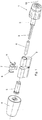
- Fig.1 a schematic overall view of a lock cylinder according to the invention in teilzerlegtem state
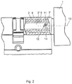
- Fig. 2 a detailed view of the locking device according to the invention.
- Fig. 1 is denoted by 1 a knob, which is freely rotatably connected via a hollow shaft 2 and a coupling shaft 3 with a housed in another knob 4 electromechanical clutch disc.
- the clutch disc itself may be formed in any desired manner and, for example, magnetically or mechanically coupled with a corresponding component, such as the knob 4.
- the actuating shaft is denoted by 5 and is penetrated by a sliding sleeve 6.
- a locking lug 7 is provided for the operation of the lock bolt, said locking lug 7 is held in the axial direction adjusted by corresponding snap rings 8 and rotatably connected to the actuating shaft 5, which in turn rotatably with the inside knob 4 or after the coupling rotatably connected to the clutch shaft 3 is connected.
- the knob 1 can be freely rotated together with the hollow shaft 2 mounted in the housing 9 and the associated coupling shaft 3 about the rotation axis 10.
- the coupling shaft 3 consists of two shaft sections 3 'and 3 ".
- the shaft section 3' is non-rotatably connected to the knob 1 and has a smaller diameter extension, which is encompassed by an annular extension of the shaft section 3".
- the shaft portion 3 ' has in its reduced diameter projection on a radial recess 13 in which a radially movable flyweight 11 is added.
- the flyweight 11 has such a radial dimension that it is in the in Fig. 2 shown radially inner layer in a radial recess 12 of the shaft portion 3 "dips and thereby produces a positive rotational connection between the two shaft sections 3 'and 3".
- the flyweight 11 is pressed radially inwardly by means of a spring element, not shown, to remain in normal operation, ie at the rotational speeds usually occurring in the radially inner layer.
- centrifugal force 11 acts on the centrifugal weight 11 such that it overcomes the spring force exerted by the spring element, not shown, and displaces it outwardly.
- the centrifugal weight 11 emerges from the recess 13, thereby separating the rotationally fixed connection between the shaft sections 3 'and 3 ".
- a centrifugal force-controlled coupling is thus realized between the shaft sections 3' and 3".
Landscapes
- Physics & Mathematics (AREA)
- Electromagnetism (AREA)
- One-Way And Automatic Clutches, And Combinations Of Different Clutches (AREA)
- Preventing Unauthorised Actuation Of Valves (AREA)
- Mechanical Control Devices (AREA)
Description
- Die Erfindung betrifft eine Verriegelungseinrichtung, insbesondere Schließzylinder, umfassend ein Verriegelungsglied, eine Drehhandhabe, insbesondere Drehknauf, und ein drehbewegliches Element, das mit der Drehhandhabe mittels einer drehfesten Verbindung verbunden ist, wobei die Drehhandhabe und das drehbewegliche Element im Ruhezustand gemeinsam frei drehbar und im Öffnungs- bzw. Schließzustand mit dem Verriegelungsglied kuppelbar sind.
- Elektronische Verriegelungssysteme bestehen aus einem elektronischen Identifikationsmedium in Form von Speicherkarten oder dgl., die einen elektronischen Schlüssel gespeichert haben, und einer Zutrittskontrollvorrichtung, wie z.B. einem Schließzylinder, mit einer elektromechanischen Betätigung. Nach dem Lesen des elektronischen Schlüssels wird die Drehbewegung einer Handhabe, wie 2.B. eines Knaufes oder Griffes über eine entsprechende Kupplung mit einem weiteren drehbar gelagerten Teil drehfest gekuppelt, welcher in der Folge einen Riegel betätigen kann. In diesem Zusammenhang sind elektronische Sicherheitssysteme bekannt geworden, welche als Doppelknaufzylinder ausgebildet sind, wobei an einer Seite der zu öffnenden Tür Elemente einer Erkennungslogik, und insbesondere Antennen oder dgl., angeordnet sind, wohingegen die Kupplung der Drehbewegung dieses außen liegenden drehbaren Teils nach Erkennen des korrekten Schlüssels über eine Elektronik zumeist auf elektrischem Weg durch Einkuppeln eines Kuppelglieds vorgenommen wird. Bei derartigen Einrichtungen ist ohne eine derartige Kupplung die außen liegende Handhabe frei drehbar. Diese frei drehbare Handhabe ist über eine Welle mit der gegenüberliegenden Seite der Türe oder des Fensters verbunden, an welcher die Kupplung mit dem Betätigungsglied des Schlosses vorgenommen wird. Die Welle wird hierbei mit relativ geringem Spiel durch den Schließzylinder hindurchgeführt, wobei die freie Drehbarkeit bei gleichzeitig relativ geringem Spiel ohne die Gefahr eines Klemmens und ohne die Gefahr einer unbeabsichtigten Kupplung gewährleistet sein muss. Eine mögliche Ausbildung ist beispielsweise der
DE 19851308 A1 zu entnehmen, bei welcher der Schließzylinder beidseitig mit Drehknäufen versehen ist, von denen der türinnenseitige Drehknauf eine Zutrittskontrollelektronik aufweist. In Abhängigkeit von der Identifikation eines Identmediums wird eine Zutrittsberechtigung festgestellt, wobei eine Kupplung elektromagnetisch derart betätigt wird, dass vom türaußenseitigen Drehknauf aus ein Schließbart bewegt werden kann. - Bedingt durch die geringen Toleranzen bei der Fertigung derartiger Sicherheitseinrichtungen hat sich aber nun gezeigt, dass eine mögliche missbräuchliche Manipulation dadurch geschaffen wird, dass an die frei drehbare Handhabe ein entsprechendes Antriebsaggregat, beispielsweise ein elektrischer Motor oder Federwerksmotor, angeschlossen wird, welches die Handhabe in rasche Rotation versetzt. Bei einer derartigen raschen Rotation wird eine entsprechende Reibungswärme im Inneren des Schlosses generiert, welche bei Ausdehnung der üblicherweise frei durchdrehenden Welle zu einem Verreiben oder aber einem unbeabsichtigten Kuppeln einer Außenwelle mit einer Innenwelle führen kann, sodass auf diese Weise trotz fehlender elektronischer Freigabe der Kupplung auf mechanischem Weg eine durch thermische Ausdehnung oder Verreiben erzielte Kupplung zwischen der üblicherweise frei drehbaren Handhabe und dem Sperrbart entsteht, wodurch das Schloss betätigt werden kann. Eine derartige Fehlbedienung bzw. Sabotagebedienung setzt allerdings voraus, dass die frei drehbare Handhabe über eine Mindestzeit auf eine entsprechende Mindestdrehzahl gebracht werden kann, welche zu einer thermischen Ausdehnung bzw. zum Verreiben führen kann.
- Um eine derartige Sabotage- bzw. Fehlbedienung auszuschließen und gleichzeitig zu gewährleisten, dass die frei drehbare Handhabe nur mit einer relativ geringen Drehgeschwindigkeit frei drehbar bleibt und in anderen Fällen einem Verreiben oder Verklemmen entgegenwirkt, ist in der
WO 2007/095652 A1 bereits eine Sicherheitseinrichtung der eingangs genannten Art vorgeschlagen worden, bei der mit der Handhabe wenigstens ein radial geführt verlagerbares Fliehgewicht gekuppelt ist, welches ab einer definierten Anzahl von Umdrehungen der Handhabe in einer Zeiteinheit mit einem ortsfesten Teil des Schlosses in Eingriff gelangt und die weitere Drehbewegung blockiert. Durch die Fliehkraftsperre wird gewährleistet, dass bei zu hoher Drehzahl der frei drehbaren Handhabe unmittelbar eine Blockade erfolgt. - Bei einer Sicherheitsvorrichtung des in der
WO 2007/095652 A1 beschriebenen Typs kann die korrekte Funktionsweise jedoch insbesondere in jenen Fällen nicht mit Sicherheit garantiert werden, in denen auf die Handhabe ein besonders hohes Drehmoment aufgebracht wird. Es besteht hierbei nämlich die Gefahr, dass die auf Grund der Fliehkraft verlagerbaren Elemente mechanisch überlastet und in weiterer Folge verformt oder zerstört werden. Nachteilig bei der beschriebenen Ausführung ist weiters, dass sich das Fliehgewicht im Blockierzustand am Schließzylindergehäuse abstützt, um die weitere Drehbewegung der Handhabe zu blockieren. Dies kann bei großer Krafteinwirkung jedoch zu regionalen Verformungen des Schließzylindergehäuses führen. Problematisch ist in beiden Fällen, dass die Verformung oder Zerstörung des Fliehgewichts bzw. des Gehäuses im Normalbetrieb des Schließzylinders für den Benutzer von außen nicht erkennbar ist, da der Sperrvorgang bei nicht missbräuchlicher Bedienung hierdurch nicht beeinträchtigt ist. - In der
US 1516152 wird ein Türknauf offenbart, welcher eine Spindel mit einer Kupplungsscheibe sowie einen Knauf umfasst. Im normalen Betriebszustand greifen Fortsätze der Kupplungsscheibe und Fortsätze des Knaufs ineinander, sodass die Spindel bewegt wird, wenn der Knauf gedreht wird. Blockiert nun die Spindel und wird ein hohes Drehmoment auf den Knauf aufgebracht, so rutschen die Fortsätze und relativ zueinander und der Knauf dreht sich, die Spindel aber nicht. Dadurch soll verhindert werden, dass der Türknauf beschädigt wird, wenn die Spindel blockiert. - Die Erfindung zielt daher darauf ab, eine Verriegelungseinrichtung der eingangs genannten Art dahingehend zu verbessern, dass die Funktionsfähigkeit auch bei sehr hohen Umdrehungsgeschwindigkeiten und bei hohen Drehmomenten, die auf die Drehhandhabe aufgebracht werden, gewährleistet ist. Die Verriegelungseinrichtung soll auch nach mehrmaligen Sabotageversuchen ihre Funktion erfüllen können und/oder ein Sabotageversuch für den Benutzer erkennbar sein.
- Zur Lösung dieser Aufgabe sieht die Erfindung bei einer Verriegelungseinrichtung der eingangs genannten Art vor, dass eine zwischen der Drehhandhabe und dem drehbeweglichen Element anordenbare Kupplung vorgesehen ist, welche bei Überschreiten einer Grenzdrehzahl der Handhabe die drehfeste Verbindung zwischen der Drehhandhabe und dem drehbeweglichen Element unterbricht. Somit wird bei einem Sabotageversuch im Gegensatz zum Stand der Technik nicht die Drehbewegung der Drehhandhabe blockiert, sondern die Drehhandhabe von einem in der Verriegelungseinrichtung, insbesondere Schließzylinder angeordneten drehbeweglichen Teil entkoppelt. Im entkoppelten Zustand der Drehhandhabe können im Inneren des Schließzylinders keine Zustände mehr auftreten, bei denen ein mit dem Verriegelungsglied drehfest verbundener Bauteil unbeabsichtigt mitgeschleppt wird, da die entsprechenden Bauteile sich nicht mehr in Drehbewegung befinden. Weiters ist die Funktionalität der Verriegelungseinrichtung unabhängig vom auftretenden Drehmoment sichergestellt, da das Drehmoment im entkoppelten Zustand der Drehhandhabe nicht mehr auf kritische Bauteile übertragen wird. Eine Verformung oder Zerstörung von in der Verriegelungseinrichtung angeordneten kritischen Bauteilen ist daher ausgeschlossen.
- Im Rahmen der Erfindung ist vorgesehen, dass die Drehhandhabe im Normalzustand mit einem mit der Drehhandhabe mitdrehenden drehbeweglichen Element drehfest verbunden ist. Dies umfasst nicht nur Ausbildungen, bei denen die Drehhandhabe unmittelbar mit dem drehbeweglichen Element drehfest verbunden ist, sondern auch Ausbildungen, bei denen die Drehhandhabe unter Zwischenschaltung wenigstens eines weiteren Bauteils mit dem drehbeweglichen Element drehfest verbunden ist.
- Unter einer drehfesten Verbindung ist in Rahmen der Erfindung eine Verbindung zu verstehen, bei der die Handhabe und das drehbewegliche Element im Normalzustand mit gleicher Drehzahl rotieren oder in einem festen Drehzahlverhältnis drehgekoppelt sind. Die Drehhandhabe und das drehbewegliche Element sind hierbei in der Regel koaxial angeordnet. Die Erfindung umfasst aber auch Ausführungen, bei denen die Drehhandhabe und das drehbewegliche Element nicht um die gleiche Drehachse rotieren.
- Die zwischen der Drehhandhabe und dem drehbeweglichen Element angeordnete Kupplung kann grundsätzlich beliebig ausgeführt sein. Wesentlich ist, dass die Kupplung in der Lage ist, die Drehhandhabe bei Überschreiten einer Grenzdrehzahl von dem drehbeweglichen Element zu entkoppeln, sodass zwischen diesen beiden Bauteilen keine drehfeste Verbindung mehr besteht. Die Kupplung kann so ausgebildet sein, dass sie nach der Entkopplung der Drehhandhabe vom drehbeweglichen Teil vom Entkopplungszustand wieder zurück in den Kopplungszustand zurückkehrt, und zwar entweder automatisch oder nach einer entsprechenden Benutzerbetätigung. Alternativ kann die Kupplung auch als Einmalkupplung ausgebildet sein, indem die drehfeste Verbindung zwischen der Drehhandhabe und dem drehbeweglichen Element nicht temporär unterbrochen, sondern dauerhaft unterbrochen oder das entsprechende Verbindungsmittel gar zerstört wird. Auf diese Weise kann ein Benutzer den Sabotageversuch nachträglich erkennen. Weiters werden dadurch wiederholte Sabotageversuche verhindert.
- Eine bevorzugte Ausbildung sieht vor, dass die Kupplung als fliehkraftgesteuerte Kupplung ausgebildet ist. Insbesondere weist die Kupplung wenigstens einen Mitnehmer auf, der von einer radial inneren Position in radialer Richtung, bevorzugt gegen die Kraft eines Federelements, in eine radial äußere Position verlagerbar ist. Der Mitnehmer wirkt hierbei in der inneren Position bevorzugt formschlüssig mit einem radial inneren Kupplungsteil der Drehhandhabe oder eines mit der Drehhandhabe drehfesten Teils und bevorzugt formschlüssig mit einem radial äußeren Kupplungsteil des drehbeweglichen Elements zusammen. In der radial äußeren Position ist die bevorzugt formschlüssige Verbindung zwischen dem Mitnehmer und der Drehhandhabe gelöst, sodass die Drehhandhabe von dem drehbeweglichen Element entkoppelt ist.
- Alternativ kann vorgesehen sein, dass die Kupplung durch elektromagnetische Induktion, wie z.B. durch einen von der Drehhandhabe angetriebenen elektrischen Generator oder durch von der Drehhandhabe induzierte Wirbelströme, betätigbar ist. Dadurch gelingt in einfacher Weise eine von der Drehzahl der Drehhandhabe gesteuerte Betätigung der Kupplung.
- Bei einer erfindungsgemäßen Ausbildung der Verriegelungseinrichtung bildet die Kupplungswelle bevorzugt das drehbewegliche Element. Die Kupplung befindet sich dann zwischen der Drehhandhabe und der Kupplungswelle.
- Alternativ kann vorgesehen sein, dass ein erster Abschnitt der Kupplungswelle drehfest mit der Drehhandhabe verbunden ist und ein zweiter Abschnitt der Kupplungswelle das drehbewegliche Element bildet, wobei die Kupplung zwischen dem ersten Abschnitt und dem zweiten Abschnitt angeordnet ist.
- Bei elektronischen Zutrittskontrollvorrichtungen sind elektronische Bauteile, wie z.B. eine Leseeinheit zum Auslesen des elektronischen Schlüssels aus dem Identifikationsmedium, im Inneren der Drehhandhabe angeordnet. Von diesen elektronischen Bauteilen führt meist wenigstens ein Kabel in das Innere des Schließzylinders, z.B. um einen dort angeordneten Aktuator zum Kuppeln des Verriegelungsglieds anzusteuern. Weiters können Kabel auch durch den Schließzylinder hindurchgeführt sein, um elektrische Bauteile einer Außenhandhabe mit denen einer Innenhandhabe elektrisch zu verbinden. Die erfindungsgemäße Kupplung weist daher bevorzugt eine Kabeldurchführung auf. Bevorzugt ist wenigstens ein durch die Kupplung durchgeführtes Kabel drehfest mit der Handhabe verbunden. Dies führt dazu, dass das genannte Kabel sich im Normalzustand der Verriegelungseinrichtung mit der Drehhandhabe und mit dem drehbeweglichen Element mitdreht. Im Sabotagefall dreht sich nach der Entkopplung der Drehhandhabe die Drehhandhabe weiter, das drehbewegliche Element hingegen nicht, sodass es zu einer Verwindung des Kabels kommt, die in der Regel zu einer Zerstörung des Kabels führt. Auf diese Weise wird sichergestellt, dass die Verriegelungseinrichtung nach einem Sabotagefall nicht mehr funktionsfähig ist, sodass der Sabotagefall ohne weiteres nachträglich erkannt werden kann.
- Mit Rücksicht auf die bei der Normalbedienung auftretenden Drehzahlen, sieht eine bevorzugte Weiterbildung vor, dass die Grenzdrehzahl mindestens 1.000, bevorzugt mindestens 5.000, besonders bevorzugt mindestens 10.000 U/min ist.
- Die Erfindung wird nachfolgend anhand eines in der Zeichnung schematisch dargestellten Ausführungsbeispiels näher erläutert. In dieser zeigen
Fig.1 eine schematische Gesamtansicht eines erfindungsgemäßen Schließzylinders in teilzerlegtem Zustand undFig. 2 eine Detailansicht der erfindungsgemäßen Verriegelungseinrichtung. - In
Fig. 1 ist mit 1 ein Knauf bezeichnet, welcher frei drehbar über eine Hohlwelle 2 und eine Kupplungswelle 3 mit einer in einem weiteren Knauf 4 untergebrachten elektromechanischen Kupplungsscheibe verbunden ist. Die Kupplungsscheibe selbst kann in beliebiger Weise ausgebildet sein und beispielsweise magnetisch oder mechanisch mit einem entsprechenden Bauteil, beispielsweise dem Knauf 4, gekuppelt werden. Die Betätigungswelle ist mit 5 bezeichnet und wird von einer Gleithülse 6 durchsetzt. Weiters ist eine Sperrnase 7 für die Betätigung des Schlossriegels vorgesehen, wobei diese Sperrnase 7 in axialer Richtung durch entsprechende Sprengringe 8 justiert gehalten ist und drehfest mit der Betätigungswelle 5 verbunden ist, welche selbst wieder drehfest mit dem innen liegenden Knauf 4 bzw. nach erfolgter Kupplung drehfest mit der Kupplungswelle 3 verbunden ist. - Ohne eine entsprechende Kupplung der Betätigungswelle 5 mit dem Knauf 1 kann der Knauf 1 gemeinsam mit der im Gehäuse 9 gelagerten Hohlwelle 2 und der damit verbundenen Kupplungswelle 3 um die Rotationsachse 10 frei verdreht werden.
- In der Schnittdarstellung gemäß
Fig. 2 ist die erfindungsgemäße Verriegelungseinrichtung ersichtlich. Die Kupplungswelle 3 besteht aus zwei Wellenabschnitten 3' und 3". Der Wellenabschnitt 3' ist drehfest mit dem Knauf 1 verbunden und weist einen mit geringerem Durchmesser ausgebildeten Fortsatz auf, der von einem ringförmigen Fortsatz des Wellenabschnitts 3" umgriffen wird. Der Wellenabschnitt 3' weist in seinem mit verringertem Durchmesser ausgebildeten Fortsatz eine radiale Ausnehmung 13 auf, in der ein radial bewegliches Fliehgewicht 11 aufgenommen ist. Das Fliehgewicht 11 hat eine derartige radiale Abmessung, dass es in der inFig. 2 gezeigten radial inneren Lage in eine radiale Ausnehmung 12 des Wellenabschnitts 3" eintaucht und dadurch eine formschlüssige drehfeste Verbindung zwischen den beiden Wellenabschnitten 3' und 3" herstellt. Das Fliehgewicht 11 wird mittels eines nicht näher dargestellten Federelements radial nach innen gedrückt, um im Normalbetrieb, d.h. bei den üblicherweise auftretenden Drehgeschwindigkeiten in der radial inneren Lage zu bleiben. Wenn der Knauf 1 nun unter Verwendung von geeigneten, meist motorisch betriebenen, Werkzeugen zu Rotation mit hoher Drehgeschwindigkeit angetrieben wird, wirkt auf das Fliehgewicht 11 eine solche Fliehkraft, dass es die von dem nicht dargestellten Federelement ausgeübte Federkraft überwindet und nach außen verlagert wird. Dadurch taucht das Fliehgewicht 11 aus der Ausnehmung 13 aus, wodurch die drehfeste Verbindung zwischen den Wellenabschnitten 3' und 3" getrennt wird. Zwischen den Wellenabschnitten 3' und 3" ist somit eine fliehkraftgesteuerte Kupplung verwirklicht.
Claims (10)
- Verriegelungseinrichtung, insbesondere Schließzylinder, umfassend ein Verriegelungsglied, eine Drehhandhabe (1), insbesondere Drehknauf, und ein drehbewegliches Element (3), das mit der Drehhandhabe (1) mittels einer drehfesten Verbindung verbunden ist, wobei die Drehhandhabe (1) und das drehbewegliche Element (3) im Ruhezustand gemeinsam frei drehbar und im Öffnungs- bzw. Schließzustand mit dem Verriegelungsglied kuppelbar sind, gekennzeichnet durch eine zwischen der Drehhandhabe (1) und dem drehbeweglichen Element (3) anordenbare Kupplung, welche bei Überschreiten einer Grenzdrehzahl der Drehhandhabe (1) die drehfeste Verbindung zwischen der Drehhandhabe (1) und dem drehbeweglichen Element (3) unterbricht.
- Verriegelungseinrichtung nach Anspruch 1, dadurch gekennzeichnet, dass die Kupplung als fliehkraftgesteuerte Kupplung ausgebildet ist.
- Verriegelungseinrichtung nach Anspruch 1 oder 2, dadurch gekennzeichnet, dass die Kupplung wenigstens einen Mitnehmer (11) aufweist, der von einer radial inneren Position in radialer Richtung, bevorzugt gegen die Kraft eines Federelements, in eine radial äußere Position verlagerbar ist.
- Verriegelungseinrichtung nach Anspruch 1, dadurch gekennzeichnet, dass die Kupplung durch elektromagnetische Induktion, wie z.B. durch einen von der Drehhandhabe (1) angetriebenen elektrischen Generator oder durch von der Drehhandhabe (1) induzierte Wirbelströme, betätigbar ist.
- Verriegelungseinrichtung nach einem der Ansprüche 1 bis 4, dadurch gekennzeichnet, dass die Drehhandhabe (1) drehfest mit einer die Verriegelungseinrichtung durchsetzenden Kupplungswelle (3) verbunden ist, die mit einer Betätigungswelle (5) kuppelbar ist, die drehfest mit dem Verriegelungsglied (7) der Schließeinrichtung verbunden ist, wobei die Betätigungswelle (5) als Hohlwelle ausgebildet ist, welche von der Kupplungswelle (3) durchsetzt ist.
- Verriegelungseinrichtung nach Anspruch 5, dadurch gekennzeichnet, dass die Kupplungswelle (3) das drehbewegliche Element bildet.
- Verriegelungseinrichtung nach Anspruch 5, dadurch gekennzeichnet, dass ein erster Abschnitt (3') der Kupplungswelle (3) drehfest mit der Drehhandhabe (1) verbunden ist und ein zweiter Abschnitt (3") der Kupplungswelle (3) das drehbewegliche Element bildet, wobei die Kupplung zwischen dem ersten Abschnitt (3') und dem zweiten Abschnitt (3") angeordnet ist.
- Verriegelungseinrichtung nach einem der Ansprüche 1 bis 7, dadurch gekennzeichnet, dass die Kupplung eine Kabeldurchführung aufweist.
- Verriegelungseinrichtung nach Anspruch 8, dadurch gekennzeichnet, dass wenigstens ein durch die Kupplung durchgeführtes Kabel drehfest mit der Handhabe (1) verbunden ist.
- Verriegelungseinrichtung nach einem der Ansprüche 1 bis 9, dadurch gekennzeichnet, dass die Grenzdrehzahl mindestens 1.000, bevorzugt mindestens 5.000, besonders bevorzugt mindestens 10.000 U/min ist.
Applications Claiming Priority (1)
| Application Number | Priority Date | Filing Date | Title |
|---|---|---|---|
| ATA561/2013A AT514539B1 (de) | 2013-07-04 | 2013-07-04 | Sicherheitseinrichtung für Verriegelungseinrichtungen |
Publications (3)
| Publication Number | Publication Date |
|---|---|
| EP2821568A2 EP2821568A2 (de) | 2015-01-07 |
| EP2821568A3 EP2821568A3 (de) | 2015-03-25 |
| EP2821568B1 true EP2821568B1 (de) | 2017-08-09 |
Family
ID=51210392
Family Applications (1)
| Application Number | Title | Priority Date | Filing Date |
|---|---|---|---|
| EP14450032.9A Not-in-force EP2821568B1 (de) | 2013-07-04 | 2014-06-10 | Verriegelungseinrichtung, insbesondere Schließzylinder |
Country Status (3)
| Country | Link |
|---|---|
| EP (1) | EP2821568B1 (de) |
| AT (1) | AT514539B1 (de) |
| ES (1) | ES2646939T3 (de) |
Families Citing this family (3)
| Publication number | Priority date | Publication date | Assignee | Title |
|---|---|---|---|---|
| CN107386797B (zh) * | 2017-08-13 | 2019-10-08 | 浙江品瑶科技股份有限公司 | 一种基于离合机构的锁具组件 |
| SE545664C2 (en) * | 2020-01-23 | 2023-11-28 | Assa Abloy Ab | Actuating device with electromechanical coupling device including blocker, holder and manually actuated release mechanism, and lock device |
| GB2607867A (en) * | 2021-06-01 | 2022-12-21 | Titon Hardware | A cylinder lock and a cam for a cylinder lock |
Family Cites Families (8)
| Publication number | Priority date | Publication date | Assignee | Title |
|---|---|---|---|---|
| US1516152A (en) * | 1923-04-23 | 1924-11-18 | Joseph R Dumont | Doorknob |
| DE3347896C2 (de) * | 1982-05-13 | 1986-02-13 | Klaus Dr. 8022 Grünwald Meister | Verschlußeinrichtung mit abkoppelbarem, inneren Betätigungsteil |
| DE19851308C2 (de) | 1997-11-07 | 2002-11-07 | Simons & Voss Identifikationss | Schließzylinder |
| DE19834692A1 (de) * | 1998-07-31 | 2000-02-03 | Wilke Heinrich Hewi Gmbh | Schliesssystem |
| AT501753B1 (de) * | 2006-02-22 | 2006-11-15 | Evva Werke | Sicherheitseinrichtung für schlösser |
| DE202008013172U1 (de) * | 2008-10-06 | 2010-02-25 | Burg-Wächter Kg | Schloss, insbesondere Einsteckschloss für eine Tür |
| DE102009016164A1 (de) * | 2009-04-03 | 2010-10-14 | Schaeffler Technologies Gmbh & Co. Kg | Kupplung und Verfahren zur Kopplung eines Generators mit einer Kurbelwelle |
| CH701790A2 (de) * | 2009-08-31 | 2011-03-15 | Kaba Ag | Schliesseinrichtung. |
-
2013
- 2013-07-04 AT ATA561/2013A patent/AT514539B1/de not_active IP Right Cessation
-
2014
- 2014-06-10 EP EP14450032.9A patent/EP2821568B1/de not_active Not-in-force
- 2014-06-10 ES ES14450032.9T patent/ES2646939T3/es active Active
Non-Patent Citations (1)
| Title |
|---|
| None * |
Also Published As
| Publication number | Publication date |
|---|---|
| AT514539A1 (de) | 2015-01-15 |
| EP2821568A3 (de) | 2015-03-25 |
| AT514539B1 (de) | 2015-05-15 |
| EP2821568A2 (de) | 2015-01-07 |
| ES2646939T3 (es) | 2017-12-18 |
Similar Documents
| Publication | Publication Date | Title |
|---|---|---|
| EP1987218B1 (de) | Schloss mit Sicherheitseinrichtung | |
| EP2473690B9 (de) | Schliesseinrichtung | |
| EP2821568B1 (de) | Verriegelungseinrichtung, insbesondere Schließzylinder | |
| EP3697991A1 (de) | Kraftfahrzeugschliesssystem mit elektrischer öffnungseinrichtung | |
| EP2662514B1 (de) | Sicherheitseinrichtung für schlösser | |
| DE102017101997A1 (de) | Elektrisch entriegelbares Türschloss mit Zuziehfunktion | |
| DE102007011554B4 (de) | Koppeleinheit für elektronische Schließ-Systeme | |
| EP3686383B1 (de) | Türschloss mit motor | |
| EP2816180B1 (de) | Sicherheitseinrichtung für Schließeinrichtung | |
| DE202021104685U1 (de) | Vorrichtung zum Notentriegeln einer Tür sowie Schließeinheit mit Notentriegelungsfunktion | |
| EP2818611B1 (de) | Schließzylinder mit einer Sicherheitseinrichtung | |
| EP3396641B1 (de) | Schliessanlage | |
| EP3214257A1 (de) | Personenschleuse | |
| DE102004048467B4 (de) | Betätigungsvorrichtung für ein Türschloss | |
| WO2010121920A1 (de) | Ein- oder zweiflügelige schiebe-, schwenkschiebe- oder taschentür | |
| WO2016058717A1 (de) | Vorrichtung zum betätigen einer arretiereinrichtung | |
| EP4112856B1 (de) | Schloss mit einem von einem betätigungselement drehbaren riegel | |
| EP3521682B1 (de) | Sicherheitsschalter | |
| EP0410299B1 (de) | Sperreinrichtung und Drehkreuz mit einer solchen Sperreinrichtung | |
| DE102023100913A1 (de) | Sicherheitsschließeinrichtung | |
| DE20220275U1 (de) | Ferngesteuert freigebbarer Schließzylinder | |
| DE102013009434A1 (de) | Elektronisches Türöffnungssystem |
Legal Events
| Date | Code | Title | Description |
|---|---|---|---|
| PUAI | Public reference made under article 153(3) epc to a published international application that has entered the european phase |
Free format text: ORIGINAL CODE: 0009012 |
|
| 17P | Request for examination filed |
Effective date: 20140610 |
|
| AK | Designated contracting states |
Kind code of ref document: A2 Designated state(s): AL AT BE BG CH CY CZ DE DK EE ES FI FR GB GR HR HU IE IS IT LI LT LU LV MC MK MT NL NO PL PT RO RS SE SI SK SM TR |
|
| AX | Request for extension of the european patent |
Extension state: BA ME |
|
| PUAL | Search report despatched |
Free format text: ORIGINAL CODE: 0009013 |
|
| AK | Designated contracting states |
Kind code of ref document: A3 Designated state(s): AL AT BE BG CH CY CZ DE DK EE ES FI FR GB GR HR HU IE IS IT LI LT LU LV MC MK MT NL NO PL PT RO RS SE SI SK SM TR |
|
| AX | Request for extension of the european patent |
Extension state: BA ME |
|
| RIC1 | Information provided on ipc code assigned before grant |
Ipc: E05B 17/20 20060101ALI20150213BHEP Ipc: E05B 47/06 20060101ALI20150213BHEP Ipc: E05B 9/04 20060101AFI20150213BHEP |
|
| R17P | Request for examination filed (corrected) |
Effective date: 20150629 |
|
| RBV | Designated contracting states (corrected) |
Designated state(s): AL AT BE BG CH CY CZ DE DK EE ES FI FR GB GR HR HU IE IS IT LI LT LU LV MC MK MT NL NO PL PT RO RS SE SI SK SM TR |
|
| GRAP | Despatch of communication of intention to grant a patent |
Free format text: ORIGINAL CODE: EPIDOSNIGR1 |
|
| INTG | Intention to grant announced |
Effective date: 20170201 |
|
| GRAS | Grant fee paid |
Free format text: ORIGINAL CODE: EPIDOSNIGR3 |
|
| GRAA | (expected) grant |
Free format text: ORIGINAL CODE: 0009210 |
|
| AK | Designated contracting states |
Kind code of ref document: B1 Designated state(s): AL AT BE BG CH CY CZ DE DK EE ES FI FR GB GR HR HU IE IS IT LI LT LU LV MC MK MT NL NO PL PT RO RS SE SI SK SM TR |
|
| REG | Reference to a national code |
Ref country code: GB Ref legal event code: FG4D Free format text: NOT ENGLISH |
|
| REG | Reference to a national code |
Ref country code: CH Ref legal event code: EP Ref country code: CH Ref legal event code: NV Representative=s name: TROESCH SCHEIDEGGER WERNER AG, CH Ref country code: AT Ref legal event code: REF Ref document number: 917031 Country of ref document: AT Kind code of ref document: T Effective date: 20170815 |
|
| REG | Reference to a national code |
Ref country code: IE Ref legal event code: FG4D Free format text: LANGUAGE OF EP DOCUMENT: GERMAN |
|
| REG | Reference to a national code |
Ref country code: SE Ref legal event code: TRGR |
|
| REG | Reference to a national code |
Ref country code: DE Ref legal event code: R096 Ref document number: 502014004917 Country of ref document: DE |
|
| REG | Reference to a national code |
Ref country code: NL Ref legal event code: FP |
|
| REG | Reference to a national code |
Ref country code: ES Ref legal event code: FG2A Ref document number: 2646939 Country of ref document: ES Kind code of ref document: T3 Effective date: 20171218 |
|
| REG | Reference to a national code |
Ref country code: LT Ref legal event code: MG4D |
|
| PG25 | Lapsed in a contracting state [announced via postgrant information from national office to epo] |
Ref country code: HR Free format text: LAPSE BECAUSE OF FAILURE TO SUBMIT A TRANSLATION OF THE DESCRIPTION OR TO PAY THE FEE WITHIN THE PRESCRIBED TIME-LIMIT Effective date: 20170809 Ref country code: NO Free format text: LAPSE BECAUSE OF FAILURE TO SUBMIT A TRANSLATION OF THE DESCRIPTION OR TO PAY THE FEE WITHIN THE PRESCRIBED TIME-LIMIT Effective date: 20171109 Ref country code: FI Free format text: LAPSE BECAUSE OF FAILURE TO SUBMIT A TRANSLATION OF THE DESCRIPTION OR TO PAY THE FEE WITHIN THE PRESCRIBED TIME-LIMIT Effective date: 20170809 Ref country code: LT Free format text: LAPSE BECAUSE OF FAILURE TO SUBMIT A TRANSLATION OF THE DESCRIPTION OR TO PAY THE FEE WITHIN THE PRESCRIBED TIME-LIMIT Effective date: 20170809 |
|
| PG25 | Lapsed in a contracting state [announced via postgrant information from national office to epo] |
Ref country code: PL Free format text: LAPSE BECAUSE OF FAILURE TO SUBMIT A TRANSLATION OF THE DESCRIPTION OR TO PAY THE FEE WITHIN THE PRESCRIBED TIME-LIMIT Effective date: 20170809 Ref country code: LV Free format text: LAPSE BECAUSE OF FAILURE TO SUBMIT A TRANSLATION OF THE DESCRIPTION OR TO PAY THE FEE WITHIN THE PRESCRIBED TIME-LIMIT Effective date: 20170809 Ref country code: BG Free format text: LAPSE BECAUSE OF FAILURE TO SUBMIT A TRANSLATION OF THE DESCRIPTION OR TO PAY THE FEE WITHIN THE PRESCRIBED TIME-LIMIT Effective date: 20171109 Ref country code: RS Free format text: LAPSE BECAUSE OF FAILURE TO SUBMIT A TRANSLATION OF THE DESCRIPTION OR TO PAY THE FEE WITHIN THE PRESCRIBED TIME-LIMIT Effective date: 20170809 Ref country code: GR Free format text: LAPSE BECAUSE OF FAILURE TO SUBMIT A TRANSLATION OF THE DESCRIPTION OR TO PAY THE FEE WITHIN THE PRESCRIBED TIME-LIMIT Effective date: 20171110 Ref country code: IS Free format text: LAPSE BECAUSE OF FAILURE TO SUBMIT A TRANSLATION OF THE DESCRIPTION OR TO PAY THE FEE WITHIN THE PRESCRIBED TIME-LIMIT Effective date: 20171209 |
|
| PG25 | Lapsed in a contracting state [announced via postgrant information from national office to epo] |
Ref country code: RO Free format text: LAPSE BECAUSE OF FAILURE TO SUBMIT A TRANSLATION OF THE DESCRIPTION OR TO PAY THE FEE WITHIN THE PRESCRIBED TIME-LIMIT Effective date: 20170809 Ref country code: DK Free format text: LAPSE BECAUSE OF FAILURE TO SUBMIT A TRANSLATION OF THE DESCRIPTION OR TO PAY THE FEE WITHIN THE PRESCRIBED TIME-LIMIT Effective date: 20170809 Ref country code: CZ Free format text: LAPSE BECAUSE OF FAILURE TO SUBMIT A TRANSLATION OF THE DESCRIPTION OR TO PAY THE FEE WITHIN THE PRESCRIBED TIME-LIMIT Effective date: 20170809 |
|
| REG | Reference to a national code |
Ref country code: DE Ref legal event code: R097 Ref document number: 502014004917 Country of ref document: DE |
|
| PG25 | Lapsed in a contracting state [announced via postgrant information from national office to epo] |
Ref country code: SK Free format text: LAPSE BECAUSE OF FAILURE TO SUBMIT A TRANSLATION OF THE DESCRIPTION OR TO PAY THE FEE WITHIN THE PRESCRIBED TIME-LIMIT Effective date: 20170809 Ref country code: SM Free format text: LAPSE BECAUSE OF FAILURE TO SUBMIT A TRANSLATION OF THE DESCRIPTION OR TO PAY THE FEE WITHIN THE PRESCRIBED TIME-LIMIT Effective date: 20170809 Ref country code: IT Free format text: LAPSE BECAUSE OF FAILURE TO SUBMIT A TRANSLATION OF THE DESCRIPTION OR TO PAY THE FEE WITHIN THE PRESCRIBED TIME-LIMIT Effective date: 20170809 Ref country code: EE Free format text: LAPSE BECAUSE OF FAILURE TO SUBMIT A TRANSLATION OF THE DESCRIPTION OR TO PAY THE FEE WITHIN THE PRESCRIBED TIME-LIMIT Effective date: 20170809 |
|
| PLBE | No opposition filed within time limit |
Free format text: ORIGINAL CODE: 0009261 |
|
| STAA | Information on the status of an ep patent application or granted ep patent |
Free format text: STATUS: NO OPPOSITION FILED WITHIN TIME LIMIT |
|
| REG | Reference to a national code |
Ref country code: FR Ref legal event code: PLFP Year of fee payment: 5 |
|
| 26N | No opposition filed |
Effective date: 20180511 |
|
| PG25 | Lapsed in a contracting state [announced via postgrant information from national office to epo] |
Ref country code: SI Free format text: LAPSE BECAUSE OF FAILURE TO SUBMIT A TRANSLATION OF THE DESCRIPTION OR TO PAY THE FEE WITHIN THE PRESCRIBED TIME-LIMIT Effective date: 20170809 |
|
| PG25 | Lapsed in a contracting state [announced via postgrant information from national office to epo] |
Ref country code: MT Free format text: LAPSE BECAUSE OF FAILURE TO SUBMIT A TRANSLATION OF THE DESCRIPTION OR TO PAY THE FEE WITHIN THE PRESCRIBED TIME-LIMIT Effective date: 20170809 |
|
| REG | Reference to a national code |
Ref country code: BE Ref legal event code: MM Effective date: 20180630 |
|
| REG | Reference to a national code |
Ref country code: IE Ref legal event code: MM4A |
|
| PG25 | Lapsed in a contracting state [announced via postgrant information from national office to epo] |
Ref country code: MC Free format text: LAPSE BECAUSE OF FAILURE TO SUBMIT A TRANSLATION OF THE DESCRIPTION OR TO PAY THE FEE WITHIN THE PRESCRIBED TIME-LIMIT Effective date: 20170809 Ref country code: LU Free format text: LAPSE BECAUSE OF NON-PAYMENT OF DUE FEES Effective date: 20180610 |
|
| PG25 | Lapsed in a contracting state [announced via postgrant information from national office to epo] |
Ref country code: IE Free format text: LAPSE BECAUSE OF NON-PAYMENT OF DUE FEES Effective date: 20180610 |
|
| PG25 | Lapsed in a contracting state [announced via postgrant information from national office to epo] |
Ref country code: BE Free format text: LAPSE BECAUSE OF NON-PAYMENT OF DUE FEES Effective date: 20180630 |
|
| PG25 | Lapsed in a contracting state [announced via postgrant information from national office to epo] |
Ref country code: TR Free format text: LAPSE BECAUSE OF FAILURE TO SUBMIT A TRANSLATION OF THE DESCRIPTION OR TO PAY THE FEE WITHIN THE PRESCRIBED TIME-LIMIT Effective date: 20170809 |
|
| PG25 | Lapsed in a contracting state [announced via postgrant information from national office to epo] |
Ref country code: HU Free format text: LAPSE BECAUSE OF FAILURE TO SUBMIT A TRANSLATION OF THE DESCRIPTION OR TO PAY THE FEE WITHIN THE PRESCRIBED TIME-LIMIT; INVALID AB INITIO Effective date: 20140610 Ref country code: PT Free format text: LAPSE BECAUSE OF FAILURE TO SUBMIT A TRANSLATION OF THE DESCRIPTION OR TO PAY THE FEE WITHIN THE PRESCRIBED TIME-LIMIT Effective date: 20170809 |
|
| PG25 | Lapsed in a contracting state [announced via postgrant information from national office to epo] |
Ref country code: MK Free format text: LAPSE BECAUSE OF NON-PAYMENT OF DUE FEES Effective date: 20170809 Ref country code: CY Free format text: LAPSE BECAUSE OF FAILURE TO SUBMIT A TRANSLATION OF THE DESCRIPTION OR TO PAY THE FEE WITHIN THE PRESCRIBED TIME-LIMIT Effective date: 20170809 |
|
| PG25 | Lapsed in a contracting state [announced via postgrant information from national office to epo] |
Ref country code: AL Free format text: LAPSE BECAUSE OF FAILURE TO SUBMIT A TRANSLATION OF THE DESCRIPTION OR TO PAY THE FEE WITHIN THE PRESCRIBED TIME-LIMIT Effective date: 20170809 |
|
| PGFP | Annual fee paid to national office [announced via postgrant information from national office to epo] |
Ref country code: FR Payment date: 20200625 Year of fee payment: 7 Ref country code: DE Payment date: 20200629 Year of fee payment: 7 |
|
| REG | Reference to a national code |
Ref country code: AT Ref legal event code: MM01 Ref document number: 917031 Country of ref document: AT Kind code of ref document: T Effective date: 20190610 |
|
| PGFP | Annual fee paid to national office [announced via postgrant information from national office to epo] |
Ref country code: SE Payment date: 20200629 Year of fee payment: 7 Ref country code: GB Payment date: 20200629 Year of fee payment: 7 Ref country code: NL Payment date: 20200626 Year of fee payment: 7 |
|
| PGFP | Annual fee paid to national office [announced via postgrant information from national office to epo] |
Ref country code: ES Payment date: 20200701 Year of fee payment: 7 |
|
| PG25 | Lapsed in a contracting state [announced via postgrant information from national office to epo] |
Ref country code: AT Free format text: LAPSE BECAUSE OF NON-PAYMENT OF DUE FEES Effective date: 20190610 |
|
| PGFP | Annual fee paid to national office [announced via postgrant information from national office to epo] |
Ref country code: CH Payment date: 20200702 Year of fee payment: 7 |
|
| REG | Reference to a national code |
Ref country code: DE Ref legal event code: R119 Ref document number: 502014004917 Country of ref document: DE |
|
| REG | Reference to a national code |
Ref country code: SE Ref legal event code: EUG |
|
| REG | Reference to a national code |
Ref country code: CH Ref legal event code: PL |
|
| REG | Reference to a national code |
Ref country code: NL Ref legal event code: MM Effective date: 20210701 |
|
| GBPC | Gb: european patent ceased through non-payment of renewal fee |
Effective date: 20210610 |
|
| PG25 | Lapsed in a contracting state [announced via postgrant information from national office to epo] |
Ref country code: LI Free format text: LAPSE BECAUSE OF NON-PAYMENT OF DUE FEES Effective date: 20210630 Ref country code: GB Free format text: LAPSE BECAUSE OF NON-PAYMENT OF DUE FEES Effective date: 20210610 Ref country code: DE Free format text: LAPSE BECAUSE OF NON-PAYMENT OF DUE FEES Effective date: 20220101 Ref country code: CH Free format text: LAPSE BECAUSE OF NON-PAYMENT OF DUE FEES Effective date: 20210630 |
|
| PG25 | Lapsed in a contracting state [announced via postgrant information from national office to epo] |
Ref country code: SE Free format text: LAPSE BECAUSE OF NON-PAYMENT OF DUE FEES Effective date: 20210611 Ref country code: NL Free format text: LAPSE BECAUSE OF NON-PAYMENT OF DUE FEES Effective date: 20210701 Ref country code: FR Free format text: LAPSE BECAUSE OF NON-PAYMENT OF DUE FEES Effective date: 20210630 |
|
| REG | Reference to a national code |
Ref country code: ES Ref legal event code: FD2A Effective date: 20220826 |
|
| PG25 | Lapsed in a contracting state [announced via postgrant information from national office to epo] |
Ref country code: ES Free format text: LAPSE BECAUSE OF NON-PAYMENT OF DUE FEES Effective date: 20210611 |