EP2818680B1 - Électrovanne et procédé de fabrication d'électrovannes - Google Patents
Électrovanne et procédé de fabrication d'électrovannes Download PDFInfo
- Publication number
- EP2818680B1 EP2818680B1 EP14173313.9A EP14173313A EP2818680B1 EP 2818680 B1 EP2818680 B1 EP 2818680B1 EP 14173313 A EP14173313 A EP 14173313A EP 2818680 B1 EP2818680 B1 EP 2818680B1
- Authority
- EP
- European Patent Office
- Prior art keywords
- valve
- armature
- pressure
- recess
- face
- Prior art date
- Legal status (The legal status is an assumption and is not a legal conclusion. Google has not performed a legal analysis and makes no representation as to the accuracy of the status listed.)
- Active
Links
- 238000004519 manufacturing process Methods 0.000 title description 6
- 238000007789 sealing Methods 0.000 claims description 24
- 239000012530 fluid Substances 0.000 claims description 4
- 238000011161 development Methods 0.000 description 3
- 230000018109 developmental process Effects 0.000 description 3
- 238000000034 method Methods 0.000 description 3
- 239000000446 fuel Substances 0.000 description 2
- 238000003860 storage Methods 0.000 description 2
- 230000006978 adaptation Effects 0.000 description 1
- 230000015572 biosynthetic process Effects 0.000 description 1
- 230000000694 effects Effects 0.000 description 1
Images

Classifications
-
- F—MECHANICAL ENGINEERING; LIGHTING; HEATING; WEAPONS; BLASTING
- F02—COMBUSTION ENGINES; HOT-GAS OR COMBUSTION-PRODUCT ENGINE PLANTS
- F02M—SUPPLYING COMBUSTION ENGINES IN GENERAL WITH COMBUSTIBLE MIXTURES OR CONSTITUENTS THEREOF
- F02M51/00—Fuel-injection apparatus characterised by being operated electrically
- F02M51/06—Injectors peculiar thereto with means directly operating the valve needle
- F02M51/061—Injectors peculiar thereto with means directly operating the valve needle using electromagnetic operating means
- F02M51/0625—Injectors peculiar thereto with means directly operating the valve needle using electromagnetic operating means characterised by arrangement of mobile armatures
- F02M51/0664—Injectors peculiar thereto with means directly operating the valve needle using electromagnetic operating means characterised by arrangement of mobile armatures having a cylindrically or partly cylindrically shaped armature, e.g. entering the winding; having a plate-shaped or undulated armature entering the winding
-
- F—MECHANICAL ENGINEERING; LIGHTING; HEATING; WEAPONS; BLASTING
- F02—COMBUSTION ENGINES; HOT-GAS OR COMBUSTION-PRODUCT ENGINE PLANTS
- F02M—SUPPLYING COMBUSTION ENGINES IN GENERAL WITH COMBUSTIBLE MIXTURES OR CONSTITUENTS THEREOF
- F02M21/00—Apparatus for supplying engines with non-liquid fuels, e.g. gaseous fuels stored in liquid form
- F02M21/02—Apparatus for supplying engines with non-liquid fuels, e.g. gaseous fuels stored in liquid form for gaseous fuels
- F02M21/0218—Details on the gaseous fuel supply system, e.g. tanks, valves, pipes, pumps, rails, injectors or mixers
- F02M21/0248—Injectors
- F02M21/0257—Details of the valve closing elements, e.g. valve seats, stems or arrangement of flow passages
- F02M21/026—Lift valves, i.e. stem operated valves
- F02M21/0263—Inwardly opening single or multi nozzle valves, e.g. needle valves
-
- B—PERFORMING OPERATIONS; TRANSPORTING
- B23—MACHINE TOOLS; METAL-WORKING NOT OTHERWISE PROVIDED FOR
- B23P—METAL-WORKING NOT OTHERWISE PROVIDED FOR; COMBINED OPERATIONS; UNIVERSAL MACHINE TOOLS
- B23P15/00—Making specific metal objects by operations not covered by a single other subclass or a group in this subclass
- B23P15/001—Making specific metal objects by operations not covered by a single other subclass or a group in this subclass valves or valve housings
-
- F—MECHANICAL ENGINEERING; LIGHTING; HEATING; WEAPONS; BLASTING
- F02—COMBUSTION ENGINES; HOT-GAS OR COMBUSTION-PRODUCT ENGINE PLANTS
- F02M—SUPPLYING COMBUSTION ENGINES IN GENERAL WITH COMBUSTIBLE MIXTURES OR CONSTITUENTS THEREOF
- F02M21/00—Apparatus for supplying engines with non-liquid fuels, e.g. gaseous fuels stored in liquid form
- F02M21/02—Apparatus for supplying engines with non-liquid fuels, e.g. gaseous fuels stored in liquid form for gaseous fuels
- F02M21/0218—Details on the gaseous fuel supply system, e.g. tanks, valves, pipes, pumps, rails, injectors or mixers
- F02M21/0248—Injectors
- F02M21/0251—Details of actuators therefor
- F02M21/0254—Electric actuators, e.g. solenoid or piezoelectric
-
- F—MECHANICAL ENGINEERING; LIGHTING; HEATING; WEAPONS; BLASTING
- F02—COMBUSTION ENGINES; HOT-GAS OR COMBUSTION-PRODUCT ENGINE PLANTS
- F02M—SUPPLYING COMBUSTION ENGINES IN GENERAL WITH COMBUSTIBLE MIXTURES OR CONSTITUENTS THEREOF
- F02M21/00—Apparatus for supplying engines with non-liquid fuels, e.g. gaseous fuels stored in liquid form
- F02M21/02—Apparatus for supplying engines with non-liquid fuels, e.g. gaseous fuels stored in liquid form for gaseous fuels
- F02M21/0218—Details on the gaseous fuel supply system, e.g. tanks, valves, pipes, pumps, rails, injectors or mixers
- F02M21/0248—Injectors
- F02M21/0257—Details of the valve closing elements, e.g. valve seats, stems or arrangement of flow passages
- F02M21/0272—Ball valves; Plate valves; Valves having deformable or flexible parts, e.g. membranes; Rotatable valves
-
- F—MECHANICAL ENGINEERING; LIGHTING; HEATING; WEAPONS; BLASTING
- F02—COMBUSTION ENGINES; HOT-GAS OR COMBUSTION-PRODUCT ENGINE PLANTS
- F02M—SUPPLYING COMBUSTION ENGINES IN GENERAL WITH COMBUSTIBLE MIXTURES OR CONSTITUENTS THEREOF
- F02M61/00—Fuel-injectors not provided for in groups F02M39/00 - F02M57/00 or F02M67/00
- F02M61/16—Details not provided for in, or of interest apart from, the apparatus of groups F02M61/02 - F02M61/14
- F02M61/18—Injection nozzles, e.g. having valve seats; Details of valve member seated ends, not otherwise provided for
- F02M61/1853—Orifice plates
-
- F—MECHANICAL ENGINEERING; LIGHTING; HEATING; WEAPONS; BLASTING
- F16—ENGINEERING ELEMENTS AND UNITS; GENERAL MEASURES FOR PRODUCING AND MAINTAINING EFFECTIVE FUNCTIONING OF MACHINES OR INSTALLATIONS; THERMAL INSULATION IN GENERAL
- F16K—VALVES; TAPS; COCKS; ACTUATING-FLOATS; DEVICES FOR VENTING OR AERATING
- F16K31/00—Actuating devices; Operating means; Releasing devices
- F16K31/02—Actuating devices; Operating means; Releasing devices electric; magnetic
- F16K31/06—Actuating devices; Operating means; Releasing devices electric; magnetic using a magnet, e.g. diaphragm valves, cutting off by means of a liquid
- F16K31/0686—Braking, pressure equilibration, shock absorbing
- F16K31/0693—Pressure equilibration of the armature
-
- Y—GENERAL TAGGING OF NEW TECHNOLOGICAL DEVELOPMENTS; GENERAL TAGGING OF CROSS-SECTIONAL TECHNOLOGIES SPANNING OVER SEVERAL SECTIONS OF THE IPC; TECHNICAL SUBJECTS COVERED BY FORMER USPC CROSS-REFERENCE ART COLLECTIONS [XRACs] AND DIGESTS
- Y02—TECHNOLOGIES OR APPLICATIONS FOR MITIGATION OR ADAPTATION AGAINST CLIMATE CHANGE
- Y02T—CLIMATE CHANGE MITIGATION TECHNOLOGIES RELATED TO TRANSPORTATION
- Y02T10/00—Road transport of goods or passengers
- Y02T10/10—Internal combustion engine [ICE] based vehicles
- Y02T10/30—Use of alternative fuels, e.g. biofuels
-
- Y—GENERAL TAGGING OF NEW TECHNOLOGICAL DEVELOPMENTS; GENERAL TAGGING OF CROSS-SECTIONAL TECHNOLOGIES SPANNING OVER SEVERAL SECTIONS OF THE IPC; TECHNICAL SUBJECTS COVERED BY FORMER USPC CROSS-REFERENCE ART COLLECTIONS [XRACs] AND DIGESTS
- Y10—TECHNICAL SUBJECTS COVERED BY FORMER USPC
- Y10T—TECHNICAL SUBJECTS COVERED BY FORMER US CLASSIFICATION
- Y10T29/00—Metal working
- Y10T29/49—Method of mechanical manufacture
- Y10T29/49405—Valve or choke making
- Y10T29/49409—Valve seat forming
Definitions
- the invention relates to a solenoid valve for metering a fluid into an intake tract of an engine having the features of the preamble of claim 1. Furthermore, the invention relates to a method for producing a series of solenoid valves, which differ in terms of their maximum flow.
- a solenoid valve as a metering valve is in WO 2005/043016 disclosed.
- the specified solenoid valve should in particular be used as a metering valve for a gaseous medium, preferably for a gaseous fuel.
- the focus is also on the use in large engines.
- the mass flows usually required for large engines up to 3000 kg / h require relatively large opening cross sections of the metering valves used herein.
- small dosing must be represented via the metering valves, which requires a high switching dynamics. To realize this, it is necessary to keep the switching forces as low as possible. As a rule, pressure-balanced valves are therefore used.
- a pressure balanced electromagnetically actuated valve for use in large engines is an example of the patent US 8,272,399 B2 out. It comprises a magnet assembly, a liftable armature cooperating with the magnet assembly, and a liftable valve disc connected to the armature for releasing and closing a plurality of slot-like flow openings in a valve plate.
- the liftable valve plate also has slot-like flow openings, between which a sealing surface remains, which can be brought to seal a valve space with respect to a lying outside the valve pressure chamber in register with the flow openings of the valve plate.
- valve Pressure chamber The outside of the valve Pressure chamber is connected via a central pressure equalization bore, which passes through the valve plate and the valve plate, with a pressure equalization chamber, so that in the pressure equalization chamber and in the pressure chamber, the same pressure prevails, which acts on the armature in the closing direction and acting on the valve disk in the opening direction pressure force ,
- the pressure prevailing in the valve chamber is present at the armature and at the valve disk, which pressure produces a pressure force acting on the valve disk in the closing direction and a force acting on the armature in the opening direction.
- the pressurized surfaces are chosen such that the movable components, namely the armature and the valve disk, are substantially pressure-balanced in the closed position. The pressure compensation has the consequence that the required switching forces are significantly reduced.
- pressure-balanced valves have the disadvantage that change with the change in the flow cross sections of the provided in the valve plate flow openings and the relevant areas for pressure equalization.
- a change in the flow cross sections may be caused, for example, by customer-specific requirements.
- the moving components and / or the magnet assembly must be redesigned and matched to restore pressure equalization.
- the present invention has for its object to provide a solenoid valve for dosing a fluid that allows the concept in a simple manner to adapt to customer-specific requirements.
- the solenoid valve proposed for metering a fluid into an intake manifold of an engine includes a magnet assembly, an armature cooperating with the magnet assembly, and an armature connected to the armature assembly.
- liftable valve disc for releasing and closing at least one formed in a valve plate flow-through.
- the flow-through opening opens into a recess of an end face of the valve plate facing the valve disk.
- the recess faces a sealing surface of the valve disk for sealing the recess with respect to a valve space.
- the sealing surface of the valve disk which can be brought into overlap with the recess of the valve plate, bears the pressure p 2 prevailing in the intake tract, which pressure is smaller than a pressure p 1 prevailing in the valve chamber.
- the size of the overlap region determines the pressure force resulting from the pressure p 2 and acting on the valve disk in the opening direction. This applies regardless of how large the flow cross section of the at least one opening into the recess flow opening, so that it is arbitrary selectable.
- the flow cross-section of the at least one flow-through opening which fluidly connects the recess to the intake tract, merely has to allow a sufficiently fast pressure equalization between the intake tract and the recess. Because it is important to ensure that the pressure equalization between the pressure in the recess and the pressure in the intake tract has taken place before the next opening of the valve.
- the opening cross-section or valve flow can be easily adapted to the respective customer-specific requirements.
- the same components can be used, so that only the exchange of the valve plate allows a large spread of the opening cross-sections or flow rates. The exchange of the valve plate remains without influence on any pressure induced by the pressurized surfaces on the armature and the valve plate.
- the valve can be designed, for example, for a mass flow of 3000 kg / h.
- the flow can be reduced in different stages, without having to adjust the other active components.
- the valve housing, the magnet assembly, the armature and / or the valve disc can remain unchanged.
- a plurality of recesses are formed in the end face of the valve plate, which faces the sealing surface of the valve disk for sealing against the valve space.
- At least one throughflow opening for fluidic connection with the intake tract opens into each recess.
- each recess in the plan view has a circular arc-shaped course and the plurality of circular arc-shaped recesses are arranged concentrically with each other.
- Such recesses can be produced in a simple manner.
- valve disk has a plurality of flow-through openings which lie opposite the end face of the valve plate for sealing the valve space with respect to the recess or recesses of the valve plate.
- the flow-through openings of the valve disk preferably also extend in the shape of a circular arc and are arranged concentrically with respect to one another, wherein the flow-through openings of the valve disk are each arranged offset relative to the recesses of the valve plate. This ensures that in the closed position, the sealing surface of the valve plate seals the valve chamber to the outside.
- the armature and the valve disk in the closed position are substantially pressure balanced.
- the switching of the valve thus requires low forces that can be displayed even at high pressures and / or mass flows by means of a simple magnet assembly.
- the armature and the valve disk have mutually opposite surfaces on the valve space, which are substantially equal in size. Since the surfaces of the armature and of the valve disk are located opposite the valve chamber, the pressure p 1 of the valve chamber is present in each case. By the surfaces are at least approximately the same size, the armature and the valve disk are acted upon in the opposite direction by a substantially equal compressive force, so that the forces are largely balanced.
- the pressurized surfaces on the armature and / or on the valve disk can also be composed of several partial surfaces.
- the anchor limits over an end face a pressure chamber which is sealed by means of a sealing element with respect to the valve chamber and is fluidically connectable via bores of the valve disk and the valve plate with the intake tract.
- the holes of the valve disk and the valve plate are able to produce a pressure equalization between the pressure chamber and the intake in this way.
- the same pressure prevails in the pressure chamber as in the intake tract. This results in a force acting on the armature in the closing direction compressive force, which is able to compensate for an opening force resulting from the pressure of the intake and acting on the sealing surface of the valve disk.
- the pressure chamber limiting end face of the armature is substantially the same size as the sealing surface of the valve disk, which can be brought into overlap with the recess or the recesses of the valve plate, so that the armature and the valve disk in the closed position are substantially pressure balanced.
- a method for producing a series of solenoid valves which differ in terms of their maximum flow is also proposed.
- the procedure is for each Solenoid valve, a valve plate of a plurality of held valve plates, which differ in the number, arrangement, shape and / or size of at least one flow-through, selected to determine the maximum flow and installed with otherwise substantially the same components.
- manufacturing and storage costs can be reduced, since substantially the same components are used.
- Only the valve plate is selected for adaptation of the solenoid valve to the respective customer-specific requirements of a plurality of valve plates, which differ substantially only in relation to the flow cross-section of the at least one flow opening.
- the valve plates are formed largely the same. All valve plates can thus be installed with the same housing, the same valve plate, the same armature and / or the same magnetic assembly.
- valve plates are preferably reserved and used, which have at least one recess in an end face into which the throughflow opening opens. In this way, the choice of the valve plate has no effect on any set pressure or force balance on the pressurized surfaces of the moving components.
- the representation of the FIG. 1 is a preferred embodiment of a solenoid valve according to the invention can be seen.
- the solenoid valve comprises a valve plate 5, which also serves as a housing, in which a valve chamber 10 is formed.
- the valve plate 5 For filling the valve chamber 10 with a gaseous medium, in particular with a gaseous fuel, the valve plate 5 has a plurality of radial bores 21.
- the gaseous medium supplied to the valve space 10 via the radial bores 21 has a pressure p 1 when it enters the valve space 10. Outside the valve, in an intake 1, there is a pressure p 2 , which is smaller than the pressure p 1 . In the open position of the valve thus the gaseous medium flows into the intake tract. 1
- the valve plate 5 has a plurality of flow-through openings 6, via which the gaseous medium from the valve chamber 10 enters the intake tract 1 when the valve is open.
- a liftable valve disk 4 is received in the housing, which is fixedly connected to an armature 3.
- the armature 3 including the valve plate 4 can be actuated.
- the armature 3 and the valve plate 4 are pulled in the direction of the coil 20, wherein the valve plate 4 lifts off from serving as a valve seat face 8 of the valve plate 5 and the flow openings 6 releases.
- the magnet coil 20 is surrounded by a magnetic core 19 of the magnet assembly 2, on which a sealing element 16 is attached.
- the sealing element 16 is also attached to the formation of a pressure chamber 15 on the armature 3, so that the sealing element 16 at the same time causes a seal of the pressure chamber 15 relative to the valve chamber 10.
- the pressure chamber 15 Via a central bore 17 in the valve plate 4 or armature 3 and a central bore 18 in the valve plate 5, the pressure chamber 15 is fluidly connected to the intake manifold 1. Accordingly, the pressure p 2 also prevails in the pressure chamber 15. Since the armature 3 with an end face 14 delimits the pressure chamber 15 in the axial direction, the pressure p 2 is applied to the armature 3 on the pressure chamber side.
- Valve chamber side is located on a surface 12 of the armature 3, the pressure p 1 at.
- the surface 12 is located on the valve chamber 10, the surface 13 of the valve plate 4 opposite.
- the surface 13 is composed of several individual surfaces, since the valve disk 4 is penetrated by a plurality of flow openings 11.
- the number, the arrangement, the shape and the size of the flow openings 11 is matched to the flow openings 6 of the valve plate 5, so that the flow openings 11 of the valve disk 4, the end face 8 of the valve plate 5 and the flow openings 6 of the valve disk 4, a sealing surface. 9 of the valve plate 4 are opposite.
- the flow-through openings 11 of the valve disk 4 have an arc-shaped course and are arranged concentrically with one another (see FIG. 3 ).
- the flow openings 6 of the valve plate 5 partially coincide with recesses 7, which are formed in the end face 8 of the valve plate 5 and thus the sealing surface 9 are opposite. Radially inside lying the recesses 7, however, are not carried out continuously, but form a pressure compensation chamber, which is fluidly connected via flow openings 6 with a reduced flow cross-section with the intake manifold 1.
- the surface 13 is composed of several partial surfaces, the same size, the forces acting thereon on the armature 3 and the valve plate 4 are balanced.
- a complete balance of pressure or force on the moving components is produced, in particular, if the areas acted upon by the pressure p 2 are also of the same size.
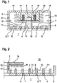
- 6 recesses 7 are provided instead of the flow openings. These have in plan view the same dimensions as the original flow openings 6, but do not extend over the entire height of the valve plate 5. So prevails in the recesses 7 of the pressure p 2 when the valve is closed, so that further on the sealing surface 9 of the valve disk 4, the pressure p 2 is applied, the recesses 7 are connected via at least one flow opening 6 with a reduced flow cross-section with the intake manifold 1 (see FIGS. 4 and 5 ). In the illustrated as a flow opening 6 serving circular bore of the diameter and thus the free flow cross section, for example, 1 mm.
- the free flow cross-section and the length l of the at least one flow opening 6 is to be selected such that a rapid pressure equalization takes place between the recess 7 serving as pressure equalization chamber and the intake tract 1, in order to produce a pressure or force compensation on the movable components in this way.
- the flow of the valve can be varied and adapted to customer requirements, without affecting the desired pressure or force balance on the moving components. To adapt the valve to the respective customer requirements can therefore be used largely the same components. It only need different valve plates 5 are provided with different flow openings 6.
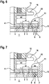
- FIGS. 6 and 7 show that - starting from a basic valve type according to the FIG. 6 -
- the free flow cross section of the radially inner flow opening 6 of the valve plate 5 at gelichzeitiger arrangement of a recess 7 according to the FIG. 7 can be reduced without changing the area ratio of the pressurized surfaces. It is essential that the in the FIGS. 6 and 7 as area A 3 designated surface of the armature 3 is approximately equal to the sum of the partial areas A 1 and A 2 of the valve disk 4.
Landscapes
- Engineering & Computer Science (AREA)
- Chemical & Material Sciences (AREA)
- Mechanical Engineering (AREA)
- General Engineering & Computer Science (AREA)
- Combustion & Propulsion (AREA)
- Chemical Kinetics & Catalysis (AREA)
- General Chemical & Material Sciences (AREA)
- Oil, Petroleum & Natural Gas (AREA)
- Analytical Chemistry (AREA)
- Physics & Mathematics (AREA)
- Electromagnetism (AREA)
- Magnetically Actuated Valves (AREA)
Claims (7)
- Electrovanne pour le dosage d'un fluide dans un système d'admission (1) d'un moteur, comprenant un module magnétique (2), un induit (3) coopérant avec le module magnétique (2) et un plateau de soupape (4) à mouvement alternatif connecté à l'induit (3) pour ouvrir et fermer au moins une ouverture d'écoulement (6) réalisée dans une plaque de soupape (5), l'ouverture d'écoulement (6) débouchant dans un évidement (7) d'une face frontale (8) de la plaque de soupape (5) tournée vers le plateau de soupape (4), et l'évidement (7) étant opposé à une face d'étanchéité (9) du plateau de soupape (4) pour étanchéifier l'évidement (7) par rapport à un espace de soupape (10),
caractérisée en ce que l'induit (3) et le plateau de soupape (4) sont essentiellement compensés en pression dans la position de fermeture. - Electrovanne selon la revendication 1,
caractérisée en ce que plusieurs ouvertures d'écoulement (6) débouchent dans l'évidement (7). - Electrovanne selon la revendication 1 ou 2,
caractérisée en ce que plusieurs évidements (7) sont réalisés dans la face frontale (8) de la plaque de soupape (5), en regard desquels est disposée la face d'étanchéité (9) du plateau de soupape (4) pour réaliser l'étanchéité par rapport à l'espace de soupape (10), chaque évidement (7) possédant de préférence, en vue de dessus, une forme en arc de cercle et la pluralité d'évidements (7) s'étendant en forme d'arc de cercle étant disposés concentriquement les uns par rapport aux autres. - Électrovanne selon l'une quelconque des revendications précédentes,
caractérisée en ce que le plateau de soupape (4) présente plusieurs ouvertures d'écoulement (11) en regard de la face frontale (8) de la plaque de soupape (5) pour réaliser l'étanchéité de l'espace de soupape (10) par rapport à l'évidement ou aux évidements (7) de la plaque de soupape (4). - Électrovanne selon l'une quelconque des revendications précédentes,
caractérisée en ce que pour réaliser un équilibre de pression dans la position de fermeture, l'induit (3) et le plateau de soupape (4) possèdent des faces (12, 13) en regard l'une de l'autre au niveau de l'espace de soupape (10), lesquelles ont essentiellement les mêmes dimensions. - Électrovanne selon l'une quelconque des revendications précédentes,
caractérisée en ce que l'induit (3) délimite, par le biais d'une face frontale (14), un espace de pression (15) qui est étanchéifié par rapport à l'espace de soupape (10) au moyen d'un élément d'étanchéité (16) et qui peut être connecté fluidiquement au système d'admission (1) par le biais d'alésages (17, 18) du plateau de soupape (4) et de la plaque de soupape (5). - Électrovanne selon la revendication 6,
caractérisée en ce que la face frontale (14) de l'induit (3) délimitant l'espace de pression (15) est essentiellement aussi grande que la face d'étanchéité (9) du plateau de soupape (4) qui peut être amenée en coïncidence avec l'évidement (7) ou avec les évidements (7) de la plaque de soupape (5), de telle sorte que l'induit (3) et le plateau de soupape (4) soient essentiellement équilibrés en pression dans la position de fermeture.
Applications Claiming Priority (1)
| Application Number | Priority Date | Filing Date | Title |
|---|---|---|---|
| DE102013212681.6A DE102013212681A1 (de) | 2013-06-28 | 2013-06-28 | Magnetventil und Verfahren zur Herstellung von Magnetventilen |
Publications (3)
| Publication Number | Publication Date |
|---|---|
| EP2818680A2 EP2818680A2 (fr) | 2014-12-31 |
| EP2818680A3 EP2818680A3 (fr) | 2016-01-27 |
| EP2818680B1 true EP2818680B1 (fr) | 2017-08-23 |
Family
ID=50976516
Family Applications (1)
| Application Number | Title | Priority Date | Filing Date |
|---|---|---|---|
| EP14173313.9A Active EP2818680B1 (fr) | 2013-06-28 | 2014-06-20 | Électrovanne et procédé de fabrication d'électrovannes |
Country Status (3)
| Country | Link |
|---|---|
| US (1) | US9644586B2 (fr) |
| EP (1) | EP2818680B1 (fr) |
| DE (1) | DE102013212681A1 (fr) |
Families Citing this family (11)
| Publication number | Priority date | Publication date | Assignee | Title |
|---|---|---|---|---|
| DE102013212681A1 (de) * | 2013-06-28 | 2014-12-31 | Robert Bosch Gmbh | Magnetventil und Verfahren zur Herstellung von Magnetventilen |
| US9453486B1 (en) | 2015-03-20 | 2016-09-27 | Continental Automotive Systems, Inc. | Gas direct injector with reduced leakage |
| EP3153693B1 (fr) | 2015-10-09 | 2018-07-18 | Continental Automotive GmbH | Injecteur de carburant |
| DE102016213168A1 (de) | 2016-07-19 | 2018-01-25 | Robert Bosch Gmbh | Ventil zum Dosieren von Fluiden |
| US10364897B2 (en) * | 2017-06-05 | 2019-07-30 | Vistadeltek, Llc | Control plate for a high conductance valve |
| US10458553B1 (en) | 2017-06-05 | 2019-10-29 | Vistadeltek, Llc | Control plate for a high conductive valve |
| US11248708B2 (en) | 2017-06-05 | 2022-02-15 | Illinois Tool Works Inc. | Control plate for a high conductance valve |
| DE102017212756A1 (de) * | 2017-07-25 | 2019-01-31 | Robert Bosch Gmbh | Dosierventil für ein gasförmiges Medium |
| WO2019029811A1 (fr) | 2017-08-10 | 2019-02-14 | Robert Bosch Gmbh | Soupape de dosage de fluides |
| DE102017220911A1 (de) * | 2017-11-23 | 2019-05-23 | Robert Bosch Gmbh | Gasinjektor mit verbesserten Einblaseigenschaften |
| CN118057059A (zh) * | 2022-11-18 | 2024-05-21 | Oppo广东移动通信有限公司 | 电磁阀、血压计及可穿戴式血压计 |
Family Cites Families (35)
| Publication number | Priority date | Publication date | Assignee | Title |
|---|---|---|---|---|
| US1695069A (en) * | 1925-10-14 | 1928-12-11 | Ingersoll Rand Co | Plate valve |
| US1971171A (en) * | 1931-03-20 | 1934-08-21 | Ingersoll Rand Co | Plate valve |
| US2525054A (en) * | 1945-04-19 | 1950-10-10 | Voss Johann Heinrich Hermann | Valve |
| US2838068A (en) * | 1951-02-10 | 1958-06-10 | Gen Controls Co | Electromagnetic valve |
| GB1076184A (en) * | 1963-05-01 | 1967-07-19 | Ass Eng Ltd | Fuel injectors for internal combustion engines |
| US3312241A (en) * | 1964-04-16 | 1967-04-04 | Westinghouse Electric Corp | Fluid control apparatus |
| GB1599525A (en) * | 1977-03-26 | 1981-10-07 | Lucas Industries Ltd | Fuel injection nozzle units |
| US4300595A (en) * | 1979-11-28 | 1981-11-17 | The Bendix Corporation | Solenoid control valve |
| US4947887A (en) * | 1981-10-16 | 1990-08-14 | Borg-Warner Corporation | Proportional solenoid valve |
| DE3228323A1 (de) * | 1982-07-29 | 1984-02-02 | Pierburg Gmbh & Co Kg, 4040 Neuss | Brennstoffeinspritzventil |
| US4515129A (en) * | 1983-06-10 | 1985-05-07 | General Motors Corporation | Edge discharge pulse fuel injector |
| US4483363A (en) * | 1983-09-21 | 1984-11-20 | Madoche Robert D | Compressor valve |
| JPS61142708A (ja) * | 1984-12-15 | 1986-06-30 | Diesel Kiki Co Ltd | 電磁アクチュエ−タ |
| US4681142A (en) * | 1985-11-07 | 1987-07-21 | The United States Of America As Represented By The Administrator Of The National Aeronautics And Space Administration | Self-compensating solenoid valve |
| GB8611950D0 (en) * | 1986-05-16 | 1986-06-25 | Lucas Ind Plc | Gasoline injector |
| US4718455A (en) * | 1986-11-05 | 1988-01-12 | Ingersoll-Rand Company | Plate-type fluid control valve |
| US4787418A (en) * | 1987-09-15 | 1988-11-29 | Colt Industries Inc. | Valve assembly and fuel metering apparatus |
| GB9217281D0 (en) * | 1992-08-14 | 1992-09-30 | Lucas Ind Plc | Fuel injector |
| US5398724A (en) * | 1993-06-28 | 1995-03-21 | Woodward Governor Company | High speed electrically actuated gaseous fuel admission valve |
| JP3305515B2 (ja) * | 1994-10-06 | 2002-07-22 | 日本エム・ケー・エス株式会社 | 流量制御弁 |
| SE9801588D0 (sv) * | 1998-05-05 | 1998-05-05 | Swiss Fed Inst Of Tech Zuerich | Electromagnetic valve for gaseous fluids |
| US6112765A (en) * | 1998-05-26 | 2000-09-05 | Caterpillar Inc. | Method and apparatus for monitoring operation of a gaseous fuel admission valve |
| AT412303B (de) * | 2000-04-18 | 2004-12-27 | Hoerbiger Ventilwerke Gmbh | Ventil |
| US6871803B1 (en) * | 2000-06-05 | 2005-03-29 | Fujikin Incorporated | Valve with an integral orifice |
| US6422198B1 (en) * | 2000-09-19 | 2002-07-23 | Delphi Technologies, Inc. | Pressure atomizer having multiple orifices and turbulent generation feature |
| DE102004012281A1 (de) * | 2003-03-14 | 2004-11-04 | Denso Corp., Kariya | Einfacher Aufbau eines Kraftstoffdruckreglers, der zum Minimieren eines Druckverlustes ausgelegt ist |
| DE10351205A1 (de) * | 2003-11-03 | 2005-06-02 | Robert Bosch Gmbh | Ventil zum Steuern eines Fluids |
| US7896028B2 (en) * | 2006-08-04 | 2011-03-01 | Fisher Controls International Llc | Flow restricted seat ring for pressure regulators |
| DE102007002841A1 (de) * | 2007-01-19 | 2008-07-24 | Robert Bosch Gmbh | Ventil zum Steuern eines gasförmigen Mediums |
| DE102007003213A1 (de) * | 2007-01-22 | 2008-07-24 | Robert Bosch Gmbh | Gas-Einblasventil |
| DE102007008901B4 (de) * | 2007-02-23 | 2008-10-16 | Compact Dynamics Gmbh | Fluid-Einspritzventil |
| US7669789B2 (en) * | 2007-08-29 | 2010-03-02 | Visteon Global Technologies, Inc. | Low pressure fuel injector nozzle |
| US8272399B2 (en) | 2008-06-13 | 2012-09-25 | Woodward, Inc. | Fluid admission system for providing a pressure-balanced valve |
| US8646479B2 (en) * | 2010-02-03 | 2014-02-11 | Kci Licensing, Inc. | Singulation of valves |
| DE102013212681A1 (de) * | 2013-06-28 | 2014-12-31 | Robert Bosch Gmbh | Magnetventil und Verfahren zur Herstellung von Magnetventilen |
-
2013
- 2013-06-28 DE DE102013212681.6A patent/DE102013212681A1/de not_active Withdrawn
-
2014
- 2014-06-20 EP EP14173313.9A patent/EP2818680B1/fr active Active
- 2014-06-30 US US14/318,724 patent/US9644586B2/en active Active
Non-Patent Citations (1)
| Title |
|---|
| None * |
Also Published As
| Publication number | Publication date |
|---|---|
| US20150001319A1 (en) | 2015-01-01 |
| EP2818680A3 (fr) | 2016-01-27 |
| US9644586B2 (en) | 2017-05-09 |
| EP2818680A2 (fr) | 2014-12-31 |
| DE102013212681A1 (de) | 2014-12-31 |
Similar Documents
| Publication | Publication Date | Title |
|---|---|---|
| EP2818680B1 (fr) | Électrovanne et procédé de fabrication d'électrovannes | |
| EP3161299B1 (fr) | Vanne à gaz | |
| DE102010032251A1 (de) | Rückschlagventil sowie hydraulisches Ventil mit einem eingebauten Rückschlagventil | |
| EP2516229B1 (fr) | Électrovanne et système d'aide à la conduite équipé de cette dernière | |
| DE102010028835A1 (de) | Kraftstoffinjektor | |
| EP2927439A1 (fr) | Soupape hydraulique pour un moteur oscillant d'un arbre à came | |
| EP3478957B1 (fr) | Soupape d'injection d'un carburant gazeux | |
| DE102008032133B4 (de) | Kraftstoffeinspritzvorrichtung | |
| DE102010000244A1 (de) | Brennstoffeinspritzvorrichtung | |
| EP1203153A1 (fr) | Systeme de soupape de commande destine a etre utilise dans un injecteur de carburant de moteurs a combustion interne | |
| DE102007032873A1 (de) | Regelventil | |
| DE102014207744A1 (de) | Ventileinheit für eine Steuervorrichtung zum Steuern eines fluidischen Antriebs, Steuervorrichtung zum Steuern eines fluidischen Antriebs und Verfahren zum Herstellen einer solchen Ventileinheit | |
| DE102014217441A1 (de) | Elektromagnetisch betätigbares Proportionalventil | |
| DE102007006872A1 (de) | Kugelsitzventil mit konturiertem Steuerstößel | |
| EP1319127B1 (fr) | Configuration de soupapes de distribution | |
| EP2466107B1 (fr) | Injecteur de carburant comportant une soupape de commande à équilibrage de pression | |
| DE102013212140A1 (de) | Steuerventil | |
| EP3577335B1 (fr) | Arrangement | |
| DE102019200940A1 (de) | Schnellschaltventil | |
| DE102017222501A1 (de) | Ventil zum Zumessen eines Fluids | |
| DE102011082666A1 (de) | Kraftstoffinjektor, insbesondere für ein Common-Rail-Einspritzsystem | |
| DE102004009460A1 (de) | Ventil | |
| DE102018004856B4 (de) | Verfahren zur Herstellung eines elektrofluidischen Sitzventil | |
| DE102009033458A1 (de) | Hochdruckventil für eine ventilgesteuerte Verdrängereinheit | |
| WO2007017303A1 (fr) | Soupape d'injection de carburant pour moteurs a combustion interne |
Legal Events
| Date | Code | Title | Description |
|---|---|---|---|
| PUAI | Public reference made under article 153(3) epc to a published international application that has entered the european phase |
Free format text: ORIGINAL CODE: 0009012 |
|
| 17P | Request for examination filed |
Effective date: 20140620 |
|
| AK | Designated contracting states |
Kind code of ref document: A2 Designated state(s): AL AT BE BG CH CY CZ DE DK EE ES FI FR GB GR HR HU IE IS IT LI LT LU LV MC MK MT NL NO PL PT RO RS SE SI SK SM TR |
|
| AX | Request for extension of the european patent |
Extension state: BA ME |
|
| PUAL | Search report despatched |
Free format text: ORIGINAL CODE: 0009013 |
|
| AK | Designated contracting states |
Kind code of ref document: A3 Designated state(s): AL AT BE BG CH CY CZ DE DK EE ES FI FR GB GR HR HU IE IS IT LI LT LU LV MC MK MT NL NO PL PT RO RS SE SI SK SM TR |
|
| AX | Request for extension of the european patent |
Extension state: BA ME |
|
| RIC1 | Information provided on ipc code assigned before grant |
Ipc: F02M 21/02 20060101AFI20151218BHEP Ipc: F16K 31/06 20060101ALI20151218BHEP |
|
| R17P | Request for examination filed (corrected) |
Effective date: 20160727 |
|
| RBV | Designated contracting states (corrected) |
Designated state(s): AL AT BE BG CH CY CZ DE DK EE ES FI FR GB GR HR HU IE IS IT LI LT LU LV MC MK MT NL NO PL PT RO RS SE SI SK SM TR |
|
| RIC1 | Information provided on ipc code assigned before grant |
Ipc: F16K 31/06 20060101ALI20161028BHEP Ipc: F02M 21/02 20060101AFI20161028BHEP |
|
| GRAP | Despatch of communication of intention to grant a patent |
Free format text: ORIGINAL CODE: EPIDOSNIGR1 |
|
| INTG | Intention to grant announced |
Effective date: 20170308 |
|
| GRAS | Grant fee paid |
Free format text: ORIGINAL CODE: EPIDOSNIGR3 |
|
| GRAA | (expected) grant |
Free format text: ORIGINAL CODE: 0009210 |
|
| AK | Designated contracting states |
Kind code of ref document: B1 Designated state(s): AL AT BE BG CH CY CZ DE DK EE ES FI FR GB GR HR HU IE IS IT LI LT LU LV MC MK MT NL NO PL PT RO RS SE SI SK SM TR |
|
| REG | Reference to a national code |
Ref country code: GB Ref legal event code: FG4D Free format text: NOT ENGLISH |
|
| REG | Reference to a national code |
Ref country code: CH Ref legal event code: EP |
|
| REG | Reference to a national code |
Ref country code: AT Ref legal event code: REF Ref document number: 921618 Country of ref document: AT Kind code of ref document: T Effective date: 20170915 |
|
| REG | Reference to a national code |
Ref country code: IE Ref legal event code: FG4D Free format text: LANGUAGE OF EP DOCUMENT: GERMAN |
|
| REG | Reference to a national code |
Ref country code: DE Ref legal event code: R096 Ref document number: 502014005133 Country of ref document: DE |
|
| REG | Reference to a national code |
Ref country code: NL Ref legal event code: FP |
|
| REG | Reference to a national code |
Ref country code: LT Ref legal event code: MG4D |
|
| PG25 | Lapsed in a contracting state [announced via postgrant information from national office to epo] |
Ref country code: LT Free format text: LAPSE BECAUSE OF FAILURE TO SUBMIT A TRANSLATION OF THE DESCRIPTION OR TO PAY THE FEE WITHIN THE PRESCRIBED TIME-LIMIT Effective date: 20170823 Ref country code: SE Free format text: LAPSE BECAUSE OF FAILURE TO SUBMIT A TRANSLATION OF THE DESCRIPTION OR TO PAY THE FEE WITHIN THE PRESCRIBED TIME-LIMIT Effective date: 20170823 Ref country code: HR Free format text: LAPSE BECAUSE OF FAILURE TO SUBMIT A TRANSLATION OF THE DESCRIPTION OR TO PAY THE FEE WITHIN THE PRESCRIBED TIME-LIMIT Effective date: 20170823 Ref country code: FI Free format text: LAPSE BECAUSE OF FAILURE TO SUBMIT A TRANSLATION OF THE DESCRIPTION OR TO PAY THE FEE WITHIN THE PRESCRIBED TIME-LIMIT Effective date: 20170823 Ref country code: NO Free format text: LAPSE BECAUSE OF FAILURE TO SUBMIT A TRANSLATION OF THE DESCRIPTION OR TO PAY THE FEE WITHIN THE PRESCRIBED TIME-LIMIT Effective date: 20171123 |
|
| PG25 | Lapsed in a contracting state [announced via postgrant information from national office to epo] |
Ref country code: GR Free format text: LAPSE BECAUSE OF FAILURE TO SUBMIT A TRANSLATION OF THE DESCRIPTION OR TO PAY THE FEE WITHIN THE PRESCRIBED TIME-LIMIT Effective date: 20171124 Ref country code: IS Free format text: LAPSE BECAUSE OF FAILURE TO SUBMIT A TRANSLATION OF THE DESCRIPTION OR TO PAY THE FEE WITHIN THE PRESCRIBED TIME-LIMIT Effective date: 20171223 Ref country code: RS Free format text: LAPSE BECAUSE OF FAILURE TO SUBMIT A TRANSLATION OF THE DESCRIPTION OR TO PAY THE FEE WITHIN THE PRESCRIBED TIME-LIMIT Effective date: 20170823 Ref country code: ES Free format text: LAPSE BECAUSE OF FAILURE TO SUBMIT A TRANSLATION OF THE DESCRIPTION OR TO PAY THE FEE WITHIN THE PRESCRIBED TIME-LIMIT Effective date: 20170823 Ref country code: LV Free format text: LAPSE BECAUSE OF FAILURE TO SUBMIT A TRANSLATION OF THE DESCRIPTION OR TO PAY THE FEE WITHIN THE PRESCRIBED TIME-LIMIT Effective date: 20170823 Ref country code: BG Free format text: LAPSE BECAUSE OF FAILURE TO SUBMIT A TRANSLATION OF THE DESCRIPTION OR TO PAY THE FEE WITHIN THE PRESCRIBED TIME-LIMIT Effective date: 20171123 Ref country code: PL Free format text: LAPSE BECAUSE OF FAILURE TO SUBMIT A TRANSLATION OF THE DESCRIPTION OR TO PAY THE FEE WITHIN THE PRESCRIBED TIME-LIMIT Effective date: 20170823 |
|
| PG25 | Lapsed in a contracting state [announced via postgrant information from national office to epo] |
Ref country code: RO Free format text: LAPSE BECAUSE OF FAILURE TO SUBMIT A TRANSLATION OF THE DESCRIPTION OR TO PAY THE FEE WITHIN THE PRESCRIBED TIME-LIMIT Effective date: 20170823 Ref country code: CZ Free format text: LAPSE BECAUSE OF FAILURE TO SUBMIT A TRANSLATION OF THE DESCRIPTION OR TO PAY THE FEE WITHIN THE PRESCRIBED TIME-LIMIT Effective date: 20170823 Ref country code: DK Free format text: LAPSE BECAUSE OF FAILURE TO SUBMIT A TRANSLATION OF THE DESCRIPTION OR TO PAY THE FEE WITHIN THE PRESCRIBED TIME-LIMIT Effective date: 20170823 |
|
| REG | Reference to a national code |
Ref country code: DE Ref legal event code: R097 Ref document number: 502014005133 Country of ref document: DE |
|
| PG25 | Lapsed in a contracting state [announced via postgrant information from national office to epo] |
Ref country code: EE Free format text: LAPSE BECAUSE OF FAILURE TO SUBMIT A TRANSLATION OF THE DESCRIPTION OR TO PAY THE FEE WITHIN THE PRESCRIBED TIME-LIMIT Effective date: 20170823 Ref country code: SK Free format text: LAPSE BECAUSE OF FAILURE TO SUBMIT A TRANSLATION OF THE DESCRIPTION OR TO PAY THE FEE WITHIN THE PRESCRIBED TIME-LIMIT Effective date: 20170823 Ref country code: SM Free format text: LAPSE BECAUSE OF FAILURE TO SUBMIT A TRANSLATION OF THE DESCRIPTION OR TO PAY THE FEE WITHIN THE PRESCRIBED TIME-LIMIT Effective date: 20170823 Ref country code: IT Free format text: LAPSE BECAUSE OF FAILURE TO SUBMIT A TRANSLATION OF THE DESCRIPTION OR TO PAY THE FEE WITHIN THE PRESCRIBED TIME-LIMIT Effective date: 20170823 |
|
| PLBE | No opposition filed within time limit |
Free format text: ORIGINAL CODE: 0009261 |
|
| STAA | Information on the status of an ep patent application or granted ep patent |
Free format text: STATUS: NO OPPOSITION FILED WITHIN TIME LIMIT |
|
| 26N | No opposition filed |
Effective date: 20180524 |
|
| PG25 | Lapsed in a contracting state [announced via postgrant information from national office to epo] |
Ref country code: SI Free format text: LAPSE BECAUSE OF FAILURE TO SUBMIT A TRANSLATION OF THE DESCRIPTION OR TO PAY THE FEE WITHIN THE PRESCRIBED TIME-LIMIT Effective date: 20170823 |
|
| PG25 | Lapsed in a contracting state [announced via postgrant information from national office to epo] |
Ref country code: MT Free format text: LAPSE BECAUSE OF FAILURE TO SUBMIT A TRANSLATION OF THE DESCRIPTION OR TO PAY THE FEE WITHIN THE PRESCRIBED TIME-LIMIT Effective date: 20170823 |
|
| REG | Reference to a national code |
Ref country code: CH Ref legal event code: PL |
|
| GBPC | Gb: european patent ceased through non-payment of renewal fee |
Effective date: 20180620 |
|
| REG | Reference to a national code |
Ref country code: BE Ref legal event code: MM Effective date: 20180630 |
|
| REG | Reference to a national code |
Ref country code: IE Ref legal event code: MM4A |
|
| PG25 | Lapsed in a contracting state [announced via postgrant information from national office to epo] |
Ref country code: MC Free format text: LAPSE BECAUSE OF FAILURE TO SUBMIT A TRANSLATION OF THE DESCRIPTION OR TO PAY THE FEE WITHIN THE PRESCRIBED TIME-LIMIT Effective date: 20170823 Ref country code: LU Free format text: LAPSE BECAUSE OF NON-PAYMENT OF DUE FEES Effective date: 20180620 |
|
| PG25 | Lapsed in a contracting state [announced via postgrant information from national office to epo] |
Ref country code: CH Free format text: LAPSE BECAUSE OF NON-PAYMENT OF DUE FEES Effective date: 20180630 Ref country code: LI Free format text: LAPSE BECAUSE OF NON-PAYMENT OF DUE FEES Effective date: 20180630 Ref country code: FR Free format text: LAPSE BECAUSE OF NON-PAYMENT OF DUE FEES Effective date: 20180630 Ref country code: IE Free format text: LAPSE BECAUSE OF NON-PAYMENT OF DUE FEES Effective date: 20180620 Ref country code: GB Free format text: LAPSE BECAUSE OF NON-PAYMENT OF DUE FEES Effective date: 20180620 |
|
| PG25 | Lapsed in a contracting state [announced via postgrant information from national office to epo] |
Ref country code: BE Free format text: LAPSE BECAUSE OF NON-PAYMENT OF DUE FEES Effective date: 20180630 |
|
| PG25 | Lapsed in a contracting state [announced via postgrant information from national office to epo] |
Ref country code: TR Free format text: LAPSE BECAUSE OF FAILURE TO SUBMIT A TRANSLATION OF THE DESCRIPTION OR TO PAY THE FEE WITHIN THE PRESCRIBED TIME-LIMIT Effective date: 20170823 |
|
| PG25 | Lapsed in a contracting state [announced via postgrant information from national office to epo] |
Ref country code: HU Free format text: LAPSE BECAUSE OF FAILURE TO SUBMIT A TRANSLATION OF THE DESCRIPTION OR TO PAY THE FEE WITHIN THE PRESCRIBED TIME-LIMIT; INVALID AB INITIO Effective date: 20140620 Ref country code: PT Free format text: LAPSE BECAUSE OF FAILURE TO SUBMIT A TRANSLATION OF THE DESCRIPTION OR TO PAY THE FEE WITHIN THE PRESCRIBED TIME-LIMIT Effective date: 20170823 |
|
| PG25 | Lapsed in a contracting state [announced via postgrant information from national office to epo] |
Ref country code: MK Free format text: LAPSE BECAUSE OF NON-PAYMENT OF DUE FEES Effective date: 20170823 Ref country code: CY Free format text: LAPSE BECAUSE OF FAILURE TO SUBMIT A TRANSLATION OF THE DESCRIPTION OR TO PAY THE FEE WITHIN THE PRESCRIBED TIME-LIMIT Effective date: 20170823 |
|
| PG25 | Lapsed in a contracting state [announced via postgrant information from national office to epo] |
Ref country code: AL Free format text: LAPSE BECAUSE OF FAILURE TO SUBMIT A TRANSLATION OF THE DESCRIPTION OR TO PAY THE FEE WITHIN THE PRESCRIBED TIME-LIMIT Effective date: 20170823 |
|
| PGFP | Annual fee paid to national office [announced via postgrant information from national office to epo] |
Ref country code: NL Payment date: 20200622 Year of fee payment: 7 |
|
| REG | Reference to a national code |
Ref country code: NL Ref legal event code: MM Effective date: 20210701 |
|
| PG25 | Lapsed in a contracting state [announced via postgrant information from national office to epo] |
Ref country code: NL Free format text: LAPSE BECAUSE OF NON-PAYMENT OF DUE FEES Effective date: 20210701 |
|
| PGFP | Annual fee paid to national office [announced via postgrant information from national office to epo] |
Ref country code: AT Payment date: 20230616 Year of fee payment: 10 |
|
| PGFP | Annual fee paid to national office [announced via postgrant information from national office to epo] |
Ref country code: DE Payment date: 20230817 Year of fee payment: 10 |