EP2818680B1 - Solenoid valve, and method for producing solenoid valves - Google Patents
Solenoid valve, and method for producing solenoid valves Download PDFInfo
- Publication number
- EP2818680B1 EP2818680B1 EP14173313.9A EP14173313A EP2818680B1 EP 2818680 B1 EP2818680 B1 EP 2818680B1 EP 14173313 A EP14173313 A EP 14173313A EP 2818680 B1 EP2818680 B1 EP 2818680B1
- Authority
- EP
- European Patent Office
- Prior art keywords
- valve
- armature
- pressure
- recess
- face
- Prior art date
- Legal status (The legal status is an assumption and is not a legal conclusion. Google has not performed a legal analysis and makes no representation as to the accuracy of the status listed.)
- Active
Links
- 238000004519 manufacturing process Methods 0.000 title description 6
- 238000007789 sealing Methods 0.000 claims description 24
- 239000012530 fluid Substances 0.000 claims description 4
- 238000011161 development Methods 0.000 description 3
- 230000018109 developmental process Effects 0.000 description 3
- 238000000034 method Methods 0.000 description 3
- 239000000446 fuel Substances 0.000 description 2
- 238000003860 storage Methods 0.000 description 2
- 230000006978 adaptation Effects 0.000 description 1
- 230000015572 biosynthetic process Effects 0.000 description 1
- 230000000694 effects Effects 0.000 description 1
Images

Classifications
-
- F—MECHANICAL ENGINEERING; LIGHTING; HEATING; WEAPONS; BLASTING
- F02—COMBUSTION ENGINES; HOT-GAS OR COMBUSTION-PRODUCT ENGINE PLANTS
- F02M—SUPPLYING COMBUSTION ENGINES IN GENERAL WITH COMBUSTIBLE MIXTURES OR CONSTITUENTS THEREOF
- F02M51/00—Fuel-injection apparatus characterised by being operated electrically
- F02M51/06—Injectors peculiar thereto with means directly operating the valve needle
- F02M51/061—Injectors peculiar thereto with means directly operating the valve needle using electromagnetic operating means
- F02M51/0625—Injectors peculiar thereto with means directly operating the valve needle using electromagnetic operating means characterised by arrangement of mobile armatures
- F02M51/0664—Injectors peculiar thereto with means directly operating the valve needle using electromagnetic operating means characterised by arrangement of mobile armatures having a cylindrically or partly cylindrically shaped armature, e.g. entering the winding; having a plate-shaped or undulated armature entering the winding
-
- F—MECHANICAL ENGINEERING; LIGHTING; HEATING; WEAPONS; BLASTING
- F02—COMBUSTION ENGINES; HOT-GAS OR COMBUSTION-PRODUCT ENGINE PLANTS
- F02M—SUPPLYING COMBUSTION ENGINES IN GENERAL WITH COMBUSTIBLE MIXTURES OR CONSTITUENTS THEREOF
- F02M21/00—Apparatus for supplying engines with non-liquid fuels, e.g. gaseous fuels stored in liquid form
- F02M21/02—Apparatus for supplying engines with non-liquid fuels, e.g. gaseous fuels stored in liquid form for gaseous fuels
- F02M21/0218—Details on the gaseous fuel supply system, e.g. tanks, valves, pipes, pumps, rails, injectors or mixers
- F02M21/0248—Injectors
- F02M21/0257—Details of the valve closing elements, e.g. valve seats, stems or arrangement of flow passages
- F02M21/026—Lift valves, i.e. stem operated valves
- F02M21/0263—Inwardly opening single or multi nozzle valves, e.g. needle valves
-
- B—PERFORMING OPERATIONS; TRANSPORTING
- B23—MACHINE TOOLS; METAL-WORKING NOT OTHERWISE PROVIDED FOR
- B23P—METAL-WORKING NOT OTHERWISE PROVIDED FOR; COMBINED OPERATIONS; UNIVERSAL MACHINE TOOLS
- B23P15/00—Making specific metal objects by operations not covered by a single other subclass or a group in this subclass
- B23P15/001—Making specific metal objects by operations not covered by a single other subclass or a group in this subclass valves or valve housings
-
- F—MECHANICAL ENGINEERING; LIGHTING; HEATING; WEAPONS; BLASTING
- F02—COMBUSTION ENGINES; HOT-GAS OR COMBUSTION-PRODUCT ENGINE PLANTS
- F02M—SUPPLYING COMBUSTION ENGINES IN GENERAL WITH COMBUSTIBLE MIXTURES OR CONSTITUENTS THEREOF
- F02M21/00—Apparatus for supplying engines with non-liquid fuels, e.g. gaseous fuels stored in liquid form
- F02M21/02—Apparatus for supplying engines with non-liquid fuels, e.g. gaseous fuels stored in liquid form for gaseous fuels
- F02M21/0218—Details on the gaseous fuel supply system, e.g. tanks, valves, pipes, pumps, rails, injectors or mixers
- F02M21/0248—Injectors
- F02M21/0251—Details of actuators therefor
- F02M21/0254—Electric actuators, e.g. solenoid or piezoelectric
-
- F—MECHANICAL ENGINEERING; LIGHTING; HEATING; WEAPONS; BLASTING
- F02—COMBUSTION ENGINES; HOT-GAS OR COMBUSTION-PRODUCT ENGINE PLANTS
- F02M—SUPPLYING COMBUSTION ENGINES IN GENERAL WITH COMBUSTIBLE MIXTURES OR CONSTITUENTS THEREOF
- F02M21/00—Apparatus for supplying engines with non-liquid fuels, e.g. gaseous fuels stored in liquid form
- F02M21/02—Apparatus for supplying engines with non-liquid fuels, e.g. gaseous fuels stored in liquid form for gaseous fuels
- F02M21/0218—Details on the gaseous fuel supply system, e.g. tanks, valves, pipes, pumps, rails, injectors or mixers
- F02M21/0248—Injectors
- F02M21/0257—Details of the valve closing elements, e.g. valve seats, stems or arrangement of flow passages
- F02M21/0272—Ball valves; Plate valves; Valves having deformable or flexible parts, e.g. membranes; Rotatable valves
-
- F—MECHANICAL ENGINEERING; LIGHTING; HEATING; WEAPONS; BLASTING
- F02—COMBUSTION ENGINES; HOT-GAS OR COMBUSTION-PRODUCT ENGINE PLANTS
- F02M—SUPPLYING COMBUSTION ENGINES IN GENERAL WITH COMBUSTIBLE MIXTURES OR CONSTITUENTS THEREOF
- F02M61/00—Fuel-injectors not provided for in groups F02M39/00 - F02M57/00 or F02M67/00
- F02M61/16—Details not provided for in, or of interest apart from, the apparatus of groups F02M61/02 - F02M61/14
- F02M61/18—Injection nozzles, e.g. having valve seats; Details of valve member seated ends, not otherwise provided for
- F02M61/1853—Orifice plates
-
- F—MECHANICAL ENGINEERING; LIGHTING; HEATING; WEAPONS; BLASTING
- F16—ENGINEERING ELEMENTS AND UNITS; GENERAL MEASURES FOR PRODUCING AND MAINTAINING EFFECTIVE FUNCTIONING OF MACHINES OR INSTALLATIONS; THERMAL INSULATION IN GENERAL
- F16K—VALVES; TAPS; COCKS; ACTUATING-FLOATS; DEVICES FOR VENTING OR AERATING
- F16K31/00—Actuating devices; Operating means; Releasing devices
- F16K31/02—Actuating devices; Operating means; Releasing devices electric; magnetic
- F16K31/06—Actuating devices; Operating means; Releasing devices electric; magnetic using a magnet, e.g. diaphragm valves, cutting off by means of a liquid
- F16K31/0686—Braking, pressure equilibration, shock absorbing
- F16K31/0693—Pressure equilibration of the armature
-
- Y—GENERAL TAGGING OF NEW TECHNOLOGICAL DEVELOPMENTS; GENERAL TAGGING OF CROSS-SECTIONAL TECHNOLOGIES SPANNING OVER SEVERAL SECTIONS OF THE IPC; TECHNICAL SUBJECTS COVERED BY FORMER USPC CROSS-REFERENCE ART COLLECTIONS [XRACs] AND DIGESTS
- Y02—TECHNOLOGIES OR APPLICATIONS FOR MITIGATION OR ADAPTATION AGAINST CLIMATE CHANGE
- Y02T—CLIMATE CHANGE MITIGATION TECHNOLOGIES RELATED TO TRANSPORTATION
- Y02T10/00—Road transport of goods or passengers
- Y02T10/10—Internal combustion engine [ICE] based vehicles
- Y02T10/30—Use of alternative fuels, e.g. biofuels
-
- Y—GENERAL TAGGING OF NEW TECHNOLOGICAL DEVELOPMENTS; GENERAL TAGGING OF CROSS-SECTIONAL TECHNOLOGIES SPANNING OVER SEVERAL SECTIONS OF THE IPC; TECHNICAL SUBJECTS COVERED BY FORMER USPC CROSS-REFERENCE ART COLLECTIONS [XRACs] AND DIGESTS
- Y10—TECHNICAL SUBJECTS COVERED BY FORMER USPC
- Y10T—TECHNICAL SUBJECTS COVERED BY FORMER US CLASSIFICATION
- Y10T29/00—Metal working
- Y10T29/49—Method of mechanical manufacture
- Y10T29/49405—Valve or choke making
- Y10T29/49409—Valve seat forming
Definitions
- the invention relates to a solenoid valve for metering a fluid into an intake tract of an engine having the features of the preamble of claim 1. Furthermore, the invention relates to a method for producing a series of solenoid valves, which differ in terms of their maximum flow.
- a solenoid valve as a metering valve is in WO 2005/043016 disclosed.
- the specified solenoid valve should in particular be used as a metering valve for a gaseous medium, preferably for a gaseous fuel.
- the focus is also on the use in large engines.
- the mass flows usually required for large engines up to 3000 kg / h require relatively large opening cross sections of the metering valves used herein.
- small dosing must be represented via the metering valves, which requires a high switching dynamics. To realize this, it is necessary to keep the switching forces as low as possible. As a rule, pressure-balanced valves are therefore used.
- a pressure balanced electromagnetically actuated valve for use in large engines is an example of the patent US 8,272,399 B2 out. It comprises a magnet assembly, a liftable armature cooperating with the magnet assembly, and a liftable valve disc connected to the armature for releasing and closing a plurality of slot-like flow openings in a valve plate.
- the liftable valve plate also has slot-like flow openings, between which a sealing surface remains, which can be brought to seal a valve space with respect to a lying outside the valve pressure chamber in register with the flow openings of the valve plate.
- valve Pressure chamber The outside of the valve Pressure chamber is connected via a central pressure equalization bore, which passes through the valve plate and the valve plate, with a pressure equalization chamber, so that in the pressure equalization chamber and in the pressure chamber, the same pressure prevails, which acts on the armature in the closing direction and acting on the valve disk in the opening direction pressure force ,
- the pressure prevailing in the valve chamber is present at the armature and at the valve disk, which pressure produces a pressure force acting on the valve disk in the closing direction and a force acting on the armature in the opening direction.
- the pressurized surfaces are chosen such that the movable components, namely the armature and the valve disk, are substantially pressure-balanced in the closed position. The pressure compensation has the consequence that the required switching forces are significantly reduced.
- pressure-balanced valves have the disadvantage that change with the change in the flow cross sections of the provided in the valve plate flow openings and the relevant areas for pressure equalization.
- a change in the flow cross sections may be caused, for example, by customer-specific requirements.
- the moving components and / or the magnet assembly must be redesigned and matched to restore pressure equalization.
- the present invention has for its object to provide a solenoid valve for dosing a fluid that allows the concept in a simple manner to adapt to customer-specific requirements.
- the solenoid valve proposed for metering a fluid into an intake manifold of an engine includes a magnet assembly, an armature cooperating with the magnet assembly, and an armature connected to the armature assembly.
- liftable valve disc for releasing and closing at least one formed in a valve plate flow-through.
- the flow-through opening opens into a recess of an end face of the valve plate facing the valve disk.
- the recess faces a sealing surface of the valve disk for sealing the recess with respect to a valve space.
- the sealing surface of the valve disk which can be brought into overlap with the recess of the valve plate, bears the pressure p 2 prevailing in the intake tract, which pressure is smaller than a pressure p 1 prevailing in the valve chamber.
- the size of the overlap region determines the pressure force resulting from the pressure p 2 and acting on the valve disk in the opening direction. This applies regardless of how large the flow cross section of the at least one opening into the recess flow opening, so that it is arbitrary selectable.
- the flow cross-section of the at least one flow-through opening which fluidly connects the recess to the intake tract, merely has to allow a sufficiently fast pressure equalization between the intake tract and the recess. Because it is important to ensure that the pressure equalization between the pressure in the recess and the pressure in the intake tract has taken place before the next opening of the valve.
- the opening cross-section or valve flow can be easily adapted to the respective customer-specific requirements.
- the same components can be used, so that only the exchange of the valve plate allows a large spread of the opening cross-sections or flow rates. The exchange of the valve plate remains without influence on any pressure induced by the pressurized surfaces on the armature and the valve plate.
- the valve can be designed, for example, for a mass flow of 3000 kg / h.
- the flow can be reduced in different stages, without having to adjust the other active components.
- the valve housing, the magnet assembly, the armature and / or the valve disc can remain unchanged.
- a plurality of recesses are formed in the end face of the valve plate, which faces the sealing surface of the valve disk for sealing against the valve space.
- At least one throughflow opening for fluidic connection with the intake tract opens into each recess.
- each recess in the plan view has a circular arc-shaped course and the plurality of circular arc-shaped recesses are arranged concentrically with each other.
- Such recesses can be produced in a simple manner.
- valve disk has a plurality of flow-through openings which lie opposite the end face of the valve plate for sealing the valve space with respect to the recess or recesses of the valve plate.
- the flow-through openings of the valve disk preferably also extend in the shape of a circular arc and are arranged concentrically with respect to one another, wherein the flow-through openings of the valve disk are each arranged offset relative to the recesses of the valve plate. This ensures that in the closed position, the sealing surface of the valve plate seals the valve chamber to the outside.
- the armature and the valve disk in the closed position are substantially pressure balanced.
- the switching of the valve thus requires low forces that can be displayed even at high pressures and / or mass flows by means of a simple magnet assembly.
- the armature and the valve disk have mutually opposite surfaces on the valve space, which are substantially equal in size. Since the surfaces of the armature and of the valve disk are located opposite the valve chamber, the pressure p 1 of the valve chamber is present in each case. By the surfaces are at least approximately the same size, the armature and the valve disk are acted upon in the opposite direction by a substantially equal compressive force, so that the forces are largely balanced.
- the pressurized surfaces on the armature and / or on the valve disk can also be composed of several partial surfaces.
- the anchor limits over an end face a pressure chamber which is sealed by means of a sealing element with respect to the valve chamber and is fluidically connectable via bores of the valve disk and the valve plate with the intake tract.
- the holes of the valve disk and the valve plate are able to produce a pressure equalization between the pressure chamber and the intake in this way.
- the same pressure prevails in the pressure chamber as in the intake tract. This results in a force acting on the armature in the closing direction compressive force, which is able to compensate for an opening force resulting from the pressure of the intake and acting on the sealing surface of the valve disk.
- the pressure chamber limiting end face of the armature is substantially the same size as the sealing surface of the valve disk, which can be brought into overlap with the recess or the recesses of the valve plate, so that the armature and the valve disk in the closed position are substantially pressure balanced.
- a method for producing a series of solenoid valves which differ in terms of their maximum flow is also proposed.
- the procedure is for each Solenoid valve, a valve plate of a plurality of held valve plates, which differ in the number, arrangement, shape and / or size of at least one flow-through, selected to determine the maximum flow and installed with otherwise substantially the same components.
- manufacturing and storage costs can be reduced, since substantially the same components are used.
- Only the valve plate is selected for adaptation of the solenoid valve to the respective customer-specific requirements of a plurality of valve plates, which differ substantially only in relation to the flow cross-section of the at least one flow opening.
- the valve plates are formed largely the same. All valve plates can thus be installed with the same housing, the same valve plate, the same armature and / or the same magnetic assembly.
- valve plates are preferably reserved and used, which have at least one recess in an end face into which the throughflow opening opens. In this way, the choice of the valve plate has no effect on any set pressure or force balance on the pressurized surfaces of the moving components.
- the representation of the FIG. 1 is a preferred embodiment of a solenoid valve according to the invention can be seen.
- the solenoid valve comprises a valve plate 5, which also serves as a housing, in which a valve chamber 10 is formed.
- the valve plate 5 For filling the valve chamber 10 with a gaseous medium, in particular with a gaseous fuel, the valve plate 5 has a plurality of radial bores 21.
- the gaseous medium supplied to the valve space 10 via the radial bores 21 has a pressure p 1 when it enters the valve space 10. Outside the valve, in an intake 1, there is a pressure p 2 , which is smaller than the pressure p 1 . In the open position of the valve thus the gaseous medium flows into the intake tract. 1
- the valve plate 5 has a plurality of flow-through openings 6, via which the gaseous medium from the valve chamber 10 enters the intake tract 1 when the valve is open.
- a liftable valve disk 4 is received in the housing, which is fixedly connected to an armature 3.
- the armature 3 including the valve plate 4 can be actuated.
- the armature 3 and the valve plate 4 are pulled in the direction of the coil 20, wherein the valve plate 4 lifts off from serving as a valve seat face 8 of the valve plate 5 and the flow openings 6 releases.
- the magnet coil 20 is surrounded by a magnetic core 19 of the magnet assembly 2, on which a sealing element 16 is attached.
- the sealing element 16 is also attached to the formation of a pressure chamber 15 on the armature 3, so that the sealing element 16 at the same time causes a seal of the pressure chamber 15 relative to the valve chamber 10.
- the pressure chamber 15 Via a central bore 17 in the valve plate 4 or armature 3 and a central bore 18 in the valve plate 5, the pressure chamber 15 is fluidly connected to the intake manifold 1. Accordingly, the pressure p 2 also prevails in the pressure chamber 15. Since the armature 3 with an end face 14 delimits the pressure chamber 15 in the axial direction, the pressure p 2 is applied to the armature 3 on the pressure chamber side.
- Valve chamber side is located on a surface 12 of the armature 3, the pressure p 1 at.
- the surface 12 is located on the valve chamber 10, the surface 13 of the valve plate 4 opposite.
- the surface 13 is composed of several individual surfaces, since the valve disk 4 is penetrated by a plurality of flow openings 11.
- the number, the arrangement, the shape and the size of the flow openings 11 is matched to the flow openings 6 of the valve plate 5, so that the flow openings 11 of the valve disk 4, the end face 8 of the valve plate 5 and the flow openings 6 of the valve disk 4, a sealing surface. 9 of the valve plate 4 are opposite.
- the flow-through openings 11 of the valve disk 4 have an arc-shaped course and are arranged concentrically with one another (see FIG. 3 ).
- the flow openings 6 of the valve plate 5 partially coincide with recesses 7, which are formed in the end face 8 of the valve plate 5 and thus the sealing surface 9 are opposite. Radially inside lying the recesses 7, however, are not carried out continuously, but form a pressure compensation chamber, which is fluidly connected via flow openings 6 with a reduced flow cross-section with the intake manifold 1.
- the surface 13 is composed of several partial surfaces, the same size, the forces acting thereon on the armature 3 and the valve plate 4 are balanced.
- a complete balance of pressure or force on the moving components is produced, in particular, if the areas acted upon by the pressure p 2 are also of the same size.
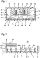
- 6 recesses 7 are provided instead of the flow openings. These have in plan view the same dimensions as the original flow openings 6, but do not extend over the entire height of the valve plate 5. So prevails in the recesses 7 of the pressure p 2 when the valve is closed, so that further on the sealing surface 9 of the valve disk 4, the pressure p 2 is applied, the recesses 7 are connected via at least one flow opening 6 with a reduced flow cross-section with the intake manifold 1 (see FIGS. 4 and 5 ). In the illustrated as a flow opening 6 serving circular bore of the diameter and thus the free flow cross section, for example, 1 mm.
- the free flow cross-section and the length l of the at least one flow opening 6 is to be selected such that a rapid pressure equalization takes place between the recess 7 serving as pressure equalization chamber and the intake tract 1, in order to produce a pressure or force compensation on the movable components in this way.
- the flow of the valve can be varied and adapted to customer requirements, without affecting the desired pressure or force balance on the moving components. To adapt the valve to the respective customer requirements can therefore be used largely the same components. It only need different valve plates 5 are provided with different flow openings 6.
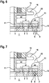
- FIGS. 6 and 7 show that - starting from a basic valve type according to the FIG. 6 -
- the free flow cross section of the radially inner flow opening 6 of the valve plate 5 at gelichzeitiger arrangement of a recess 7 according to the FIG. 7 can be reduced without changing the area ratio of the pressurized surfaces. It is essential that the in the FIGS. 6 and 7 as area A 3 designated surface of the armature 3 is approximately equal to the sum of the partial areas A 1 and A 2 of the valve disk 4.
Description
Die Erfindung betrifft ein Magnetventil zum Eindosieren eines Fluids in einen Ansaugtrakt eines Motors mit den Merkmalen des Oberbegriffs des Anspruchs 1. Ferner betrifft die Erfindung ein Verfahren zur Herstellung einer Reihe von Magnetventilen, die sich hinsichtlich ihres maximalen Durchflusses unterscheiden.The invention relates to a solenoid valve for metering a fluid into an intake tract of an engine having the features of the preamble of
Ein Beispiel für den Einsatz ein Magnetventil als Dosierventil wird in
Ein druckausgeglichenes elektromagnetisch betätigbares Ventil für den Einsatz in Großmotoren geht beispielhaft aus der Patentschrift
Derartige druckausgeglichene Ventile weisen jedoch den Nachteil auf, dass sich mit Veränderung der Strömungsquerschnitte der in der Ventilplatte vorgesehenen Durchströmöffnungen auch die für den Druckausgleich relevanten Flächen verändern. Eine Veränderung der Strömungsquerschnitte kann beispielsweise durch kundenspezifische Anforderungen bedingt sein. In der Folge müssen die beweglichen Bauteile und/oder die Magnetbaugruppe neu ausgelegt und aufeinander abgestimmt werden, um den Druckausgleich wieder herzustellen.However, such pressure-balanced valves have the disadvantage that change with the change in the flow cross sections of the provided in the valve plate flow openings and the relevant areas for pressure equalization. A change in the flow cross sections may be caused, for example, by customer-specific requirements. As a result, the moving components and / or the magnet assembly must be redesigned and matched to restore pressure equalization.
Ausgehend von dem vorstehend genannten Stand der Technik liegt daher der vorliegenden Erfindung die Aufgabe zugrunde, ein Magnetventil zum Eindosieren eines Fluids anzugeben, das vom Konzept her in einfacher Weise eine Anpassung an kundenspezifische Anforderungen ermöglicht.Based on the above-mentioned prior art, therefore, the present invention has for its object to provide a solenoid valve for dosing a fluid that allows the concept in a simple manner to adapt to customer-specific requirements.
Zur Lösung der Aufgabe wird das Magnetventil mit den Merkmalen des Anspruchs 1 vorgeschlagen. Vorteilhafte Weiterbildungen der Erfindung sind in den jeweiligen Unteransprüchen angegeben. Ferner wird ein Verfahren zur Herstellung eines solchen Magnetventils vorgeschlagen.To solve the problem, the solenoid valve with the features of
Das zum Eindosieren eines Fluids in einen Ansaugtrakt eines Motors vorgeschlagene Magnetventil umfasst eine Magnetbaugruppe, einen mit der Magnetbaugruppe zusammenwirkenden Anker und einen mit dem Anker verbundenen, hubbeweglichen Ventilteller zum Freigeben und Verschließen wenigstens einer in einer Ventilplatte ausgebildeten Durchströmöffnung. Erfindungsgemäß mündet die Durchströmöffnung in eine Ausnehmung einer dem Ventilteller zugewandten Stirnfläche der Ventilplatte. Ferner erfindungsgemäß liegt der Ausnehmung eine Dichtfläche des Ventiltellers zur Abdichtung der Ausnehmung gegenüber einem Ventilraum gegenüber. In Schließstellung des Ventils liegt demnach an der in Überdeckung mit der Ausnehmung der Ventilplatte bringbaren Dichtfläche des Ventiltellers der im Ansaugtrakt herrschende Druck p2 an, der kleiner als ein im Ventilraum herrschender Druck p1 ist. Die Größe des Überdeckungsbereichs bestimmt dabei die aus dem Druck p2 resultierende und auf den Ventilteller in Öffnungsrichtung wirkende Druckkraft. Dies gilt unabhängig davon, wie groß der Strömungsquerschnitt der wenigstens einen in die Ausnehmung mündenden Durchströmöffnung ist, so dass dieser beliebig wählbar ist. Der Strömungsquerschnitt der wenigstens einen Durchströmöffnung, welche die Ausnehmung mit dem Ansaugtrakt fluidisch verbindet, muss lediglich einen ausreichend schnellen Druckausgleich zwischen dem Ansaugtrakt und der Ausnehmung ermöglichen. Denn es gilt sicherzustellen, dass der Druckausgleich zwischen dem Druck in der Ausnehmung und dem Druck im Ansaugtrakt vor dem nächsten Öffnen des Ventils erfolgt ist.The solenoid valve proposed for metering a fluid into an intake manifold of an engine includes a magnet assembly, an armature cooperating with the magnet assembly, and an armature connected to the armature assembly. liftable valve disc for releasing and closing at least one formed in a valve plate flow-through. According to the invention, the flow-through opening opens into a recess of an end face of the valve plate facing the valve disk. Furthermore, according to the invention, the recess faces a sealing surface of the valve disk for sealing the recess with respect to a valve space. Accordingly, in the closed position of the valve, the sealing surface of the valve disk, which can be brought into overlap with the recess of the valve plate, bears the pressure p 2 prevailing in the intake tract, which pressure is smaller than a pressure p 1 prevailing in the valve chamber. The size of the overlap region determines the pressure force resulting from the pressure p 2 and acting on the valve disk in the opening direction. This applies regardless of how large the flow cross section of the at least one opening into the recess flow opening, so that it is arbitrary selectable. The flow cross-section of the at least one flow-through opening, which fluidly connects the recess to the intake tract, merely has to allow a sufficiently fast pressure equalization between the intake tract and the recess. Because it is important to ensure that the pressure equalization between the pressure in the recess and the pressure in the intake tract has taken place before the next opening of the valve.
Indem der Strömungsquerschnitt der in die Ausnehmung mündenden Durchströmöffnung der Ventilplatte beliebig wählbar ist, kann der Öffnungsquerschnitt bzw. Ventildurchfluss in einfacher Weise an die jeweiligen kundenspezifischen Anforderungen angepasst werden. Zur Darstellung einer Vielzahl verschiedener Ventile mit unterschiedlichen Öffnungsquerschnitten bzw. Durchflüssen bedarf es demnach lediglich der Vorhaltung einer entsprechenden Vielzahl an Ventilplatten, die sich im Hinblick auf den Strömungsquerschnitt der wenigstens einen Durchströmöffnung unterscheiden. Im Übrigen können die gleichen Bauteile verwendet werden, so dass allein der Austausch der Ventilplatte eine große Spreizung der Öffnungsquerschnitte bzw. Durchflüsse ermöglicht. Der Austausch der Ventilplatte bleibt dabei ohne Einfluss auf einen etwaigen über die druckbeaufschlagten Flächen am Anker und am Ventilteller bewirkten Druckausgleich.By the flow cross section of the opening into the recess flow opening of the valve plate is arbitrary, the opening cross-section or valve flow can be easily adapted to the respective customer-specific requirements. To represent a plurality of different valves with different opening cross-sections or flow rates, it is therefore only necessary to provide a corresponding multiplicity of valve plates which differ with regard to the flow cross-section of the at least one flow-through opening. Incidentally, the same components can be used, so that only the exchange of the valve plate allows a large spread of the opening cross-sections or flow rates. The exchange of the valve plate remains without influence on any pressure induced by the pressurized surfaces on the armature and the valve plate.
In einer Grundauslegung kann das Ventil beispielsweise für einen Massenstrom von 3000kg/h ausgelegt werden. In Abhängigkeit von der Anzahl, der Anordnung, der Form und/oder der Größe der wenigstens einen Durchströmöffnung der jeweils eingesetzten Ventilplatte kann der Durchfluss in verschiedenen Stufen reduziert werden, ohne dabei die anderen Wirkkomponenten anpassen zu müssen. Insbesondere können das Ventilgehäuse, die Magnetbaugruppe, der Anker und/oder der Ventilteller unverändert bleiben. Mit einem Ventil-Grundtyp, der möglichst viele gleiche Teile umfasst, lassen sich somit viele verschiedene Ventile realisieren, um den jeweiligen Kundenanforderungen gerecht zu werden. Es müssen lediglich verschiedene Ventilplatten vorgehalten werden. Dadurch bleiben Entwicklungs-, Herstellungs- und Lagerhaltungskosten gering.In a basic design, the valve can be designed, for example, for a mass flow of 3000 kg / h. Depending on the number, the arrangement, the shape and / or size of the at least one flow opening of the valve plate used in each case, the flow can be reduced in different stages, without having to adjust the other active components. In particular, the valve housing, the magnet assembly, the armature and / or the valve disc can remain unchanged. With a basic valve type that includes as many identical parts as possible, many different valves can be realized in order to meet the respective customer requirements. It only need to be kept different valve plates. As a result, development, manufacturing and storage costs remain low.
Gemäß einer bevorzugten Ausführungsform der Erfindung münden mehrere Durchströmöffnungen in die Ausnehmung. Dies erleichtert den Druckausgleich zwischen dem Ansaugtrakt und der Ausnehmung nach dem Schließen des Ventils, so dass in kürzester Zeit der im Ansaugtrakt herrschende Druck p2 auch in der Ausnehmung der Ventilplatte herrscht bzw. an der Dichtfläche des Ventiltellers anliegt, welche die Ausnehmung gegenüber dem Ventilraum abdichtet.According to a preferred embodiment of the invention, several flow-through openings open into the recess. This facilitates the pressure equalization between the intake tract and the recess after closing the valve, so that in the shortest time prevailing in the intake pressure p 2 prevails in the recess of the valve plate and rests against the sealing surface of the valve disk, which the recess relative to the valve chamber seals.
Gemäß einer weiteren bevorzugten Ausführungsform der Erfindung sind mehrere Ausnehmungen in der Stirnfläche der Ventilplatte ausgebildet, denen die Dichtfläche des Ventiltellers zur Abdichtung gegenüber dem Ventilraum gegenüber liegt. In jede Ausnehmung mündet dabei wenigstens eine Durchströmöffnung zur fluidischen Verbindung mit dem Ansaugtrakt. Vorzugsweise besitzt jede Ausnehmung in der Draufsicht einen kreisbogenförmigen Verlauf und die mehreren kreisbogenförmig verlaufenden Ausnehmungen sind konzentrisch zueinander angeordnet. Derartige Ausnehmungen sind in einfacher Weise herstellbar.According to a further preferred embodiment of the invention, a plurality of recesses are formed in the end face of the valve plate, which faces the sealing surface of the valve disk for sealing against the valve space. At least one throughflow opening for fluidic connection with the intake tract opens into each recess. Preferably, each recess in the plan view has a circular arc-shaped course and the plurality of circular arc-shaped recesses are arranged concentrically with each other. Such recesses can be produced in a simple manner.
Des Weiteren wird vorgeschlagen, dass der Ventilteller mehrere Durchströmöffnungen besitzt, die der Stirnfläche der Ventilplatte zur Abdichtung des Ventilraums gegenüber der oder den Ausnehmungen der Ventilplatte gegenüber liegen. Die Durchströmöffnungen des Ventiltellers verlaufen vorzugsweise ebenfalls kreisbogenförmig und sind konzentrisch zueinander angeordnet, wobei die Durchströmöffnungen des Ventiltellers jeweils versetzt zu den Ausnehmungen der Ventilplatte angeordnet sind. Dadurch ist gewährleistet, dass in Schließstellung die Dichtfläche des Ventiltellers den Ventilraum nach außen hin abdichtet.Furthermore, it is proposed that the valve disk has a plurality of flow-through openings which lie opposite the end face of the valve plate for sealing the valve space with respect to the recess or recesses of the valve plate. The flow-through openings of the valve disk preferably also extend in the shape of a circular arc and are arranged concentrically with respect to one another, wherein the flow-through openings of the valve disk are each arranged offset relative to the recesses of the valve plate. This ensures that in the closed position, the sealing surface of the valve plate seals the valve chamber to the outside.
Vorteilhafterweise sind der Anker und der Ventilteller in Schließstellung im Wesentlichen druckausgeglichen. Das Schalten des Ventils erfordert somit geringe Kräfte, die selbst bei großen Drücken und/oder Massenströmen mittels einer einfachen Magnetbaugruppe darstellbar sind.Advantageously, the armature and the valve disk in the closed position are substantially pressure balanced. The switching of the valve thus requires low forces that can be displayed even at high pressures and / or mass flows by means of a simple magnet assembly.
Zur Realisierung eines Druckausgleichs in Schließstellung wird vorgeschlagen, dass der Anker und der Ventilteller einander am Ventilraum gegenüberliegende Flächen besitzen, die im Wesentlichen gleich groß sind. Da sich die Flächen des Ankers und des Ventiltellers am Ventilraum gegenüber liegen, liegt hier jeweils der Druck p1 des Ventilraums an. Indem die Flächen zumindest in etwa gleich groß sind, werden der Anker und der Ventilteller in entgegengesetzter Richtung von einer im Wesentlichen gleich großen Druckkraft beaufschlagt, so dass die Kräfte weitgehend ausgeglichen sind. Die druckbeaufschlagten Flächen am Anker und/oder am Ventilteller können sich dabei auch aus mehreren Teilflächen zusammensetzen.To realize a pressure equalization in the closed position, it is proposed that the armature and the valve disk have mutually opposite surfaces on the valve space, which are substantially equal in size. Since the surfaces of the armature and of the valve disk are located opposite the valve chamber, the pressure p 1 of the valve chamber is present in each case. By the surfaces are at least approximately the same size, the armature and the valve disk are acted upon in the opposite direction by a substantially equal compressive force, so that the forces are largely balanced. The pressurized surfaces on the armature and / or on the valve disk can also be composed of several partial surfaces.
Bevorzugt begrenzt der Anker über eine Stirnfläche einen Druckraum, der mittels eines Dichtelements gegenüber dem Ventilraum abgedichtet und über Bohrungen des Ventiltellers und der Ventilplatte mit dem Ansaugtrakt fluidisch verbindbar ist. Die Bohrungen des Ventiltellers und der Ventilplatte vermögen auf diese Weise einen Druckausgleich zwischen dem Druckraum und dem Ansaugtrakt herzustellen. Im Betrieb des Ventils herrscht demnach im Druckraum der gleiche Druck wie im Ansaugtrakt. Hieraus resultiert eine auf den Anker in Schließrichtung wirkende Druckkraft, die eine aus dem Druck des Ansaugtraktes resultierende und auf die Dichtfläche des Ventiltellers wirkende Öffnungskraft auszugleichen vermag.Preferably, the anchor limits over an end face a pressure chamber which is sealed by means of a sealing element with respect to the valve chamber and is fluidically connectable via bores of the valve disk and the valve plate with the intake tract. The holes of the valve disk and the valve plate are able to produce a pressure equalization between the pressure chamber and the intake in this way. During operation of the valve, the same pressure prevails in the pressure chamber as in the intake tract. This results in a force acting on the armature in the closing direction compressive force, which is able to compensate for an opening force resulting from the pressure of the intake and acting on the sealing surface of the valve disk.
Vorteilhafterweise ist die den Druckraum begrenzende Stirnfläche des Ankers im Wesentlichen gleich groß wie die Dichtfläche des Ventiltellers, die in Überdeckung mit der Ausnehmung bzw. den Ausnehmungen der Ventilplatte bringbar ist, so dass der Anker und der Ventilteller in Schließstellung im Wesentlichen druckausgeglichen sind.Advantageously, the pressure chamber limiting end face of the armature is substantially the same size as the sealing surface of the valve disk, which can be brought into overlap with the recess or the recesses of the valve plate, so that the armature and the valve disk in the closed position are substantially pressure balanced.
Zur Lösung der eingangs genannten Aufgabe wird ferner ein Verfahren zur Herstellung einer Reihe von Magnetventilen, die sich hinsichtlich ihres maximalen Durchflusses unterscheiden, vorgeschlagen. Bei dem Verfahren wird für jedes Magnetventil eine Ventilplatte aus mehreren vorgehaltenen Ventilplatten, die sich hinsichtlich der Anzahl, Anordnung, Form und/oder Größe wenigstens einer Durchströmöffnung unterscheiden, zur Festlegung des maximalen Durchflusses ausgewählt und mit ansonsten im Wesentlichen gleichen Bauteilen verbaut. Durch Einsatz des erfindungsgemäßen Verfahrens können Entwicklungs-, Herstellungs- und Lagerhaltungskosten reduziert werden, da im Wesentlichen gleiche Bauteile verwendet werden. Lediglich die Ventilplatte wird zur Anpassung des Magnetventils an die jeweiligen kundenspezifischen Anforderungen aus einer Vielzahl von Ventilplatten ausgewählt, die sich im Wesentlichen jedoch nur in Bezug auf den Strömungsquerschnitt der wenigstens einen Durchströmöffnung unterscheiden. Im Übrigen sind die Ventilplatten weitgehend gleich ausgebildet. Sämtliche Ventilplatten können somit mit dem gleichen Gehäuse, dem gleichen Ventilteller, dem gleichen Anker und/oder der gleichen Magnetbaugruppe verbaut werden.To solve the object mentioned above, a method for producing a series of solenoid valves, which differ in terms of their maximum flow is also proposed. The procedure is for each Solenoid valve, a valve plate of a plurality of held valve plates, which differ in the number, arrangement, shape and / or size of at least one flow-through, selected to determine the maximum flow and installed with otherwise substantially the same components. By using the method according to the invention development, manufacturing and storage costs can be reduced, since substantially the same components are used. Only the valve plate is selected for adaptation of the solenoid valve to the respective customer-specific requirements of a plurality of valve plates, which differ substantially only in relation to the flow cross-section of the at least one flow opening. Incidentally, the valve plates are formed largely the same. All valve plates can thus be installed with the same housing, the same valve plate, the same armature and / or the same magnetic assembly.
Bevorzugt werden bei dem Verfahren Ventilplatten vorgehalten und verwendet, die in einer Stirnfläche wenigstens eine Ausnehmung besitzen, in welche die Durchströmöffnung mündet. Auf diese Weise hat die Wahl der Ventilplatte keinen Einfluss auf einen etwaigen eingestellten Druck- bzw. Kräfteausgleich an den druckbeaufschlagten Flächen der beweglichen Bauteile.In the method, valve plates are preferably reserved and used, which have at least one recess in an end face into which the throughflow opening opens. In this way, the choice of the valve plate has no effect on any set pressure or force balance on the pressurized surfaces of the moving components.
Bevorzugte Ausführungsformen eines erfindungsgemäßen Magnetventils werden nachfolgend anhand der beigefügten Figuren näher beschrieben. Diese zeigen:
Figur 1- einen schematischen Längsschnitt durch ein erfindungsgemäßes Magnetventil gemäß einer bevorzugten Ausführungsform,
Figur 2- einen schematischen Längsschnitt in vergrößerter Darstellung zur Erläuterung des Druck- bzw. Kräfteausgleichs an den beweglichen Bauteilen eines erfindungsgemäßen Magnetventils,
Figur 3- eine teilweise Draufsicht auf einen Ventilteller eines erfindungsgemäßen Magnetventils,
Figur 4- eine teilweise Draufsicht auf eine Ventilplatte eines erfindungsgemäßen Magnetventils im Bereich einer Ausnehmung,
Figur 5- einen schematischen Querschnitt in vergrößerter Darstellung durch eine Ventilplatte und einen Ventilteller eines erfindungsgemäßen Magnetventils im Bereich einer Ausnehmung und einer Durchströmöffnung,
Figur 6- einen schematischen Längsschnitt durch ein bekanntes Magnetventil und
Figur 7- einen schematische Längsschnitt durch ein erfindungsgemäßes Magnetventil.
- FIG. 1
- a schematic longitudinal section through a solenoid valve according to the invention according to a preferred embodiment,
- FIG. 2
- a schematic longitudinal section in an enlarged view for explaining the pressure or force balance on the movable components of a solenoid valve according to the invention,
- FIG. 3
- a partial plan view of a valve disc of a solenoid valve according to the invention,
- FIG. 4
- a partial plan view of a valve plate of a solenoid valve according to the invention in the region of a recess,
- FIG. 5
- a schematic cross-section in an enlarged view through a valve plate and a valve disk of a solenoid valve according to the invention in the region of a recess and a flow-through,
- FIG. 6
- a schematic longitudinal section through a known solenoid valve and
- FIG. 7
- a schematic longitudinal section through an inventive solenoid valve.
Der Darstellung der
Die Ventilplatte 5 weist mehrere Durchströmöffnungen 6 auf, über welche das gasförmige Medium aus dem Ventilraum 10 in den Ansaugtrakt 1 gelangt, wenn das Ventil geöffnet ist. Zum Freigeben und Verschließen der Durchströmöffnungen 6 ist im Gehäuse ein hubbeweglicher Ventilteller 4 aufgenommen, der mit einem Anker 3 fest verbunden ist. Über eine ferner im Gehäuse aufgenommene Magnetbaugruppe 2 ist der Anker 3 einschließlich des Ventiltellers 4 betätigbar. Denn bei Bestromung einer Magnetspule 20 der Magnetbaugruppe 2 werden der Anker 3 und der Ventilteller 4 in Richtung der Spule 20 gezogen, wobei der Ventilteller 4 von einer als Ventilsitz dienenden Stirnfläche 8 der Ventilplatte 5 abhebt und die Durchströmöffnungen 6 freigibt. Die Magnetspule 20 ist von einem Magnetkern 19 der Magnetbaugruppe 2 umgeben, an dem ein Dichtelement 16 befestigt ist. Das Dichtelement 16 ist zur Ausbildung eines Druckraums 15 ferner am Anker 3 befestigt, so dass das Dichtelement 16 zugleich eine Abdichtung des Druckraums 15 gegenüber dem Ventilraum 10 bewirkt. Über eine zentrale Bohrung 17 im Ventilteller 4 bzw. Anker 3 und eine zentrale Bohrung 18 in der Ventilplatte 5 ist der Druckraum 15 mit dem Ansaugtrakt 1 fluidisch verbunden. Im Druckraum 15 herrscht demnach ebenfalls der Druck p2. Da der Anker 3 mit einer Stirnfläche 14 den Druckraum 15 in axialer Richtung begrenzt, liegt am Anker 3 druckraumseitig der Druck p2 an. Ventilraumseitig liegt an einer Fläche 12 des Ankers 3 der Druck p1 an. Der Fläche 12 liegt am Ventilraum 10 die Fläche 13 des Ventiltellers 4 gegenüber. Die Fläche 13 setzt sich dabei aus mehreren Einzelflächen zusammen, da der Ventilteller 4 von mehreren Durchströmöffnungen 11 durchsetzt wird. Die Anzahl, die Anordnung, die Form und die Größe der Durchströmöffnungen 11 ist dabei auf die der Durchströmöffnungen 6 der Ventilplatte 5 abgestimmt, so dass den Durchströmöffnungen 11 des Ventiltellers 4 die Stirnfläche 8 der Ventilplatte 5 und den Durchströmöffnungen 6 des Ventiltellers 4 eine Dichtfläche 9 des Ventiltellers 4 gegenüber liegen. Vorliegend weisen die Durchströmöffnungen 11 des Ventiltellers 4 einen kreisbogenförmigen Verlauf auf und sind konzentrisch zueinander angeordnet (siehe
Die Durchströmöffnungen 6 der Ventilplatte 5 fallen teilweise mit Ausnehmungen 7 zusammen, die in der Stirnfläche 8 der Ventilplatte 5 ausgebildet sind und somit der Dichtfläche 9 gegenüber liegen. Radial innen liegend sind die Ausnehmungen 7 jedoch nicht durchgehend ausgeführt, sondern bilden einen Druckausgleichsraum aus, der über Durchströmöffnungen 6 mit reduziertem Strömungsquerschnitt fluidisch mit dem Ansaugtrakt 1 verbunden ist. Werden nunmehr - wie in der
Um dieses Flächenverhältnis nicht zu verändern, wenn der Strömungsquerschnitt einzelner Durchströmöffnungen 6 in der Ventilplatte 5 reduziert wird, werden anstelle der Durchströmöffnungen 6 Ausnehmungen 7 vorgesehen. Diese weisen in der Draufsicht die gleichen Abmessungen wie die ursprünglichen Durchströmungsöffnungen 6 auf, erstrecken sich jedoch nicht über die ganze Höhe der Ventilplatte 5. Damit in den Ausnehmungen 7 der Druck p2 vorherrscht, wenn das Ventil geschlossen ist, so dass weiterhin an der Dichtfläche 9 des Ventiltellers 4 der Druck p2 anliegt, sind die Ausnehmungen 7 über wenigstens eine Durchströmöffnung 6 mit reduziertem Strömungsquerschnitt mit dem Ansaugtrakt 1 verbunden (siehe
Sofern die Abmessungen der Ausnehmung 7 in der Draufsicht auf die Ventilplatte 5 unverändert bleiben, kann der freie Strömungsquerschnitt der in die Ausnehmung 7 mündenden Durchströmöffnung 6 beliebig geändert werden. Damit kann der Durchfluss des Ventils variiert und an kundenspezifische Anforderungen angepasst werden, ohne dass dies Auswirkungen auf den angestrebten Druck- bzw. Kräfteausgleich an den beweglichen Bauteilen hat. Zur Anpassung des Ventils an die jeweiligen Kundenanforderungen können demnach weitgehend gleiche Bauteile verwendet werden. Es müssen lediglich verschiedene Ventilplatten 5 mit verschiedenen Durchströmungsöffnungen 6 vorgehalten werden.If the dimensions of the
Die Gegenüberstellung der
Claims (7)
- Solenoid valve for metering a fluid into an intake section (1) of an engine, comprising a magnet assembly (2), an armature (3) which interacts with the magnet assembly (2), and a valve head (4) with a reciprocating movement which is connected to the armature (3) for opening and closing at least one throughflow opening (6) which is configured in a valve plate (5), the throughflow opening (6) opening into a recess (7) of an end face (8) of the valve plate (5), which end face (8) faces the valve head (4), and a sealing face (9) of the valve head (4) lying opposite the recess (7) in order to seal the recess (7) with respect to a valve space (10), characterized in that the armature (3) and the valve head (4) are substantially pressure-equalized in the closed position.
- Solenoid valve according to Claim 1, characterized in that a plurality of throughflow openings (6) open into the recess (7).
- Solenoid valve according to Claim 1 or 2, characterized in that a plurality of recesses (7) are configured in the end face (8) of the valve plate (5), the sealing face (9) of the valve head (4) lying opposite the said recesses (7) in order to seal them with respect to the valve space (10), each recess (7) preferably having an arcuate profile in plan view, and the plurality of recesses (7) which run in an arcuate manner being arranged concentrically with respect to one another.
- Solenoid valve according to one of the preceding claims, characterized in that the valve head (4) has a plurality of throughflow openings (11) which lie opposite the end face (8) of the valve plate (5) in order to seal the valve space (10) with respect to the recess or recesses (7) of the valve plate (4).
- Solenoid valve according to one of the preceding claims, characterized in that, in order to achieve pressure equalization in the closed position, the armature (3) and the valve head (4) have faces (12, 13) which lie opposite one another on the valve space (10) and are of substantially identical size.
- Solenoid valve according to one of the preceding claims, characterized in that the armature (3) delimits a pressure space (15) via an end face (14), which pressure space (15) is sealed with respect to the valve space (10) by means of a sealing element (16) and can be connected fluidically to the intake section (1) via bores (17, 18) of the valve head (4) and the valve plate (5).
- Solenoid valve according to Claim 6, characterized in that that end face (14) of the armature (3) which delimits the pressure space (15) is of substantially identical size to the sealing face (9) of the valve head (4), which sealing face (9) can be brought into congruence with the recess (7) or the recesses (7) of the valve plate (5), with the result that the armature (3) and the valve head (4) are substantially pressure-equalized in the closed position.
Applications Claiming Priority (1)
| Application Number | Priority Date | Filing Date | Title |
|---|---|---|---|
| DE102013212681.6A DE102013212681A1 (en) | 2013-06-28 | 2013-06-28 | Solenoid valve and method of manufacturing solenoid valves |
Publications (3)
| Publication Number | Publication Date |
|---|---|
| EP2818680A2 EP2818680A2 (en) | 2014-12-31 |
| EP2818680A3 EP2818680A3 (en) | 2016-01-27 |
| EP2818680B1 true EP2818680B1 (en) | 2017-08-23 |
Family
ID=50976516
Family Applications (1)
| Application Number | Title | Priority Date | Filing Date |
|---|---|---|---|
| EP14173313.9A Active EP2818680B1 (en) | 2013-06-28 | 2014-06-20 | Solenoid valve, and method for producing solenoid valves |
Country Status (3)
| Country | Link |
|---|---|
| US (1) | US9644586B2 (en) |
| EP (1) | EP2818680B1 (en) |
| DE (1) | DE102013212681A1 (en) |
Families Citing this family (10)
| Publication number | Priority date | Publication date | Assignee | Title |
|---|---|---|---|---|
| DE102013212681A1 (en) * | 2013-06-28 | 2014-12-31 | Robert Bosch Gmbh | Solenoid valve and method of manufacturing solenoid valves |
| US9453486B1 (en) | 2015-03-20 | 2016-09-27 | Continental Automotive Systems, Inc. | Gas direct injector with reduced leakage |
| EP3153693B1 (en) * | 2015-10-09 | 2018-07-18 | Continental Automotive GmbH | Fuel injector |
| DE102016213168A1 (en) | 2016-07-19 | 2018-01-25 | Robert Bosch Gmbh | Valve for dosing fluids |
| US10458553B1 (en) | 2017-06-05 | 2019-10-29 | Vistadeltek, Llc | Control plate for a high conductive valve |
| US11248708B2 (en) | 2017-06-05 | 2022-02-15 | Illinois Tool Works Inc. | Control plate for a high conductance valve |
| US10364897B2 (en) * | 2017-06-05 | 2019-07-30 | Vistadeltek, Llc | Control plate for a high conductance valve |
| DE102017212756A1 (en) * | 2017-07-25 | 2019-01-31 | Robert Bosch Gmbh | Dosing valve for a gaseous medium |
| WO2019029811A1 (en) | 2017-08-10 | 2019-02-14 | Robert Bosch Gmbh | Valve for metering fluids |
| DE102017220911A1 (en) * | 2017-11-23 | 2019-05-23 | Robert Bosch Gmbh | Gas injector with improved injection properties |
Family Cites Families (35)
| Publication number | Priority date | Publication date | Assignee | Title |
|---|---|---|---|---|
| US1695069A (en) * | 1925-10-14 | 1928-12-11 | Ingersoll Rand Co | Plate valve |
| US1971171A (en) * | 1931-03-20 | 1934-08-21 | Ingersoll Rand Co | Plate valve |
| US2525054A (en) * | 1945-04-19 | 1950-10-10 | Voss Johann Heinrich Hermann | Valve |
| US2838068A (en) * | 1951-02-10 | 1958-06-10 | Gen Controls Co | Electromagnetic valve |
| GB1076184A (en) * | 1963-05-01 | 1967-07-19 | Ass Eng Ltd | Fuel injectors for internal combustion engines |
| US3312241A (en) * | 1964-04-16 | 1967-04-04 | Westinghouse Electric Corp | Fluid control apparatus |
| GB1599525A (en) * | 1977-03-26 | 1981-10-07 | Lucas Industries Ltd | Fuel injection nozzle units |
| US4300595A (en) * | 1979-11-28 | 1981-11-17 | The Bendix Corporation | Solenoid control valve |
| US4947887A (en) * | 1981-10-16 | 1990-08-14 | Borg-Warner Corporation | Proportional solenoid valve |
| DE3228323A1 (en) * | 1982-07-29 | 1984-02-02 | Pierburg Gmbh & Co Kg, 4040 Neuss | FUEL INJECTION VALVE |
| US4515129A (en) * | 1983-06-10 | 1985-05-07 | General Motors Corporation | Edge discharge pulse fuel injector |
| US4483363A (en) * | 1983-09-21 | 1984-11-20 | Madoche Robert D | Compressor valve |
| JPS61142708A (en) * | 1984-12-15 | 1986-06-30 | Diesel Kiki Co Ltd | Electromagnetic actuator |
| US4681142A (en) * | 1985-11-07 | 1987-07-21 | The United States Of America As Represented By The Administrator Of The National Aeronautics And Space Administration | Self-compensating solenoid valve |
| GB8611950D0 (en) * | 1986-05-16 | 1986-06-25 | Lucas Ind Plc | Gasoline injector |
| US4718455A (en) * | 1986-11-05 | 1988-01-12 | Ingersoll-Rand Company | Plate-type fluid control valve |
| US4787418A (en) * | 1987-09-15 | 1988-11-29 | Colt Industries Inc. | Valve assembly and fuel metering apparatus |
| GB9217281D0 (en) * | 1992-08-14 | 1992-09-30 | Lucas Ind Plc | Fuel injector |
| US5398724A (en) * | 1993-06-28 | 1995-03-21 | Woodward Governor Company | High speed electrically actuated gaseous fuel admission valve |
| JP3305515B2 (en) * | 1994-10-06 | 2002-07-22 | 日本エム・ケー・エス株式会社 | Flow control valve |
| SE9801588D0 (en) * | 1998-05-05 | 1998-05-05 | Swiss Fed Inst Of Tech Zuerich | Electromagnetic valve for gaseous fluids |
| US6112765A (en) * | 1998-05-26 | 2000-09-05 | Caterpillar Inc. | Method and apparatus for monitoring operation of a gaseous fuel admission valve |
| AT412303B (en) * | 2000-04-18 | 2004-12-27 | Hoerbiger Ventilwerke Gmbh | VALVE |
| CA2381193C (en) * | 2000-06-05 | 2005-08-23 | Fujikin Incorporated | Valve with an integral orifice |
| US6422198B1 (en) * | 2000-09-19 | 2002-07-23 | Delphi Technologies, Inc. | Pressure atomizer having multiple orifices and turbulent generation feature |
| DE102004012281A1 (en) * | 2003-03-14 | 2004-11-04 | Denso Corp., Kariya | Simple design of a fuel pressure regulator that is designed to minimize pressure loss |
| DE10351205A1 (en) * | 2003-11-03 | 2005-06-02 | Robert Bosch Gmbh | Valve for controlling a fluid |
| US7896028B2 (en) * | 2006-08-04 | 2011-03-01 | Fisher Controls International Llc | Flow restricted seat ring for pressure regulators |
| DE102007002841A1 (en) * | 2007-01-19 | 2008-07-24 | Robert Bosch Gmbh | Valve for controlling e.g. gaseous fuel, has valve seat arranged in housing, and sealing element including aperture and arranged at valve unit, to open and close passage opening of housing, and fixed at valve unit and valve seat |
| DE102007003213A1 (en) * | 2007-01-22 | 2008-07-24 | Robert Bosch Gmbh | Gas-injecting valve for injecting gaseous medium, particularly for injecting gaseous fuel into combustion chamber of internal-combustion engine of motor vehicle, has valve seat element with passage opening and it is unlocked and locked |
| DE102007008901B4 (en) * | 2007-02-23 | 2008-10-16 | Compact Dynamics Gmbh | Fluid injection valve |
| US7669789B2 (en) * | 2007-08-29 | 2010-03-02 | Visteon Global Technologies, Inc. | Low pressure fuel injector nozzle |
| US8272399B2 (en) | 2008-06-13 | 2012-09-25 | Woodward, Inc. | Fluid admission system for providing a pressure-balanced valve |
| US8646479B2 (en) * | 2010-02-03 | 2014-02-11 | Kci Licensing, Inc. | Singulation of valves |
| DE102013212681A1 (en) * | 2013-06-28 | 2014-12-31 | Robert Bosch Gmbh | Solenoid valve and method of manufacturing solenoid valves |
-
2013
- 2013-06-28 DE DE102013212681.6A patent/DE102013212681A1/en not_active Withdrawn
-
2014
- 2014-06-20 EP EP14173313.9A patent/EP2818680B1/en active Active
- 2014-06-30 US US14/318,724 patent/US9644586B2/en active Active
Non-Patent Citations (1)
| Title |
|---|
| None * |
Also Published As
| Publication number | Publication date |
|---|---|
| EP2818680A2 (en) | 2014-12-31 |
| US9644586B2 (en) | 2017-05-09 |
| DE102013212681A1 (en) | 2014-12-31 |
| EP2818680A3 (en) | 2016-01-27 |
| US20150001319A1 (en) | 2015-01-01 |
Similar Documents
| Publication | Publication Date | Title |
|---|---|---|
| EP2818680B1 (en) | Solenoid valve, and method for producing solenoid valves | |
| EP3161299B1 (en) | Gas valve | |
| DE102010032251A1 (en) | Check valve and hydraulic valve with built-in check valve | |
| DE202009016447U1 (en) | Fluidic control | |
| DE102010028835A1 (en) | fuel injector | |
| EP2927439A1 (en) | Hydraulic valve for a pivoting engine adjuster of a camshaft | |
| EP3478957B1 (en) | Valve for injecting gaseous fuel | |
| DE102008032133B4 (en) | Fuel injector | |
| WO2011076469A1 (en) | Magnetic valve and driver assistance device comprising said type of magnetic valve | |
| DE102010000244A1 (en) | Fuel injection device | |
| EP1203153A1 (en) | Control valve system used in a fuel injector for internal combustion engines | |
| DE102007032873A1 (en) | Control valve has at least one cut-out in valve seat and/or in valve piston that is fully covered in valve closed position and at least partly exposed in valve open position | |
| DE102014207744A1 (en) | Valve unit for a control device for controlling a fluidic drive, control device for controlling a fluidic drive and method for producing such a valve unit | |
| DE102014217441A1 (en) | Electromagnetically actuated proportional valve | |
| DE102007006872A1 (en) | Ball seat valve with contoured control ram | |
| EP1319127B1 (en) | Valve configuration for control valves | |
| EP2466107B1 (en) | Fuel injector with pressure-equalised control valve | |
| DE102013212140A1 (en) | control valve | |
| EP3577335B1 (en) | Arrangement | |
| DE102019200940A1 (en) | Fast switching valve | |
| DE102017222501A1 (en) | Valve for metering a fluid | |
| DE102011082666A1 (en) | Fuel injector, particularly for common-rail-injection system, has nozzle needle, which closes nozzle hole assembly in nozzle body in closed position, where nozzle needle is arranged in high-pressure chamber in nozzle body | |
| DE102004009460A1 (en) | Valve | |
| DE102018004856B4 (en) | Process for manufacturing an electro-fluidic seat valve | |
| DE102009033458A1 (en) | Pilot-controlled high pressure valve for radial or axial piston machine, has pilot pressure chamber discharged over pilot valve, and pressure medium connection provided between pilot pressure chamber and high pressure chamber |
Legal Events
| Date | Code | Title | Description |
|---|---|---|---|
| PUAI | Public reference made under article 153(3) epc to a published international application that has entered the european phase |
Free format text: ORIGINAL CODE: 0009012 |
|
| 17P | Request for examination filed |
Effective date: 20140620 |
|
| AK | Designated contracting states |
Kind code of ref document: A2 Designated state(s): AL AT BE BG CH CY CZ DE DK EE ES FI FR GB GR HR HU IE IS IT LI LT LU LV MC MK MT NL NO PL PT RO RS SE SI SK SM TR |
|
| AX | Request for extension of the european patent |
Extension state: BA ME |
|
| PUAL | Search report despatched |
Free format text: ORIGINAL CODE: 0009013 |
|
| AK | Designated contracting states |
Kind code of ref document: A3 Designated state(s): AL AT BE BG CH CY CZ DE DK EE ES FI FR GB GR HR HU IE IS IT LI LT LU LV MC MK MT NL NO PL PT RO RS SE SI SK SM TR |
|
| AX | Request for extension of the european patent |
Extension state: BA ME |
|
| RIC1 | Information provided on ipc code assigned before grant |
Ipc: F02M 21/02 20060101AFI20151218BHEP Ipc: F16K 31/06 20060101ALI20151218BHEP |
|
| R17P | Request for examination filed (corrected) |
Effective date: 20160727 |
|
| RBV | Designated contracting states (corrected) |
Designated state(s): AL AT BE BG CH CY CZ DE DK EE ES FI FR GB GR HR HU IE IS IT LI LT LU LV MC MK MT NL NO PL PT RO RS SE SI SK SM TR |
|
| RIC1 | Information provided on ipc code assigned before grant |
Ipc: F16K 31/06 20060101ALI20161028BHEP Ipc: F02M 21/02 20060101AFI20161028BHEP |
|
| GRAP | Despatch of communication of intention to grant a patent |
Free format text: ORIGINAL CODE: EPIDOSNIGR1 |
|
| INTG | Intention to grant announced |
Effective date: 20170308 |
|
| GRAS | Grant fee paid |
Free format text: ORIGINAL CODE: EPIDOSNIGR3 |
|
| GRAA | (expected) grant |
Free format text: ORIGINAL CODE: 0009210 |
|
| AK | Designated contracting states |
Kind code of ref document: B1 Designated state(s): AL AT BE BG CH CY CZ DE DK EE ES FI FR GB GR HR HU IE IS IT LI LT LU LV MC MK MT NL NO PL PT RO RS SE SI SK SM TR |
|
| REG | Reference to a national code |
Ref country code: GB Ref legal event code: FG4D Free format text: NOT ENGLISH |
|
| REG | Reference to a national code |
Ref country code: CH Ref legal event code: EP |
|
| REG | Reference to a national code |
Ref country code: AT Ref legal event code: REF Ref document number: 921618 Country of ref document: AT Kind code of ref document: T Effective date: 20170915 |
|
| REG | Reference to a national code |
Ref country code: IE Ref legal event code: FG4D Free format text: LANGUAGE OF EP DOCUMENT: GERMAN |
|
| REG | Reference to a national code |
Ref country code: DE Ref legal event code: R096 Ref document number: 502014005133 Country of ref document: DE |
|
| REG | Reference to a national code |
Ref country code: NL Ref legal event code: FP |
|
| REG | Reference to a national code |
Ref country code: LT Ref legal event code: MG4D |
|
| PG25 | Lapsed in a contracting state [announced via postgrant information from national office to epo] |
Ref country code: LT Free format text: LAPSE BECAUSE OF FAILURE TO SUBMIT A TRANSLATION OF THE DESCRIPTION OR TO PAY THE FEE WITHIN THE PRESCRIBED TIME-LIMIT Effective date: 20170823 Ref country code: SE Free format text: LAPSE BECAUSE OF FAILURE TO SUBMIT A TRANSLATION OF THE DESCRIPTION OR TO PAY THE FEE WITHIN THE PRESCRIBED TIME-LIMIT Effective date: 20170823 Ref country code: HR Free format text: LAPSE BECAUSE OF FAILURE TO SUBMIT A TRANSLATION OF THE DESCRIPTION OR TO PAY THE FEE WITHIN THE PRESCRIBED TIME-LIMIT Effective date: 20170823 Ref country code: FI Free format text: LAPSE BECAUSE OF FAILURE TO SUBMIT A TRANSLATION OF THE DESCRIPTION OR TO PAY THE FEE WITHIN THE PRESCRIBED TIME-LIMIT Effective date: 20170823 Ref country code: NO Free format text: LAPSE BECAUSE OF FAILURE TO SUBMIT A TRANSLATION OF THE DESCRIPTION OR TO PAY THE FEE WITHIN THE PRESCRIBED TIME-LIMIT Effective date: 20171123 |
|
| PG25 | Lapsed in a contracting state [announced via postgrant information from national office to epo] |
Ref country code: GR Free format text: LAPSE BECAUSE OF FAILURE TO SUBMIT A TRANSLATION OF THE DESCRIPTION OR TO PAY THE FEE WITHIN THE PRESCRIBED TIME-LIMIT Effective date: 20171124 Ref country code: IS Free format text: LAPSE BECAUSE OF FAILURE TO SUBMIT A TRANSLATION OF THE DESCRIPTION OR TO PAY THE FEE WITHIN THE PRESCRIBED TIME-LIMIT Effective date: 20171223 Ref country code: RS Free format text: LAPSE BECAUSE OF FAILURE TO SUBMIT A TRANSLATION OF THE DESCRIPTION OR TO PAY THE FEE WITHIN THE PRESCRIBED TIME-LIMIT Effective date: 20170823 Ref country code: ES Free format text: LAPSE BECAUSE OF FAILURE TO SUBMIT A TRANSLATION OF THE DESCRIPTION OR TO PAY THE FEE WITHIN THE PRESCRIBED TIME-LIMIT Effective date: 20170823 Ref country code: LV Free format text: LAPSE BECAUSE OF FAILURE TO SUBMIT A TRANSLATION OF THE DESCRIPTION OR TO PAY THE FEE WITHIN THE PRESCRIBED TIME-LIMIT Effective date: 20170823 Ref country code: BG Free format text: LAPSE BECAUSE OF FAILURE TO SUBMIT A TRANSLATION OF THE DESCRIPTION OR TO PAY THE FEE WITHIN THE PRESCRIBED TIME-LIMIT Effective date: 20171123 Ref country code: PL Free format text: LAPSE BECAUSE OF FAILURE TO SUBMIT A TRANSLATION OF THE DESCRIPTION OR TO PAY THE FEE WITHIN THE PRESCRIBED TIME-LIMIT Effective date: 20170823 |
|
| PG25 | Lapsed in a contracting state [announced via postgrant information from national office to epo] |
Ref country code: RO Free format text: LAPSE BECAUSE OF FAILURE TO SUBMIT A TRANSLATION OF THE DESCRIPTION OR TO PAY THE FEE WITHIN THE PRESCRIBED TIME-LIMIT Effective date: 20170823 Ref country code: CZ Free format text: LAPSE BECAUSE OF FAILURE TO SUBMIT A TRANSLATION OF THE DESCRIPTION OR TO PAY THE FEE WITHIN THE PRESCRIBED TIME-LIMIT Effective date: 20170823 Ref country code: DK Free format text: LAPSE BECAUSE OF FAILURE TO SUBMIT A TRANSLATION OF THE DESCRIPTION OR TO PAY THE FEE WITHIN THE PRESCRIBED TIME-LIMIT Effective date: 20170823 |
|
| REG | Reference to a national code |
Ref country code: DE Ref legal event code: R097 Ref document number: 502014005133 Country of ref document: DE |
|
| PG25 | Lapsed in a contracting state [announced via postgrant information from national office to epo] |
Ref country code: EE Free format text: LAPSE BECAUSE OF FAILURE TO SUBMIT A TRANSLATION OF THE DESCRIPTION OR TO PAY THE FEE WITHIN THE PRESCRIBED TIME-LIMIT Effective date: 20170823 Ref country code: SK Free format text: LAPSE BECAUSE OF FAILURE TO SUBMIT A TRANSLATION OF THE DESCRIPTION OR TO PAY THE FEE WITHIN THE PRESCRIBED TIME-LIMIT Effective date: 20170823 Ref country code: SM Free format text: LAPSE BECAUSE OF FAILURE TO SUBMIT A TRANSLATION OF THE DESCRIPTION OR TO PAY THE FEE WITHIN THE PRESCRIBED TIME-LIMIT Effective date: 20170823 Ref country code: IT Free format text: LAPSE BECAUSE OF FAILURE TO SUBMIT A TRANSLATION OF THE DESCRIPTION OR TO PAY THE FEE WITHIN THE PRESCRIBED TIME-LIMIT Effective date: 20170823 |
|
| PLBE | No opposition filed within time limit |
Free format text: ORIGINAL CODE: 0009261 |
|
| STAA | Information on the status of an ep patent application or granted ep patent |
Free format text: STATUS: NO OPPOSITION FILED WITHIN TIME LIMIT |
|
| 26N | No opposition filed |
Effective date: 20180524 |
|
| PG25 | Lapsed in a contracting state [announced via postgrant information from national office to epo] |
Ref country code: SI Free format text: LAPSE BECAUSE OF FAILURE TO SUBMIT A TRANSLATION OF THE DESCRIPTION OR TO PAY THE FEE WITHIN THE PRESCRIBED TIME-LIMIT Effective date: 20170823 |
|
| PG25 | Lapsed in a contracting state [announced via postgrant information from national office to epo] |
Ref country code: MT Free format text: LAPSE BECAUSE OF FAILURE TO SUBMIT A TRANSLATION OF THE DESCRIPTION OR TO PAY THE FEE WITHIN THE PRESCRIBED TIME-LIMIT Effective date: 20170823 |
|
| REG | Reference to a national code |
Ref country code: CH Ref legal event code: PL |
|
| GBPC | Gb: european patent ceased through non-payment of renewal fee |
Effective date: 20180620 |
|
| REG | Reference to a national code |
Ref country code: BE Ref legal event code: MM Effective date: 20180630 |
|
| REG | Reference to a national code |
Ref country code: IE Ref legal event code: MM4A |
|
| PG25 | Lapsed in a contracting state [announced via postgrant information from national office to epo] |
Ref country code: MC Free format text: LAPSE BECAUSE OF FAILURE TO SUBMIT A TRANSLATION OF THE DESCRIPTION OR TO PAY THE FEE WITHIN THE PRESCRIBED TIME-LIMIT Effective date: 20170823 Ref country code: LU Free format text: LAPSE BECAUSE OF NON-PAYMENT OF DUE FEES Effective date: 20180620 |
|
| PG25 | Lapsed in a contracting state [announced via postgrant information from national office to epo] |
Ref country code: CH Free format text: LAPSE BECAUSE OF NON-PAYMENT OF DUE FEES Effective date: 20180630 Ref country code: LI Free format text: LAPSE BECAUSE OF NON-PAYMENT OF DUE FEES Effective date: 20180630 Ref country code: FR Free format text: LAPSE BECAUSE OF NON-PAYMENT OF DUE FEES Effective date: 20180630 Ref country code: IE Free format text: LAPSE BECAUSE OF NON-PAYMENT OF DUE FEES Effective date: 20180620 Ref country code: GB Free format text: LAPSE BECAUSE OF NON-PAYMENT OF DUE FEES Effective date: 20180620 |
|
| PG25 | Lapsed in a contracting state [announced via postgrant information from national office to epo] |
Ref country code: BE Free format text: LAPSE BECAUSE OF NON-PAYMENT OF DUE FEES Effective date: 20180630 |
|
| PG25 | Lapsed in a contracting state [announced via postgrant information from national office to epo] |
Ref country code: TR Free format text: LAPSE BECAUSE OF FAILURE TO SUBMIT A TRANSLATION OF THE DESCRIPTION OR TO PAY THE FEE WITHIN THE PRESCRIBED TIME-LIMIT Effective date: 20170823 |
|
| PG25 | Lapsed in a contracting state [announced via postgrant information from national office to epo] |
Ref country code: HU Free format text: LAPSE BECAUSE OF FAILURE TO SUBMIT A TRANSLATION OF THE DESCRIPTION OR TO PAY THE FEE WITHIN THE PRESCRIBED TIME-LIMIT; INVALID AB INITIO Effective date: 20140620 Ref country code: PT Free format text: LAPSE BECAUSE OF FAILURE TO SUBMIT A TRANSLATION OF THE DESCRIPTION OR TO PAY THE FEE WITHIN THE PRESCRIBED TIME-LIMIT Effective date: 20170823 |
|
| PG25 | Lapsed in a contracting state [announced via postgrant information from national office to epo] |
Ref country code: MK Free format text: LAPSE BECAUSE OF NON-PAYMENT OF DUE FEES Effective date: 20170823 Ref country code: CY Free format text: LAPSE BECAUSE OF FAILURE TO SUBMIT A TRANSLATION OF THE DESCRIPTION OR TO PAY THE FEE WITHIN THE PRESCRIBED TIME-LIMIT Effective date: 20170823 |
|
| PG25 | Lapsed in a contracting state [announced via postgrant information from national office to epo] |
Ref country code: AL Free format text: LAPSE BECAUSE OF FAILURE TO SUBMIT A TRANSLATION OF THE DESCRIPTION OR TO PAY THE FEE WITHIN THE PRESCRIBED TIME-LIMIT Effective date: 20170823 |
|
| PGFP | Annual fee paid to national office [announced via postgrant information from national office to epo] |
Ref country code: NL Payment date: 20200622 Year of fee payment: 7 |
|
| REG | Reference to a national code |
Ref country code: NL Ref legal event code: MM Effective date: 20210701 |
|
| PG25 | Lapsed in a contracting state [announced via postgrant information from national office to epo] |
Ref country code: NL Free format text: LAPSE BECAUSE OF NON-PAYMENT OF DUE FEES Effective date: 20210701 |
|
| PGFP | Annual fee paid to national office [announced via postgrant information from national office to epo] |
Ref country code: AT Payment date: 20230616 Year of fee payment: 10 |
|
| PGFP | Annual fee paid to national office [announced via postgrant information from national office to epo] |
Ref country code: DE Payment date: 20230817 Year of fee payment: 10 |