EP2818079B1 - Meubles destinés à s'asseoir - Google Patents
Meubles destinés à s'asseoir Download PDFInfo
- Publication number
- EP2818079B1 EP2818079B1 EP14174982.0A EP14174982A EP2818079B1 EP 2818079 B1 EP2818079 B1 EP 2818079B1 EP 14174982 A EP14174982 A EP 14174982A EP 2818079 B1 EP2818079 B1 EP 2818079B1
- Authority
- EP
- European Patent Office
- Prior art keywords
- support
- backrest
- seat
- base
- bending spring
- Prior art date
- Legal status (The legal status is an assumption and is not a legal conclusion. Google has not performed a legal analysis and makes no representation as to the accuracy of the status listed.)
- Active
Links
- 238000005452 bending Methods 0.000 claims description 75
- 230000007246 mechanism Effects 0.000 claims description 18
- 238000006073 displacement reaction Methods 0.000 claims description 2
- 230000008859 change Effects 0.000 description 19
- 230000008901 benefit Effects 0.000 description 3
- 210000002414 leg Anatomy 0.000 description 3
- 238000004519 manufacturing process Methods 0.000 description 2
- 244000099147 Ananas comosus Species 0.000 description 1
- 235000007119 Ananas comosus Nutrition 0.000 description 1
- 229910000831 Steel Inorganic materials 0.000 description 1
- 230000009471 action Effects 0.000 description 1
- 238000013459 approach Methods 0.000 description 1
- 238000010276 construction Methods 0.000 description 1
- 230000008878 coupling Effects 0.000 description 1
- 238000010168 coupling process Methods 0.000 description 1
- 238000005859 coupling reaction Methods 0.000 description 1
- 230000000694 effects Effects 0.000 description 1
- 239000002184 metal Substances 0.000 description 1
- 230000004044 response Effects 0.000 description 1
- 239000010959 steel Substances 0.000 description 1
- 230000007704 transition Effects 0.000 description 1
- 210000000689 upper leg Anatomy 0.000 description 1
- 239000002023 wood Substances 0.000 description 1
Images

Classifications
-
- A—HUMAN NECESSITIES
- A47—FURNITURE; DOMESTIC ARTICLES OR APPLIANCES; COFFEE MILLS; SPICE MILLS; SUCTION CLEANERS IN GENERAL
- A47C—CHAIRS; SOFAS; BEDS
- A47C1/00—Chairs adapted for special purposes
- A47C1/02—Reclining or easy chairs
- A47C1/031—Reclining or easy chairs having coupled concurrently adjustable supporting parts
- A47C1/032—Reclining or easy chairs having coupled concurrently adjustable supporting parts the parts being movably-coupled seat and back-rest
- A47C1/03261—Reclining or easy chairs having coupled concurrently adjustable supporting parts the parts being movably-coupled seat and back-rest characterised by elastic means
- A47C1/03277—Reclining or easy chairs having coupled concurrently adjustable supporting parts the parts being movably-coupled seat and back-rest characterised by elastic means with bar or leaf springs
-
- A—HUMAN NECESSITIES
- A47—FURNITURE; DOMESTIC ARTICLES OR APPLIANCES; COFFEE MILLS; SPICE MILLS; SUCTION CLEANERS IN GENERAL
- A47C—CHAIRS; SOFAS; BEDS
- A47C1/00—Chairs adapted for special purposes
- A47C1/02—Reclining or easy chairs
- A47C1/031—Reclining or easy chairs having coupled concurrently adjustable supporting parts
- A47C1/032—Reclining or easy chairs having coupled concurrently adjustable supporting parts the parts being movably-coupled seat and back-rest
- A47C1/03294—Reclining or easy chairs having coupled concurrently adjustable supporting parts the parts being movably-coupled seat and back-rest slidingly movable in the base frame, e.g. by rollers
Definitions
- the invention relates to a chair, in particular a chair, with a chair mechanism, which allows a change in the angle between the seat and back and thereby generates an angle of change counteracting restoring force at least in one direction of movement.
- Seating furniture are often adjustable to allow the user to change his sitting position.
- the adjustability includes a change in the angle between the seat surface and the backrest, the angle change being caused by pivoting back, i. a backward pivoting, the backrest is accomplished.
- pivoting back can be conveniently achieved by the user leaning back against the backrest, a mechanism is conveniently used to return the backrest to push the backrest toward its home position (before pivoting back).
- the necessary force (restoring force) can be made available, for example, by pistons, coil springs or torsion springs.
- a chair of this kind is for example from the EP 1989 963 B1 known.
- the office chair described therein has a seat plate and a backrest.
- the Backrest is attached to an approximately L-shaped support arm, which extends to below the seat plate and there runs out into a spiral spring, wherein it is rotatably connected to the chair base at the transition to the bending spring.
- the free end of the spiral spring is supported on the underside of the seat plate.
- the spiral spring is not formed there as part of the support arm, but held between three support elements. Two of the support members are disposed on one side of the bending spring respectively at the ends thereof, while the third is positioned on the opposite side of the spiral spring and between the other two support members.
- the approximately L-shaped support arm has an extension which forms one of the terminal support elements, which presses on pivoting back of the backrest from above on the bending spring.
- the spring stiffness can be adjusted via the central support element, which is connected to the chair base via a clamping bolt.
- From the WO2008 / 000295A1 is a chair with a curved spring element known, one end of which is fixedly connected to the base of the chair and the other end fixed to a relatively movable seat support. Upon enlargement of the angle between a likewise existing backrest support and the seat carrier latter is pulled backwards from the backrest support and pulls the associated with the seat support end of the spring element, which increases its curvature and a restoring force is generated.
- the EP2050360A1 teaches a chair with a complicated shaped spring element, which has a plurality of spring arms, wherein the spring element is connected at several points fixed to the chair mechanism. A bending load applied to the free ends of the spring element or to protuberances thereof when the machine leans back on the mechanism produces a return action on the backrest.
- the present invention provides an alternative chair mechanism and a chair with such a mechanism.
- the mechanics should be simple and thus inexpensive to manufacture. Further advantages and objects of the present invention will become apparent from the following description.
- a seating furniture is disclosed
- the seat of the chair serves a person to sit on it.
- the term "seat” is here to be understood in general as a part of the chair, which is designed to serve the purpose mentioned. It can further be provided that the seat surface or the thighs of a person sitting on it are aligned substantially horizontally. Depending on the application, a deviation from the horizontal of up to 30, 20 or 10 degrees is conceivable.
- the seat is connected via a seat support to a base, wherein the seat surface and / or the seat support are formed either immovable or movable relative to the base.
- the seat surface and / or the seat carrier may be designed to be displaceable and / or rotatable relative to the base. In this case, a displacement from the front to the rear and vice versa is preferred, or a rotation about a rotation axis running from left to right, in particular substantially horizontal.
- the backrest of the chair is used for leaning against a person sitting on the seat.
- the term "backrest” is generally to be understood as a part of the seat which is designed to serve the stated purpose. It can further be provided that, in the upright position of the backrest, the backrest is oriented essentially upright or vertically and / or the back of a leaning person is oriented substantially vertically or upright. Depending on the application, a deviation from the vertical of up to 40, 30 or 20 degrees is conceivable.
- the backrest is connected to the base via a backrest support.
- the backrest and / or the backrest support are preferably movable relative to the base and / or the seat surface and / or the seat support, in particular rotatable or pivotable in order to achieve the change in the angle between the backrest and the seat surface.
- they are formed by the seat and / or seat support and / or from the base rotatable (or pivotable). It is advantageous if the backrest is movable together with the backrest support.
- the backrest support is substantially L-shaped and / or has a leg extending essentially along the backrest and transversely to a leg connected to the base, which advantageously extends to below the seat surface and / or the seat support .
- the backrest support can be connected on a left and a right side with the seat support and the bending spring can then extend to between these connection points.
- the seat and / or backrest may be pliable or soft (e.g., padded or resilient) for comfort, in particular, more pliable or softer than the user's body surface so as to conform to the shape of the body when sitting.
- the backrest is arranged at an angle to the seat surface.
- the angle In the position of the backrest in which the angle between the backrest and seat is minimal (initial position of the backrest and / or the backrest support), the angle is preferably more than 80 or 90 degrees and / or less than 120 or 110 degrees.
- the angle In the position of the backrest in which the angle is maximum (end position or maximum deflection position of the backrest and / or the backrest support), the angle is preferably more than 100 or 110 or 120 degrees and / or less than 150.140 or 130 degrees.
- the seating furniture has a mechanism for changing the said angle between the seat surface and the backrest, which is designed to generate an enlargement opposite and / or counteracting restoring force when the angle is increased.
- the restoring force preferably acts on the backrest support. It leads to a movement of the same in the direction back to its starting position.
- the restoring force is generated by means of a bending spring, which is advantageously a leaf spring. It may be designed for this purpose to learn a change in shape, in particular a change in their bending, when changing the angle between the seat and backrest.
- the bending spring could be substantially straight before the shape change, ie in its initial shape, and have a curvature or a greater curvature (as before the shape change) after the change in shape.
- the stored by the change in shape in the spiral spring energy can then convert them into the restoring force, the bending spring returns to its original shape.
- the bending spring may have a thickness which at most 30, 20 or 10 percent of their length and / or width and / or be substantially plate-shaped or rod-shaped.
- the thickness may be, for example, at least 1, 2 or 3 millimeters and / or at most 10, 7 or 5 millimeters on average or at the thickest point.
- the bending spring made of metal, especially steel. However, it is also conceivable to manufacture them from plastic or wood, which then optionally can be thicker. Furthermore, it can be provided to arrange a plurality of such bending springs one above the other or next to one another, preferably in the form of a stack. In this case, what has been said about the bending spring in this document can apply to one of the bending springs or to the plurality of bending springs (in total or as a unit).
- the spiral spring as part of the chair in the unloaded or least loaded state and / or in the starting position of the backrest support is straight or curved, wherein it is preferably substantially straight. It may also be preferred for the spiral spring to have two ends, the two ends pointing in substantially opposite directions and / or away from one another. According to a variant embodiment, the spiral spring may have two ends (a first and a second end), wherein the first and / or the second end movable (in particular displaceable) or not displaceable (in particular fixed or immovable) with the seating and / or with the seat support and / or connected to the base. Particularly preferably, at least one of the ends is movably connected in the manner described. As a result, it may optionally be possible for such movably connected ends to slide over a support element (in particular the first and / or third support element) during the change in shape of the bending spring.
- a support element in particular the first and / or third support element
- the mechanism may be supported on the bending spring with a plurality of support elements and adapted to increase the angle between seat and backrest by the support elements to apply a bending load and / or a change in shape or bending causing forces on the bending spring.
- One of the support elements (“movable support member", preferably the second support member) may for this purpose relative to at least one or two other support elements (preferably relative to the first and / or third support member) and / or relative to the bending spring and / or relative to the seat support and / or be designed to be movable relative to the base.
- the movable support member is coupled to the movement of the backrest support and / or is accompanied by such.
- the movable support element may for example be part of the backrest support or arranged at a fixed distance thereto.
- the mechanism can be e.g. supported by supporting elements at a first, a second and a third point on the bending spring, wherein the first point is advantageously arranged in the region of one end and the second point in the region of the opposite end of the spiral spring and the third point therebetween.
- a force transverse to the extension (in particular longitudinal extent) of the spiral spring and at the location of the third point to a substantially opposite force is applied to the spiral spring by the mechanics at the location of the first and second points, which is a Change, in particular enlargement, the bending (and / or the shape change described above) causes the bending spring.
- the mechanism is advantageously supported by means of the first support element at the first point, by means of the second support element at the second point and by means of the third support element at the third point on the bending spring.
- the seating furniture can be characterized in that a first, a second and a third support element (preferably as described above) are provided.
- the first, second and third support elements are then advantageously distributed at a distance from each other along the spiral spring.
- the second support element is arranged on the backrest support and / or between the first and the third support element.
- the second support member is the above-described movable support member. Conveniently, this is in the change of the angle between the seat and backrest with the backrest support relative to the base and / or relative to at least one or two other support elements (in particular relative to the first and / or third support member) movable.
- one of the support elements (in particular in the stationary state of the backrest support) is designed to be movable, in particular displaceable, relative to the bending spring, in particular along or essentially parallel to the bending spring. Preferably, it is movable over at least 10, 20 or 30 and / or at most 90, 80 or 70 percent of the length of the spiral spring and / or the maximum distance between the two most distant support elements (in particular the first and the third).
- This support member is referred to (as distinguished from the "movable support member") as a "slidable support member", which designation generally discloses a support member as described above (movable, in particular slidable).
- the first support element or an additional fourth support element is the displaceable support element.
- two support elements are supported on one side, preferably the upper side, of the bending spring.
- a support element in particular the second
- the latter is designed to be movable transversely to a connection path between the other support elements (in particular the first and / or fourth and third), wherein it preferably crosses said connection path during the movement.
- the support elements may be designed to apply in the manner described at the said locations of the bending spring forces on the bending spring in order to effect a change in shape of the same, in particular a bend.
- Two of the support elements are advantageously arranged on and / or under the seat surface and / or the seat support.
- the spiral spring can then extend from one to the other of the two support elements.
- the spiral spring extends along the underside of the seat surface and / or the seat support, in particular from the front to the rear.
- One of the support elements (especially the first and / or fourth) is then preferably in the region of the front of the seat and / or the seat support and / or in the region of one end of the spiral spring and another of the support elements (in particular the third) is preferably in the range the back of the seat and / or the seat support and / or arranged in the region of the opposite end of the spiral spring.
- Another support element (in particular the second) is then expediently provided between the two other support elements.
- the backrest and / or the backrest support is movable, in particular rotatably connected to the base.
- the backrest support is rotatably connected to the base via an axis of rotation
- the movable support element described above is located in front of the axis of rotation.
- the axis of rotation between the movable support member and the backrest support (or at least the leg supporting the backrest thereof) is arranged. It is desirable that in this construction, an increase in the angle between the backrest and the seat surface, ie a pivoting back of the backrest support with a movement of the movable support member is accompanied upwards.
- the movable support member may be arranged to couple the movement of the movable support member to the movement of the seat back support on the seat back support and / or at a fixed distance and / or in a fixed position relative thereto.
- the movable support member may be formed for this purpose as part of the backrest support.
- the backrest and / or the backrest support is movable, in particular rotatably connected to the seat surface and / or the seat support. This makes it possible for the movement of the backrest and / or the backrest support to be coupled to the movement of the seat surface and / or the seat support.
- they may not or not be connected directly to the seat and / or the seat support, so that the movement of the backrest and / or the backrest support is not coupled to the movement of the seat and / or the seat support or no such causes.
- the seat and / or the seat support are movable according to a preferred variant, in particular rotatably and / or slidably connected to the base. However, according to an alternative cheaper embodiment, they can also be immovably or fixedly connected to the base.
- the seating furniture is characterized in that the seat surface and / or the seat support is movable, in particular displaceable, relative to the base, wherein the movement of the seat surface or seat support is coupled to and / or through the movement of the seat back support causes or is feasible.
- the seat support can for this purpose, in particular at the front, for example via a slot and a in Long hole movable, in particular slidably arranged slider to be connected to the base.
- the backrest is movable relative to the backrest support, in particular displaceable, configured.
- the backrest can move, for example, from top to bottom and / or along the backrest support.
- the starting position of the backrest and / or the backrest support is advantageously meant its upright position and / or its position with a minimum angle between the seat surface and the backrest. It could also be said that it is the position with minimal tension of the spiral spring (as part of the chair).
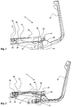
- the Fig. 1 to 3 show the same parts of a chair 11, the operation of which is illustrated by different settings shown in the drawings.
- the (incomplete) chair 11 has a base 13 which can be attached to a chair base (eg in the form of a pillar with optional stand and rollers), a vehicle or other object and may have attachment means for this purpose.
- the chair 11 has a backrest support 55 adapted to support a backrest (not shown) and a seat support 35 adapted to support a seat surface (not shown).
- the backrest support 55 is pivotable, in particular rotatable, connected to the base 13, whereby an angular increase between the seat and backrest and thus a further reclining is possible.
- the rotation of the backrest support 55 takes place about a substantially horizontal axis of rotation 95, which is provided behind and / or below the seat surface.
- the seat support 35 and thus the seat, as shown in the drawings, relative to the base 13 is designed to be movable.
- the movement of the seat support 35 is coupled with advantage to the movement of the backrest support 55.
- the backrest support 55 is rotatably connected to the seat support 35 about a substantially horizontal axis of rotation 97.
- the axis of rotation 97 is arranged at a fixed distance from the axis of rotation 95 and itself rotatable about the axis of rotation 95.
- the axis of rotation 97 is positioned above the axis of rotation 95. Regardless of the specific embodiment, it is advantageous if the connection between the backrest support 55 and seat support 35 (or here the axis of rotation 97) is positioned further back than the connection between the backrest support 55 and the base 13 (or here the axis of rotation 95). Since the backrest support 55 during pivoting back, which represents a rotation in the present example, conveniently moves slightly downward, the seat, if the connection to the backrest support 55 is further back than the axis of rotation 95, pulled down.
- the seat carrier 35 relative to the base 13 in the direction of the backrest support 55 - ie to the rear - Is designed to be movable.
- the connection between seat support 35 and base 13 allows the described movement of the seat support 35.
- it is formed by a slot 91 and a slidably mounted therein slider 93.
- the slider 93 also assumes the function of a stop or the distance by which the backrest support 55 can be pivoted to the rear, limited by the length of the slot 91.
- this movement of the backrest support 55 limiting stop can also be mounted elsewhere in the chair 11.
- the mobility of the seat support 35 is only a preferred feature. Through them and their preferred coupling to the movement of the backrest support 55, the distance between the seat support 35 and backrest support 55 increases when pivoting back the latter less than that in a relative to the base 13 immovable seat support 35 would be the case. Due to the connection between the backrest support 55 and the seat support 35, the seat support 35 is pulled backwards and, depending on the embodiment of the connection, when the backrest support 55 is pivoted backwards. This prevents withdrawal of the shirt from the pants when leaning back. However, the seat support 35 could also be immobile relative to the base 13 and / or be firmly connected thereto.
- the seat support 35 (in particular in the region of its backrest support 55 facing, ie rear side) supported on the base 13 and / or only on the base 13 (ie not directly) with the backrest support 55 is connected.
- the variant shown in the drawings is preferred for the reasons described. It also has a mechanism which causes an automatic movement of the backrest support 55 in its initial position (ie before pivoting back) as soon as the person sitting on the chair no longer exerts pressure on the backrest, so for example bends forward, or an optional Locking the backrest support 55, which prevents its movement into the starting position, is released.
- the mechanism has a bending spring 73. This is in contact with the mechanism at three points spaced apart along the bending spring 73.
- the mechanism is or is a first support element 83, a second support element 85, and a third Support member 89 at the points described above in contact with the bending spring 73 and brings there forces on the bending spring 73, which cause the bending of the bending spring 73.
- One of the support elements 85 is arranged on the backrest support 55 or fixedly connected thereto and its movement is thus coupled to the movement of the backrest support 55.
- the support element 85 is arranged on an extension 57 of the backrest support 55, which extends relative to the axis of rotation 95 upwards. Since the support member 85 is spaced from the axis of rotation 95, rotation of the back support 55 results in rotation of the support member 85 and movement (in response to movement of the seat back support 55) to and from the flexure spring 73. Regardless of the specific embodiment, it is advantageous if one of the support elements 85 is designed to be movable, with its movement being coupled to the movement of the backrest support 55 and the movement path being the location at which the bending spring 73 is in the starting position of the backrest support 55. or the space she occupies. This is in the variant shown in the area between the two other support elements 83, 87.
- each one of these two support elements 83,87 is arranged there in the region of the front and the back of the seat.
- the illustrated embodiment has a fourth support element 89 which can be displaced along the bending spring 73.
- This can be arranged, for example, on an extension 88 which is displaceably mounted in a guide rail 90 mounted on the seat support 35 and running alongside the bending spring 73.
- the extension 88 may, as shown, optionally have an opening into or through which the bending spring 73 extends and which advantageously also forms the fourth support element 89.
- the first 83 and / or second 85 and / or third 87 support member may be fixed to the bending spring 73 or only touch them. Conveniently, one or two of the support elements only touch the bending spring 73, so that the bending spring 73 can slide over these support elements during bending.
- the bending spring 73 in the example shown is plate-shaped and (in the starting position of the backrest support) substantially straight. It extends from the front of the seat to the back.
- the support member 85 disposed on the backrest support 55 is movable transversely to the bending spring 73, wherein the rotation axis 95 is behind the support member 85 so that the pivoting back of the backrest support 55 leads to an upward movement of the support member 85.
- the two support elements 83, 87 are advantageously positioned in the region of two opposite ends 75, 77 of the bending spring 73 and / or in the region of two opposite sides of the seat support 35 or the seat surface (in particular the front and rear). As shown, they can be arranged at a substantially constant distance from the seat carrier 35 and / or from the seat surface and / or from the base 13.
Claims (10)
- Siège (11) comprenant :- une base (13),- une assise qui est reliée à la base (13) par un support d'assise (35),- un dossier, placé en angle avec l'assise, qui est relié à la base (13) par un support de dossier (55) ainsi- qu'un mécanisme pour modifier l'angle entre l'assise et le dossier qui est configuré pour produire, lors de l'agrandissement de l'angle au moyen d'un ressort de flexion (73) substantiellement en forme de plaque ou de barre, une force de rappel qui agit à l'encontre de l'agrandissement, cependant que- le mécanisme s'appuie sur le ressort de flexion (73) avec plusieurs éléments d'appui (83, 85, 87, 89) et est configuré pour appliquer, lors de l'agrandissement de l'angle par les éléments d'appui (83, 85, 87, 89), une contrainte de flexion sur le ressort de flexion (73),- l'un des éléments d'appui (85) est configuré dans ce but en étant mobile par rapport à l'un ou à plusieurs des autres éléments d'appui (83, 85, 87, 89),- l'élément d'appui mobile (85) est placé entre deux des autres éléments d'appui (83, 87) et- le mouvement de l'élément d'appui mobile (85) est couplé au mouvement du support de dossier (55),caractérisé en ce que l'un des éléments d'appui (89) est configuré déplaçable le long du ressort de flexion (73), le support de dossier (55) étant à l'état immobile.
- Siège selon la revendication 1, caractérisé en ce- qu'un premier, un second et un troisième élément d'appui (83, 85, 87) sont prévus,- que le premier, le second et le troisième élément d'appui (81, 83, 85) sont placés en étant placés distribués en étant espacés l'un de l'autre le long du ressort de flexion (73),- que le second élément d'appui (85) est placé entre le premier et le troisième élément d'appui (83, 87) et- que le second élément d'appui (85) est placé sur le support de dossier (55) et est mobile avec celui-ci.
- Siège selon l'une des revendications 1 ou 2, caractérisé en ce que deux éléments d'appui (83, 87) s'appuient sur un côté, de préférence sur le côté supérieur, du ressort de flexion (73) et qu'un élément d'appui (85) s'appuie sur le côté opposé, de préférence sur le côté inférieur, du ressort de flexion (73) et est configuré mobile transversalement par rapport à une liaison entre les deux autres éléments d'appui (83, 87).
- Siège selon l'une des revendications 1 à 3, caractérisé en ce que deux des éléments d'appui (83, 87) sont placés sur le support d'assise (35) et que le ressort de flexion (73) s'étend de l'un à l'autre des deux éléments d'appui (83, 87), cependant que l'un des deux éléments d'appui (83, 87) est placé de préférence dans la zone du côté antérieur du support d'assise (35) et l'autre des deux éléments d'appui (35) est placé de préférence dans la zone du côté postérieur du support d'assise (35).
- Siège selon l'une des revendications 1 à 4, caractérisé en ce que le ressort de flexion (73) s'étend le long du côté inférieur de l'assise du côté antérieur du support d'assise (35) au côté postérieur du support d'assise (35).
- Siège selon l'une des revendications 1 à 5, caractérisé en ce que le support d'assise (35) est relié de manière mobile à la base (13), le support de dossier (55) est relié de manière rotative à la base (13) et le support de dossier (55) est relié de manière rotative au support d'assise (35).
- Siège selon l'une des revendications 1 à 5, caractérisé en ce que l'élément d'appui mobile (85) est placé sur le support de dossier (55) et le support de dossier (55) est relié de manière rotative à la base (13) par un axe de rotation (95), cependant que l'axe de rotation (95) est placé entre l'élément d'appui mobile (85) et le support de dossier (55).
- Siège selon l'une des revendications 1 à 7, caractérisé en ce que le support d'assise (35) est configuré déplaçable par rapport à la base (13), cependant que le déplacement du support d'assise (35) est couplé au mouvement du support de dossier (55), cependant que le support d'assise (35) est relié dans ce but à la base (13), de préférence par un trou oblong (91) et un coulisseau (93) placé mobile dans le trou oblong (91).
- Siège selon l'une des revendications 1 à 8, caractérisé en ce que le support de dossier (55) est relié de manière mobile, en particulier de manière rotative, au support d'assise (35) dans la zone du côté gauche et du côté droit du support d'assise (35) respectivement par un moyen de connexion, en particulier par un logement d'axe, cependant que le ressort de flexion (13) s'étend jusque dans la zone entre les moyens de connexion et de préférence à travers cette zone en direction du support de dossier (55), cependant que de préférence un axe qui forme l'un des éléments d'appui (85) s'étend de l'un à l'autre moyen de connexion.
- Siège selon l'une des revendications 1 à 9, caractérisé en ce que le support de dossier (55) s'étend jusqu'en dessous la surface d'assise et/ou le support d'assise (35) et y est relié à la base (13), cependant que le support de dossier (55) est configuré de préférence substantiellement en forme de L.
Applications Claiming Priority (1)
| Application Number | Priority Date | Filing Date | Title |
|---|---|---|---|
| CH01187/13A CH708248A1 (de) | 2013-06-28 | 2013-06-28 | Sitzmöbel mit Biegefeder. |
Publications (2)
| Publication Number | Publication Date |
|---|---|
| EP2818079A1 EP2818079A1 (fr) | 2014-12-31 |
| EP2818079B1 true EP2818079B1 (fr) | 2016-06-15 |
Family
ID=49779809
Family Applications (1)
| Application Number | Title | Priority Date | Filing Date |
|---|---|---|---|
| EP14174982.0A Active EP2818079B1 (fr) | 2013-06-28 | 2014-06-30 | Meubles destinés à s'asseoir |
Country Status (2)
| Country | Link |
|---|---|
| EP (1) | EP2818079B1 (fr) |
| CH (1) | CH708248A1 (fr) |
Cited By (1)
| Publication number | Priority date | Publication date | Assignee | Title |
|---|---|---|---|---|
| JP7191418B2 (ja) | 2018-11-20 | 2022-12-19 | 宣禹實業股▲分▼有限公司 | 椅子類のための同期機構及び椅子類 |
Families Citing this family (2)
| Publication number | Priority date | Publication date | Assignee | Title |
|---|---|---|---|---|
| WO2019204714A1 (fr) | 2018-04-19 | 2019-10-24 | Cramer Llc | Chaise dotée d'un dossier pliable et procédé associés |
| DE102020101034A1 (de) * | 2020-01-17 | 2021-07-22 | Bock 1 Gmbh & Co. Kg | Träger für ein Sitzmöbel |
Family Cites Families (4)
| Publication number | Priority date | Publication date | Assignee | Title |
|---|---|---|---|---|
| AT411962B (de) | 2003-02-18 | 2004-08-26 | Hansen Eckhard Dipl Ing | Stuhl |
| WO2008000295A1 (fr) * | 2006-06-30 | 2008-01-03 | Eckhard Hansen | Siège |
| AT504897B1 (de) * | 2007-05-07 | 2008-09-15 | Hansen Eckhard Dipl Ing | Sitzmöbel |
| CH700921B1 (de) * | 2007-10-16 | 2010-11-15 | Sitag Ag | Personensitz mit einem Federelement. |
-
2013
- 2013-06-28 CH CH01187/13A patent/CH708248A1/de not_active Application Discontinuation
-
2014
- 2014-06-30 EP EP14174982.0A patent/EP2818079B1/fr active Active
Cited By (1)
| Publication number | Priority date | Publication date | Assignee | Title |
|---|---|---|---|---|
| JP7191418B2 (ja) | 2018-11-20 | 2022-12-19 | 宣禹實業股▲分▼有限公司 | 椅子類のための同期機構及び椅子類 |
Also Published As
| Publication number | Publication date |
|---|---|
| EP2818079A1 (fr) | 2014-12-31 |
| CH708248A1 (de) | 2014-12-31 |
Similar Documents
| Publication | Publication Date | Title |
|---|---|---|
| EP2921080B1 (fr) | Chaise | |
| EP0960586B1 (fr) | Chaise, notamment chaise de bureau | |
| EP3409144B1 (fr) | Chaise, notamment chaise de conférence ou de bureau ainsi que procédé de fabrication d'une chaise | |
| EP2609834B1 (fr) | Elément de siège et système d'armature associé | |
| EP2953508B1 (fr) | Mécanisme pour une chaise de bureau | |
| EP2801293B1 (fr) | Elément de siège et sa garniture | |
| EP1911371A1 (fr) | Meuble d'assise, en particulier chaise de bureau | |
| EP1325693A2 (fr) | Chaise | |
| AT12867U1 (de) | Sitzmöbel | |
| EP3295829A1 (fr) | Chaise, en particulier chaise de bureau ou de conférence, procédé de fabrication d'une chaise | |
| DE202005010097U1 (de) | Synchronmechanik | |
| EP2818079B1 (fr) | Meubles destinés à s'asseoir | |
| EP3741258A1 (fr) | Chaise pourvue de mécanisme d'inclinaison de l'assise | |
| EP0995372B1 (fr) | Chaise de bureau avec un dossier suivant | |
| EP3965617A1 (fr) | Siège comprenant une fonction wallaway à double moteur | |
| DE102009037162A1 (de) | Sitzmöbelstück | |
| DE202011000805U1 (de) | Stuhl mit kipp- und torsionsbeweglicher Sitzfläche | |
| EP2172136B1 (fr) | Siège doté d'un élément d'assise et d'un élément de dossier | |
| EP2896326A1 (fr) | Siège, en particulier chaise | |
| EP3281558B1 (fr) | Meuble rembourré avec fonction pour s'allonger | |
| DE102017110262A1 (de) | Beinauflagebeschlag für ein Sitz-/Liegemöbel und ein entsprechendes Sitz-/Liegemöbel | |
| AT506292B1 (de) | Sitzmöbel | |
| CH702970A2 (de) | Stuhl mit Sitzplatte und Rückenlehne. | |
| AT509542A1 (de) | Gelenkbeschlag für sitzmöbel | |
| DE202007009877U1 (de) | Sitzmöbel |
Legal Events
| Date | Code | Title | Description |
|---|---|---|---|
| PUAI | Public reference made under article 153(3) epc to a published international application that has entered the european phase |
Free format text: ORIGINAL CODE: 0009012 |
|
| 17P | Request for examination filed |
Effective date: 20140630 |
|
| AK | Designated contracting states |
Kind code of ref document: A1 Designated state(s): AL AT BE BG CH CY CZ DE DK EE ES FI FR GB GR HR HU IE IS IT LI LT LU LV MC MK MT NL NO PL PT RO RS SE SI SK SM TR |
|
| AX | Request for extension of the european patent |
Extension state: BA ME |
|
| R17P | Request for examination filed (corrected) |
Effective date: 20150409 |
|
| RBV | Designated contracting states (corrected) |
Designated state(s): AL AT BE BG CH CY CZ DE DK EE ES FI FR GB GR HR HU IE IS IT LI LT LU LV MC MK MT NL NO PL PT RO RS SE SI SK SM TR |
|
| GRAP | Despatch of communication of intention to grant a patent |
Free format text: ORIGINAL CODE: EPIDOSNIGR1 |
|
| INTG | Intention to grant announced |
Effective date: 20160128 |
|
| GRAS | Grant fee paid |
Free format text: ORIGINAL CODE: EPIDOSNIGR3 |
|
| GRAA | (expected) grant |
Free format text: ORIGINAL CODE: 0009210 |
|
| AK | Designated contracting states |
Kind code of ref document: B1 Designated state(s): AL AT BE BG CH CY CZ DE DK EE ES FI FR GB GR HR HU IE IS IT LI LT LU LV MC MK MT NL NO PL PT RO RS SE SI SK SM TR |
|
| REG | Reference to a national code |
Ref country code: CH Ref legal event code: EP Ref country code: GB Ref legal event code: FG4D Free format text: NOT ENGLISH |
|
| REG | Reference to a national code |
Ref country code: FR Ref legal event code: PLFP Year of fee payment: 3 |
|
| REG | Reference to a national code |
Ref country code: IE Ref legal event code: FG4D Free format text: LANGUAGE OF EP DOCUMENT: GERMAN |
|
| REG | Reference to a national code |
Ref country code: AT Ref legal event code: REF Ref document number: 806049 Country of ref document: AT Kind code of ref document: T Effective date: 20160715 |
|
| REG | Reference to a national code |
Ref country code: DE Ref legal event code: R096 Ref document number: 502014000938 Country of ref document: DE |
|
| REG | Reference to a national code |
Ref country code: CH Ref legal event code: NV Representative=s name: RIEDERER HASLER AND PARTNER PATENTANWAELTE AG, LI |
|
| REG | Reference to a national code |
Ref country code: LT Ref legal event code: MG4D |
|
| REG | Reference to a national code |
Ref country code: NL Ref legal event code: MP Effective date: 20160615 |
|
| PG25 | Lapsed in a contracting state [announced via postgrant information from national office to epo] |
Ref country code: LT Free format text: LAPSE BECAUSE OF FAILURE TO SUBMIT A TRANSLATION OF THE DESCRIPTION OR TO PAY THE FEE WITHIN THE PRESCRIBED TIME-LIMIT Effective date: 20160615 Ref country code: FI Free format text: LAPSE BECAUSE OF FAILURE TO SUBMIT A TRANSLATION OF THE DESCRIPTION OR TO PAY THE FEE WITHIN THE PRESCRIBED TIME-LIMIT Effective date: 20160615 Ref country code: NO Free format text: LAPSE BECAUSE OF FAILURE TO SUBMIT A TRANSLATION OF THE DESCRIPTION OR TO PAY THE FEE WITHIN THE PRESCRIBED TIME-LIMIT Effective date: 20160915 |
|
| PG25 | Lapsed in a contracting state [announced via postgrant information from national office to epo] |
Ref country code: RS Free format text: LAPSE BECAUSE OF FAILURE TO SUBMIT A TRANSLATION OF THE DESCRIPTION OR TO PAY THE FEE WITHIN THE PRESCRIBED TIME-LIMIT Effective date: 20160615 Ref country code: NL Free format text: LAPSE BECAUSE OF FAILURE TO SUBMIT A TRANSLATION OF THE DESCRIPTION OR TO PAY THE FEE WITHIN THE PRESCRIBED TIME-LIMIT Effective date: 20160615 Ref country code: SE Free format text: LAPSE BECAUSE OF FAILURE TO SUBMIT A TRANSLATION OF THE DESCRIPTION OR TO PAY THE FEE WITHIN THE PRESCRIBED TIME-LIMIT Effective date: 20160615 Ref country code: LV Free format text: LAPSE BECAUSE OF FAILURE TO SUBMIT A TRANSLATION OF THE DESCRIPTION OR TO PAY THE FEE WITHIN THE PRESCRIBED TIME-LIMIT Effective date: 20160615 Ref country code: HR Free format text: LAPSE BECAUSE OF FAILURE TO SUBMIT A TRANSLATION OF THE DESCRIPTION OR TO PAY THE FEE WITHIN THE PRESCRIBED TIME-LIMIT Effective date: 20160615 Ref country code: GR Free format text: LAPSE BECAUSE OF FAILURE TO SUBMIT A TRANSLATION OF THE DESCRIPTION OR TO PAY THE FEE WITHIN THE PRESCRIBED TIME-LIMIT Effective date: 20160916 |
|
| PG25 | Lapsed in a contracting state [announced via postgrant information from national office to epo] |
Ref country code: BE Free format text: LAPSE BECAUSE OF NON-PAYMENT OF DUE FEES Effective date: 20160630 |
|
| PG25 | Lapsed in a contracting state [announced via postgrant information from national office to epo] |
Ref country code: SK Free format text: LAPSE BECAUSE OF FAILURE TO SUBMIT A TRANSLATION OF THE DESCRIPTION OR TO PAY THE FEE WITHIN THE PRESCRIBED TIME-LIMIT Effective date: 20160615 Ref country code: CZ Free format text: LAPSE BECAUSE OF FAILURE TO SUBMIT A TRANSLATION OF THE DESCRIPTION OR TO PAY THE FEE WITHIN THE PRESCRIBED TIME-LIMIT Effective date: 20160615 Ref country code: IS Free format text: LAPSE BECAUSE OF FAILURE TO SUBMIT A TRANSLATION OF THE DESCRIPTION OR TO PAY THE FEE WITHIN THE PRESCRIBED TIME-LIMIT Effective date: 20161015 Ref country code: EE Free format text: LAPSE BECAUSE OF FAILURE TO SUBMIT A TRANSLATION OF THE DESCRIPTION OR TO PAY THE FEE WITHIN THE PRESCRIBED TIME-LIMIT Effective date: 20160615 Ref country code: RO Free format text: LAPSE BECAUSE OF FAILURE TO SUBMIT A TRANSLATION OF THE DESCRIPTION OR TO PAY THE FEE WITHIN THE PRESCRIBED TIME-LIMIT Effective date: 20160615 |
|
| PG25 | Lapsed in a contracting state [announced via postgrant information from national office to epo] |
Ref country code: SM Free format text: LAPSE BECAUSE OF FAILURE TO SUBMIT A TRANSLATION OF THE DESCRIPTION OR TO PAY THE FEE WITHIN THE PRESCRIBED TIME-LIMIT Effective date: 20160615 Ref country code: ES Free format text: LAPSE BECAUSE OF FAILURE TO SUBMIT A TRANSLATION OF THE DESCRIPTION OR TO PAY THE FEE WITHIN THE PRESCRIBED TIME-LIMIT Effective date: 20160615 Ref country code: PT Free format text: LAPSE BECAUSE OF FAILURE TO SUBMIT A TRANSLATION OF THE DESCRIPTION OR TO PAY THE FEE WITHIN THE PRESCRIBED TIME-LIMIT Effective date: 20161017 Ref country code: PL Free format text: LAPSE BECAUSE OF FAILURE TO SUBMIT A TRANSLATION OF THE DESCRIPTION OR TO PAY THE FEE WITHIN THE PRESCRIBED TIME-LIMIT Effective date: 20160615 |
|
| REG | Reference to a national code |
Ref country code: DE Ref legal event code: R097 Ref document number: 502014000938 Country of ref document: DE |
|
| REG | Reference to a national code |
Ref country code: IE Ref legal event code: MM4A |
|
| PG25 | Lapsed in a contracting state [announced via postgrant information from national office to epo] |
Ref country code: MC Free format text: LAPSE BECAUSE OF FAILURE TO SUBMIT A TRANSLATION OF THE DESCRIPTION OR TO PAY THE FEE WITHIN THE PRESCRIBED TIME-LIMIT Effective date: 20160615 |
|
| PLBE | No opposition filed within time limit |
Free format text: ORIGINAL CODE: 0009261 |
|
| STAA | Information on the status of an ep patent application or granted ep patent |
Free format text: STATUS: NO OPPOSITION FILED WITHIN TIME LIMIT |
|
| 26N | No opposition filed |
Effective date: 20170316 |
|
| PG25 | Lapsed in a contracting state [announced via postgrant information from national office to epo] |
Ref country code: DK Free format text: LAPSE BECAUSE OF FAILURE TO SUBMIT A TRANSLATION OF THE DESCRIPTION OR TO PAY THE FEE WITHIN THE PRESCRIBED TIME-LIMIT Effective date: 20160615 Ref country code: IE Free format text: LAPSE BECAUSE OF NON-PAYMENT OF DUE FEES Effective date: 20160630 |
|
| REG | Reference to a national code |
Ref country code: FR Ref legal event code: PLFP Year of fee payment: 4 |
|
| PG25 | Lapsed in a contracting state [announced via postgrant information from national office to epo] |
Ref country code: SI Free format text: LAPSE BECAUSE OF FAILURE TO SUBMIT A TRANSLATION OF THE DESCRIPTION OR TO PAY THE FEE WITHIN THE PRESCRIBED TIME-LIMIT Effective date: 20160615 |
|
| PG25 | Lapsed in a contracting state [announced via postgrant information from national office to epo] |
Ref country code: HU Free format text: LAPSE BECAUSE OF FAILURE TO SUBMIT A TRANSLATION OF THE DESCRIPTION OR TO PAY THE FEE WITHIN THE PRESCRIBED TIME-LIMIT; INVALID AB INITIO Effective date: 20140630 |
|
| REG | Reference to a national code |
Ref country code: FR Ref legal event code: PLFP Year of fee payment: 5 |
|
| PG25 | Lapsed in a contracting state [announced via postgrant information from national office to epo] |
Ref country code: LU Free format text: LAPSE BECAUSE OF NON-PAYMENT OF DUE FEES Effective date: 20160630 Ref country code: MT Free format text: LAPSE BECAUSE OF FAILURE TO SUBMIT A TRANSLATION OF THE DESCRIPTION OR TO PAY THE FEE WITHIN THE PRESCRIBED TIME-LIMIT Effective date: 20160615 Ref country code: CY Free format text: LAPSE BECAUSE OF FAILURE TO SUBMIT A TRANSLATION OF THE DESCRIPTION OR TO PAY THE FEE WITHIN THE PRESCRIBED TIME-LIMIT Effective date: 20160615 Ref country code: MK Free format text: LAPSE BECAUSE OF FAILURE TO SUBMIT A TRANSLATION OF THE DESCRIPTION OR TO PAY THE FEE WITHIN THE PRESCRIBED TIME-LIMIT Effective date: 20160615 |
|
| PG25 | Lapsed in a contracting state [announced via postgrant information from national office to epo] |
Ref country code: BG Free format text: LAPSE BECAUSE OF FAILURE TO SUBMIT A TRANSLATION OF THE DESCRIPTION OR TO PAY THE FEE WITHIN THE PRESCRIBED TIME-LIMIT Effective date: 20160615 |
|
| PGFP | Annual fee paid to national office [announced via postgrant information from national office to epo] |
Ref country code: DE Payment date: 20180625 Year of fee payment: 5 |
|
| PGFP | Annual fee paid to national office [announced via postgrant information from national office to epo] |
Ref country code: FR Payment date: 20180620 Year of fee payment: 5 |
|
| PG25 | Lapsed in a contracting state [announced via postgrant information from national office to epo] |
Ref country code: AL Free format text: LAPSE BECAUSE OF FAILURE TO SUBMIT A TRANSLATION OF THE DESCRIPTION OR TO PAY THE FEE WITHIN THE PRESCRIBED TIME-LIMIT Effective date: 20160615 Ref country code: TR Free format text: LAPSE BECAUSE OF FAILURE TO SUBMIT A TRANSLATION OF THE DESCRIPTION OR TO PAY THE FEE WITHIN THE PRESCRIBED TIME-LIMIT Effective date: 20160615 |
|
| PGFP | Annual fee paid to national office [announced via postgrant information from national office to epo] |
Ref country code: IT Payment date: 20180627 Year of fee payment: 5 |
|
| GBPC | Gb: european patent ceased through non-payment of renewal fee |
Effective date: 20180630 |
|
| PG25 | Lapsed in a contracting state [announced via postgrant information from national office to epo] |
Ref country code: GB Free format text: LAPSE BECAUSE OF NON-PAYMENT OF DUE FEES Effective date: 20180630 |
|
| REG | Reference to a national code |
Ref country code: DE Ref legal event code: R119 Ref document number: 502014000938 Country of ref document: DE |
|
| PG25 | Lapsed in a contracting state [announced via postgrant information from national office to epo] |
Ref country code: IT Free format text: LAPSE BECAUSE OF NON-PAYMENT OF DUE FEES Effective date: 20190630 Ref country code: DE Free format text: LAPSE BECAUSE OF NON-PAYMENT OF DUE FEES Effective date: 20200101 |
|
| PG25 | Lapsed in a contracting state [announced via postgrant information from national office to epo] |
Ref country code: FR Free format text: LAPSE BECAUSE OF NON-PAYMENT OF DUE FEES Effective date: 20190630 |
|
| REG | Reference to a national code |
Ref country code: AT Ref legal event code: MM01 Ref document number: 806049 Country of ref document: AT Kind code of ref document: T Effective date: 20190630 |
|
| PG25 | Lapsed in a contracting state [announced via postgrant information from national office to epo] |
Ref country code: AT Free format text: LAPSE BECAUSE OF NON-PAYMENT OF DUE FEES Effective date: 20190630 |
|
| PGFP | Annual fee paid to national office [announced via postgrant information from national office to epo] |
Ref country code: CH Payment date: 20230702 Year of fee payment: 10 |
|
| REG | Reference to a national code |
Ref country code: CH Ref legal event code: PK Free format text: BERICHTIGUNGEN |