EP2816706B1 - Power supply device, power receiving device, charging system, and obstacle detection method - Google Patents
Power supply device, power receiving device, charging system, and obstacle detection method Download PDFInfo
- Publication number
- EP2816706B1 EP2816706B1 EP13749243.5A EP13749243A EP2816706B1 EP 2816706 B1 EP2816706 B1 EP 2816706B1 EP 13749243 A EP13749243 A EP 13749243A EP 2816706 B1 EP2816706 B1 EP 2816706B1
- Authority
- EP
- European Patent Office
- Prior art keywords
- electric
- test data
- data string
- modulated signal
- power level
- Prior art date
- Legal status (The legal status is an assumption and is not a legal conclusion. Google has not performed a legal analysis and makes no representation as to the accuracy of the status listed.)
- Active
Links
- 238000001514 detection method Methods 0.000 title claims description 25
- 230000005540 biological transmission Effects 0.000 claims description 173
- 238000000034 method Methods 0.000 claims description 23
- 238000004891 communication Methods 0.000 claims description 13
- 230000005674 electromagnetic induction Effects 0.000 claims description 10
- 230000035945 sensitivity Effects 0.000 description 10
- 238000010586 diagram Methods 0.000 description 6
- 230000003252 repetitive effect Effects 0.000 description 6
- 238000012986 modification Methods 0.000 description 2
- 230000004048 modification Effects 0.000 description 2
- 230000007423 decrease Effects 0.000 description 1
- 230000003247 decreasing effect Effects 0.000 description 1
- 230000000694 effects Effects 0.000 description 1
Images


Classifications
-
- H—ELECTRICITY
- H04—ELECTRIC COMMUNICATION TECHNIQUE
- H04B—TRANSMISSION
- H04B5/00—Near-field transmission systems, e.g. inductive or capacitive transmission systems
- H04B5/70—Near-field transmission systems, e.g. inductive or capacitive transmission systems specially adapted for specific purposes
- H04B5/79—Near-field transmission systems, e.g. inductive or capacitive transmission systems specially adapted for specific purposes for data transfer in combination with power transfer
-
- H—ELECTRICITY
- H01—ELECTRIC ELEMENTS
- H01F—MAGNETS; INDUCTANCES; TRANSFORMERS; SELECTION OF MATERIALS FOR THEIR MAGNETIC PROPERTIES
- H01F38/00—Adaptations of transformers or inductances for specific applications or functions
- H01F38/14—Inductive couplings
-
- H—ELECTRICITY
- H02—GENERATION; CONVERSION OR DISTRIBUTION OF ELECTRIC POWER
- H02J—CIRCUIT ARRANGEMENTS OR SYSTEMS FOR SUPPLYING OR DISTRIBUTING ELECTRIC POWER; SYSTEMS FOR STORING ELECTRIC ENERGY
- H02J50/00—Circuit arrangements or systems for wireless supply or distribution of electric power
- H02J50/10—Circuit arrangements or systems for wireless supply or distribution of electric power using inductive coupling
-
- H—ELECTRICITY
- H02—GENERATION; CONVERSION OR DISTRIBUTION OF ELECTRIC POWER
- H02J—CIRCUIT ARRANGEMENTS OR SYSTEMS FOR SUPPLYING OR DISTRIBUTING ELECTRIC POWER; SYSTEMS FOR STORING ELECTRIC ENERGY
- H02J50/00—Circuit arrangements or systems for wireless supply or distribution of electric power
- H02J50/60—Circuit arrangements or systems for wireless supply or distribution of electric power responsive to the presence of foreign objects, e.g. detection of living beings
-
- H—ELECTRICITY
- H02—GENERATION; CONVERSION OR DISTRIBUTION OF ELECTRIC POWER
- H02J—CIRCUIT ARRANGEMENTS OR SYSTEMS FOR SUPPLYING OR DISTRIBUTING ELECTRIC POWER; SYSTEMS FOR STORING ELECTRIC ENERGY
- H02J50/00—Circuit arrangements or systems for wireless supply or distribution of electric power
- H02J50/80—Circuit arrangements or systems for wireless supply or distribution of electric power involving the exchange of data, concerning supply or distribution of electric power, between transmitting devices and receiving devices
-
- H—ELECTRICITY
- H03—ELECTRONIC CIRCUITRY
- H03C—MODULATION
- H03C1/00—Amplitude modulation
-
- H—ELECTRICITY
- H03—ELECTRONIC CIRCUITRY
- H03C—MODULATION
- H03C3/00—Angle modulation
-
- H—ELECTRICITY
- H03—ELECTRONIC CIRCUITRY
- H03D—DEMODULATION OR TRANSFERENCE OF MODULATION FROM ONE CARRIER TO ANOTHER
- H03D1/00—Demodulation of amplitude-modulated oscillations
-
- H—ELECTRICITY
- H03—ELECTRONIC CIRCUITRY
- H03D—DEMODULATION OR TRANSFERENCE OF MODULATION FROM ONE CARRIER TO ANOTHER
- H03D3/00—Demodulation of angle-, frequency- or phase- modulated oscillations
-
- H—ELECTRICITY
- H02—GENERATION; CONVERSION OR DISTRIBUTION OF ELECTRIC POWER
- H02J—CIRCUIT ARRANGEMENTS OR SYSTEMS FOR SUPPLYING OR DISTRIBUTING ELECTRIC POWER; SYSTEMS FOR STORING ELECTRIC ENERGY
- H02J2310/00—The network for supplying or distributing electric power characterised by its spatial reach or by the load
- H02J2310/40—The network being an on-board power network, i.e. within a vehicle
- H02J2310/48—The network being an on-board power network, i.e. within a vehicle for electric vehicles [EV] or hybrid vehicles [HEV]
Definitions
- the present invention relates to an electric supply apparatus according to the preamble of claim 1 that supplies electric power in a contactless manner using electromagnetic induction, a charging system according to claim 5, including the electric supply apparatus and the electric reception apparatus, and also to an obstacle detection method according to claim 7.
- This energy supply technique supplies electric power to magnetrons from a microwave power source in an electric supply apparatus placed on the ground such as a parking lot and causes the magnetrons to generate microwaves.
- the microwaves generated from the respective magnetrons are sent through respective electric transmission antennas to an electric reception apparatus disposed at the bottom surface of the vehicle.
- the microwaves received by the electric reception apparatus are converted into electric power, rectified to be converted into DC electric power, and then supplied to the storage battery.
- Such an energy supply technique has a problem in that, when there is an obstacle between an electric supply side and an electric reception side for microwaves, this obstacle decreases the transmission efficiency of microwaves.
- the obstacle is a living thing, such as a human or an animal, the living thing is affected by the microwaves.
- Patent Literature 1 discloses a technique for temporarily stopping electric transmission when the transmission efficiency of electric power supplied in a contactless manner from the electric transmission unit to the electric reception unit is less than a specified value. This is because there may be an obstacle between the electric transmission unit and the electric reception unit in this case.
- WO 2008/050917 A1 discloses an electric supply apparatus according to the preamble of claim 1.
- the technique disclosed in PTL 1 has a problem in that the obstacle detection sensitivity is not sufficient in the case of a small obstacle because of a low variation in the transmission efficiency in this case.
- An electric supply apparatus is defined in claim 1.
- a charging system includes the features of claim 5 and is a charging system including: an electric reception apparatus that is provided in a vehicle; and an electric supply apparatus that supplies electric power in a contactless manner to the electric reception apparatus using electromagnetic induction, in which the electric supply apparatus includes: a first transmitting section that transmits a first test data string including a predetermined data sequence to the electric reception apparatus using the electromagnetic induction in a coil; an electric power control section that controls the first transmitting section to repeatedly transmit the first test data string from the transmitting section while increasing a transmission electric power level; a first receiving section that receives a data string transmitted from the electric reception apparatus as a second test data string obtained by the electric reception apparatus via demodulation of the first test data string received by the electric reception apparatus; and a determination section that determines whether the first test data string transmitted by the first transmitting section coincides with the second test data string received by the first receiving section, and determines whether there is an obstacle between the electric reception apparatus and the electric supply apparatus based on a transmission electric power level used for transmission of the first
- An obstacle detection method for determining whether there is an obstacle between an electric reception apparatus that is provided in a vehicle and an electric supply apparatus that supplies electric power in a contactless manner to the electric reception apparatus using electromagnetic induction, the method including: transmitting a first test data string including a predetermined data sequence to the electric reception apparatus using the electromagnetic induction in a coil; controlling transmission of the first test data string to be performed in the transmitting of the first test data string; and determining whether there is an obstacle between the electric reception apparatus and the electric supply apparatus based on whether the first test data string transmitted in the transmitting of the first test data string coincides with a second test data string obtained by the electric reception apparatus via demodulation of the first test data string received by the electric reception apparatus.
- the present invention makes it possible to obtain a sufficient obstacle detection sensitivity even in the case of a small obstacle.
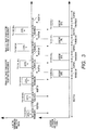
- FIG. 1 is a block diagram illustrating the configuration of charging system 100 according to Embodiment 1 of the present invention.
- Charging system 100 includes electric transmission unit 120 and electric reception unit 150.
- Electric transmission unit 120 includes power source circuit 121, electric transmission inverter 122, electric transmission side microcomputer 123, electric transmission side receiving circuit 124, and electric transmission coil 125.
- Power source circuit 121 is a power source that generates a direct current from a home power source, and for example, generates a DC power source from AC electric energy of approximately 100 to 240 V to output the DC power source to electric transmission inverter 122.
- Electric transmission inverter 122 generates higher frequency AC electric energy from DC electric energy outputted from power source circuit 121 according to the control of electric transmission side microcomputer 123, and supplies the higher frequency AC electric energy to electric transmission coil 125.
- Electric transmission side microcomputer 123 previously stores a predetermined test data string (for example, an 8-bit string), and controls electric transmission inverter 122 to transmit the test data string with low electric power before the start of electric supply to electric reception unit 150. An assumption is made that the test data string is transmitted through amplitude modulation or phase modulation. Electric transmission side microcomputer 123 increases the transmission electric power level (hereinafter, simply referred to as "electric power level") of a test data string at every transmission of a test data string until receiving the correct test data string from electric transmission side receiving circuit 124. When receiving the correct test data string from electric transmission side receiving circuit 124, electric transmission side microcomputer 123 then determines whether there is an obstacle on the basis of the electric power level at that time.
- a predetermined test data string for example, an 8-bit string
- Electric transmission side microcomputer 123 increases the transmission electric power level (hereinafter, simply referred to as "electric power level") of a test data string at every transmission of a test data string until receiving the correct test data string from electric transmission side
- Electric transmission side receiving circuit 124 receives the test data string transmitted from electric reception unit 150, and outputs the received test data string to electric transmission side microcomputer 123.
- Electric transmission coil 125 generates electromagnetic induction from electric energy supplied from electric transmission inverter 122, and supplies electric power to electric reception coil 151 of electric reception unit 150.
- Electric reception unit 150 includes electric reception coil 151, electric reception side receiving circuit/inverter 152, electric reception side microcomputer 153, power source circuit 154, switch 155, rectifier 156, filter circuit 157, and load 158.
- Electric reception coil 151 supplies electric power supplied from electric transmission coil 125 of electric transmission unit 120 to electric reception side receiving circuit/inverter 152 and rectifier 156.
- Electric reception side receiving circuit/inverter 152 demodulates the test data string included in the electric power supplied from electric reception coil 151, and outputs the demodulated test data string to electric reception side microcomputer 153.
- Electric reception side microcomputer 153 amplitude-modulates the test data string outputted from electric reception side receiving circuit/inverter 152 using power source circuit 154, and controls electric reception side receiving circuit/inverter 152 to transmit the amplitude-modulated test data string to electric transmission unit 120 with an electric power level that can be received by electric transmission unit 120.
- electric transmission unit 120 and electric reception unit 150 transmit and receive the test data string mutually using the electromagnetic induction in the coil, and electric reception unit 150 amplitude-modulates the demodulation result of the test data string transmitted from electric transmission unit 120 without modification, and sends back the amplitude-modulated demodulation result to electric transmission unit 120. That is, even if the demodulated test data string has an error, the test data string having the error is sent back without modification.
- Power source circuit 154 is, for example, a storage battery and is charged after the start of electric transmission.
- Switch 155 is controlled by a not-illustrated control section to be turned off during transmission and reception of the test data string before the start of electric reception from electric transmission unit 120, and to be turned on after the starts of electric reception from electric transmission unit 120. Accordingly, switch 155 can isolate load 158 to avoid the influence on transmission and reception of the test data string.
- Rectifier 156 rectifies a current supplied from electric reception coil 151, and filter circuit 157 filter-processes the current rectified by rectifier 156, and outputs the filter-processed current to load 158.
- Load 158 is a battery to be charged by this charging system and is charged with the current outputted from filter circuit 157.
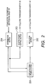
- FIG. 2 is a block diagram illustrating the functional configuration of electric transmission side microcomputer 123 illustrated in FIG. 1 .
- test data string storing section 201 stores a test data string (for example, an 8-bit string) having a predetermined data sequence, and outputs the test data string to modulation section 202 and determination section 204 according to instructions from determination section 204.
- a test data string for example, an 8-bit string
- Modulation section 202 amplitude-modulates or phase-modulates the test data string outputted from test data string storing section 201, and outputs the modulated test data string to the electric-transmission inverter 122.
- electric power control section 203 According to instructions from determination section 204, electric power control section 203 generates an electric power control signal for increasing the electric power level of the test data string at every transmission of the test data string, and outputs the generated electric power control signal to electric transmission inverter 122.
- Determination section 204 determines whether the test data string outputted from test data string storing section 201 coincides with the test data string from the electric reception side inverter, which is outputted from electric transmission side receiving circuit 124. Determination section 204 stores in advance the electric power level obtained when transmission and reception of a test data string in the case of no obstacle was successful. If the electric power level in the above determination resulting in coincidence is equal to the stored electric power level, determination section 204 determines that there is no obstacle. If the electric power level in the above determination resulting in coincidence exceeds the stored electric power level, determination section 204 determines that there is an obstacle.
- FIG. 3 illustrates how a test data string is transmitted and received between electric transmission unit 120 and electric reception unit 150.
- electric transmission unit 120 transmits a test data string "01100100" at electric power level 1, which is the minimum electric power.
- electric reception unit 150 cannot receive the test data string at electric power level 1 and cannot send back the test data string.
- electric transmission unit 120 increases the level to electric power level 2 and transmits the test data string "01100100."
- Electric reception unit 150 cannot receive the test data string even at electric power level 2 and cannot send back the test data string.
- electric transmission unit 120 Since the test data string transmitted at electric power level 2 cannot be received at a predetermined receiving timing, electric transmission unit 120 increases the level to electric power level 3 and transmits the test data string "01100100.” Electric reception unit 150 has received the test data string, but the test data string has a receiving error due to the low electric power level. Thus, electric reception unit 150 sets the test data string to "01000010,” and sends back the test data string to electric transmission unit 120 at the electric power level receivable by electric transmission unit 120.
- Electric transmission unit 120 recognizes that the test data string transmitted at electric power level 3 has been received with an error by electric reception unit 150, thus increases the level to electric power level 4 and transmits the test data string "01100100.”
- Electric reception unit 150 has received the test data string, but the test data string still has a receiving error due to the low electric power level. Thus, electric reception unit 150 sets the test data string to "01000100,” and sends back the test data string to electric transmission unit 120.
- Electric transmission unit 120 recognizes that the test data string transmitted at electric power level 4 is received with an error by electric reception unit 150, thus increases the level to electric power level 5 and transmits the test data string "01100100.”
- Electric reception unit 150 correctly receives the test data string and therefore sends back the test data string "01100100” to electric transmission unit 120.
- electric transmission unit 120 and electric reception unit 150 have previously succeeded in transmission and reception of the test data string at electric power level 5 in the case of no - obstacle between electric transmission unit 120 and electric reception unit 150, electric transmission unit 120 determines that there is no obstacle between electric transmission unit 120 and electric reception unit 150. This success in transmission and reception means that the test data string transmitted by electric transmission unit 120 coincides with the test data string received from electric reception unit 150 by electric transmission unit 120.
- electric transmission unit 120 transmits the test data string "01100100” at electric power level 6
- electric reception unit 150 correctly receives the test data string and sends back the test data string "01100100” to electric transmission unit 120.
- electric transmission unit 120 increases in a stepwise manner the electric power level in each repetitive transmission of a test data string until receiving a test data string coinciding with a transmitted test data string, from electric reception unit 150; if the electric power level of transmission used when electric transmission unit 120 has correctly received a test data string is equal to an electric power level used in previous successful transmission and reception of a test data string in the case of no obstacle, it is determined that there is no obstacle; and if the electric power level of transmission when electric transmission unit 120 has correctly received a test data string exceeds an electric power level used in previous successful transmission and reception of a test data string in the case of no obstacle, it is determined that there is an obstacle. Accordingly, it is possible to detect a small obstacle and thus to improve the obstacle detection sensitivity.
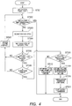
- FIG. 4 is a flowchart illustrating an obstacle detection procedure of electric transmission unit 120 according to Embodiment 1 of the present invention.
- Step (hereinafter abbreviated to "ST") 301 sets electric power level 1, and ST 302 determines whether test data strings are transmitted a number of times greater than a predetermined number of times, completes the obstacle detection procedure if the number of times of the transmission is equal to or more than the predetermined number of times, and progresses to ST 303 if the number of times of transmission is less than the predetermined number of times.
- ST 303 transmits a test data string at the set electric power level, and ST 304 waits for reception of a test data string sent back from electric reception unit 150.
- ST 305 determines whether the test data string sent back from electric reception unit 150 is received, progresses to ST 306 if it is received, and increases the electric power level in ST 307 and sends back to ST 302 if it is not received.
- ST 306 determines whether the test data string sent back from electric reception unit 150 is correct, progresses to ST 308 if it is correct, and increases the electric power level in ST 307 to send back to ST 302 if it is not correct.
- ST 308 determines whether an electric power level of transmission for correctly receiving a test data string is equal to an electric power level used in successful transmission and reception of a test data string in the case of no obstacle, progresses to ST 309 if this condition is satisfied, and progresses to ST 312 if this condition is not satisfied.
- ST 309 determines that electric transmission is possible because of no obstacle, and ST 310 transmits an electric transmission start signal to electric reception unit 150, ST 311 starts electric transmission and completes the obstacle detection procedure.
- ST 312 determines that electric transmission is impossible because of the presence of an obstacle, and completes the obstacle detection procedure.
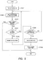
- FIG. 5 is a flowchart illustrating an electric reception preparation procedure of electric reception unit 150 according to Embodiment 1 of the present invention.
- ST 401 turns off switch 155, and ST 402 waits for reception of a test data string transmitted from electric transmission unit 120.
- ST 403 determines whether a predetermined time period elapses after waiting for reception of a test data string, completes the electric reception preparation procedure if the predetermined time period elapses, and progresses to ST 404 if the predetermined time period does not elapse.
- ST 404 determines whether a test data string is received, progresses to ST 405 if it is received, and sends back to ST 402 if it is not received.
- ST 405 transmits the received test data string to electric transmission unit 120, ST 406 determines whether an electric transmission start signal is received, progresses to ST 407 if it is received, and sends back to ST 402 if it is not received.
- ST 407 turns on switch 155, and ST 408 starts electric reception of electric power supplied from electric transmission unit 120.
- the electric transmission unit increases in a stepwise manner the electric power level in each repetitive transmission of a test data string until receiving a test data string coinciding with a transmitted test data string, from the electric reception unit; and whether there is an obstacle is detected on the basis of an electric power level used for transmission in which the electric transmission unit has correctly received a test data string.
- test data string is transmitted through inter-coil communication from the electric reception unit.
- the test data string may be transmitted from the electric reception unit to the electric transmission unit through another communication method, such as radio communication or infrared communication.
- a charging system according to Embodiment 2 of the present invention has the same configuration as that illustrated in FIG. 1 of Embodiment 1 except that the functions of the electric transmission side microcomputer and the electric reception side microcomputer are different. Therefore, the different functions will be explained with reference to FIG. 1 and FIG. 2 .
- test data string storing section 201 stores a test data string previously associated with each of electric power levels variable in a stepwise manner. For example, three bits 000 to 111 of a fifth bit to a seventh bit in an 8-bit test data string are previously associated with electric power levels 1 to 8.
- Test data string storing section 201 outputs a test data string to modulation section 202 and determination section 204 according to the instructions from determination section 204. Accordingly, a test data string corresponding to the control of an electric power level by electric power control section 203 can be transmitted.
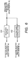
- FIG. 6 is a block diagram illustrating the functional configuration of the electric reception side microcomputer according to Embodiment 2 of the present invention.
- modulation section 501 amplitude-modulates or phase-modulates a demodulated test data string outputted from electric reception side receiving circuit/inverter 152, and outputs the modulated test data string to electric reception side receiving circuit/inverter 152.
- Electric power control section 502 generates an electric power control signal indicating an electric power level represented by the demodulated test data string outputted from electric reception side receiving circuit/inverter 152, and outputs the generated electric power control signal to electric reception side receiving circuit/inverter 152.
- FIG. 7 illustrates how a test data string is transmitted and received between electric transmission unit 120 and electric reception unit 150.
- electric transmission unit 120 transmits a test data string "10100001" representing electric power level 1 at electric power level 1, which is the minimum electric power.
- electric reception unit 150 cannot receive the test data string at electric power level 1 and cannot send back the test data string.
- electric transmission unit 120 increases the level to electric power level 2 and transmits the test data string "10100011" representing electric power level 2.
- Electric reception unit 150 cannot receive the test data string even at electric power level 2 and cannot send back the test data string.
- electric transmission unit 120 increases the level to electric power level 3 and transmits the test data string "10100101" representing electric power level 3.
- Electric reception unit 150 has received the test data string, but the test data string has a receiving error due to the low electric power level. Thus, electric reception unit 150 sends back the test data string "10100001" representing electric power level 1 to electric transmission unit 120.
- electric transmission unit 120 increases the level to electric power level 4 and transmits the test data string "10100111" representing electric power level 4.
- Electric reception unit 150 has received the test data string, but the test data string still has a receiving error due to the low electric power level. Thus, electric. reception unit 150 sends back the test data string "10100101" representing electric power level 3, at electric power level 3 to electric transmission unit 120.
- Electric transmission unit 120 recognizes that the test data string transmitted at electric power level 4 is received with an error by electric reception unit 150, thus increases the level to electric power level 5 and transmits the test data string "10101001" representing electric power level 5.
- Electric reception unit 150 correctly receives the test data string and therefore sends back the test data string "10101001” representing electric power level 5, at electric power level 5 to electric transmission unit 120.
- electric transmission unit 120 and electric reception unit 150 have previously succeeded in transmission and reception of the test data string at electric power level 5 in the case of no obstacle between electric transmission unit 120 and electric reception unit 150, electric transmission unit 120 determines that there is no obstacle between electric transmission unit 120 and electric reception unit 150.
- electric transmission unit 120 transmits the test data string "10101011” representing electric power level 6, at electric power level 6; electric reception unit 150 correctly receives the test data string and sends back the test data string "10101011” representing electric power level 6, at electric power level 6 to electric transmission unit 120.
- electric transmission unit 120 increases in a stepwise manner the electric power level in each repetitive transmission of a test data string in each of electric transmission unit 120 and electric reception unit 150 until receiving a test data string coinciding with a transmitted test data string, from electric reception unit 150; if the electric power level of transmission used when electric transmission unit 120 has correctly received a test data string is equal to an electric power level used in previous successful transmission and reception of a test data string in the case of no obstacle, it is determined that there is no obstacle; and if the electric power level of transmission when electric transmission unit 120 has correctly received a test data string exceeds an electric power level used in previous successful transmission and reception of a test data string in the case of no obstacle, it is determined that there is an obstacle. Accordingly, it is possible to detect a small obstacle and thus to improve the obstacle detection sensitivity.
- the electric power level from the reception side is fixed, the electric power level from the reception side is also increased in a stepwise manner, so that certain transmission and reception sensitivities are required bi-directionally, which results in a more strict condition for successful communication.
- the obstacle detection sensitivity can be further improved.
- FIG. 8 is a flowchart illustrating an obstacle detection procedure of the electric transmission unit according to Embodiment 2 of the present invention.
- the same steps in FIG. 8 as those in FIG. 4 are assigned the same reference numerals as those in FIG. 4 , and repetitive explanations thereof will be omitted.
- ST 601 transmits a test data string representing a set electric power level, at the electric power level.
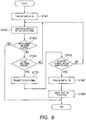
- FIG. 9 is a flowchart illustrating an electric reception preparation procedure of the electric reception unit according to Embodiment 2 of the present invention.
- the same steps in FIG. 9 as those in FIG. 5 are assigned the same reference numerals as those in FIG. 5 , and repetitive explanations thereof will be omitted.
- ST 701 transmits a received test data string to the electric transmission unit at an electric power level represented by the received test data string.
- the electric transmission unit increases in a stepwise manner the electric power level in each repetitive transmission of a test data string in each of electric transmission unit and electric reception unit until receiving a test data string coinciding with a transmitted test data string, from the electric reception unit; and whether there is an obstacle is detected on the basis of an electric power level used for transmission in which the electric transmission unit has correctly received a test data string.
- a sufficient obstacle detection sensitivity can be obtained even in the case of a small obstacle.
- each embodiment involves the test data string having 8 bits.
- the number of bits may be 8 or greater depending on the number of electric power levels variable in a stepwise manner.
- a parity bit may be used in the test data string to detect an error.
- the minimum necessary sufficient electric power level for successful transmission and reception of a test data string may be sought by once decreasing a transmission electric power level to check whether to succeed in transmission and reception of a test data string again and by checking whether to succeed in transmission and reception of the test data string a plurality of times at the minimum transmission electric power level.
- the electric supply apparatus, electric reception apparatus, charging system, and obstacle detection method according to the present invention are suitable for obtaining a sufficient obstacle detection sensitivity.
Landscapes
- Engineering & Computer Science (AREA)
- Power Engineering (AREA)
- Computer Networks & Wireless Communication (AREA)
- Signal Processing (AREA)
- Electric Propulsion And Braking For Vehicles (AREA)
- Charge And Discharge Circuits For Batteries Or The Like (AREA)
- Current-Collector Devices For Electrically Propelled Vehicles (AREA)
Applications Claiming Priority (2)
| Application Number | Priority Date | Filing Date | Title |
|---|---|---|---|
| JP2012028543A JP5147999B1 (ja) | 2012-02-13 | 2012-02-13 | 給電装置、受電装置、充電システム及び障害物検出方法 |
| PCT/JP2013/000689 WO2013121757A1 (ja) | 2012-02-13 | 2013-02-08 | 給電装置、受電装置、充電システム及び障害物検出方法 |
Publications (3)
| Publication Number | Publication Date |
|---|---|
| EP2816706A1 EP2816706A1 (en) | 2014-12-24 |
| EP2816706A4 EP2816706A4 (en) | 2015-09-09 |
| EP2816706B1 true EP2816706B1 (en) | 2018-12-12 |
Family
ID=47890545
Family Applications (1)
| Application Number | Title | Priority Date | Filing Date |
|---|---|---|---|
| EP13749243.5A Active EP2816706B1 (en) | 2012-02-13 | 2013-02-08 | Power supply device, power receiving device, charging system, and obstacle detection method |
Country Status (5)
| Country | Link |
|---|---|
| US (1) | US9484988B2 (enExample) |
| EP (1) | EP2816706B1 (enExample) |
| JP (2) | JP5147999B1 (enExample) |
| CN (1) | CN104094499B (enExample) |
| WO (1) | WO2013121757A1 (enExample) |
Families Citing this family (13)
| Publication number | Priority date | Publication date | Assignee | Title |
|---|---|---|---|---|
| KR102039375B1 (ko) * | 2013-03-08 | 2019-11-04 | 삼성전자주식회사 | 무선 전력 송신기 및 그 제어 방법 |
| US10454303B2 (en) | 2013-11-20 | 2019-10-22 | Wits Co., Ltd. | Non-contact power supply device and non-contact power supply method |
| CN103763720B (zh) * | 2014-01-03 | 2017-02-22 | 北京智谷睿拓技术服务有限公司 | 无线能量传输的障碍事由检测方法和系统 |
| US9931954B2 (en) * | 2014-02-04 | 2018-04-03 | Ford Global Technologies, Llc | Vertical wireless power transfer system for charging electric vehicles |
| JP6555010B2 (ja) * | 2015-08-25 | 2019-08-07 | 船井電機株式会社 | 給電装置 |
| US10336194B2 (en) | 2015-11-13 | 2019-07-02 | Nio Usa, Inc. | Electric vehicle charging device alignment and method of use |
| US10093195B2 (en) | 2015-11-13 | 2018-10-09 | Nio Usa, Inc. | Integrated vehicle charging panel system and method of use |
| US10189363B2 (en) | 2015-11-13 | 2019-01-29 | Nio Usa, Inc. | Electric vehicle roadway charging system and method of use |
| US10059213B2 (en) | 2015-11-13 | 2018-08-28 | Nio Usa, Inc. | Charging devices within wheel portions |
| US9944192B2 (en) | 2015-11-13 | 2018-04-17 | Nio Usa, Inc. | Electric vehicle charging station system and method of use |
| DE102017130169A1 (de) * | 2017-02-24 | 2018-08-30 | Denso Ten Limited | Ladeunterstützungsvorrichtung |
| JP6796024B2 (ja) * | 2017-05-19 | 2020-12-02 | ミネベアミツミ株式会社 | ワイヤレス電力伝送システム、およびワイヤレス電力伝送システムの通信方法 |
| JP6868077B1 (ja) | 2019-11-05 | 2021-05-12 | 日本たばこ産業株式会社 | エアロゾル吸引器用の電源ユニット、エアロゾル吸引器、及びエアロゾル吸引器用の充電ユニット |
Family Cites Families (18)
| Publication number | Priority date | Publication date | Assignee | Title |
|---|---|---|---|---|
| JP4244748B2 (ja) * | 2003-08-27 | 2009-03-25 | カシオ計算機株式会社 | 無線通信装置及びプログラム |
| US8307922B2 (en) | 2005-05-24 | 2012-11-13 | Rearden, Llc | System and method for powering an aircraft using radio frequency signals and feedback |
| KR100836634B1 (ko) | 2006-10-24 | 2008-06-10 | 주식회사 한림포스텍 | 무선 데이타 통신과 전력 전송이 가능한 무접점 충전장치,충전용 배터리팩 및 무접점 충전장치를 이용한 휴대용단말기 |
| KR100819753B1 (ko) * | 2007-07-13 | 2008-04-08 | 주식회사 한림포스텍 | 배터리팩 솔루션을 위한 무접점충전시스템 및 그 제어방법 |
| JP4600462B2 (ja) | 2007-11-16 | 2010-12-15 | セイコーエプソン株式会社 | 送電制御装置、送電装置、電子機器及び無接点電力伝送システム |
| JP4544338B2 (ja) | 2008-04-28 | 2010-09-15 | ソニー株式会社 | 送電装置、受電装置、送電方法、プログラム、および電力伝送システム |
| US8629650B2 (en) * | 2008-05-13 | 2014-01-14 | Qualcomm Incorporated | Wireless power transfer using multiple transmit antennas |
| JP4725664B2 (ja) * | 2008-06-25 | 2011-07-13 | セイコーエプソン株式会社 | 送電制御装置、送電装置、受電制御装置、受電装置、電子機器、送電制御方法、及び受電制御方法 |
| JP2010028934A (ja) * | 2008-07-16 | 2010-02-04 | Seiko Epson Corp | 受電制御装置、受電装置および無接点電力伝送システム |
| JP5258521B2 (ja) * | 2008-11-14 | 2013-08-07 | トヨタ自動車株式会社 | 給電システム |
| JP5552751B2 (ja) * | 2009-04-07 | 2014-07-16 | セイコーエプソン株式会社 | 受電装置、電子機器および無接点電力伝送システム |
| JP5434297B2 (ja) * | 2009-06-23 | 2014-03-05 | セイコーエプソン株式会社 | 送電制御装置、送電装置、無接点電力伝送システムおよび電子機器 |
| JP2011211760A (ja) * | 2010-03-26 | 2011-10-20 | Panasonic Electric Works Co Ltd | 非接触給電装置及び非接触充電システム |
| JP2011205867A (ja) * | 2010-03-26 | 2011-10-13 | Panasonic Electric Works Co Ltd | 非接触送電装置及び非接触充電システム |
| US8791665B2 (en) * | 2010-04-08 | 2014-07-29 | Qualcomm Incorporated | Energy storage device security |
| JP2011229265A (ja) * | 2010-04-19 | 2011-11-10 | Panasonic Electric Works Co Ltd | 非接触電力伝送装置 |
| US9178369B2 (en) * | 2011-01-18 | 2015-11-03 | Mojo Mobility, Inc. | Systems and methods for providing positioning freedom, and support of different voltages, protocols, and power levels in a wireless power system |
| KR101267076B1 (ko) * | 2011-03-24 | 2013-05-24 | 주식회사 한림포스텍 | 무선 전력 전송 어셈블리에서의 전력 제어 방법 및 무선 전력 전송 어셈블리 |
-
2012
- 2012-02-13 JP JP2012028543A patent/JP5147999B1/ja not_active Expired - Fee Related
- 2012-11-26 JP JP2012257521A patent/JP5958908B2/ja not_active Expired - Fee Related
-
2013
- 2013-02-08 WO PCT/JP2013/000689 patent/WO2013121757A1/ja not_active Ceased
- 2013-02-08 US US14/378,240 patent/US9484988B2/en active Active
- 2013-02-08 EP EP13749243.5A patent/EP2816706B1/en active Active
- 2013-02-08 CN CN201380008227.4A patent/CN104094499B/zh active Active
Non-Patent Citations (1)
| Title |
|---|
| None * |
Also Published As
| Publication number | Publication date |
|---|---|
| CN104094499A (zh) | 2014-10-08 |
| US20150002090A1 (en) | 2015-01-01 |
| JP2013165634A (ja) | 2013-08-22 |
| JP5147999B1 (ja) | 2013-02-20 |
| CN104094499B (zh) | 2017-05-31 |
| JP2013165614A (ja) | 2013-08-22 |
| EP2816706A1 (en) | 2014-12-24 |
| JP5958908B2 (ja) | 2016-08-02 |
| EP2816706A4 (en) | 2015-09-09 |
| WO2013121757A1 (ja) | 2013-08-22 |
| US9484988B2 (en) | 2016-11-01 |
Similar Documents
| Publication | Publication Date | Title |
|---|---|---|
| EP2816706B1 (en) | Power supply device, power receiving device, charging system, and obstacle detection method | |
| EP2792043B1 (en) | Method and apparatus for charging a battery in a mobile device through a near field communication (nfc) antenna | |
| CN110417132B (zh) | 无线功率发射机和用于控制无线功率发射机的控制器 | |
| KR102344000B1 (ko) | 무선 전력 전송 시스템의 제어 방법과 무선 전력 수신 장치 및 무선 전력 전송 방법 | |
| EP2737331B1 (en) | Systems and methods of detecting a change in object presence in a magnetic field | |
| EP2779359B1 (en) | Apparatus and method for detecting foreign object in wireless power transmitting system | |
| KR101579713B1 (ko) | 비접촉 급전 시스템 | |
| JP5459024B2 (ja) | 制御装置、供給装置の制御方法及び供給システム | |
| US20130328417A1 (en) | Power transmitting apparatus, power receiving apparatus, and power transmitting method | |
| KR20170053237A (ko) | 멀티 코일 무선 충전 방법 및 그를 위한 장치 및 시스템 | |
| US20130162051A1 (en) | Power transmission apparatus, power reception apparatus and power transfer system | |
| KR20170054708A (ko) | 멀티 코일 무선 충전 방법 및 그를 위한 장치 및 시스템 | |
| EP3416265A1 (en) | Wireless power device having plurality of transmission coils and driving method therefor | |
| KR20200051023A (ko) | 유도 충전 지지체 상에서 금속 물체의 위치를 결정하기 위한 방법 | |
| US7072163B2 (en) | Method and apparatus for a remote electric power line conductor faulted circuit current monitoring system | |
| US9637015B2 (en) | Non-contact electric power transmission system and charging station | |
| EP3802194B1 (en) | METHOD FOR CONNECTING ELECTRIC VEHICLES AND POWER SUPPLY TERMINALS IN AN ELECTRIC VEHICLE CHARGING STATION | |
| JP2013233027A (ja) | 給電装置及び充電装置 |
Legal Events
| Date | Code | Title | Description |
|---|---|---|---|
| PUAI | Public reference made under article 153(3) epc to a published international application that has entered the european phase |
Free format text: ORIGINAL CODE: 0009012 |
|
| 17P | Request for examination filed |
Effective date: 20140805 |
|
| AK | Designated contracting states |
Kind code of ref document: A1 Designated state(s): AL AT BE BG CH CY CZ DE DK EE ES FI FR GB GR HR HU IE IS IT LI LT LU LV MC MK MT NL NO PL PT RO RS SE SI SK SM TR |
|
| AX | Request for extension of the european patent |
Extension state: BA ME |
|
| RAP1 | Party data changed (applicant data changed or rights of an application transferred) |
Owner name: PANASONIC INTELLECTUAL PROPERTY MANAGEMENT CO., LT |
|
| RAP1 | Party data changed (applicant data changed or rights of an application transferred) |
Owner name: PANASONIC INTELLECTUAL PROPERTY MANAGEMENT CO., LT |
|
| DAX | Request for extension of the european patent (deleted) | ||
| RA4 | Supplementary search report drawn up and despatched (corrected) |
Effective date: 20150812 |
|
| RIC1 | Information provided on ipc code assigned before grant |
Ipc: H02J 17/00 20060101AFI20150806BHEP |
|
| STAA | Information on the status of an ep patent application or granted ep patent |
Free format text: STATUS: EXAMINATION IS IN PROGRESS |
|
| 17Q | First examination report despatched |
Effective date: 20170623 |
|
| REG | Reference to a national code |
Ref country code: DE Ref legal event code: R079 Ref document number: 602013048116 Country of ref document: DE Free format text: PREVIOUS MAIN CLASS: H02J0017000000 Ipc: H02J0050000000 |
|
| GRAP | Despatch of communication of intention to grant a patent |
Free format text: ORIGINAL CODE: EPIDOSNIGR1 |
|
| STAA | Information on the status of an ep patent application or granted ep patent |
Free format text: STATUS: GRANT OF PATENT IS INTENDED |
|
| INTG | Intention to grant announced |
Effective date: 20180706 |
|
| RIC1 | Information provided on ipc code assigned before grant |
Ipc: H02J 50/00 20160101AFI20180622BHEP |
|
| GRAS | Grant fee paid |
Free format text: ORIGINAL CODE: EPIDOSNIGR3 |
|
| GRAA | (expected) grant |
Free format text: ORIGINAL CODE: 0009210 |
|
| STAA | Information on the status of an ep patent application or granted ep patent |
Free format text: STATUS: THE PATENT HAS BEEN GRANTED |
|
| AK | Designated contracting states |
Kind code of ref document: B1 Designated state(s): AL AT BE BG CH CY CZ DE DK EE ES FI FR GB GR HR HU IE IS IT LI LT LU LV MC MK MT NL NO PL PT RO RS SE SI SK SM TR |
|
| REG | Reference to a national code |
Ref country code: GB Ref legal event code: FG4D |
|
| REG | Reference to a national code |
Ref country code: CH Ref legal event code: EP |
|
| REG | Reference to a national code |
Ref country code: AT Ref legal event code: REF Ref document number: 1077269 Country of ref document: AT Kind code of ref document: T Effective date: 20181215 |
|
| REG | Reference to a national code |
Ref country code: DE Ref legal event code: R096 Ref document number: 602013048116 Country of ref document: DE |
|
| REG | Reference to a national code |
Ref country code: IE Ref legal event code: FG4D |
|
| REG | Reference to a national code |
Ref country code: NL Ref legal event code: MP Effective date: 20181212 |
|
| REG | Reference to a national code |
Ref country code: LT Ref legal event code: MG4D |
|
| PG25 | Lapsed in a contracting state [announced via postgrant information from national office to epo] |
Ref country code: FI Free format text: LAPSE BECAUSE OF FAILURE TO SUBMIT A TRANSLATION OF THE DESCRIPTION OR TO PAY THE FEE WITHIN THE PRESCRIBED TIME-LIMIT Effective date: 20181212 Ref country code: LV Free format text: LAPSE BECAUSE OF FAILURE TO SUBMIT A TRANSLATION OF THE DESCRIPTION OR TO PAY THE FEE WITHIN THE PRESCRIBED TIME-LIMIT Effective date: 20181212 Ref country code: NO Free format text: LAPSE BECAUSE OF FAILURE TO SUBMIT A TRANSLATION OF THE DESCRIPTION OR TO PAY THE FEE WITHIN THE PRESCRIBED TIME-LIMIT Effective date: 20190312 Ref country code: BG Free format text: LAPSE BECAUSE OF FAILURE TO SUBMIT A TRANSLATION OF THE DESCRIPTION OR TO PAY THE FEE WITHIN THE PRESCRIBED TIME-LIMIT Effective date: 20190312 Ref country code: HR Free format text: LAPSE BECAUSE OF FAILURE TO SUBMIT A TRANSLATION OF THE DESCRIPTION OR TO PAY THE FEE WITHIN THE PRESCRIBED TIME-LIMIT Effective date: 20181212 Ref country code: ES Free format text: LAPSE BECAUSE OF FAILURE TO SUBMIT A TRANSLATION OF THE DESCRIPTION OR TO PAY THE FEE WITHIN THE PRESCRIBED TIME-LIMIT Effective date: 20181212 Ref country code: LT Free format text: LAPSE BECAUSE OF FAILURE TO SUBMIT A TRANSLATION OF THE DESCRIPTION OR TO PAY THE FEE WITHIN THE PRESCRIBED TIME-LIMIT Effective date: 20181212 |
|
| REG | Reference to a national code |
Ref country code: AT Ref legal event code: MK05 Ref document number: 1077269 Country of ref document: AT Kind code of ref document: T Effective date: 20181212 |
|
| PG25 | Lapsed in a contracting state [announced via postgrant information from national office to epo] |
Ref country code: AL Free format text: LAPSE BECAUSE OF FAILURE TO SUBMIT A TRANSLATION OF THE DESCRIPTION OR TO PAY THE FEE WITHIN THE PRESCRIBED TIME-LIMIT Effective date: 20181212 Ref country code: GR Free format text: LAPSE BECAUSE OF FAILURE TO SUBMIT A TRANSLATION OF THE DESCRIPTION OR TO PAY THE FEE WITHIN THE PRESCRIBED TIME-LIMIT Effective date: 20190313 Ref country code: SE Free format text: LAPSE BECAUSE OF FAILURE TO SUBMIT A TRANSLATION OF THE DESCRIPTION OR TO PAY THE FEE WITHIN THE PRESCRIBED TIME-LIMIT Effective date: 20181212 Ref country code: RS Free format text: LAPSE BECAUSE OF FAILURE TO SUBMIT A TRANSLATION OF THE DESCRIPTION OR TO PAY THE FEE WITHIN THE PRESCRIBED TIME-LIMIT Effective date: 20181212 |
|
| PG25 | Lapsed in a contracting state [announced via postgrant information from national office to epo] |
Ref country code: NL Free format text: LAPSE BECAUSE OF FAILURE TO SUBMIT A TRANSLATION OF THE DESCRIPTION OR TO PAY THE FEE WITHIN THE PRESCRIBED TIME-LIMIT Effective date: 20181212 |
|
| PG25 | Lapsed in a contracting state [announced via postgrant information from national office to epo] |
Ref country code: IT Free format text: LAPSE BECAUSE OF FAILURE TO SUBMIT A TRANSLATION OF THE DESCRIPTION OR TO PAY THE FEE WITHIN THE PRESCRIBED TIME-LIMIT Effective date: 20181212 Ref country code: CZ Free format text: LAPSE BECAUSE OF FAILURE TO SUBMIT A TRANSLATION OF THE DESCRIPTION OR TO PAY THE FEE WITHIN THE PRESCRIBED TIME-LIMIT Effective date: 20181212 Ref country code: PT Free format text: LAPSE BECAUSE OF FAILURE TO SUBMIT A TRANSLATION OF THE DESCRIPTION OR TO PAY THE FEE WITHIN THE PRESCRIBED TIME-LIMIT Effective date: 20190412 Ref country code: PL Free format text: LAPSE BECAUSE OF FAILURE TO SUBMIT A TRANSLATION OF THE DESCRIPTION OR TO PAY THE FEE WITHIN THE PRESCRIBED TIME-LIMIT Effective date: 20181212 |
|
| PG25 | Lapsed in a contracting state [announced via postgrant information from national office to epo] |
Ref country code: EE Free format text: LAPSE BECAUSE OF FAILURE TO SUBMIT A TRANSLATION OF THE DESCRIPTION OR TO PAY THE FEE WITHIN THE PRESCRIBED TIME-LIMIT Effective date: 20181212 Ref country code: SM Free format text: LAPSE BECAUSE OF FAILURE TO SUBMIT A TRANSLATION OF THE DESCRIPTION OR TO PAY THE FEE WITHIN THE PRESCRIBED TIME-LIMIT Effective date: 20181212 Ref country code: RO Free format text: LAPSE BECAUSE OF FAILURE TO SUBMIT A TRANSLATION OF THE DESCRIPTION OR TO PAY THE FEE WITHIN THE PRESCRIBED TIME-LIMIT Effective date: 20181212 Ref country code: IS Free format text: LAPSE BECAUSE OF FAILURE TO SUBMIT A TRANSLATION OF THE DESCRIPTION OR TO PAY THE FEE WITHIN THE PRESCRIBED TIME-LIMIT Effective date: 20190412 Ref country code: SK Free format text: LAPSE BECAUSE OF FAILURE TO SUBMIT A TRANSLATION OF THE DESCRIPTION OR TO PAY THE FEE WITHIN THE PRESCRIBED TIME-LIMIT Effective date: 20181212 |
|
| REG | Reference to a national code |
Ref country code: DE Ref legal event code: R097 Ref document number: 602013048116 Country of ref document: DE |
|
| REG | Reference to a national code |
Ref country code: CH Ref legal event code: PL |
|
| PLBE | No opposition filed within time limit |
Free format text: ORIGINAL CODE: 0009261 |
|
| STAA | Information on the status of an ep patent application or granted ep patent |
Free format text: STATUS: NO OPPOSITION FILED WITHIN TIME LIMIT |
|
| PG25 | Lapsed in a contracting state [announced via postgrant information from national office to epo] |
Ref country code: DK Free format text: LAPSE BECAUSE OF FAILURE TO SUBMIT A TRANSLATION OF THE DESCRIPTION OR TO PAY THE FEE WITHIN THE PRESCRIBED TIME-LIMIT Effective date: 20181212 Ref country code: MC Free format text: LAPSE BECAUSE OF FAILURE TO SUBMIT A TRANSLATION OF THE DESCRIPTION OR TO PAY THE FEE WITHIN THE PRESCRIBED TIME-LIMIT Effective date: 20181212 Ref country code: LU Free format text: LAPSE BECAUSE OF NON-PAYMENT OF DUE FEES Effective date: 20190208 Ref country code: SI Free format text: LAPSE BECAUSE OF FAILURE TO SUBMIT A TRANSLATION OF THE DESCRIPTION OR TO PAY THE FEE WITHIN THE PRESCRIBED TIME-LIMIT Effective date: 20181212 Ref country code: AT Free format text: LAPSE BECAUSE OF FAILURE TO SUBMIT A TRANSLATION OF THE DESCRIPTION OR TO PAY THE FEE WITHIN THE PRESCRIBED TIME-LIMIT Effective date: 20181212 |
|
| 26N | No opposition filed |
Effective date: 20190913 |
|
| REG | Reference to a national code |
Ref country code: BE Ref legal event code: MM Effective date: 20190228 |
|
| GBPC | Gb: european patent ceased through non-payment of renewal fee |
Effective date: 20190312 |
|
| REG | Reference to a national code |
Ref country code: IE Ref legal event code: MM4A |
|
| PG25 | Lapsed in a contracting state [announced via postgrant information from national office to epo] |
Ref country code: CH Free format text: LAPSE BECAUSE OF NON-PAYMENT OF DUE FEES Effective date: 20190228 Ref country code: LI Free format text: LAPSE BECAUSE OF NON-PAYMENT OF DUE FEES Effective date: 20190228 |
|
| PG25 | Lapsed in a contracting state [announced via postgrant information from national office to epo] |
Ref country code: IE Free format text: LAPSE BECAUSE OF NON-PAYMENT OF DUE FEES Effective date: 20190208 Ref country code: GB Free format text: LAPSE BECAUSE OF NON-PAYMENT OF DUE FEES Effective date: 20190312 |
|
| PG25 | Lapsed in a contracting state [announced via postgrant information from national office to epo] |
Ref country code: FR Free format text: LAPSE BECAUSE OF NON-PAYMENT OF DUE FEES Effective date: 20190212 Ref country code: BE Free format text: LAPSE BECAUSE OF NON-PAYMENT OF DUE FEES Effective date: 20190228 |
|
| PG25 | Lapsed in a contracting state [announced via postgrant information from national office to epo] |
Ref country code: TR Free format text: LAPSE BECAUSE OF FAILURE TO SUBMIT A TRANSLATION OF THE DESCRIPTION OR TO PAY THE FEE WITHIN THE PRESCRIBED TIME-LIMIT Effective date: 20181212 |
|
| PG25 | Lapsed in a contracting state [announced via postgrant information from national office to epo] |
Ref country code: MT Free format text: LAPSE BECAUSE OF NON-PAYMENT OF DUE FEES Effective date: 20190208 |
|
| PG25 | Lapsed in a contracting state [announced via postgrant information from national office to epo] |
Ref country code: CY Free format text: LAPSE BECAUSE OF FAILURE TO SUBMIT A TRANSLATION OF THE DESCRIPTION OR TO PAY THE FEE WITHIN THE PRESCRIBED TIME-LIMIT Effective date: 20181212 |
|
| PG25 | Lapsed in a contracting state [announced via postgrant information from national office to epo] |
Ref country code: HU Free format text: LAPSE BECAUSE OF FAILURE TO SUBMIT A TRANSLATION OF THE DESCRIPTION OR TO PAY THE FEE WITHIN THE PRESCRIBED TIME-LIMIT; INVALID AB INITIO Effective date: 20130208 |
|
| PG25 | Lapsed in a contracting state [announced via postgrant information from national office to epo] |
Ref country code: MK Free format text: LAPSE BECAUSE OF FAILURE TO SUBMIT A TRANSLATION OF THE DESCRIPTION OR TO PAY THE FEE WITHIN THE PRESCRIBED TIME-LIMIT Effective date: 20181212 |
|
| REG | Reference to a national code |
Ref country code: DE Ref legal event code: R081 Ref document number: 602013048116 Country of ref document: DE Owner name: PANASONIC AUTOMOTIVE SYSTEMS CO., LTD., YOKOHA, JP Free format text: FORMER OWNER: PANASONIC INTELLECTUAL PROPERTY MANAGEMENT CO., LTD., OSAKA, JP |
|
| PGFP | Annual fee paid to national office [announced via postgrant information from national office to epo] |
Ref country code: DE Payment date: 20250218 Year of fee payment: 13 |