EP2813593B1 - Grain-oriented electrical steel plate - Google Patents
Grain-oriented electrical steel plate Download PDFInfo
- Publication number
- EP2813593B1 EP2813593B1 EP13746080.4A EP13746080A EP2813593B1 EP 2813593 B1 EP2813593 B1 EP 2813593B1 EP 13746080 A EP13746080 A EP 13746080A EP 2813593 B1 EP2813593 B1 EP 2813593B1
- Authority
- EP
- European Patent Office
- Prior art keywords
- steel sheet
- plastic strain
- mass
- grain
- region
- Prior art date
- Legal status (The legal status is an assumption and is not a legal conclusion. Google has not performed a legal analysis and makes no representation as to the accuracy of the status listed.)
- Active
Links
Images

Classifications
-
- H—ELECTRICITY
- H01—ELECTRIC ELEMENTS
- H01F—MAGNETS; INDUCTANCES; TRANSFORMERS; SELECTION OF MATERIALS FOR THEIR MAGNETIC PROPERTIES
- H01F1/00—Magnets or magnetic bodies characterised by the magnetic materials therefor; Selection of materials for their magnetic properties
- H01F1/01—Magnets or magnetic bodies characterised by the magnetic materials therefor; Selection of materials for their magnetic properties of inorganic materials
- H01F1/03—Magnets or magnetic bodies characterised by the magnetic materials therefor; Selection of materials for their magnetic properties of inorganic materials characterised by their coercivity
- H01F1/12—Magnets or magnetic bodies characterised by the magnetic materials therefor; Selection of materials for their magnetic properties of inorganic materials characterised by their coercivity of soft-magnetic materials
- H01F1/14—Magnets or magnetic bodies characterised by the magnetic materials therefor; Selection of materials for their magnetic properties of inorganic materials characterised by their coercivity of soft-magnetic materials metals or alloys
- H01F1/16—Magnets or magnetic bodies characterised by the magnetic materials therefor; Selection of materials for their magnetic properties of inorganic materials characterised by their coercivity of soft-magnetic materials metals or alloys in the form of sheets
-
- C—CHEMISTRY; METALLURGY
- C21—METALLURGY OF IRON
- C21D—MODIFYING THE PHYSICAL STRUCTURE OF FERROUS METALS; GENERAL DEVICES FOR HEAT TREATMENT OF FERROUS OR NON-FERROUS METALS OR ALLOYS; MAKING METAL MALLEABLE, e.g. BY DECARBURISATION OR TEMPERING
- C21D1/00—General methods or devices for heat treatment, e.g. annealing, hardening, quenching or tempering
- C21D1/34—Methods of heating
- C21D1/38—Heating by cathodic discharges
-
- C—CHEMISTRY; METALLURGY
- C21—METALLURGY OF IRON
- C21D—MODIFYING THE PHYSICAL STRUCTURE OF FERROUS METALS; GENERAL DEVICES FOR HEAT TREATMENT OF FERROUS OR NON-FERROUS METALS OR ALLOYS; MAKING METAL MALLEABLE, e.g. BY DECARBURISATION OR TEMPERING
- C21D8/00—Modifying the physical properties by deformation combined with, or followed by, heat treatment
- C21D8/12—Modifying the physical properties by deformation combined with, or followed by, heat treatment during manufacturing of articles with special electromagnetic properties
- C21D8/1244—Modifying the physical properties by deformation combined with, or followed by, heat treatment during manufacturing of articles with special electromagnetic properties the heat treatment(s) being of interest
- C21D8/125—Modifying the physical properties by deformation combined with, or followed by, heat treatment during manufacturing of articles with special electromagnetic properties the heat treatment(s) being of interest with application of tension
-
- C—CHEMISTRY; METALLURGY
- C22—METALLURGY; FERROUS OR NON-FERROUS ALLOYS; TREATMENT OF ALLOYS OR NON-FERROUS METALS
- C22C—ALLOYS
- C22C38/00—Ferrous alloys, e.g. steel alloys
-
- C—CHEMISTRY; METALLURGY
- C22—METALLURGY; FERROUS OR NON-FERROUS ALLOYS; TREATMENT OF ALLOYS OR NON-FERROUS METALS
- C22C—ALLOYS
- C22C38/00—Ferrous alloys, e.g. steel alloys
- C22C38/002—Ferrous alloys, e.g. steel alloys containing In, Mg, or other elements not provided for in one single group C22C38/001 - C22C38/60
-
- C—CHEMISTRY; METALLURGY
- C22—METALLURGY; FERROUS OR NON-FERROUS ALLOYS; TREATMENT OF ALLOYS OR NON-FERROUS METALS
- C22C—ALLOYS
- C22C38/00—Ferrous alloys, e.g. steel alloys
- C22C38/008—Ferrous alloys, e.g. steel alloys containing tin
-
- C—CHEMISTRY; METALLURGY
- C22—METALLURGY; FERROUS OR NON-FERROUS ALLOYS; TREATMENT OF ALLOYS OR NON-FERROUS METALS
- C22C—ALLOYS
- C22C38/00—Ferrous alloys, e.g. steel alloys
- C22C38/02—Ferrous alloys, e.g. steel alloys containing silicon
-
- C—CHEMISTRY; METALLURGY
- C22—METALLURGY; FERROUS OR NON-FERROUS ALLOYS; TREATMENT OF ALLOYS OR NON-FERROUS METALS
- C22C—ALLOYS
- C22C38/00—Ferrous alloys, e.g. steel alloys
- C22C38/04—Ferrous alloys, e.g. steel alloys containing manganese
-
- C—CHEMISTRY; METALLURGY
- C22—METALLURGY; FERROUS OR NON-FERROUS ALLOYS; TREATMENT OF ALLOYS OR NON-FERROUS METALS
- C22C—ALLOYS
- C22C38/00—Ferrous alloys, e.g. steel alloys
- C22C38/08—Ferrous alloys, e.g. steel alloys containing nickel
-
- C—CHEMISTRY; METALLURGY
- C22—METALLURGY; FERROUS OR NON-FERROUS ALLOYS; TREATMENT OF ALLOYS OR NON-FERROUS METALS
- C22C—ALLOYS
- C22C38/00—Ferrous alloys, e.g. steel alloys
- C22C38/12—Ferrous alloys, e.g. steel alloys containing tungsten, tantalum, molybdenum, vanadium, or niobium
-
- C—CHEMISTRY; METALLURGY
- C22—METALLURGY; FERROUS OR NON-FERROUS ALLOYS; TREATMENT OF ALLOYS OR NON-FERROUS METALS
- C22C—ALLOYS
- C22C38/00—Ferrous alloys, e.g. steel alloys
- C22C38/16—Ferrous alloys, e.g. steel alloys containing copper
-
- C—CHEMISTRY; METALLURGY
- C22—METALLURGY; FERROUS OR NON-FERROUS ALLOYS; TREATMENT OF ALLOYS OR NON-FERROUS METALS
- C22C—ALLOYS
- C22C38/00—Ferrous alloys, e.g. steel alloys
- C22C38/60—Ferrous alloys, e.g. steel alloys containing lead, selenium, tellurium, or antimony, or more than 0.04% by weight of sulfur
-
- C—CHEMISTRY; METALLURGY
- C21—METALLURGY OF IRON
- C21D—MODIFYING THE PHYSICAL STRUCTURE OF FERROUS METALS; GENERAL DEVICES FOR HEAT TREATMENT OF FERROUS OR NON-FERROUS METALS OR ALLOYS; MAKING METAL MALLEABLE, e.g. BY DECARBURISATION OR TEMPERING
- C21D2201/00—Treatment for obtaining particular effects
- C21D2201/05—Grain orientation
Definitions
- the present invention relates to a grain-oriented electrical steel sheet utilized for an iron core material of a transformer or the like.
- the flux density can be improved by according crystal orientations of the electrical steel sheet with the Goss orientation.
- iron loss reduction measures have been devised from the perspectives of increasing purity of the material, high orientation, reduced sheet thickness, addition of Si and Al, magnetic domain refining, and the like.
- iron loss properties generally tend to worsen as the flux density is higher. The reason is that when the crystal orientations are aligned, the magnetostatic energy decreases, and therefore the magnetic domain width widens, causing eddy current loss to rise.
- One solution to this problem is to reduce eddy current loss.
- Specific methods include a method of applying magnetic domain refining by applying thermal strain to the surface of a steel sheet, and a method using laser or electron beam. Both methods are known to exhibit an extremely high improving effect in iron loss by irradiation.
- JPH7-65106B2 discloses a method for manufacturing an electrical steel sheet having iron loss W 17/50 of below 0.8 W/kg due to electron beam irradiation.
- JPH3-13293B2 discloses a method for reducing iron loss by applying laser irradiation to an electrical steel sheet.
- PTL 3 disclose grain-oriented electrical steel sheets with irratiation marks.
- the present invention has been developed in light of the above circumstances, and it is an object thereof to provide a grain-oriented electrical steel sheet that is capable of effectively reducing the noise caused by the grain-oriented electrical steel sheet when worked into a transformer.
- the inventors of the present invention prepared transformers of many grain-oriented electrical steel sheets subjected to magnetic domain refining treatment with different patterns of applying thermal strain, and conducted a systematic investigation. As a result, the inventors discovered that the increase in noise of the transformer is caused by the shape of the region where plastic strain is generated when thermal strain is applied in a strong degree.
- the pattern of applying strain can be divided into 2 types, namely, a continuous pattern in the widthwise direction of the steel sheet such as continuous laser irradiation, and an intermittent pattern in the widthwise direction of the steel sheet such as pulse laser irradiation. It was discovered that it is possible to achieve both iron loss reduction and noise suppression of the transformer particularly when the area of the plastic strain regions at the time of application of intermittent strain regions, and the ratio that the area of the plastic strain regions occupies in the widthwise direction of the steel sheet, are in a certain range.
- the present invention is based on the above discoveries.
- the present invention it is possible to suppress the increase in noise of a transformer and at the same time reduce iron loss of the transformer, when performing magnetic domain refining of the grain-oriented electrical steel sheet. Therefore, energy efficiency of a transformer is enhanced, and the invention is extremely useful in the industry.
- strain regions are applied to a grain-oriented electrical steel sheet from one end to the other in the width direction of the steel sheet in a linear or curved manner, or in a direction orthogonal to the rolling direction in a dot-sequence manner. Strain region(s) generated in such way are hereinafter referred to as a "thermal strain application line". This thermal strain application line is periodically applied in rolling direction, to generate a magnetic domain pattern.
- each of the plural thermal strain application lines periodically applied in rolling direction is applied in a direction orthogonal to the rolling direction (a preferable range is ⁇ 30° to the direction orthogonal to the rolling direction), and magnetic domain refining treatment is performed in a desirable area of the steel sheet.
- heat/ light/ particle beam irradiation such as laser irradiation, electron beam irradiation, plasma flame irradiation where local and rapid heating is possible, can be used.
- laser and electron beams which enable controlling the beam diameter to be small, are preferred.
- the surface of a steel sheet is rapidly heated and thermal expansion is caused.
- the heating time is extremely short, the region which is heated to a high temperature is limited to a local area.
- the local area is restrained by a surrounding non-heated region, and therefore the location where thermal strain is applied receives a large compressive stress, and causes generation of a plastic strain.
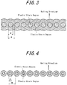
- FIG. 1 schematically illustrates a thermal strain application line in the case where a laser or an electron beam continuously moves over a steel sheet. As illustrated in fig. 1 , the generation of a thermal strain application line forms a plastic strain region and an elastic strain area in a belt like shape. On the other hand, in a case where a thermal strain is applied in a pulse, the above thermal strain application line takes the forms illustrated in figs. 2 , 3, or 4 , depending on the size of the strain regions.
- the steel sheets of the above figs. 1 to 4 exhibit equal iron loss reduction effects obtained by magnetic domain refining. In other words, even if the iron loss reduction effects obtained by magnetic domain refining are equal, steel sheets with different strain distributions are formed.
- the range of these plastic strain regions can be obtained by analyzing data of X-ray diffraction measured from the surface of the steel sheet.
- utilizing the fact that the half value width of X-ray diffraction is increased by non-uniform strain in a plastic strain region, and setting a region where half value width is increased by more than the range of permissible error (i.e. approximately 20 % or more) compared to a point sufficiently distant from the thermal strain application region as the plastic strain region enables quantifying the plastic strain region.
- Length d of each of the above plastic strain region is set to be 0.05 mm or more to 0.4 mm or less. This is because if the length d is shorter than 0.05 mm, a sufficient magnetic domain refinement effect cannot be obtained and iron loss reduction effect is small, whereas if the length d is longer than 0.4 mm, an increase in hysteresis loss, or an increase in noise generated in a transformer is caused.
- the presence ratio can be obtained by a ratio ( ⁇ d/ ⁇ w) when setting a total of the application interval w of each of the plastic strain regions per one thermal strain application line as ⁇ w, and a total of the length d of each of the plastic strain regions per one thermal strain application line as ⁇ d.
- ⁇ d a ratio of the application interval w of each of the plastic strain regions per one thermal strain application line
- ⁇ d a total of the length d of each of the plastic strain regions per one thermal strain application line
- the reason for the limitation of the above presence ratio is that, if the percentage of ( ⁇ d/ ⁇ w) is smaller than 20 %, magnetic domain refinement effect cannot be obtained and iron loss reduction effect is small, whereas if the above percentage is larger than 60 %, the noise generated in a transformer increases. From the perspective of noise suppression, the preferable range of the above percentage is 40 % or less.
- the ratio d/w of each of the above lengths to each of the above application intervals is 0.2 or more and 0.6 or less. This is because if the ratio of each length to each application interval individually satisfies the above range, an even more uniform magnetic domain refining would be applied to the steel sheet compared to the aforementioned case using the ratio between the total values ⁇ d and ⁇ w. Further, in a general equipment for laser irradiation or electron beam irradiation, once the application interval w of a plastic strain region and the length d corresponding to the application interval w of the plastic strain region at one location in a thermal strain application line (see figs. 3 and 4 ) are measured, the strain application line, and the strain application regions (lines) which are further repeatedly formed can be evaluated as having an equal effect in the present invention.
- the above problem is that in a case where the length d is longer than 0.4 mm or a case where the above ratio ( ⁇ d/ ⁇ w) is larger than 0.6, the increase in noise becomes pronounced when worked into a transformer, although there is no significant degradation in magnetic characteristics as a single sheet.
- the difference lies in the fact that steel sheets are stacked and bound in the iron core.
- the fastening force for binding is large in a condition that causes degradation in noise of the transformer.
- the plastic strain region is excessive, a pronounced deflection in the widthwise direction of the steel sheet occurs and, when the deflection is corrected at the time the steel sheet being bound and fixed as an iron core of the transformer, an internal stress is generated in the steel sheet, thereby causing generation of fine magnetic domain as well as an increase in magnetostriction. It is considered that this mechanism causes a pronounced increase in noise.
- a grain-oriented electrical steel sheet of the present invention is preferably a steel sheet that has a texture with an easy magnetization axis in rolling direction (L direction) and constituted with crystal grains with (110)[001] orientation, in order to reduce iron loss.
- L direction an easy magnetization axis of a grain-oriented electrical steel sheet that can actually be industrially manufactured is not completely parallel to rolling direction, but has a deviation angle with respect to rolling direction.
- Bg flux density of when magnetized at 800 A/m
- Bg of the grain-oriented electrical steel sheet used in the present invention is preferably 1.88T or more and more preferably 1.92T or more.
- the surface of the electrical steel sheet is preferable for the surface of the electrical steel sheet to be subjected to tension coating.
- tension coating any conventionally known tension coating may be applied, it is preferable that the glass tension coating contains phosphate and silica as the primary components, such as aluminum phosphate or magnesium phosphate.
- the above described thermal strain application line is preferably linearly formed in the widthwise direction of the steel sheet (direction orthogonal to the rolling direction), and it is preferably repeatedly formed in the rolling direction with an interval of 2 mm or more and 10 mm or less. This is because an increase in iron loss and an increase in transformer noise easily occur with an interval smaller than 2 mm, and the iron loss reduction effect obtained by magnetic domain refining is poor with an interval larger than 10 mm.
- a laser oscillator that oscillates Q switch pulses or normal pulses may be used as an apparatus for applying plastic strain. Further, switching of continuous oscillation, and intermittent irradiation using a chopper is also possible.
- an intermittent plastic strain region can be formed by, switching the beam current on and off, continuously moving the laser while adjusting intensity, repeating movement/stop or high speed movement/low speed movement of the continuously generating electron beam to perform scanning in widthwise direction.
- the chemical composition of a slab for a grain-oriented electrical steel sheet used in the present invention is not particularly limited and any chemical composition that allows secondary recrystallization to proceed may be used.
- the chemical composition may contain appropriate amounts of Al and N in the case where an inhibitor, e.g. an AIN-based inhibitor, is used or appropriate amounts of Mn and Se and/or S in the case where an MnS ⁇ MnSe-based inhibitor is used.
- these inhibitors may also be used in combination.
- preferred contents of Al, N, S and Se are: Al: 0.01 mass% to 0.065 mass%; N: 0.005 mass% to 0.012 mass%; S: 0.005 mass% to 0.03 mass%; and Se: 0.005 mass% to 0.03 mass%, respectively.
- the present invention is also applicable to a grain-oriented electrical steel sheet having limited contents of Al, N, S and Se without using an inhibitor.
- the contents of Al, N, S and Se are preferably limited to Al: 100 mass ppm or less, N: 50 mass ppm or less, S: 50 mass ppm or less, and Se: 50 mass ppm or less, respectively.
- the C content is added for improving the texture of a hot-rolled sheet.
- the C content exceeds 0.08 mass%, it becomes difficult to reduce the C content to 50 mass ppm or less, at which point magnetic aging will not occur during the manufacturing process. Therefore, the C content is preferably 0.08 mass% or less.
- Si is an element that is effective for enhancing electrical resistance of steel and improving iron loss properties thereof. However, if the content is less than 2.0 mass%, a sufficient iron loss reduction effect cannot be achieved. On the other hand, Si content above 8.0 mass% significantly deteriorates formability and also decreases the flux density of the steel. Therefore, the Si content is preferably in a range of 2.0 mass% to 8.0 mass%.
- Mn is a necessary element for achieving better hot workability of steel. However, this effect is poor when the Mn content in steel is below 0.005 mass%. On the other hand, Mn content in steel exceeding 1.0 mass% deteriorates magnetic flux of a product steel sheet. Therefore, the Mn content is preferably in a range of 0.005 mass% to 1.0 mass%.
- the slab may also contain the following as elements for improving magnetic properties as deemed appropriate: At least one element selected from Ni: 0.03 mass% to 1.50 mass%, Sn: 0.01 mass% to 1.50 mass%, Sb: 0.005 mass% to 1.50 mass%, Cu: 0.03 mass% to 3.0 mass%, P: 0.03 mass% to 0.50 mass%, and Mo: 0.005 mass% to 0.10 mass%
- Ni is an element that is useful for improving the texture of a hot rolled steel sheet for better magnetic properties thereof.
- Ni content in steel below 0.03 mass% is less effective for improving magnetic properties, while Ni content in steel above 1.50 mass% makes secondary recrystallization of the steel unstable, thereby deteriorating the magnetic properties thereof. Therefore, Ni content is preferably in a range of 0.03 mass% to 1.50 mass%.
- Sn, Sb, Cu, P, Cr, and Mo are each useful elements in terms of improving magnetic properties of steel.
- each of these elements becomes less effective for improving magnetic properties of the steel when contained in steel in an amount less than the aforementioned lower limit and inhibits the growth of secondary recrystallized grains of the steel when contained in steel in an amount exceeding the aforementioned upper limit. Therefore, each of these elements is preferably contained within the respective ranges thereof specified above.
- the balance other than the above-described elements is Fe and incidental impurities that are incorporated during the manufacturing process.
- the slab having the above described chemical composition is subjected to heating before hot rolling in a conventional manner.
- the slab may also be subjected to hot rolling directly after casting, without being subjected to heating.
- it may be subjected to hot rolling or directly proceed to the subsequent step, omitting hot rolling.
- hot band annealing temperature is preferably in the range of 800 ° C to 1100 ° C. If the hot band annealing temperature is lower than 800 ° C, there remains a band texture resulting from hot rolling, which makes it difficult to obtain a primary recrystallization texture of uniformly sized grains and impedes the growth of secondary recrystallization. On the other hand, if the hot band annealing temperature exceeds 1100 °C, the grain size after the hot band annealing coarsens too much, which makes it extremely difficult to obtain a primary recrystallization texture of uniformly-sized grains.
- the sheet After the hot band annealing, the sheet is subjected to cold rolling once, or twice or more with intermediate annealing performed therebetween, followed by recrystallization annealing and application of an annealing separator to the sheet. After the application of the annealing separator, the sheet is subjected to final annealing for purposes of secondary recrystallization and formation of a forsterite film.
- the steel sheet After the final annealing, it is effective to subject the steel sheet to flattening annealing to correct the shape thereof. In the case of stacking steel sheets for use, it is effective to apply tension coating to the surface of the steel sheets before or after the flattening annealing, for the purpose of improving iron loss properties.
- a conventionally known method for manufacturing a grain-oriented electrical steel sheet may be used as appropriate.
- a single sheet sample with a width of 100 mm and a length of 400 mm was cut out from the coil and subjected to magnetic domain refining treatment by irradiating a Q-switched pulse oscillation fiber laser.
- the beam diameter of the laser was changed in the range of 0.05 to 0.6 mm by defocusing, and the repeating interval in widthwise direction was set to 0.1 to 1.2 mm, to search for the power which most reduces iron loss.
- the width of the plastic strain region was enlarged by enlarging the beam diameter and increasing the beam power so that sufficient thermal strain is applied in accordance with the increase of area. Further, by increasing and decreasing the holding time of beam irradiation at one location, the size of the elastic strain region was controlled.
- the repeating interval in rolling direction of the strain regions was set to 4.5 mm.
- the distribution in widthwise direction of the plastic strain region in the strain region was obtained by measuring the half value width of the diffraction peak of the ⁇ -fe ⁇ 112 ⁇ plane by X-ray diffraction using a Cr-K ⁇ X-ray.
- the iron core is an iron core of stacked three-phase tripod type with a leg width of 150 mm and weight of 900 kg.
- the transformer is an oil immersed transformer with a capacity of 1000kVA.
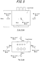
- Flux density of the iron core was exited to 1.7T at 50Hz, and no-load loss was measured and defined as the value of iron loss. Further, as illustrated in fig. 5 , noise was measured 30 cm from the outer surface of the transformer in front, back, left and right of it to obtain the average value. [Table 1] No.
- Magnetic domain refining was performed by irradiating electron beam to a coil of the same grain-oriented electrical steel sheet as example 1.
- Electron beam irradiation was performed with an acceleration voltage of 60 kV and beam diameter of 0.25 mm. Irradiation was stopped at one location for 10 ms, and then moved to the next irradiation point with the repeating interval set to 0.34 mm and 0.5 mm. Other conditions of the irradiation were as described in table 2. Further, a condition where the width of the plastic strain region is 0.2 mm and the iron loss is minimized was searched. An iron core of a transformer was manufactured using the condition, in the same manner as example 1, and iron loss and noise were tested. [Table 2] No.
- iron loss value was smaller by 22W or more in coils irradiated with electron beam, as shown in table 2.
Description
- The present invention relates to a grain-oriented electrical steel sheet utilized for an iron core material of a transformer or the like.
- In recent years, energy use has become more and more efficient, and demands are increasingly being made, mainly from transformer manufacturers and the like, for an electrical steel sheet with high flux density and low iron loss.
- The flux density can be improved by according crystal orientations of the electrical steel sheet with the Goss orientation.
- With regards to iron loss reduction, measures have been devised from the perspectives of increasing purity of the material, high orientation, reduced sheet thickness, addition of Si and Al, magnetic domain refining, and the like. However, iron loss properties generally tend to worsen as the flux density is higher. The reason is that when the crystal orientations are aligned, the magnetostatic energy decreases, and therefore the magnetic domain width widens, causing eddy current loss to rise.
- One solution to this problem is to reduce eddy current loss. Specific methods include a method of applying magnetic domain refining by applying thermal strain to the surface of a steel sheet, and a method using laser or electron beam. Both methods are known to exhibit an extremely high improving effect in iron loss by irradiation.
- For example,
JPH7-65106B2 - Furthermore,
JPH3-13293B2 - PTL 3, PTL 4 and PTL 5 disclose grain-oriented electrical steel sheets with irratiation marks.
-
- PTL 1:
JPH7-65106B2 - PTL 2:
JPH3-13293B2 - PTL3:
EP2602347 A1 - PTL 4:
EP2799566 A1 - PTL 5:
JP2003-034822 A - However, although grain-oriented electrical steel sheets subjected to magnetic domain refining by irradiating laser or electron beam may show good characteristics as a material, there are cases where good characteristics cannot be obtained when manufacturing a transformer using the same grain-oriented electrical steel sheet. Specifically, the problem is that the noise of the transformer increases. In other words, even if iron loss, flux density, magnetostriction etc. measured in the state of a single sheet material are the same, some conditions produce transformers with a loud noise and some conditions produce transformers with a small noise, depending on the pattern of applying thermal strain.
- The present invention has been developed in light of the above circumstances, and it is an object thereof to provide a grain-oriented electrical steel sheet that is capable of effectively reducing the noise caused by the grain-oriented electrical steel sheet when worked into a transformer.
- The inventors of the present invention prepared transformers of many grain-oriented electrical steel sheets subjected to magnetic domain refining treatment with different patterns of applying thermal strain, and conducted a systematic investigation. As a result, the inventors discovered that the increase in noise of the transformer is caused by the shape of the region where plastic strain is generated when thermal strain is applied in a strong degree.
- Additionally, the pattern of applying strain can be divided into 2 types, namely, a continuous pattern in the widthwise direction of the steel sheet such as continuous laser irradiation, and an intermittent pattern in the widthwise direction of the steel sheet such as pulse laser irradiation. It was discovered that it is possible to achieve both iron loss reduction and noise suppression of the transformer particularly when the area of the plastic strain regions at the time of application of intermittent strain regions, and the ratio that the area of the plastic strain regions occupies in the widthwise direction of the steel sheet, are in a certain range.
- The present invention is based on the above discoveries.
- Specifically, the primary features of the present invention are as described in the appended claim and is as follows:
- 1. A grain-oriented electrical steel sheet to which plastic strain regions are applied in a dot-sequence manner in widthwise direction of the steel sheet by magnetic domain refining treatment, wherein a length d of each of the plastic strain regions in the widthwise direction of the steel sheet is 0.05 mm or more and 0.4 mm or less, and a ratio (∑d/∑w) of a total ∑d of the length d to a total ∑w of an application interval w of each of the plastic strain regions is 0.2 or more and 0.6 or less, wherein a ratio (d/w) of the length d of each of the plastic strain regions to the application interval w corresponding to the length d of each of the plastic strain regions is 0.2 or more and 0.6 or less, wherein the length d is obtained by measuring the half value width of the diffraction peak of the α-fe {112} plane by X-ray diffraction using a Cr-Kα X-ray, and wherein the plastic strain region is a region where the half value width is increased by 20% or more compared to the position located 2 mm away in rolling direction from the beam irradiation position.
- According to the present invention, it is possible to suppress the increase in noise of a transformer and at the same time reduce iron loss of the transformer, when performing magnetic domain refining of the grain-oriented electrical steel sheet. Therefore, energy efficiency of a transformer is enhanced, and the invention is extremely useful in the industry.
- The present invention will be further described below with reference to the accompanying drawings, wherein:
-
FIG. 1 is a schematic diagram illustrating an example of an embodiment of a plastic strain region and elastic strain regions; -
FIG. 2 is a schematic diagram illustrating another example of an embodiment of a plastic strain region and elastic strain regions; -
FIG. 3 is a schematic diagram illustrating an example of an embodiment of plastic strain regions and an elastic strain region according to the present invention; -
FIG. 4 is a schematic diagram illustrating another example of an embodiment of plastic strain regions and elastic strain regions according to the present invention; and -
FIG. 5 illustrates the procedures for measuring noise of a transformer. - The following describes the present invention in detail.
- In the present invention, strain regions are applied to a grain-oriented electrical steel sheet from one end to the other in the width direction of the steel sheet in a linear or curved manner, or in a direction orthogonal to the rolling direction in a dot-sequence manner. Strain region(s) generated in such way are hereinafter referred to as a "thermal strain application line". This thermal strain application line is periodically applied in rolling direction, to generate a magnetic domain pattern.
- In the present invention, each of the plural thermal strain application lines periodically applied in rolling direction is applied in a direction orthogonal to the rolling direction (a preferable range is ±30° to the direction orthogonal to the rolling direction), and magnetic domain refining treatment is performed in a desirable area of the steel sheet.
- To perform application of strain regions in accordance with the present invention, heat/ light/ particle beam irradiation such as laser irradiation, electron beam irradiation, plasma flame irradiation where local and rapid heating is possible, can be used. From the perspective of controllability of the shape and size of strain regions, laser and electron beams which enable controlling the beam diameter to be small, are preferred.
- By applying laser irradiation or electron beam irradiation, the surface of a steel sheet is rapidly heated and thermal expansion is caused. However, since the heating time is extremely short, the region which is heated to a high temperature is limited to a local area. The local area is restrained by a surrounding non-heated region, and therefore the location where thermal strain is applied receives a large compressive stress, and causes generation of a plastic strain.
- This plastic strain remains after being cooled to room temperature and forms an elastic stress field in the surrounding area.
Fig. 1 schematically illustrates a thermal strain application line in the case where a laser or an electron beam continuously moves over a steel sheet. As illustrated infig. 1 , the generation of a thermal strain application line forms a plastic strain region and an elastic strain area in a belt like shape. On the other hand, in a case where a thermal strain is applied in a pulse, the above thermal strain application line takes the forms illustrated infigs. 2 ,3, or 4 , depending on the size of the strain regions. - In other words, depending on irradiation conditions of laser or electron beam, different strain distributions as illustrated in
figs. 1 to 4 are formed. - Here, from the perspective of iron loss, the steel sheets of the above
figs. 1 to 4 exhibit equal iron loss reduction effects obtained by magnetic domain refining. In other words, even if the iron loss reduction effects obtained by magnetic domain refining are equal, steel sheets with different strain distributions are formed. - The range of these plastic strain regions can be obtained by analyzing data of X-ray diffraction measured from the surface of the steel sheet. In other words, utilizing the fact that the half value width of X-ray diffraction is increased by non-uniform strain in a plastic strain region, and setting a region where half value width is increased by more than the range of permissible error (i.e. approximately 20 % or more) compared to a point sufficiently distant from the thermal strain application region as the plastic strain region enables quantifying the plastic strain region.
- From the results of tests conducted by the inventors for examining characteristics of a transformer manufactured from a grain-oriented electrical steel sheet having various types of strain distribution, it has been identified that both iron loss reduction and noise suppression can be achieved in a case where the plastic strain region is in an intermittent distribution as shown in
figs 3 and 4 with the ratio d/w of the size of length d of the plastic strain region illustrated in the figures and application interval w of plastic strain region illustrated in the figures being in a particular range. Further, among the cases where thermal strain was applied in a pulse, the form offig. 2 where the plastic strain region was continuously applied exhibited a poor noise suppressing effect. - In addition, it has also been identified that, even in a case where the resultant steel sheets have equal strain distributions, lower iron loss can be obtained by electron beam irradiation compared to laser irradiation.
- Length d of each of the above plastic strain region is set to be 0.05 mm or more to 0.4 mm or less. This is because if the length d is shorter than 0.05 mm, a sufficient magnetic domain refinement effect cannot be obtained and iron loss reduction effect is small, whereas if the length d is longer than 0.4 mm, an increase in hysteresis loss, or an increase in noise generated in a transformer is caused.
- Further, as described previously, it is important that the plastic strain region is applied in an intermittent distribution, in the present invention. The presence ratio can be obtained by a ratio (∑d/∑w) when setting a total of the application interval w of each of the plastic strain regions per one thermal strain application line as ∑w, and a total of the length d of each of the plastic strain regions per one thermal strain application line as ∑d. Here it is crucial to set the value to 0.2 or more and 0.6 or less. When expressed in percentage, the value is 20 % or more and 60 % or less.
- The reason for the limitation of the above presence ratio is that, if the percentage of (∑d/∑w) is smaller than 20 %, magnetic domain refinement effect cannot be obtained and iron loss reduction effect is small, whereas if the above percentage is larger than 60 %, the noise generated in a transformer increases. From the perspective of noise suppression, the preferable range of the above percentage is 40 % or less.
- Further, in the present invention, the ratio d/w of each of the above lengths to each of the above application intervals is 0.2 or more and 0.6 or less. This is because if the ratio of each length to each application interval individually satisfies the above range, an even more uniform magnetic domain refining would be applied to the steel sheet compared to the aforementioned case using the ratio between the total values ∑d and ∑w. Further, in a general equipment for laser irradiation or electron beam irradiation, once the application interval w of a plastic strain region and the length d corresponding to the application interval w of the plastic strain region at one location in a thermal strain application line (see
figs. 3 and 4 ) are measured, the strain application line, and the strain application regions (lines) which are further repeatedly formed can be evaluated as having an equal effect in the present invention. - While the reason why noise generated in a transformer can be reduced by controlling the form of the region where plastic strain is generated is not clear, the inventors think as follows.
- The above problem is that in a case where the length d is longer than 0.4 mm or a case where the above ratio (∑d/∑w) is larger than 0.6, the increase in noise becomes pronounced when worked into a transformer, although there is no significant degradation in magnetic characteristics as a single sheet.
- When considering the difference between a single sheet and an iron core of a transformer, the difference lies in the fact that steel sheets are stacked and bound in the iron core. In particular, the fastening force for binding is large in a condition that causes degradation in noise of the transformer. According to this fact, in a case where the plastic strain region is excessive, a pronounced deflection in the widthwise direction of the steel sheet occurs and, when the deflection is corrected at the time the steel sheet being bound and fixed as an iron core of the transformer, an internal stress is generated in the steel sheet, thereby causing generation of fine magnetic domain as well as an increase in magnetostriction. It is considered that this mechanism causes a pronounced increase in noise.
- Even in a case where a plastic strain region with the same size is formed on the surface of the steel sheet, it would be possible to reduce more iron loss of a transformer by electron beam irradiation than by laser irradiation.
- It is considered that this is because while a laser which is a light heats only the surface of the steel sheet, an electron beam enters the steel sheet to heat it and forms a plastic strain region and a elastic strain region in a deeper region compared to a laser.
- A grain-oriented electrical steel sheet of the present invention is preferably a steel sheet that has a texture with an easy magnetization axis in rolling direction (L direction) and constituted with crystal grains with (110)[001] orientation, in order to reduce iron loss. However, an easy magnetization axis of a grain-oriented electrical steel sheet that can actually be industrially manufactured is not completely parallel to rolling direction, but has a deviation angle with respect to rolling direction. Further, in order to reduce iron loss by magnetic domain refining of the grain-oriented electrical steel sheet, it is considered to be effective to form a strain region or strain regions made from tensile residual stress and plastic strain on the surface of the steel sheet continuously or at a predetermined interval, in the magnetization direction, i.e., in the orthogonal direction to the easy magnetization axis.
- With respect to a grain-oriented electrical steel sheet subjected to magnetic domain refining treatment, it is known that higher orientation integration of secondary recrystallization results in smaller magnetic domains. Bg (flux density of when magnetized at 800 A/m) is frequently used as an indication of orientation integration. Bg of the grain-oriented electrical steel sheet used in the present invention is preferably 1.88T or more and more preferably 1.92T or more.
- Further, it is preferable for the surface of the electrical steel sheet to be subjected to tension coating. Although any conventionally known tension coating may be applied, it is preferable that the glass tension coating contains phosphate and silica as the primary components, such as aluminum phosphate or magnesium phosphate.
- The above described thermal strain application line is preferably linearly formed in the widthwise direction of the steel sheet (direction orthogonal to the rolling direction), and it is preferably repeatedly formed in the rolling direction with an interval of 2 mm or more and 10 mm or less. This is because an increase in iron loss and an increase in transformer noise easily occur with an interval smaller than 2 mm, and the iron loss reduction effect obtained by magnetic domain refining is poor with an interval larger than 10 mm.
- In the case of laser irradiation, a laser oscillator that oscillates Q switch pulses or normal pulses may be used as an apparatus for applying plastic strain. Further, switching of continuous oscillation, and intermittent irradiation using a chopper is also possible. In the case of electron beam irradiation, an intermittent plastic strain region can be formed by, switching the beam current on and off, continuously moving the laser while adjusting intensity, repeating movement/stop or high speed movement/low speed movement of the continuously generating electron beam to perform scanning in widthwise direction.
- The chemical composition of a slab for a grain-oriented electrical steel sheet used in the present invention is not particularly limited and any chemical composition that allows secondary recrystallization to proceed may be used.
- Further, the chemical composition may contain appropriate amounts of Al and N in the case where an inhibitor, e.g. an AIN-based inhibitor, is used or appropriate amounts of Mn and Se and/or S in the case where an MnS·MnSe-based inhibitor is used. Of course, these inhibitors may also be used in combination. In this case, preferred contents of Al, N, S and Se are: Al: 0.01 mass% to 0.065 mass%; N: 0.005 mass% to 0.012 mass%; S: 0.005 mass% to 0.03 mass%; and Se: 0.005 mass% to 0.03 mass%, respectively.
- Furthermore, the present invention is also applicable to a grain-oriented electrical steel sheet having limited contents of Al, N, S and Se without using an inhibitor.
- In this case, the contents of Al, N, S and Se are preferably limited to Al: 100 mass ppm or less, N: 50 mass ppm or less, S: 50 mass ppm or less, and Se: 50 mass ppm or less, respectively.
- Additionally, specific basic components and optionally added components of a slab for the grain-oriented electrical steel sheet of the present invention are as follows.
- C is added for improving the texture of a hot-rolled sheet. However, if the C content exceeds 0.08 mass%, it becomes difficult to reduce the C content to 50 mass ppm or less, at which point magnetic aging will not occur during the manufacturing process. Therefore, the C content is preferably 0.08 mass% or less. Besides, it is not necessary to set a particular lower limit to the C content because secondary recrystallization is enabled by a material not containing C.
- Si is an element that is effective for enhancing electrical resistance of steel and improving iron loss properties thereof. However, if the content is less than 2.0 mass%, a sufficient iron loss reduction effect cannot be achieved. On the other hand, Si content above 8.0 mass% significantly deteriorates formability and also decreases the flux density of the steel. Therefore, the Si content is preferably in a range of 2.0 mass% to 8.0 mass%.
- Mn is a necessary element for achieving better hot workability of steel. However, this effect is poor when the Mn content in steel is below 0.005 mass%. On the other hand, Mn content in steel exceeding 1.0 mass% deteriorates magnetic flux of a product steel sheet. Therefore, the Mn content is preferably in a range of 0.005 mass% to 1.0 mass%.
- Furthermore, in addition to the above basic components, the slab may also contain the following as elements for improving magnetic properties as deemed appropriate:
At least one element selected from Ni: 0.03 mass% to 1.50 mass%, Sn: 0.01 mass% to 1.50 mass%, Sb: 0.005 mass% to 1.50 mass%, Cu: 0.03 mass% to 3.0 mass%, P: 0.03 mass% to 0.50 mass%, and Mo: 0.005 mass% to 0.10 mass% - Ni is an element that is useful for improving the texture of a hot rolled steel sheet for better magnetic properties thereof. However, Ni content in steel below 0.03 mass% is less effective for improving magnetic properties, while Ni content in steel above 1.50 mass% makes secondary recrystallization of the steel unstable, thereby deteriorating the magnetic properties thereof. Therefore, Ni content is preferably in a range of 0.03 mass% to 1.50 mass%.
- In addition, Sn, Sb, Cu, P, Cr, and Mo are each useful elements in terms of improving magnetic properties of steel. However, each of these elements becomes less effective for improving magnetic properties of the steel when contained in steel in an amount less than the aforementioned lower limit and inhibits the growth of secondary recrystallized grains of the steel when contained in steel in an amount exceeding the aforementioned upper limit. Therefore, each of these elements is preferably contained within the respective ranges thereof specified above.
- The balance other than the above-described elements is Fe and incidental impurities that are incorporated during the manufacturing process.
- Next, the slab having the above described chemical composition is subjected to heating before hot rolling in a conventional manner. However, the slab may also be subjected to hot rolling directly after casting, without being subjected to heating. In the case of a thin slab or thinner cast steel, it may be subjected to hot rolling or directly proceed to the subsequent step, omitting hot rolling.
- Furthermore, the hot rolled sheet is optionally subjected to hot band annealing. At this time, in order to obtain a highly-developed Goss texture in a product sheet, hot band annealing temperature is preferably in the range of 800 ° C to 1100 ° C. If the hot band annealing temperature is lower than 800 ° C, there remains a band texture resulting from hot rolling, which makes it difficult to obtain a primary recrystallization texture of uniformly sized grains and impedes the growth of secondary recrystallization. On the other hand, if the hot band annealing temperature exceeds 1100 °C, the grain size after the hot band annealing coarsens too much, which makes it extremely difficult to obtain a primary recrystallization texture of uniformly-sized grains.
- After the hot band annealing, the sheet is subjected to cold rolling once, or twice or more with intermediate annealing performed therebetween, followed by recrystallization annealing and application of an annealing separator to the sheet. After the application of the annealing separator, the sheet is subjected to final annealing for purposes of secondary recrystallization and formation of a forsterite film.
- After the final annealing, it is effective to subject the steel sheet to flattening annealing to correct the shape thereof. In the case of stacking steel sheets for use, it is effective to apply tension coating to the surface of the steel sheets before or after the flattening annealing, for the purpose of improving iron loss properties.
- In the present invention, other than the above-described steps and manufacturing conditions, a conventionally known method for manufacturing a grain-oriented electrical steel sheet may be used as appropriate.
- Further, it is also possible to use a grain-oriented electrical steel sheet to which a technique of reducing hysteresis loss by smoothening the steel sheet surface without forming a forsterite film thereon, is applied.
- A coil of a grain-oriented electrical steel sheet having a sheet thickness of 0.23 mm and flux density B8 in rolling direction of 1.94T, and having 2 layers of coating, namely a coating containing forsterite as the primary component and a coating (silica/ phosphate based coating) formed by baking a coating solution of inorganic substance thereon, on the surface of the steel substrate, was prepared.
- First, a single sheet sample with a width of 100 mm and a length of 400 mm was cut out from the coil and subjected to magnetic domain refining treatment by irradiating a Q-switched pulse oscillation fiber laser. The beam diameter of the laser was changed in the range of 0.05 to 0.6 mm by defocusing, and the repeating interval in widthwise direction was set to 0.1 to 1.2 mm, to search for the power which most reduces iron loss.
- Here, the width of the plastic strain region was enlarged by enlarging the beam diameter and increasing the beam power so that sufficient thermal strain is applied in accordance with the increase of area. Further, by increasing and decreasing the holding time of beam irradiation at one location, the size of the elastic strain region was controlled.
- Further, the repeating interval in rolling direction of the strain regions was set to 4.5 mm.
- The distribution in widthwise direction of the plastic strain region in the strain region was obtained by measuring the half value width of the diffraction peak of the α-fe {112} plane by X-ray diffraction using a Cr-Kα X-ray. The region where the half value width is increased by 20% or more compared to the position located 2 mm away in rolling direction from the beam irradiation position, was defined as the plastic strain region.
- Next, laser irradiation was performed on the overall width of the coil with the optimum beam power obtained in the above study to manufacture the coil for iron core material. Further, this coil was used as an iron core material to prepare a transformer. The iron core is an iron core of stacked three-phase tripod type with a leg width of 150 mm and weight of 900 kg. The transformer is an oil immersed transformer with a capacity of 1000kVA.
- Flux density of the iron core was exited to 1.7T at 50Hz, and no-load loss was measured and defined as the value of iron loss. Further, as illustrated in
fig. 5 , noise was measured 30 cm from the outer surface of the transformer in front, back, left and right of it to obtain the average value.[Table 1] No. Length d of Plastic Strain Region (mm) Introduction Interval w of Plastic Strain Region (mm) Ratio of d to w d/w×100(%) Iron Loss of Transformer (W) Noise of Transformer (dB) Remarks 1 0.05 0.15 33 787 52 Inventive Example 2 0.2 0.34 59 777 53 Inventive Example 3 0.2 0.5 40 778 52 Inventive Example 4 0.2 1.0 20 788 52 Inventive Example 5 0.4 0.7 57 788 52 Inventive Example 6 0.04 0.08 50 834 57 Comparative Example 7 0.2 0.32 63 799 56 Comparative Example 8 0.2 1.2 17 844 53 Comparative Example 9 0.5 0.85 59 833 56 Comparative Example - As shown in table 1, excellent characteristics with iron loss of 630 W or less and transformer noise of 53dB or less, were obtained in a condition within the range of the present invention.
- Magnetic domain refining was performed by irradiating electron beam to a coil of the same grain-oriented electrical steel sheet as example 1.
- Electron beam irradiation was performed with an acceleration voltage of 60 kV and beam diameter of 0.25 mm. Irradiation was stopped at one location for 10 ms, and then moved to the next irradiation point with the repeating interval set to 0.34 mm and 0.5 mm. Other conditions of the irradiation were as described in table 2. Further, a condition where the width of the plastic strain region is 0.2 mm and the iron loss is minimized was searched. An iron core of a transformer was manufactured using the condition, in the same manner as example 1, and iron loss and noise were tested.
[Table 2] No. Method of Magnetic Domain Refining Treatment Length d of Plastic Strain Region (mm) Application Interval w of Plastic Strain Region (mm) Ratio of d to w d/w×100(%) Iron Loss of Transformer (W) Noise of Transformer (dB) Remarks 1 Electron Beam 0.2 0.34 59 754 53 Inventive Example 2 Electron Beam 0.2 0.50 40 755 52 Inventive Example 3 Laser 0.2 0.34 59 777 53 Inventive Example 4 Laser 0.2 0.50 40 778 52 Inventive Example - When comparing with laser irradiation of example 1, iron loss value was smaller by 22W or more in coils irradiated with electron beam, as shown in table 2.
Claims (1)
- A grain-oriented electrical steel sheet to which plastic strain regions are applied in a dot-sequence manner in widthwise direction of the steel sheet by magnetic domain refining treatment, wherein
a length d of each of the plastic strain regions in the widthwise direction of the steel sheet is 0.05 mm or more and 0.4 mm or less,
a ratio (∑d/∑w) of a total ∑d of the length d to a total ∑w of an application interval w of each of the plastic strain regions is 0.2 or more and 0.6 or less,
wherein a ratio (d/w) of the length d of each of the plastic strain regions to the application interval w corresponding to the length d of each of the plastic strain regions is 0.2 or more and 0.6 or less, wherein
the length d is obtained by measuring the half value width of the diffraction peak of the α-fe {112} plane by X-ray diffraction using a Cr-Kα X-ray, and wherein
the plastic strain region is a region where the half value width is increased by 20% or more compared to the position located 2 mm away in rolling direction from the beam irradiation position.
Applications Claiming Priority (2)
| Application Number | Priority Date | Filing Date | Title |
|---|---|---|---|
| JP2012025238A JP6007501B2 (en) | 2012-02-08 | 2012-02-08 | Oriented electrical steel sheet |
| PCT/JP2013/000701 WO2013118512A1 (en) | 2012-02-08 | 2013-02-08 | Grain-oriented electrical steel plate |
Publications (3)
| Publication Number | Publication Date |
|---|---|
| EP2813593A1 EP2813593A1 (en) | 2014-12-17 |
| EP2813593A4 EP2813593A4 (en) | 2015-11-11 |
| EP2813593B1 true EP2813593B1 (en) | 2020-04-08 |
Family
ID=48947282
Family Applications (1)
| Application Number | Title | Priority Date | Filing Date |
|---|---|---|---|
| EP13746080.4A Active EP2813593B1 (en) | 2012-02-08 | 2013-02-08 | Grain-oriented electrical steel plate |
Country Status (7)
| Country | Link |
|---|---|
| US (1) | US9761361B2 (en) |
| EP (1) | EP2813593B1 (en) |
| JP (1) | JP6007501B2 (en) |
| KR (1) | KR101633207B1 (en) |
| CN (1) | CN104105808B (en) |
| RU (1) | RU2570591C1 (en) |
| WO (1) | WO2013118512A1 (en) |
Families Citing this family (10)
| Publication number | Priority date | Publication date | Assignee | Title |
|---|---|---|---|---|
| CN104011241B (en) | 2011-12-22 | 2016-06-29 | 杰富意钢铁株式会社 | Orientation electromagnetic steel plate and manufacture method thereof |
| WO2018159390A1 (en) * | 2017-02-28 | 2018-09-07 | Jfeスチール株式会社 | Grain-oriented electrical steel sheet and production method therefor |
| KR102360385B1 (en) * | 2018-01-31 | 2022-02-08 | 제이에프이 스틸 가부시키가이샤 | Grain-oriented electrical steel sheet and method for manufacturing the wound iron core and the wound iron core of a transformer made using the same |
| EP3734623A4 (en) * | 2018-01-31 | 2021-03-10 | JFE Steel Corporation | Grain-oriented electrical steel sheet, transformer stacked core using same, and method for producing stacked core |
| CN109490346B (en) * | 2018-10-15 | 2021-07-02 | 内蒙古科技大学 | Method for measuring orientation deviation angle of oriented silicon steel through X-ray diffraction |
| CN113348257B (en) * | 2019-01-28 | 2023-04-14 | 日本制铁株式会社 | Grain-oriented electromagnetic steel sheet and method for producing same |
| US11121592B2 (en) | 2019-04-08 | 2021-09-14 | GM Global Technology Operations LLC | Electric machine core with arcuate grain orientation |
| EP3985134A4 (en) | 2019-06-17 | 2022-06-29 | JFE Steel Corporation | Grain-oriented electromagnetic steel plate and production method therefor |
| MX2022007347A (en) * | 2019-12-25 | 2022-07-19 | Jfe Steel Corp | Grain-oriented electromagnetic steel sheet and production method therefor. |
| WO2023038428A1 (en) | 2021-09-09 | 2023-03-16 | 엘지전자 주식회사 | Display device, vehicle having same, and control method for vehicle |
Family Cites Families (26)
| Publication number | Priority date | Publication date | Assignee | Title |
|---|---|---|---|---|
| US4363677A (en) * | 1980-01-25 | 1982-12-14 | Nippon Steel Corporation | Method for treating an electromagnetic steel sheet and an electromagnetic steel sheet having marks of laser-beam irradiation on its surface |
| JPS5850298B2 (en) * | 1980-01-25 | 1983-11-09 | 新日本製鐵株式会社 | Processing method for electrical steel sheets |
| JPS5836053B2 (en) * | 1981-05-19 | 1983-08-06 | 新日本製鐵株式会社 | Processing method for electrical steel sheets |
| JPS5819440A (en) | 1981-07-24 | 1983-02-04 | Nippon Steel Corp | Method for improving watt loss characteristic of electromagnetic steel pipe |
| JPH0191744A (en) * | 1987-10-01 | 1989-04-11 | Morita Sangyo Kk | Far infrared radiator for heating tea leaves |
| JPH01191744A (en) * | 1988-01-26 | 1989-08-01 | Nippon Steel Corp | Manufacture of grain-oriented electrical steel sheet with low iron loss |
| JPH0699823B2 (en) * | 1988-02-16 | 1994-12-07 | 川崎製鉄株式会社 | Method for manufacturing ultra low iron loss unidirectional silicon steel sheet |
| JP2638180B2 (en) * | 1988-10-26 | 1997-08-06 | 川崎製鉄株式会社 | Low iron loss unidirectional silicon steel sheet and method for producing the same |
| JPH0765106B2 (en) | 1988-10-26 | 1995-07-12 | 川崎製鉄株式会社 | Method for manufacturing low iron loss unidirectional silicon steel sheet |
| JP2719832B2 (en) | 1989-06-09 | 1998-02-25 | ユーホーケミカル株式会社 | Solder paste |
| JPH0765108B2 (en) * | 1990-03-09 | 1995-07-12 | 川崎製鉄株式会社 | Iron loss reduction method of unidirectional silicon steel sheet by electron beam irradiation |
| KR940008459B1 (en) * | 1992-04-08 | 1994-09-15 | 포항종합제철 주식회사 | Method of manufacturing electro-magnetic steel plate |
| KR940008459A (en) | 1992-09-07 | 1994-04-29 | 박경팔 | television |
| DE69331221T2 (en) | 1993-02-15 | 2002-05-23 | Kawasaki Steel Co | Process for the production of low-noise grain-oriented silicon steel sheets with low watt losses and with excellent shape properties |
| JPH0765106A (en) | 1993-08-25 | 1995-03-10 | Fuji Electric Co Ltd | Bar code reader |
| WO1997024466A1 (en) | 1995-12-27 | 1997-07-10 | Nippon Steel Corporation | Magnetic steel sheet having excellent magnetic properties and method for manufacturing the same |
| JP4598321B2 (en) * | 2001-07-26 | 2010-12-15 | 新日本製鐵株式会社 | Oriented electrical steel sheet with excellent magnetic properties |
| JP2005226122A (en) * | 2004-02-13 | 2005-08-25 | Nippon Steel Corp | System and method for manufacturing grain-oriented electromagnetic steel sheet, and device for predicting magnetic properties |
| TWI305548B (en) * | 2005-05-09 | 2009-01-21 | Nippon Steel Corp | Low core loss grain-oriented electrical steel sheet and method for producing the same |
| JP5000182B2 (en) * | 2006-04-07 | 2012-08-15 | 新日本製鐵株式会社 | Method for producing grain-oriented electrical steel sheet with excellent magnetic properties |
| RU2398894C1 (en) * | 2006-06-16 | 2010-09-10 | Ниппон Стил Корпорейшн | Sheet of high strength electro-technical steel and procedure for its production |
| JP5613972B2 (en) * | 2006-10-23 | 2014-10-29 | 新日鐵住金株式会社 | Unidirectional electrical steel sheet with excellent iron loss characteristics |
| JP5696380B2 (en) | 2010-06-30 | 2015-04-08 | Jfeスチール株式会社 | Iron loss improvement device and iron loss improvement method for grain-oriented electrical steel sheet |
| JP5593942B2 (en) * | 2010-08-06 | 2014-09-24 | Jfeスチール株式会社 | Oriented electrical steel sheet and manufacturing method thereof |
| JP5919617B2 (en) * | 2010-08-06 | 2016-05-18 | Jfeスチール株式会社 | Oriented electrical steel sheet and manufacturing method thereof |
| US10062483B2 (en) | 2011-12-28 | 2018-08-28 | Jfe Steel Corporation | Grain-oriented electrical steel sheet and method for improving iron loss properties thereof |
-
2012
- 2012-02-08 JP JP2012025238A patent/JP6007501B2/en active Active
-
2013
- 2013-02-08 EP EP13746080.4A patent/EP2813593B1/en active Active
- 2013-02-08 US US14/376,916 patent/US9761361B2/en active Active
- 2013-02-08 WO PCT/JP2013/000701 patent/WO2013118512A1/en active Application Filing
- 2013-02-08 RU RU2014136395/02A patent/RU2570591C1/en active
- 2013-02-08 CN CN201380008689.6A patent/CN104105808B/en active Active
- 2013-02-08 KR KR1020147024613A patent/KR101633207B1/en active IP Right Grant
Non-Patent Citations (1)
| Title |
|---|
| None * |
Also Published As
| Publication number | Publication date |
|---|---|
| JP6007501B2 (en) | 2016-10-12 |
| EP2813593A1 (en) | 2014-12-17 |
| CN104105808B (en) | 2017-02-22 |
| KR101633207B1 (en) | 2016-06-23 |
| WO2013118512A8 (en) | 2014-07-17 |
| KR20140133838A (en) | 2014-11-20 |
| US20150013849A1 (en) | 2015-01-15 |
| EP2813593A4 (en) | 2015-11-11 |
| RU2570591C1 (en) | 2015-12-10 |
| JP2013159846A (en) | 2013-08-19 |
| WO2013118512A1 (en) | 2013-08-15 |
| CN104105808A (en) | 2014-10-15 |
| US9761361B2 (en) | 2017-09-12 |
Similar Documents
| Publication | Publication Date | Title |
|---|---|---|
| EP2813593B1 (en) | Grain-oriented electrical steel plate | |
| JP5760504B2 (en) | Oriented electrical steel sheet and manufacturing method thereof | |
| US9799432B2 (en) | Grain oriented electrical steel sheet | |
| JP6157360B2 (en) | Oriented electrical steel sheet and manufacturing method thereof | |
| US9514868B2 (en) | Grain oriented electrical steel sheet and method for manufacturing the same | |
| KR101421387B1 (en) | Grain oriented electrical steel sheet and method for manufacturing the same | |
| WO2012032792A1 (en) | Grain-oriented magnetic steel sheet and process for producing same | |
| EP2762578B1 (en) | Grain-oriented electrical steel sheet and manufacturing method therefor | |
| KR101553497B1 (en) | Grain-oriented electrical steel sheet and method for manufacturing same | |
| KR101607909B1 (en) | Grain-oriented electrical steel sheet and transformer iron core using same | |
| JP5565307B2 (en) | Method for producing grain-oriented electrical steel sheet | |
| JP5845848B2 (en) | Method for producing grain-oriented electrical steel sheet | |
| JP5527094B2 (en) | Method for producing grain-oriented electrical steel sheet | |
| JP5754170B2 (en) | Method for producing grain-oriented electrical steel sheet | |
| JP6116793B2 (en) | Method for producing grain-oriented electrical steel sheet | |
| JP5691265B2 (en) | Method for producing grain-oriented electrical steel sheet | |
| CN117321234A (en) | Grain oriented electromagnetic steel sheet |
Legal Events
| Date | Code | Title | Description |
|---|---|---|---|
| PUAI | Public reference made under article 153(3) epc to a published international application that has entered the european phase |
Free format text: ORIGINAL CODE: 0009012 |
|
| 17P | Request for examination filed |
Effective date: 20140806 |
|
| AK | Designated contracting states |
Kind code of ref document: A1 Designated state(s): AL AT BE BG CH CY CZ DE DK EE ES FI FR GB GR HR HU IE IS IT LI LT LU LV MC MK MT NL NO PL PT RO RS SE SI SK SM TR |
|
| AX | Request for extension of the european patent |
Extension state: BA ME |
|
| DAX | Request for extension of the european patent (deleted) | ||
| RA4 | Supplementary search report drawn up and despatched (corrected) |
Effective date: 20151012 |
|
| RIC1 | Information provided on ipc code assigned before grant |
Ipc: C22C 38/60 20060101ALI20151006BHEP Ipc: C22C 38/00 20060101AFI20151006BHEP Ipc: C21D 1/38 20060101ALI20151006BHEP Ipc: H01F 1/16 20060101ALI20151006BHEP Ipc: C22C 38/04 20060101ALI20151006BHEP Ipc: C21D 8/12 20060101ALI20151006BHEP Ipc: B23K 26/00 20140101ALI20151006BHEP Ipc: B23K 15/00 20060101ALI20151006BHEP Ipc: C22C 38/02 20060101ALI20151006BHEP |
|
| STAA | Information on the status of an ep patent application or granted ep patent |
Free format text: STATUS: EXAMINATION IS IN PROGRESS |
|
| 17Q | First examination report despatched |
Effective date: 20190321 |
|
| GRAP | Despatch of communication of intention to grant a patent |
Free format text: ORIGINAL CODE: EPIDOSNIGR1 |
|
| STAA | Information on the status of an ep patent application or granted ep patent |
Free format text: STATUS: GRANT OF PATENT IS INTENDED |
|
| RIC1 | Information provided on ipc code assigned before grant |
Ipc: C22C 38/16 20060101ALI20190923BHEP Ipc: C22C 38/04 20060101ALI20190923BHEP Ipc: C22C 38/60 20060101ALI20190923BHEP Ipc: B23K 15/00 20060101ALI20190923BHEP Ipc: C22C 38/08 20060101ALI20190923BHEP Ipc: B23K 26/00 20140101ALI20190923BHEP Ipc: C21D 8/12 20060101ALI20190923BHEP Ipc: C22C 38/02 20060101ALI20190923BHEP Ipc: C21D 1/38 20060101ALI20190923BHEP Ipc: C22C 38/00 20060101AFI20190923BHEP Ipc: C22C 38/12 20060101ALI20190923BHEP Ipc: H01F 1/16 20060101ALI20190923BHEP |
|
| INTG | Intention to grant announced |
Effective date: 20191017 |
|
| GRAS | Grant fee paid |
Free format text: ORIGINAL CODE: EPIDOSNIGR3 |
|
| GRAA | (expected) grant |
Free format text: ORIGINAL CODE: 0009210 |
|
| STAA | Information on the status of an ep patent application or granted ep patent |
Free format text: STATUS: THE PATENT HAS BEEN GRANTED |
|
| AK | Designated contracting states |
Kind code of ref document: B1 Designated state(s): AL AT BE BG CH CY CZ DE DK EE ES FI FR GB GR HR HU IE IS IT LI LT LU LV MC MK MT NL NO PL PT RO RS SE SI SK SM TR |
|
| REG | Reference to a national code |
Ref country code: AT Ref legal event code: REF Ref document number: 1254473 Country of ref document: AT Kind code of ref document: T Effective date: 20200415 Ref country code: CH Ref legal event code: EP |
|
| REG | Reference to a national code |
Ref country code: IE Ref legal event code: FG4D |
|
| REG | Reference to a national code |
Ref country code: DE Ref legal event code: R096 Ref document number: 602013067694 Country of ref document: DE |
|
| REG | Reference to a national code |
Ref country code: NL Ref legal event code: MP Effective date: 20200408 |
|
| REG | Reference to a national code |
Ref country code: LT Ref legal event code: MG4D |
|
| PG25 | Lapsed in a contracting state [announced via postgrant information from national office to epo] |
Ref country code: NO Free format text: LAPSE BECAUSE OF FAILURE TO SUBMIT A TRANSLATION OF THE DESCRIPTION OR TO PAY THE FEE WITHIN THE PRESCRIBED TIME-LIMIT Effective date: 20200708 Ref country code: PT Free format text: LAPSE BECAUSE OF FAILURE TO SUBMIT A TRANSLATION OF THE DESCRIPTION OR TO PAY THE FEE WITHIN THE PRESCRIBED TIME-LIMIT Effective date: 20200817 Ref country code: GR Free format text: LAPSE BECAUSE OF FAILURE TO SUBMIT A TRANSLATION OF THE DESCRIPTION OR TO PAY THE FEE WITHIN THE PRESCRIBED TIME-LIMIT Effective date: 20200709 Ref country code: NL Free format text: LAPSE BECAUSE OF FAILURE TO SUBMIT A TRANSLATION OF THE DESCRIPTION OR TO PAY THE FEE WITHIN THE PRESCRIBED TIME-LIMIT Effective date: 20200408 Ref country code: SE Free format text: LAPSE BECAUSE OF FAILURE TO SUBMIT A TRANSLATION OF THE DESCRIPTION OR TO PAY THE FEE WITHIN THE PRESCRIBED TIME-LIMIT Effective date: 20200408 Ref country code: LT Free format text: LAPSE BECAUSE OF FAILURE TO SUBMIT A TRANSLATION OF THE DESCRIPTION OR TO PAY THE FEE WITHIN THE PRESCRIBED TIME-LIMIT Effective date: 20200408 Ref country code: FI Free format text: LAPSE BECAUSE OF FAILURE TO SUBMIT A TRANSLATION OF THE DESCRIPTION OR TO PAY THE FEE WITHIN THE PRESCRIBED TIME-LIMIT Effective date: 20200408 Ref country code: IS Free format text: LAPSE BECAUSE OF FAILURE TO SUBMIT A TRANSLATION OF THE DESCRIPTION OR TO PAY THE FEE WITHIN THE PRESCRIBED TIME-LIMIT Effective date: 20200808 |
|
| REG | Reference to a national code |
Ref country code: AT Ref legal event code: MK05 Ref document number: 1254473 Country of ref document: AT Kind code of ref document: T Effective date: 20200408 |
|
| PG25 | Lapsed in a contracting state [announced via postgrant information from national office to epo] |
Ref country code: HR Free format text: LAPSE BECAUSE OF FAILURE TO SUBMIT A TRANSLATION OF THE DESCRIPTION OR TO PAY THE FEE WITHIN THE PRESCRIBED TIME-LIMIT Effective date: 20200408 Ref country code: RS Free format text: LAPSE BECAUSE OF FAILURE TO SUBMIT A TRANSLATION OF THE DESCRIPTION OR TO PAY THE FEE WITHIN THE PRESCRIBED TIME-LIMIT Effective date: 20200408 Ref country code: LV Free format text: LAPSE BECAUSE OF FAILURE TO SUBMIT A TRANSLATION OF THE DESCRIPTION OR TO PAY THE FEE WITHIN THE PRESCRIBED TIME-LIMIT Effective date: 20200408 Ref country code: BG Free format text: LAPSE BECAUSE OF FAILURE TO SUBMIT A TRANSLATION OF THE DESCRIPTION OR TO PAY THE FEE WITHIN THE PRESCRIBED TIME-LIMIT Effective date: 20200708 |
|
| PG25 | Lapsed in a contracting state [announced via postgrant information from national office to epo] |
Ref country code: AL Free format text: LAPSE BECAUSE OF FAILURE TO SUBMIT A TRANSLATION OF THE DESCRIPTION OR TO PAY THE FEE WITHIN THE PRESCRIBED TIME-LIMIT Effective date: 20200408 |
|
| REG | Reference to a national code |
Ref country code: DE Ref legal event code: R097 Ref document number: 602013067694 Country of ref document: DE |
|
| PG25 | Lapsed in a contracting state [announced via postgrant information from national office to epo] |
Ref country code: ES Free format text: LAPSE BECAUSE OF FAILURE TO SUBMIT A TRANSLATION OF THE DESCRIPTION OR TO PAY THE FEE WITHIN THE PRESCRIBED TIME-LIMIT Effective date: 20200408 Ref country code: RO Free format text: LAPSE BECAUSE OF FAILURE TO SUBMIT A TRANSLATION OF THE DESCRIPTION OR TO PAY THE FEE WITHIN THE PRESCRIBED TIME-LIMIT Effective date: 20200408 Ref country code: CZ Free format text: LAPSE BECAUSE OF FAILURE TO SUBMIT A TRANSLATION OF THE DESCRIPTION OR TO PAY THE FEE WITHIN THE PRESCRIBED TIME-LIMIT Effective date: 20200408 Ref country code: EE Free format text: LAPSE BECAUSE OF FAILURE TO SUBMIT A TRANSLATION OF THE DESCRIPTION OR TO PAY THE FEE WITHIN THE PRESCRIBED TIME-LIMIT Effective date: 20200408 Ref country code: AT Free format text: LAPSE BECAUSE OF FAILURE TO SUBMIT A TRANSLATION OF THE DESCRIPTION OR TO PAY THE FEE WITHIN THE PRESCRIBED TIME-LIMIT Effective date: 20200408 Ref country code: SM Free format text: LAPSE BECAUSE OF FAILURE TO SUBMIT A TRANSLATION OF THE DESCRIPTION OR TO PAY THE FEE WITHIN THE PRESCRIBED TIME-LIMIT Effective date: 20200408 Ref country code: IT Free format text: LAPSE BECAUSE OF FAILURE TO SUBMIT A TRANSLATION OF THE DESCRIPTION OR TO PAY THE FEE WITHIN THE PRESCRIBED TIME-LIMIT Effective date: 20200408 Ref country code: DK Free format text: LAPSE BECAUSE OF FAILURE TO SUBMIT A TRANSLATION OF THE DESCRIPTION OR TO PAY THE FEE WITHIN THE PRESCRIBED TIME-LIMIT Effective date: 20200408 |
|
| PLBE | No opposition filed within time limit |
Free format text: ORIGINAL CODE: 0009261 |
|
| STAA | Information on the status of an ep patent application or granted ep patent |
Free format text: STATUS: NO OPPOSITION FILED WITHIN TIME LIMIT |
|
| PG25 | Lapsed in a contracting state [announced via postgrant information from national office to epo] |
Ref country code: SK Free format text: LAPSE BECAUSE OF FAILURE TO SUBMIT A TRANSLATION OF THE DESCRIPTION OR TO PAY THE FEE WITHIN THE PRESCRIBED TIME-LIMIT Effective date: 20200408 Ref country code: PL Free format text: LAPSE BECAUSE OF FAILURE TO SUBMIT A TRANSLATION OF THE DESCRIPTION OR TO PAY THE FEE WITHIN THE PRESCRIBED TIME-LIMIT Effective date: 20200408 |
|
| 26N | No opposition filed |
Effective date: 20210112 |
|
| PG25 | Lapsed in a contracting state [announced via postgrant information from national office to epo] |
Ref country code: SI Free format text: LAPSE BECAUSE OF FAILURE TO SUBMIT A TRANSLATION OF THE DESCRIPTION OR TO PAY THE FEE WITHIN THE PRESCRIBED TIME-LIMIT Effective date: 20200408 |
|
| PG25 | Lapsed in a contracting state [announced via postgrant information from national office to epo] |
Ref country code: MC Free format text: LAPSE BECAUSE OF FAILURE TO SUBMIT A TRANSLATION OF THE DESCRIPTION OR TO PAY THE FEE WITHIN THE PRESCRIBED TIME-LIMIT Effective date: 20200408 |
|
| GBPC | Gb: european patent ceased through non-payment of renewal fee |
Effective date: 20210208 |
|
| REG | Reference to a national code |
Ref country code: BE Ref legal event code: MM Effective date: 20210228 |
|
| PG25 | Lapsed in a contracting state [announced via postgrant information from national office to epo] |
Ref country code: CH Free format text: LAPSE BECAUSE OF NON-PAYMENT OF DUE FEES Effective date: 20210228 Ref country code: LU Free format text: LAPSE BECAUSE OF NON-PAYMENT OF DUE FEES Effective date: 20210208 Ref country code: LI Free format text: LAPSE BECAUSE OF NON-PAYMENT OF DUE FEES Effective date: 20210228 |
|
| PG25 | Lapsed in a contracting state [announced via postgrant information from national office to epo] |
Ref country code: GB Free format text: LAPSE BECAUSE OF NON-PAYMENT OF DUE FEES Effective date: 20210208 Ref country code: IE Free format text: LAPSE BECAUSE OF NON-PAYMENT OF DUE FEES Effective date: 20210208 |
|
| PGFP | Annual fee paid to national office [announced via postgrant information from national office to epo] |
Ref country code: FR Payment date: 20220118 Year of fee payment: 10 |
|
| PG25 | Lapsed in a contracting state [announced via postgrant information from national office to epo] |
Ref country code: BE Free format text: LAPSE BECAUSE OF NON-PAYMENT OF DUE FEES Effective date: 20210228 |
|
| PG25 | Lapsed in a contracting state [announced via postgrant information from national office to epo] |
Ref country code: HU Free format text: LAPSE BECAUSE OF FAILURE TO SUBMIT A TRANSLATION OF THE DESCRIPTION OR TO PAY THE FEE WITHIN THE PRESCRIBED TIME-LIMIT; INVALID AB INITIO Effective date: 20130208 |
|
| PGFP | Annual fee paid to national office [announced via postgrant information from national office to epo] |
Ref country code: DE Payment date: 20221229 Year of fee payment: 11 |
|
| PG25 | Lapsed in a contracting state [announced via postgrant information from national office to epo] |
Ref country code: CY Free format text: LAPSE BECAUSE OF FAILURE TO SUBMIT A TRANSLATION OF THE DESCRIPTION OR TO PAY THE FEE WITHIN THE PRESCRIBED TIME-LIMIT Effective date: 20200408 |