EP2811576A1 - Endgerät zur sicherung einer verbindungsstruktur - Google Patents
Endgerät zur sicherung einer verbindungsstruktur Download PDFInfo
- Publication number
- EP2811576A1 EP2811576A1 EP12867222.7A EP12867222A EP2811576A1 EP 2811576 A1 EP2811576 A1 EP 2811576A1 EP 12867222 A EP12867222 A EP 12867222A EP 2811576 A1 EP2811576 A1 EP 2811576A1
- Authority
- EP
- European Patent Office
- Prior art keywords
- terminal
- bus bar
- bolt
- fixing structure
- concave portion
- Prior art date
- Legal status (The legal status is an assumption and is not a legal conclusion. Google has not performed a legal analysis and makes no representation as to the accuracy of the status listed.)
- Granted
Links
- 230000000149 penetrating effect Effects 0.000 claims abstract description 6
- 239000000463 material Substances 0.000 claims description 34
- 238000005219 brazing Methods 0.000 claims description 18
- 230000002093 peripheral effect Effects 0.000 claims description 11
- 238000010586 diagram Methods 0.000 description 8
- XEEYBQQBJWHFJM-UHFFFAOYSA-N Iron Chemical compound [Fe] XEEYBQQBJWHFJM-UHFFFAOYSA-N 0.000 description 6
- 229910001369 Brass Inorganic materials 0.000 description 4
- 239000010951 brass Substances 0.000 description 4
- 238000000034 method Methods 0.000 description 4
- 229910052742 iron Inorganic materials 0.000 description 3
- 230000003247 decreasing effect Effects 0.000 description 2
- 239000011347 resin Substances 0.000 description 2
- 229920005989 resin Polymers 0.000 description 2
- 238000000926 separation method Methods 0.000 description 2
- RYGMFSIKBFXOCR-UHFFFAOYSA-N Copper Chemical compound [Cu] RYGMFSIKBFXOCR-UHFFFAOYSA-N 0.000 description 1
- BQCADISMDOOEFD-UHFFFAOYSA-N Silver Chemical compound [Ag] BQCADISMDOOEFD-UHFFFAOYSA-N 0.000 description 1
- RIRXDDRGHVUXNJ-UHFFFAOYSA-N [Cu].[P] Chemical compound [Cu].[P] RIRXDDRGHVUXNJ-UHFFFAOYSA-N 0.000 description 1
- 238000010276 construction Methods 0.000 description 1
- 229910052802 copper Inorganic materials 0.000 description 1
- 239000010949 copper Substances 0.000 description 1
- 230000000994 depressogenic effect Effects 0.000 description 1
- 230000000694 effects Effects 0.000 description 1
- 238000009434 installation Methods 0.000 description 1
- 238000012986 modification Methods 0.000 description 1
- 230000004048 modification Effects 0.000 description 1
- 229910052709 silver Inorganic materials 0.000 description 1
- 239000004332 silver Substances 0.000 description 1
Images


Classifications
-
- H—ELECTRICITY
- H01—ELECTRIC ELEMENTS
- H01R—ELECTRICALLY-CONDUCTIVE CONNECTIONS; STRUCTURAL ASSOCIATIONS OF A PLURALITY OF MUTUALLY-INSULATED ELECTRICAL CONNECTING ELEMENTS; COUPLING DEVICES; CURRENT COLLECTORS
- H01R4/00—Electrically-conductive connections between two or more conductive members in direct contact, i.e. touching one another; Means for effecting or maintaining such contact; Electrically-conductive connections having two or more spaced connecting locations for conductors and using contact members penetrating insulation
- H01R4/28—Clamped connections, spring connections
- H01R4/30—Clamped connections, spring connections utilising a screw or nut clamping member
- H01R4/302—Clamped connections, spring connections utilising a screw or nut clamping member having means for preventing loosening of screw or nut, e.g. vibration-proof connection
-
- H—ELECTRICITY
- H01—ELECTRIC ELEMENTS
- H01R—ELECTRICALLY-CONDUCTIVE CONNECTIONS; STRUCTURAL ASSOCIATIONS OF A PLURALITY OF MUTUALLY-INSULATED ELECTRICAL CONNECTING ELEMENTS; COUPLING DEVICES; CURRENT COLLECTORS
- H01R13/00—Details of coupling devices of the kinds covered by groups H01R12/70 or H01R24/00 - H01R33/00
- H01R13/62—Means for facilitating engagement or disengagement of coupling parts or for holding them in engagement
- H01R13/621—Bolt, set screw or screw clamp
-
- H—ELECTRICITY
- H01—ELECTRIC ELEMENTS
- H01R—ELECTRICALLY-CONDUCTIVE CONNECTIONS; STRUCTURAL ASSOCIATIONS OF A PLURALITY OF MUTUALLY-INSULATED ELECTRICAL CONNECTING ELEMENTS; COUPLING DEVICES; CURRENT COLLECTORS
- H01R25/00—Coupling parts adapted for simultaneous co-operation with two or more identical counterparts, e.g. for distributing energy to two or more circuits
- H01R25/16—Rails or bus-bars provided with a plurality of discrete connecting locations for counterparts
-
- H—ELECTRICITY
- H01—ELECTRIC ELEMENTS
- H01R—ELECTRICALLY-CONDUCTIVE CONNECTIONS; STRUCTURAL ASSOCIATIONS OF A PLURALITY OF MUTUALLY-INSULATED ELECTRICAL CONNECTING ELEMENTS; COUPLING DEVICES; CURRENT COLLECTORS
- H01R4/00—Electrically-conductive connections between two or more conductive members in direct contact, i.e. touching one another; Means for effecting or maintaining such contact; Electrically-conductive connections having two or more spaced connecting locations for conductors and using contact members penetrating insulation
- H01R4/28—Clamped connections, spring connections
- H01R4/30—Clamped connections, spring connections utilising a screw or nut clamping member
- H01R4/32—Conductive members located in slot or hole in screw
-
- H—ELECTRICITY
- H01—ELECTRIC ELEMENTS
- H01R—ELECTRICALLY-CONDUCTIVE CONNECTIONS; STRUCTURAL ASSOCIATIONS OF A PLURALITY OF MUTUALLY-INSULATED ELECTRICAL CONNECTING ELEMENTS; COUPLING DEVICES; CURRENT COLLECTORS
- H01R4/00—Electrically-conductive connections between two or more conductive members in direct contact, i.e. touching one another; Means for effecting or maintaining such contact; Electrically-conductive connections having two or more spaced connecting locations for conductors and using contact members penetrating insulation
- H01R4/54—Bayonet or keyhole
-
- H—ELECTRICITY
- H01—ELECTRIC ELEMENTS
- H01R—ELECTRICALLY-CONDUCTIVE CONNECTIONS; STRUCTURAL ASSOCIATIONS OF A PLURALITY OF MUTUALLY-INSULATED ELECTRICAL CONNECTING ELEMENTS; COUPLING DEVICES; CURRENT COLLECTORS
- H01R43/00—Apparatus or processes specially adapted for manufacturing, assembling, maintaining, or repairing of line connectors or current collectors or for joining electric conductors
- H01R43/16—Apparatus or processes specially adapted for manufacturing, assembling, maintaining, or repairing of line connectors or current collectors or for joining electric conductors for manufacturing contact members, e.g. by punching and by bending
Definitions
- the present invention relates to a terminal connecting-and-fixing structure, particularly to a terminal connecting-and-fixing structure comprising a bus bar having a plate-like shape, a bolt penetrating the bus bar, and a nut tightened by the bolt, and a terminal mounted on the bolt, wherein the terminal and the bus bar is connected and fixed by fastening the nut to the bolt.
- Electric vehicle driven by a motor such as a battery-powered forklift has an inverter mounted thereon to convert a DC voltage charged in a battery to an AC voltage, and the inverter has a terminal portion to which a cable connected to e.g. a motor is to be connected.
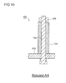
- Fig. 10 is a schematic diagram illustrating a conventional terminal connecting-and-fixing structure.
- a conventional terminal connecting-and-fixing structure 100 comprises a bus bar 110 having a plate-like shape, a bolt 130 penetrating the bus bar 110, and a terminal 120 mounted on the bolt 130. Further, the terminal 120 and the bus bar 110 is connected and fixed by fastening the nut 140 to the bolt 130, whereby the terminal 120 and the bus bar 110 are electrically continued.
- Patent Document 1 JP2005-16355 A
- the terminal 120 and the bolt 130 are composed of different materials and have different linear expansion coefficients.
- the fastening of the bolt 130 may be loosened due to the difference in the amount of thermal expansion between the two. Further, the fastening of the bolt 130 may also be loosened by e.g. vibration. If the fastening of the bolt 130 is loosened as above, the contact resistance between the terminal 120 and the bus bar 110 may be increased, and the conduction therebetween may become poor.
- the terminal connecting-and-fixing structure 100 is likely to be kept in a high-temperature environment. Further, as a forklift is started and stopped repeatedly in operation, vibration is likely to occur. Thus, there has been a problem such that poorness of conduction as described above is likely to arise.
- Patent document 1 discloses a stud bolt type terminal device having a structure where an O-ring is disposed at the boundary between a stud bolt and a resin mold cover in order to prevent entrance of foreign matters from an interspace resulting from a difference between the linear expansion coefficient of the stud bolt and the linear expansion coefficient of the resin mold cover.
- Patent Document 1 does not refer at all to preventing increase in the contact resistance due to the loose of the bolt.
- the present invention has been made in view of the above problems and is to provide a terminal connecting-and-fixing structure capable of ensuring the connection between the terminal and the bus bar even in the case of loose of the bolt and suppressing increase in the contact resistance, thereby preventing poorness of the conduction.
- the present invention has been made to accomplish an object as above and provides a terminal connecting-and-fixing structure comprising:
- the bus bar has a concave portion, and the terminal and the bus bar is connected and fixed by fastening the nut to the bolt while an end portion of the terminal is press-fitted in the concave portion. That is, the terminal and the bus bar is connected and fixed by press fitting, which provides a structure where the bus bar and the terminal are hard to be separated even if the bolt is loosened. Further, the terminal and the bus bar are in contact with each other not only at the end of the terminal and the bottom surface of the concave portion, but also at the outer peripheral surface of the terminal and the inner peripheral surface of the bus bar, whereby it is possible to ensure a large contact area relative to a conventional structure thereby to suppress the contact resistance.
- the terminal is made from a material having a linear expansion coefficient higher than a material of the bus bar.
- the end portion of the terminal and the concave portion have a pair of engagement means configured so that the end portion of the terminal is engaged with the concave portion by turning the terminal a prescribed degree around an axis of the bolt while the end portion of the terminal is press-fitted in the concave portion.
- the concave portion may have an opening end having a foldable collar portion projecting along a radial direction.
- a brazing material is disposed on an edge portion of the opening end of the concave portion.
- brazing material When a brazing material is disposed on an edge portion of the opening end of the concave portion as above, the brazing material will be melted in a high-temperature environment, whereby it is possible to ensure a large contact area between the terminal and the bus bar. Further, a gap which is possibly formed between the end portion and the concave portion of the bus bar can be filled with the brazing material, whereby it is possible to improve the waterproof property and the dust-proof property in the connecting-and-fixing portion.
- At least one of an inner peripheral surface or a bottom surface of the concave portion has a groove in which the brazing material being melted is to be flown because it is thereby possible to allow the molten brazing material to conductively flow between the end portion and the concave portion of the bus bar.
- the bolt is made from the same material as the material of the terminal.
- the terminal connecting-and-fixing structure according to the present invention may preferably be used for an inverter to be mounted on a battery-powered forklift.
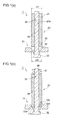
- Figs. 1(a) and (b) are schematic cross-sectional views illustrating a terminal connecting-and-fixing structure according to a first embodiment of the present invention.
- the terminal connecting-and-fixing structure 1 comprises a bus bar 10 having a plate-like shape, a bolt 30 penetrating the bus bar 10 and a nut 40 tightened by the bolt 30, and a terminal 20 mounted on the bolt 30.
- the bus bar 10 is a member made from cupper and having a plate-like shape and is a member through which an AC current converted from a DC current by an inverter (not shown) flows.
- the bus bar 10 has, as seen in Fig. 1(a) , a concave portion 12 thereon, which is depressed relative to its surrounding area in a concave shape.
- the shape of this concave portion 12 in a plan view is not particularly limited, and in this embodiment, it has a round shape having a diameter B.
- the terminal 20 is a member having, for example, a cylindrical shape made from brass, and it has an end portion 22 to be connected with the bus bar 10 to allow a flow therein of an AC current flowing through the bus bar 10.
- the terminal 20 has a central hole 20a, of which shape is not particularly limited but is, for example, a cylindrical shape having a slightly larger diameter A than the diameter B of the concave portion 12.
- the bolt 30 is, for example, a member made from iron and having a rod-like shape and has a spiral-shaped groove on a surface of its shaft portion 34.
- the shaft portion 34 is inserted into the central hole 20a of the terminal 20.
- a head portion 32 having a larger diameter than the shaft portion 34 is formed on the opposite side of the terminal 20 across the bus bar 10.
- the nut 40 is, for example, a ring-like member made from iron, which is screwable with the shaft portion 34 of the bolt 30.
- the end portion 22 and the concave portion 12 of the bus bar 10 are connected and fixed by fastening the nut 40 to the tip portion 36 of the bolt 30 while the end portion 22 of the terminal 20 is press-fitted in the concave portion 12 of the bus bar 10.
- the bus bar 10 and the terminal 20 are hard to be separated even when the bolt 30 is loosened as the terminal 20 and the bus bar 10 are connected and fixed by press fitting. Further, in the terminal connecting-and-fixing structure 1, the terminal 20 and the bus bar 10 are in contact with each other not only at the end 22b and the bottom surface 12b but also at the outer peripheral surface 22a and the inner peripheral surface 12a, whereby it is possible to ensure a large contact area, thereby to suppress the contact resistance.
- the material of the terminal 20 has a linear expansion coefficient larger than the bus bar 10. Accordingly, when the terminal connecting-and-fixing structure 1 is kept in a high-temperature environment and the terminal 20 and the bus bar 10 are thermally expanded, the press fit interference will not be decreased due to thermal expansion. Therefore, it is possible to connect and fix the terminal 20 and the bus bar 10 steadily even in a high-temperature environment.
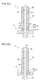
- Figs. 2(a) and (b) are schematic cross-sectional views illustrating a terminal connecting-and-fixing structure according to the second embodiment
- Fig. 3 and Fig. 4 are diagrams each illustrating a method of assembling the terminal connecting-and-fixing structure according to the second embodiment
- Figs. 3(a) to (c) are schematic perspective views illustrating the assembling method.
- Fig. 4(a) is a plan view of a bus bar 10
- Fig. 4(b) is a cross-sectional view along the line A-A in Fig. 3(b) and Fig. 4(a)
- Fig. 4(a) is a plan view of a bus bar
- FIG. 4(c) is a cross-sectional view along the line B-B in Fig. 4(a) .
- the terminal connecting-and-fixing structure according to the second embodiment fundamentally has the same structure as the above-described terminal connecting-and-fixing structure, and the same elements as those of the above embodiment are assigned with the same reference numerals as those of the above embodiment, and the same description thereof will be omitted.
- the end portion 22 of the terminal 20 has a terminal-side engagement means 25 comprising a concave part 25a and a convex part 25b, and the inner peripheral surface 12a of the concave portion 12 has a bus barside engagement means 25 comprising a convex part 15a.
- the terminal-side engagement means 25 and the bus bar-side engagement means 15 are configured so that they are engageable with each other. That is, the pair of engagement means 50 in the present invention comprises the terminal-side engagement means 25 and the bus bar-side engagement means 15.
- the concave part 25a of the terminal-side engagement means 25 is, as seen in Fig. 3(a) , formed all over the circumference of the outer surface of the end portion 22.
- the convex part 25b of the terminal-side engagement means 25 is formed not all over the circumference but partially in the circumferential direction. In this embodiment, the convex part 25b is formed in two positions 180 degrees apart from each other.
- the convex part 15a of the bus bar-side engagement means 15 is, as seen in Fig. 4(a) , formed not all over the circumference but partially along the circumferential edge of the concave portion 12. In the portion where the convex part 15a is not formed, an opening portion 15b is formed. In this embodiment, the opening portion 15b is formed in two positions 180 degrees apart from each other.
- the convex part 25b of the terminal 20 is inserted to fit into the opening portion 15b to press fit the end portion 22 of the terminal 20 into the concave portion 12.
- Fig. 3(b) and Fig. 4(b) illustrate such a condition.
- the convex part 25b of the terminal 20 is held between the convex part 15a and the bottom surface 12b of the concave portion 12, as seen in Fig. 3(c) and Fig. 4(c) , whereby the terminal-side engagement means 25 are engaged with the bus bar-side engagement means 15.
- the head portion of the bolt 30 is omitted for the convenience of drawing.
- the terminal connecting-and-fixing structure 1 has a pair of engagement means 50 configured so that the end portion 22 of the terminal 20 are engaged with the concave portion 12 by turning the terminal 20 a prescribed angle around an axis of the bolt 30 while the end portion 22 of the terminal 20 is press-fitted in the concave portion 12 of the concave portion 12.
- a pair of engagement means 50 configured so that the end portion 22 of the terminal 20 are engaged with the concave portion 12 by turning the terminal 20 a prescribed angle around an axis of the bolt 30 while the end portion 22 of the terminal 20 is press-fitted in the concave portion 12 of the concave portion 12.
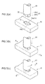
- Figs. 5(a) and (b) are schematic cross-sectional views illustrating the terminal connecting-and-fixing structure according to the third embodiment
- Figs. 6(a) and (b) are diagrams illustrating a bus bar according to the third embodiment.
- the terminal connecting-and-fixing structure according to the this embodiment fundamentally has the same structure as the terminal connecting-and-fixing structure according to the first embodiment, and the same elements as those of the first embodiment are assigned with the same reference numerals as those of the first embodiment, and the same description thereof will be omitted.
- the terminal connecting-and-fixing structure 1 is different from the first embodiment in that the concave portion 12 has an opening end having a foldable collar portion 17, as illustrated in Figs. 5(a) and (b) .
- the collar portion 17 is formed so as to project along a radial direction in the opening end portion of the concave portion 12, as illustrated in Fig. 6(b) .
- the color portion 17 is foldable because of a plurality of cuts 17a formed at the portion projecting along the radial direction.
- terminal connecting-and-fixing structure 1 is obtained by folding the collar portion 17 upward as indicated by the arrows in Fig. 6(b) , and then press fitting the end portion 22 of the terminal 20 into the concave portion 12.
- the concave portion 12 has an opening end having a foldable collar portion 17 projecting along a radial direction, whereby it is possible to ensure the connection at least between the collar portion 17 and the outer peripheral surface 22a of the end portion 22 of the terminal 20 even when the bolt 30 is loosened and moved in the axial direction.
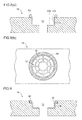
- Figs. 7(a) and (b) are schematic cross-sectional views illustrating a terminal connecting-and-fixing structure according to a fourth embodiment
- Fig. 8 and Fig. 9 are each a schematic diagram of a variation of the terminal connecting-and-fixing structure of the fourth embodiment.
- the terminal connecting-and-fixing structure according to the this embodiment fundamentally has the same structure as the terminal connecting-and-fixing structure according to the first embodiment, and the same elements as those of the first embodiment are assigned with the same reference numerals as those of the first embodiment, and the same description thereof will be omitted.
- the terminal connecting-and-fixing structure 1 is different from the first embodiment in that a brazing material 60 is disposed on an edge portion of the opening end of the concave portion 12, as illustrated in Figs. 7(a) and (b) .
- the brazing material 60 may, for example, be a ring-like member made from e.g. silver, copper or phosphor copper, and will be melted when the terminal connecting-and-fixing structure 1 is kept in a high-temperature environment.
- the molten brazing material 60 will flow into a tiny gap formed between the end portion 22 of the terminal 20 and the concave portion 12 of the bus bar 10, whereby the terminal 20 and the bus bar 10 are connected without a gap.
- the terminal connecting-and-fixing structure 1 comprises a brazing material 60 disposed on an edge portion of the opening end of the concave portion 12, and the brazing material 60 will be melted to fill a gap formed between the end portion 22 of the terminal 20 and the concave portion 12 of the bus bar 10, whereby it is possible to ensure a large contact area between the terminal 20 and the bus bar 10. Further, a gap which is possibly formed between the end portion 11 of the terminal 20 and the concave portion 12 of the bus bar 10 can be filled with the brazing material, whereby it is possible to improve the waterproof property and the dust-proof property in the connecting-and-fixing portion.
- the inner peripheral surface 12a and the bottom surface 12b of the concave portion 12 has a groove 14 because it is thereby possible to allow the molten brazing material 60 to conductively flow between the end portion 22 of the terminal 20 and the concave portion 12 of the bus bar 10, as illustrated in Figs. 8(a) and (b) . Further, although not shown in the figure, it may be that only at least one of the inner peripheral surface 12a or the bottom surface 12b of the concave portion 12 has such a groove 14.
- the edge portion of the opening end of the concave portion 12 may have a step portion 16 having a height lower than the surface of the bus bar 10 by a step, as illustrated in Fig. 9 .
- a step portion 16 it is possible to dispose the brazing material 60 on the step portion 16, thereby to facilitate positioning of the brazing material 60 to be disposed. Further, it is also possible to prevent outflow of the molten brazing material 60 to the surface of the bus bar 10.
- the terminal connecting-and-fixing structure 1 is not limited thereto, and the bolt 30 may be made from the same material (e.g. brass) as the material of the terminal.
- the bolt 30 is made from the same material as the material of the terminal 20 as above, they have the same linear expansion, and the thermal expansion amount will also be the same, whereby it is possible to suppress loose of the bolt 30 itself arising from the difference in the thermal expansion coefficient between the bolt 30 and the terminal 20.
- the present invention can be used as, for example, a terminal connecting-and-fixing structure for and inverter, preferably as a terminal connecting-and-fixing structure for an inverter to be kept in a high-temperature environment, such as an inverter to be mounted on a battery-powered forklift.
Applications Claiming Priority (2)
| Application Number | Priority Date | Filing Date | Title |
|---|---|---|---|
| JP2012022160A JP2013161627A (ja) | 2012-02-03 | 2012-02-03 | ターミナル接続固定構造 |
| PCT/JP2012/076804 WO2013114687A1 (ja) | 2012-02-03 | 2012-10-17 | ターミナル接続固定構造 |
Publications (3)
| Publication Number | Publication Date |
|---|---|
| EP2811576A1 true EP2811576A1 (de) | 2014-12-10 |
| EP2811576A4 EP2811576A4 (de) | 2015-09-30 |
| EP2811576B1 EP2811576B1 (de) | 2018-12-12 |
Family
ID=48904753
Family Applications (1)
| Application Number | Title | Priority Date | Filing Date |
|---|---|---|---|
| EP12867222.7A Active EP2811576B1 (de) | 2012-02-03 | 2012-10-17 | Endgerät zur sicherung einer verbindungsstruktur |
Country Status (4)
| Country | Link |
|---|---|
| US (1) | US9225080B2 (de) |
| EP (1) | EP2811576B1 (de) |
| JP (1) | JP2013161627A (de) |
| WO (1) | WO2013114687A1 (de) |
Cited By (3)
| Publication number | Priority date | Publication date | Assignee | Title |
|---|---|---|---|---|
| FR3037193A1 (fr) * | 2015-06-04 | 2016-12-09 | Auxel | Distributeur de courant a bornes |
| WO2017081245A1 (fr) * | 2015-11-13 | 2017-05-18 | Valeo Systemes De Controle Moteur | Barre de connexion electrique |
| CN107706619A (zh) * | 2017-10-27 | 2018-02-16 | 镇江科胜电子科技有限公司 | 一种快连式电子连接器 |
Families Citing this family (8)
| Publication number | Priority date | Publication date | Assignee | Title |
|---|---|---|---|---|
| JP6323902B2 (ja) * | 2014-03-05 | 2018-05-16 | 矢崎総業株式会社 | 電気接続箱 |
| US11211754B2 (en) * | 2016-05-24 | 2021-12-28 | Gong Zhu | Switch device |
| KR101756716B1 (ko) * | 2016-07-18 | 2017-07-11 | 사단법인 장우 일자리협회 | 볼트 풀림 방지기능을 갖춘 단자대 블록 |
| KR101756729B1 (ko) * | 2016-07-18 | 2017-07-11 | 사단법인 장우 일자리협회 | 케이블 단자대용 풀림방지너트 |
| DE102020134255A1 (de) * | 2020-12-18 | 2022-06-23 | Te Connectivity Germany Gmbh | Sammelschienenkontakt zur Anbringung an einer Sammelschiene, und Verfahren zur Anbringung eines Sammelschienenkontakts |
| CN113054461B (zh) * | 2021-03-23 | 2022-11-11 | 东莞市旭电电子科技有限公司 | 一种使用寿命长的插头用磷铜管 |
| JP7224389B2 (ja) * | 2021-04-27 | 2023-02-17 | 三菱電機株式会社 | ターミナル接続構造 |
| US11616311B1 (en) * | 2022-01-11 | 2023-03-28 | Drow Enterprise Co., Ltd. | Electrical connector fastener assembly |
Family Cites Families (12)
| Publication number | Priority date | Publication date | Assignee | Title |
|---|---|---|---|---|
| GB221914A (en) | 1923-07-20 | 1924-09-25 | John Skerrett Adrian Walsh | Improvements in terminals or connections for electric conductors |
| JPS5063494A (de) | 1973-10-08 | 1975-05-29 | ||
| US5579217A (en) | 1991-07-10 | 1996-11-26 | Kenetech Windpower, Inc. | Laminated bus assembly and coupling apparatus for a high power electrical switching converter |
| US6347966B1 (en) * | 2000-05-31 | 2002-02-19 | Homac Manufacturing Company | Method for making bus and post electrical connector using displaced bus material and connector produced thereby |
| JP2005016355A (ja) | 2003-06-24 | 2005-01-20 | Denso Corp | スタッドボルト式ターミナル装置 |
| JP4191689B2 (ja) | 2005-02-25 | 2008-12-03 | 三菱重工業株式会社 | インバータ装置 |
| US7344421B1 (en) | 2005-06-06 | 2008-03-18 | Spencer Troy L | Quick release battery cable connector |
| JP2007124751A (ja) | 2005-10-26 | 2007-05-17 | Toyota Motor Corp | バスバー接続部 |
| JP3120249U (ja) | 2005-11-28 | 2006-03-30 | 有限会社テクニカル・ビジョン | 金属箔ヒーター用リード線端子 |
| JP2009181944A (ja) | 2008-02-01 | 2009-08-13 | Yazaki Corp | フランジの固定構造 |
| US20120227389A1 (en) | 2008-04-16 | 2012-09-13 | Hinderks M V | Reciprocating machine & other devices |
| US8466586B2 (en) * | 2008-10-03 | 2013-06-18 | GM Global Technology Operations LLC | High-voltage terminal assembly with integral high-voltage interlock |
-
2012
- 2012-02-03 JP JP2012022160A patent/JP2013161627A/ja active Pending
- 2012-10-17 US US14/371,469 patent/US9225080B2/en active Active
- 2012-10-17 WO PCT/JP2012/076804 patent/WO2013114687A1/ja active Application Filing
- 2012-10-17 EP EP12867222.7A patent/EP2811576B1/de active Active
Cited By (5)
| Publication number | Priority date | Publication date | Assignee | Title |
|---|---|---|---|---|
| FR3037193A1 (fr) * | 2015-06-04 | 2016-12-09 | Auxel | Distributeur de courant a bornes |
| WO2017081245A1 (fr) * | 2015-11-13 | 2017-05-18 | Valeo Systemes De Controle Moteur | Barre de connexion electrique |
| FR3043851A1 (fr) * | 2015-11-13 | 2017-05-19 | Valeo Systemes De Controle Moteur | Barre de connexion electrique |
| US10953825B2 (en) | 2015-11-13 | 2021-03-23 | Valeo Siemens Eautomotive France Sas | Electrical busbar |
| CN107706619A (zh) * | 2017-10-27 | 2018-02-16 | 镇江科胜电子科技有限公司 | 一种快连式电子连接器 |
Also Published As
| Publication number | Publication date |
|---|---|
| US20140349527A1 (en) | 2014-11-27 |
| EP2811576A4 (de) | 2015-09-30 |
| US9225080B2 (en) | 2015-12-29 |
| EP2811576B1 (de) | 2018-12-12 |
| JP2013161627A (ja) | 2013-08-19 |
| WO2013114687A1 (ja) | 2013-08-08 |
Similar Documents
| Publication | Publication Date | Title |
|---|---|---|
| US9225080B2 (en) | Terminal connecting-and-fixing structure | |
| US11277047B2 (en) | Busbar apparatus, motor, and method of manufacturing busbar apparatus | |
| US20220183140A1 (en) | Metal member-equipped circuit board, circuit assembly, and electrical junction box | |
| JP5606581B1 (ja) | 車両用電源装置 | |
| US8414321B2 (en) | Power element for a motor of an industrial truck | |
| EP2947438A1 (de) | Elektromotor | |
| US10855138B2 (en) | Electrical machine and method for producing an electrical machine | |
| US20150288241A1 (en) | Stator pressed with winding head support | |
| US7485815B2 (en) | Mounting device for a capacitor | |
| CN108781019B (zh) | 电机和用于制造电机的方法 | |
| EP3021461A2 (de) | Elektrischer Motor | |
| US10950844B2 (en) | Battery pole and electrical contact unit for producing an electrical connection between a battery pole and an on-board electrical system of a vehicle | |
| WO2013190969A1 (ja) | 締結構造 | |
| US20140022729A1 (en) | Voltage regulator for an alternator | |
| WO2014181741A1 (ja) | 端子化電線 | |
| JP5215152B2 (ja) | 電気接続箱 | |
| US20100212955A1 (en) | Electrical apparatus | |
| JP6444928B2 (ja) | 電動機の防水構造 | |
| CN107079597B (zh) | 用于容纳电气和/或电子部件的壳体、电子控制装置及制造该壳体和电子控制装置的方法 | |
| JP5129658B2 (ja) | 端子防水構造を備えたスタータモータ | |
| JP5595537B2 (ja) | 電動パワーステアリング装置 | |
| KR20170042641A (ko) | 전기 장치 | |
| EP2615895B1 (de) | Sammelschiene und elektronische Vorrichtung | |
| US20150229188A1 (en) | Ground wire connection structure for motor | |
| JP5154847B2 (ja) | オイルチェックセンサ |
Legal Events
| Date | Code | Title | Description |
|---|---|---|---|
| PUAI | Public reference made under article 153(3) epc to a published international application that has entered the european phase |
Free format text: ORIGINAL CODE: 0009012 |
|
| 17P | Request for examination filed |
Effective date: 20140625 |
|
| AK | Designated contracting states |
Kind code of ref document: A1 Designated state(s): AL AT BE BG CH CY CZ DE DK EE ES FI FR GB GR HR HU IE IS IT LI LT LU LV MC MK MT NL NO PL PT RO RS SE SI SK SM TR |
|
| AX | Request for extension of the european patent |
Extension state: BA ME |
|
| DAX | Request for extension of the european patent (deleted) | ||
| RA4 | Supplementary search report drawn up and despatched (corrected) |
Effective date: 20150831 |
|
| RIC1 | Information provided on ipc code assigned before grant |
Ipc: F02M 51/06 20060101ALI20150825BHEP Ipc: H01R 4/00 20060101ALI20150825BHEP Ipc: H01R 4/18 20060101ALI20150825BHEP Ipc: H01R 43/16 20060101ALI20150825BHEP Ipc: H01R 4/30 20060101AFI20150825BHEP Ipc: H01R 25/16 20060101ALI20150825BHEP Ipc: H01R 4/02 20060101ALI20150825BHEP Ipc: H02M 7/00 20060101ALI20150825BHEP |
|
| GRAP | Despatch of communication of intention to grant a patent |
Free format text: ORIGINAL CODE: EPIDOSNIGR1 |
|
| STAA | Information on the status of an ep patent application or granted ep patent |
Free format text: STATUS: GRANT OF PATENT IS INTENDED |
|
| INTG | Intention to grant announced |
Effective date: 20180503 |
|
| GRAS | Grant fee paid |
Free format text: ORIGINAL CODE: EPIDOSNIGR3 |
|
| RAP1 | Party data changed (applicant data changed or rights of an application transferred) |
Owner name: MITSUBISHI LOGISNEXT CO., LTD. |
|
| GRAA | (expected) grant |
Free format text: ORIGINAL CODE: 0009210 |
|
| STAA | Information on the status of an ep patent application or granted ep patent |
Free format text: STATUS: THE PATENT HAS BEEN GRANTED |
|
| AK | Designated contracting states |
Kind code of ref document: B1 Designated state(s): AL AT BE BG CH CY CZ DE DK EE ES FI FR GB GR HR HU IE IS IT LI LT LU LV MC MK MT NL NO PL PT RO RS SE SI SK SM TR |
|
| REG | Reference to a national code |
Ref country code: GB Ref legal event code: FG4D |
|
| REG | Reference to a national code |
Ref country code: CH Ref legal event code: EP |
|
| REG | Reference to a national code |
Ref country code: AT Ref legal event code: REF Ref document number: 1077210 Country of ref document: AT Kind code of ref document: T Effective date: 20181215 |
|
| REG | Reference to a national code |
Ref country code: DE Ref legal event code: R096 Ref document number: 602012054722 Country of ref document: DE |
|
| REG | Reference to a national code |
Ref country code: IE Ref legal event code: FG4D |
|
| REG | Reference to a national code |
Ref country code: NL Ref legal event code: MP Effective date: 20181212 |
|
| REG | Reference to a national code |
Ref country code: LT Ref legal event code: MG4D |
|
| PG25 | Lapsed in a contracting state [announced via postgrant information from national office to epo] |
Ref country code: LT Free format text: LAPSE BECAUSE OF FAILURE TO SUBMIT A TRANSLATION OF THE DESCRIPTION OR TO PAY THE FEE WITHIN THE PRESCRIBED TIME-LIMIT Effective date: 20181212 Ref country code: ES Free format text: LAPSE BECAUSE OF FAILURE TO SUBMIT A TRANSLATION OF THE DESCRIPTION OR TO PAY THE FEE WITHIN THE PRESCRIBED TIME-LIMIT Effective date: 20181212 Ref country code: NO Free format text: LAPSE BECAUSE OF FAILURE TO SUBMIT A TRANSLATION OF THE DESCRIPTION OR TO PAY THE FEE WITHIN THE PRESCRIBED TIME-LIMIT Effective date: 20190312 Ref country code: BG Free format text: LAPSE BECAUSE OF FAILURE TO SUBMIT A TRANSLATION OF THE DESCRIPTION OR TO PAY THE FEE WITHIN THE PRESCRIBED TIME-LIMIT Effective date: 20190312 Ref country code: HR Free format text: LAPSE BECAUSE OF FAILURE TO SUBMIT A TRANSLATION OF THE DESCRIPTION OR TO PAY THE FEE WITHIN THE PRESCRIBED TIME-LIMIT Effective date: 20181212 Ref country code: LV Free format text: LAPSE BECAUSE OF FAILURE TO SUBMIT A TRANSLATION OF THE DESCRIPTION OR TO PAY THE FEE WITHIN THE PRESCRIBED TIME-LIMIT Effective date: 20181212 Ref country code: FI Free format text: LAPSE BECAUSE OF FAILURE TO SUBMIT A TRANSLATION OF THE DESCRIPTION OR TO PAY THE FEE WITHIN THE PRESCRIBED TIME-LIMIT Effective date: 20181212 |
|
| REG | Reference to a national code |
Ref country code: AT Ref legal event code: MK05 Ref document number: 1077210 Country of ref document: AT Kind code of ref document: T Effective date: 20181212 |
|
| PG25 | Lapsed in a contracting state [announced via postgrant information from national office to epo] |
Ref country code: SE Free format text: LAPSE BECAUSE OF FAILURE TO SUBMIT A TRANSLATION OF THE DESCRIPTION OR TO PAY THE FEE WITHIN THE PRESCRIBED TIME-LIMIT Effective date: 20181212 Ref country code: AL Free format text: LAPSE BECAUSE OF FAILURE TO SUBMIT A TRANSLATION OF THE DESCRIPTION OR TO PAY THE FEE WITHIN THE PRESCRIBED TIME-LIMIT Effective date: 20181212 Ref country code: RS Free format text: LAPSE BECAUSE OF FAILURE TO SUBMIT A TRANSLATION OF THE DESCRIPTION OR TO PAY THE FEE WITHIN THE PRESCRIBED TIME-LIMIT Effective date: 20181212 Ref country code: GR Free format text: LAPSE BECAUSE OF FAILURE TO SUBMIT A TRANSLATION OF THE DESCRIPTION OR TO PAY THE FEE WITHIN THE PRESCRIBED TIME-LIMIT Effective date: 20190313 |
|
| PG25 | Lapsed in a contracting state [announced via postgrant information from national office to epo] |
Ref country code: NL Free format text: LAPSE BECAUSE OF FAILURE TO SUBMIT A TRANSLATION OF THE DESCRIPTION OR TO PAY THE FEE WITHIN THE PRESCRIBED TIME-LIMIT Effective date: 20181212 |
|
| PG25 | Lapsed in a contracting state [announced via postgrant information from national office to epo] |
Ref country code: PT Free format text: LAPSE BECAUSE OF FAILURE TO SUBMIT A TRANSLATION OF THE DESCRIPTION OR TO PAY THE FEE WITHIN THE PRESCRIBED TIME-LIMIT Effective date: 20190412 Ref country code: PL Free format text: LAPSE BECAUSE OF FAILURE TO SUBMIT A TRANSLATION OF THE DESCRIPTION OR TO PAY THE FEE WITHIN THE PRESCRIBED TIME-LIMIT Effective date: 20181212 Ref country code: CZ Free format text: LAPSE BECAUSE OF FAILURE TO SUBMIT A TRANSLATION OF THE DESCRIPTION OR TO PAY THE FEE WITHIN THE PRESCRIBED TIME-LIMIT Effective date: 20181212 |
|
| PG25 | Lapsed in a contracting state [announced via postgrant information from national office to epo] |
Ref country code: IS Free format text: LAPSE BECAUSE OF FAILURE TO SUBMIT A TRANSLATION OF THE DESCRIPTION OR TO PAY THE FEE WITHIN THE PRESCRIBED TIME-LIMIT Effective date: 20190412 Ref country code: SM Free format text: LAPSE BECAUSE OF FAILURE TO SUBMIT A TRANSLATION OF THE DESCRIPTION OR TO PAY THE FEE WITHIN THE PRESCRIBED TIME-LIMIT Effective date: 20181212 Ref country code: RO Free format text: LAPSE BECAUSE OF FAILURE TO SUBMIT A TRANSLATION OF THE DESCRIPTION OR TO PAY THE FEE WITHIN THE PRESCRIBED TIME-LIMIT Effective date: 20181212 Ref country code: SK Free format text: LAPSE BECAUSE OF FAILURE TO SUBMIT A TRANSLATION OF THE DESCRIPTION OR TO PAY THE FEE WITHIN THE PRESCRIBED TIME-LIMIT Effective date: 20181212 Ref country code: EE Free format text: LAPSE BECAUSE OF FAILURE TO SUBMIT A TRANSLATION OF THE DESCRIPTION OR TO PAY THE FEE WITHIN THE PRESCRIBED TIME-LIMIT Effective date: 20181212 |
|
| REG | Reference to a national code |
Ref country code: DE Ref legal event code: R097 Ref document number: 602012054722 Country of ref document: DE |
|
| PLBE | No opposition filed within time limit |
Free format text: ORIGINAL CODE: 0009261 |
|
| STAA | Information on the status of an ep patent application or granted ep patent |
Free format text: STATUS: NO OPPOSITION FILED WITHIN TIME LIMIT |
|
| PG25 | Lapsed in a contracting state [announced via postgrant information from national office to epo] |
Ref country code: SI Free format text: LAPSE BECAUSE OF FAILURE TO SUBMIT A TRANSLATION OF THE DESCRIPTION OR TO PAY THE FEE WITHIN THE PRESCRIBED TIME-LIMIT Effective date: 20181212 Ref country code: AT Free format text: LAPSE BECAUSE OF FAILURE TO SUBMIT A TRANSLATION OF THE DESCRIPTION OR TO PAY THE FEE WITHIN THE PRESCRIBED TIME-LIMIT Effective date: 20181212 Ref country code: DK Free format text: LAPSE BECAUSE OF FAILURE TO SUBMIT A TRANSLATION OF THE DESCRIPTION OR TO PAY THE FEE WITHIN THE PRESCRIBED TIME-LIMIT Effective date: 20181212 |
|
| 26N | No opposition filed |
Effective date: 20190913 |
|
| PG25 | Lapsed in a contracting state [announced via postgrant information from national office to epo] |
Ref country code: TR Free format text: LAPSE BECAUSE OF FAILURE TO SUBMIT A TRANSLATION OF THE DESCRIPTION OR TO PAY THE FEE WITHIN THE PRESCRIBED TIME-LIMIT Effective date: 20181212 |
|
| PG25 | Lapsed in a contracting state [announced via postgrant information from national office to epo] |
Ref country code: MC Free format text: LAPSE BECAUSE OF FAILURE TO SUBMIT A TRANSLATION OF THE DESCRIPTION OR TO PAY THE FEE WITHIN THE PRESCRIBED TIME-LIMIT Effective date: 20181212 |
|
| REG | Reference to a national code |
Ref country code: CH Ref legal event code: PL |
|
| PG25 | Lapsed in a contracting state [announced via postgrant information from national office to epo] |
Ref country code: LI Free format text: LAPSE BECAUSE OF NON-PAYMENT OF DUE FEES Effective date: 20191031 Ref country code: CH Free format text: LAPSE BECAUSE OF NON-PAYMENT OF DUE FEES Effective date: 20191031 Ref country code: LU Free format text: LAPSE BECAUSE OF NON-PAYMENT OF DUE FEES Effective date: 20191017 |
|
| REG | Reference to a national code |
Ref country code: BE Ref legal event code: MM Effective date: 20191031 |
|
| PG25 | Lapsed in a contracting state [announced via postgrant information from national office to epo] |
Ref country code: BE Free format text: LAPSE BECAUSE OF NON-PAYMENT OF DUE FEES Effective date: 20191031 |
|
| PG25 | Lapsed in a contracting state [announced via postgrant information from national office to epo] |
Ref country code: IE Free format text: LAPSE BECAUSE OF NON-PAYMENT OF DUE FEES Effective date: 20191017 |
|
| PG25 | Lapsed in a contracting state [announced via postgrant information from national office to epo] |
Ref country code: CY Free format text: LAPSE BECAUSE OF FAILURE TO SUBMIT A TRANSLATION OF THE DESCRIPTION OR TO PAY THE FEE WITHIN THE PRESCRIBED TIME-LIMIT Effective date: 20181212 |
|
| PG25 | Lapsed in a contracting state [announced via postgrant information from national office to epo] |
Ref country code: HU Free format text: LAPSE BECAUSE OF FAILURE TO SUBMIT A TRANSLATION OF THE DESCRIPTION OR TO PAY THE FEE WITHIN THE PRESCRIBED TIME-LIMIT; INVALID AB INITIO Effective date: 20121017 Ref country code: MT Free format text: LAPSE BECAUSE OF FAILURE TO SUBMIT A TRANSLATION OF THE DESCRIPTION OR TO PAY THE FEE WITHIN THE PRESCRIBED TIME-LIMIT Effective date: 20181212 |
|
| PG25 | Lapsed in a contracting state [announced via postgrant information from national office to epo] |
Ref country code: MK Free format text: LAPSE BECAUSE OF FAILURE TO SUBMIT A TRANSLATION OF THE DESCRIPTION OR TO PAY THE FEE WITHIN THE PRESCRIBED TIME-LIMIT Effective date: 20181212 |
|
| P01 | Opt-out of the competence of the unified patent court (upc) registered |
Effective date: 20230509 |
|
| PGFP | Annual fee paid to national office [announced via postgrant information from national office to epo] |
Ref country code: IT Payment date: 20230913 Year of fee payment: 12 Ref country code: GB Payment date: 20230831 Year of fee payment: 12 |
|
| PGFP | Annual fee paid to national office [announced via postgrant information from national office to epo] |
Ref country code: FR Payment date: 20230911 Year of fee payment: 12 |
|
| PGFP | Annual fee paid to national office [announced via postgrant information from national office to epo] |
Ref country code: DE Payment date: 20230830 Year of fee payment: 12 |