EP2811301B1 - Qualitäts-/Prozesssteuerung einer Lateralflusstestvorrichtung auf Grundlage von Flussüberwachung - Google Patents
Qualitäts-/Prozesssteuerung einer Lateralflusstestvorrichtung auf Grundlage von Flussüberwachung Download PDFInfo
- Publication number
- EP2811301B1 EP2811301B1 EP13192854.1A EP13192854A EP2811301B1 EP 2811301 B1 EP2811301 B1 EP 2811301B1 EP 13192854 A EP13192854 A EP 13192854A EP 2811301 B1 EP2811301 B1 EP 2811301B1
- Authority
- EP
- European Patent Office
- Prior art keywords
- zone
- sample
- detection
- recited
- reagent
- Prior art date
- Legal status (The legal status is an assumption and is not a legal conclusion. Google has not performed a legal analysis and makes no representation as to the accuracy of the status listed.)
- Active
Links
- 238000003556 assay Methods 0.000 title claims description 180
- 238000012544 monitoring process Methods 0.000 title claims description 34
- 238000003908 quality control method Methods 0.000 title claims description 8
- 238000004886 process control Methods 0.000 title description 2
- 238000001514 detection method Methods 0.000 claims description 278
- 239000003153 chemical reaction reagent Substances 0.000 claims description 148
- 238000000034 method Methods 0.000 claims description 130
- 239000000463 material Substances 0.000 claims description 98
- 239000012530 fluid Substances 0.000 claims description 80
- 238000012360 testing method Methods 0.000 claims description 64
- 239000000758 substrate Substances 0.000 claims description 38
- 239000012491 analyte Substances 0.000 claims description 29
- 238000005259 measurement Methods 0.000 claims description 16
- 230000009471 action Effects 0.000 claims description 12
- 230000000977 initiatory effect Effects 0.000 claims 2
- 239000000523 sample Substances 0.000 description 228
- 238000006243 chemical reaction Methods 0.000 description 21
- 239000007788 liquid Substances 0.000 description 21
- 230000008569 process Effects 0.000 description 20
- 238000013461 design Methods 0.000 description 15
- 230000027455 binding Effects 0.000 description 12
- 239000011148 porous material Substances 0.000 description 10
- 238000004891 communication Methods 0.000 description 9
- 238000004090 dissolution Methods 0.000 description 9
- -1 e.g. Substances 0.000 description 9
- 210000004369 blood Anatomy 0.000 description 8
- 239000008280 blood Substances 0.000 description 8
- 239000004033 plastic Substances 0.000 description 8
- 229920003023 plastic Polymers 0.000 description 8
- 230000007547 defect Effects 0.000 description 7
- 239000003814 drug Substances 0.000 description 7
- 102000004169 proteins and genes Human genes 0.000 description 7
- 108090000623 proteins and genes Proteins 0.000 description 7
- 210000001519 tissue Anatomy 0.000 description 7
- 239000000020 Nitrocellulose Substances 0.000 description 6
- FJWGYAHXMCUOOM-QHOUIDNNSA-N [(2s,3r,4s,5r,6r)-2-[(2r,3r,4s,5r,6s)-4,5-dinitrooxy-2-(nitrooxymethyl)-6-[(2r,3r,4s,5r,6s)-4,5,6-trinitrooxy-2-(nitrooxymethyl)oxan-3-yl]oxyoxan-3-yl]oxy-3,5-dinitrooxy-6-(nitrooxymethyl)oxan-4-yl] nitrate Chemical compound O([C@@H]1O[C@@H]([C@H]([C@H](O[N+]([O-])=O)[C@H]1O[N+]([O-])=O)O[C@H]1[C@@H]([C@@H](O[N+]([O-])=O)[C@H](O[N+]([O-])=O)[C@@H](CO[N+]([O-])=O)O1)O[N+]([O-])=O)CO[N+](=O)[O-])[C@@H]1[C@@H](CO[N+]([O-])=O)O[C@@H](O[N+]([O-])=O)[C@H](O[N+]([O-])=O)[C@H]1O[N+]([O-])=O FJWGYAHXMCUOOM-QHOUIDNNSA-N 0.000 description 6
- 229920001220 nitrocellulos Polymers 0.000 description 6
- 229940079593 drug Drugs 0.000 description 5
- 238000000605 extraction Methods 0.000 description 5
- 239000011888 foil Substances 0.000 description 5
- 210000002381 plasma Anatomy 0.000 description 5
- 238000012545 processing Methods 0.000 description 5
- 230000002285 radioactive effect Effects 0.000 description 5
- 210000002700 urine Anatomy 0.000 description 5
- 239000004793 Polystyrene Substances 0.000 description 4
- 239000000427 antigen Substances 0.000 description 4
- 108091007433 antigens Proteins 0.000 description 4
- 102000036639 antigens Human genes 0.000 description 4
- 230000008901 benefit Effects 0.000 description 4
- 239000003795 chemical substances by application Substances 0.000 description 4
- 230000008021 deposition Effects 0.000 description 4
- 239000004816 latex Substances 0.000 description 4
- 229920000126 latex Polymers 0.000 description 4
- 238000004519 manufacturing process Methods 0.000 description 4
- 229920000058 polyacrylate Polymers 0.000 description 4
- 229920000642 polymer Polymers 0.000 description 4
- 229920002223 polystyrene Polymers 0.000 description 4
- 206010036790 Productive cough Diseases 0.000 description 3
- 210000004027 cell Anatomy 0.000 description 3
- 229920001577 copolymer Polymers 0.000 description 3
- 230000003111 delayed effect Effects 0.000 description 3
- 208000037265 diseases, disorders, signs and symptoms Diseases 0.000 description 3
- 239000007850 fluorescent dye Substances 0.000 description 3
- 238000011065 in-situ storage Methods 0.000 description 3
- 238000002347 injection Methods 0.000 description 3
- 239000007924 injection Substances 0.000 description 3
- 238000009434 installation Methods 0.000 description 3
- 239000003550 marker Substances 0.000 description 3
- 239000002184 metal Substances 0.000 description 3
- 229910052751 metal Inorganic materials 0.000 description 3
- 239000000203 mixture Substances 0.000 description 3
- 238000012986 modification Methods 0.000 description 3
- 230000004048 modification Effects 0.000 description 3
- 150000007523 nucleic acids Chemical class 0.000 description 3
- 230000003287 optical effect Effects 0.000 description 3
- 229920000515 polycarbonate Polymers 0.000 description 3
- 239000004417 polycarbonate Substances 0.000 description 3
- 210000003802 sputum Anatomy 0.000 description 3
- 208000024794 sputum Diseases 0.000 description 3
- 239000000126 substance Substances 0.000 description 3
- 239000006226 wash reagent Substances 0.000 description 3
- YBJHBAHKTGYVGT-ZKWXMUAHSA-N (+)-Biotin Chemical group N1C(=O)N[C@@H]2[C@H](CCCCC(=O)O)SC[C@@H]21 YBJHBAHKTGYVGT-ZKWXMUAHSA-N 0.000 description 2
- 241000894006 Bacteria Species 0.000 description 2
- 108090000790 Enzymes Proteins 0.000 description 2
- 102000004190 Enzymes Human genes 0.000 description 2
- WQZGKKKJIJFFOK-GASJEMHNSA-N Glucose Natural products OC[C@H]1OC(O)[C@H](O)[C@@H](O)[C@@H]1O WQZGKKKJIJFFOK-GASJEMHNSA-N 0.000 description 2
- 241001465754 Metazoa Species 0.000 description 2
- 239000004698 Polyethylene Substances 0.000 description 2
- 239000004743 Polypropylene Substances 0.000 description 2
- PPBRXRYQALVLMV-UHFFFAOYSA-N Styrene Chemical compound C=CC1=CC=CC=C1 PPBRXRYQALVLMV-UHFFFAOYSA-N 0.000 description 2
- 102000011923 Thyrotropin Human genes 0.000 description 2
- 108010061174 Thyrotropin Proteins 0.000 description 2
- 238000004458 analytical method Methods 0.000 description 2
- 238000013459 approach Methods 0.000 description 2
- 230000009286 beneficial effect Effects 0.000 description 2
- 210000000601 blood cell Anatomy 0.000 description 2
- HVYWMOMLDIMFJA-DPAQBDIFSA-N cholesterol Chemical compound C1C=C2C[C@@H](O)CC[C@]2(C)[C@@H]2[C@@H]1[C@@H]1CC[C@H]([C@H](C)CCCC(C)C)[C@@]1(C)CC2 HVYWMOMLDIMFJA-DPAQBDIFSA-N 0.000 description 2
- 239000011248 coating agent Substances 0.000 description 2
- 238000000576 coating method Methods 0.000 description 2
- 238000012937 correction Methods 0.000 description 2
- 230000001934 delay Effects 0.000 description 2
- 201000010099 disease Diseases 0.000 description 2
- 239000002359 drug metabolite Substances 0.000 description 2
- 229920001971 elastomer Polymers 0.000 description 2
- 239000000806 elastomer Substances 0.000 description 2
- 239000008103 glucose Substances 0.000 description 2
- 229920001600 hydrophobic polymer Polymers 0.000 description 2
- 238000010191 image analysis Methods 0.000 description 2
- 238000003384 imaging method Methods 0.000 description 2
- 238000003018 immunoassay Methods 0.000 description 2
- 238000001746 injection moulding Methods 0.000 description 2
- 230000003993 interaction Effects 0.000 description 2
- 230000002452 interceptive effect Effects 0.000 description 2
- 238000011068 loading method Methods 0.000 description 2
- 239000011104 metalized film Substances 0.000 description 2
- 150000002739 metals Chemical class 0.000 description 2
- 102000039446 nucleic acids Human genes 0.000 description 2
- 108020004707 nucleic acids Proteins 0.000 description 2
- 229920000728 polyester Polymers 0.000 description 2
- 229920000573 polyethylene Polymers 0.000 description 2
- 229920001155 polypropylene Polymers 0.000 description 2
- 230000002028 premature Effects 0.000 description 2
- 239000000376 reactant Substances 0.000 description 2
- 210000003296 saliva Anatomy 0.000 description 2
- 210000002966 serum Anatomy 0.000 description 2
- 239000000243 solution Substances 0.000 description 2
- 230000009870 specific binding Effects 0.000 description 2
- 239000000725 suspension Substances 0.000 description 2
- 229940124597 therapeutic agent Drugs 0.000 description 2
- 238000011282 treatment Methods 0.000 description 2
- 238000005406 washing Methods 0.000 description 2
- XLYOFNOQVPJJNP-UHFFFAOYSA-N water Substances O XLYOFNOQVPJJNP-UHFFFAOYSA-N 0.000 description 2
- QNRATNLHPGXHMA-XZHTYLCXSA-N (r)-(6-ethoxyquinolin-4-yl)-[(2s,4s,5r)-5-ethyl-1-azabicyclo[2.2.2]octan-2-yl]methanol;hydrochloride Chemical compound Cl.C([C@H]([C@H](C1)CC)C2)CN1[C@@H]2[C@H](O)C1=CC=NC2=CC=C(OCC)C=C21 QNRATNLHPGXHMA-XZHTYLCXSA-N 0.000 description 1
- ZCYVEMRRCGMTRW-UHFFFAOYSA-N 7553-56-2 Chemical compound [I] ZCYVEMRRCGMTRW-UHFFFAOYSA-N 0.000 description 1
- 208000030090 Acute Disease Diseases 0.000 description 1
- 102000002260 Alkaline Phosphatase Human genes 0.000 description 1
- 108020004774 Alkaline Phosphatase Proteins 0.000 description 1
- 108091023037 Aptamer Proteins 0.000 description 1
- 108090001008 Avidin Proteins 0.000 description 1
- ZAMOUSCENKQFHK-UHFFFAOYSA-N Chlorine atom Chemical compound [Cl] ZAMOUSCENKQFHK-UHFFFAOYSA-N 0.000 description 1
- RYGMFSIKBFXOCR-UHFFFAOYSA-N Copper Chemical compound [Cu] RYGMFSIKBFXOCR-UHFFFAOYSA-N 0.000 description 1
- 229920000089 Cyclic olefin copolymer Polymers 0.000 description 1
- 229920002307 Dextran Polymers 0.000 description 1
- 206010013654 Drug abuse Diseases 0.000 description 1
- YCKRFDGAMUMZLT-UHFFFAOYSA-N Fluorine atom Chemical compound [F] YCKRFDGAMUMZLT-UHFFFAOYSA-N 0.000 description 1
- 108010001336 Horseradish Peroxidase Proteins 0.000 description 1
- 108010021625 Immunoglobulin Fragments Proteins 0.000 description 1
- 102000008394 Immunoglobulin Fragments Human genes 0.000 description 1
- 206010062717 Increased upper airway secretion Diseases 0.000 description 1
- 206010061216 Infarction Diseases 0.000 description 1
- 239000005089 Luciferase Substances 0.000 description 1
- 108060001084 Luciferase Proteins 0.000 description 1
- 108091034117 Oligonucleotide Proteins 0.000 description 1
- OAICVXFJPJFONN-UHFFFAOYSA-N Phosphorus Chemical compound [P] OAICVXFJPJFONN-UHFFFAOYSA-N 0.000 description 1
- 239000004952 Polyamide Substances 0.000 description 1
- 239000004642 Polyimide Substances 0.000 description 1
- 239000002262 Schiff base Substances 0.000 description 1
- 150000004753 Schiff bases Chemical class 0.000 description 1
- XUIMIQQOPSSXEZ-UHFFFAOYSA-N Silicon Chemical compound [Si] XUIMIQQOPSSXEZ-UHFFFAOYSA-N 0.000 description 1
- BQCADISMDOOEFD-UHFFFAOYSA-N Silver Chemical compound [Ag] BQCADISMDOOEFD-UHFFFAOYSA-N 0.000 description 1
- NINIDFKCEFEMDL-UHFFFAOYSA-N Sulfur Chemical compound [S] NINIDFKCEFEMDL-UHFFFAOYSA-N 0.000 description 1
- 229920006362 Teflon® Polymers 0.000 description 1
- 229920004897 Triton X-45 Polymers 0.000 description 1
- 208000036142 Viral infection Diseases 0.000 description 1
- 241000700605 Viruses Species 0.000 description 1
- JLCPHMBAVCMARE-UHFFFAOYSA-N [3-[[3-[[3-[[3-[[3-[[3-[[3-[[3-[[3-[[3-[[3-[[5-(2-amino-6-oxo-1H-purin-9-yl)-3-[[3-[[3-[[3-[[3-[[3-[[5-(2-amino-6-oxo-1H-purin-9-yl)-3-[[5-(2-amino-6-oxo-1H-purin-9-yl)-3-hydroxyoxolan-2-yl]methoxy-hydroxyphosphoryl]oxyoxolan-2-yl]methoxy-hydroxyphosphoryl]oxy-5-(5-methyl-2,4-dioxopyrimidin-1-yl)oxolan-2-yl]methoxy-hydroxyphosphoryl]oxy-5-(6-aminopurin-9-yl)oxolan-2-yl]methoxy-hydroxyphosphoryl]oxy-5-(6-aminopurin-9-yl)oxolan-2-yl]methoxy-hydroxyphosphoryl]oxy-5-(6-aminopurin-9-yl)oxolan-2-yl]methoxy-hydroxyphosphoryl]oxy-5-(6-aminopurin-9-yl)oxolan-2-yl]methoxy-hydroxyphosphoryl]oxyoxolan-2-yl]methoxy-hydroxyphosphoryl]oxy-5-(5-methyl-2,4-dioxopyrimidin-1-yl)oxolan-2-yl]methoxy-hydroxyphosphoryl]oxy-5-(4-amino-2-oxopyrimidin-1-yl)oxolan-2-yl]methoxy-hydroxyphosphoryl]oxy-5-(5-methyl-2,4-dioxopyrimidin-1-yl)oxolan-2-yl]methoxy-hydroxyphosphoryl]oxy-5-(5-methyl-2,4-dioxopyrimidin-1-yl)oxolan-2-yl]methoxy-hydroxyphosphoryl]oxy-5-(6-aminopurin-9-yl)oxolan-2-yl]methoxy-hydroxyphosphoryl]oxy-5-(6-aminopurin-9-yl)oxolan-2-yl]methoxy-hydroxyphosphoryl]oxy-5-(4-amino-2-oxopyrimidin-1-yl)oxolan-2-yl]methoxy-hydroxyphosphoryl]oxy-5-(4-amino-2-oxopyrimidin-1-yl)oxolan-2-yl]methoxy-hydroxyphosphoryl]oxy-5-(4-amino-2-oxopyrimidin-1-yl)oxolan-2-yl]methoxy-hydroxyphosphoryl]oxy-5-(6-aminopurin-9-yl)oxolan-2-yl]methoxy-hydroxyphosphoryl]oxy-5-(4-amino-2-oxopyrimidin-1-yl)oxolan-2-yl]methyl [5-(6-aminopurin-9-yl)-2-(hydroxymethyl)oxolan-3-yl] hydrogen phosphate Polymers Cc1cn(C2CC(OP(O)(=O)OCC3OC(CC3OP(O)(=O)OCC3OC(CC3O)n3cnc4c3nc(N)[nH]c4=O)n3cnc4c3nc(N)[nH]c4=O)C(COP(O)(=O)OC3CC(OC3COP(O)(=O)OC3CC(OC3COP(O)(=O)OC3CC(OC3COP(O)(=O)OC3CC(OC3COP(O)(=O)OC3CC(OC3COP(O)(=O)OC3CC(OC3COP(O)(=O)OC3CC(OC3COP(O)(=O)OC3CC(OC3COP(O)(=O)OC3CC(OC3COP(O)(=O)OC3CC(OC3COP(O)(=O)OC3CC(OC3COP(O)(=O)OC3CC(OC3COP(O)(=O)OC3CC(OC3COP(O)(=O)OC3CC(OC3COP(O)(=O)OC3CC(OC3COP(O)(=O)OC3CC(OC3COP(O)(=O)OC3CC(OC3CO)n3cnc4c(N)ncnc34)n3ccc(N)nc3=O)n3cnc4c(N)ncnc34)n3ccc(N)nc3=O)n3ccc(N)nc3=O)n3ccc(N)nc3=O)n3cnc4c(N)ncnc34)n3cnc4c(N)ncnc34)n3cc(C)c(=O)[nH]c3=O)n3cc(C)c(=O)[nH]c3=O)n3ccc(N)nc3=O)n3cc(C)c(=O)[nH]c3=O)n3cnc4c3nc(N)[nH]c4=O)n3cnc4c(N)ncnc34)n3cnc4c(N)ncnc34)n3cnc4c(N)ncnc34)n3cnc4c(N)ncnc34)O2)c(=O)[nH]c1=O JLCPHMBAVCMARE-UHFFFAOYSA-N 0.000 description 1
- DHKHKXVYLBGOIT-UHFFFAOYSA-N acetaldehyde Diethyl Acetal Natural products CCOC(C)OCC DHKHKXVYLBGOIT-UHFFFAOYSA-N 0.000 description 1
- 150000001241 acetals Chemical class 0.000 description 1
- 239000012080 ambient air Substances 0.000 description 1
- 210000004381 amniotic fluid Anatomy 0.000 description 1
- 230000003466 anti-cipated effect Effects 0.000 description 1
- 239000010425 asbestos Substances 0.000 description 1
- 230000004888 barrier function Effects 0.000 description 1
- 239000002585 base Substances 0.000 description 1
- 102000005936 beta-Galactosidase Human genes 0.000 description 1
- 108010005774 beta-Galactosidase Proteins 0.000 description 1
- 239000005082 bioluminescent agent Substances 0.000 description 1
- 238000001574 biopsy Methods 0.000 description 1
- 229960002685 biotin Drugs 0.000 description 1
- 235000020958 biotin Nutrition 0.000 description 1
- 239000011616 biotin Substances 0.000 description 1
- 210000001124 body fluid Anatomy 0.000 description 1
- 230000001413 cellular effect Effects 0.000 description 1
- 229920002678 cellulose Polymers 0.000 description 1
- 239000001913 cellulose Substances 0.000 description 1
- 229910010293 ceramic material Inorganic materials 0.000 description 1
- 239000005081 chemiluminescent agent Substances 0.000 description 1
- 229910052801 chlorine Inorganic materials 0.000 description 1
- 239000000460 chlorine Substances 0.000 description 1
- 230000001684 chronic effect Effects 0.000 description 1
- 239000003086 colorant Substances 0.000 description 1
- 230000000052 comparative effect Effects 0.000 description 1
- 230000002860 competitive effect Effects 0.000 description 1
- 238000002967 competitive immunoassay Methods 0.000 description 1
- 229910052802 copper Inorganic materials 0.000 description 1
- 239000010949 copper Substances 0.000 description 1
- 230000008878 coupling Effects 0.000 description 1
- 238000010168 coupling process Methods 0.000 description 1
- 238000005859 coupling reaction Methods 0.000 description 1
- 206010012601 diabetes mellitus Diseases 0.000 description 1
- 238000003745 diagnosis Methods 0.000 description 1
- 208000035475 disorder Diseases 0.000 description 1
- 238000009826 distribution Methods 0.000 description 1
- 238000003255 drug test Methods 0.000 description 1
- 239000000975 dye Substances 0.000 description 1
- 230000000694 effects Effects 0.000 description 1
- 238000004049 embossing Methods 0.000 description 1
- 230000007613 environmental effect Effects 0.000 description 1
- 230000002255 enzymatic effect Effects 0.000 description 1
- 238000001952 enzyme assay Methods 0.000 description 1
- 210000003743 erythrocyte Anatomy 0.000 description 1
- 150000002148 esters Chemical class 0.000 description 1
- 230000001747 exhibiting effect Effects 0.000 description 1
- 239000002657 fibrous material Substances 0.000 description 1
- 239000000945 filler Substances 0.000 description 1
- 239000010408 film Substances 0.000 description 1
- 238000001914 filtration Methods 0.000 description 1
- 229910052731 fluorine Inorganic materials 0.000 description 1
- 239000011737 fluorine Substances 0.000 description 1
- 230000006870 function Effects 0.000 description 1
- 230000002496 gastric effect Effects 0.000 description 1
- 230000008570 general process Effects 0.000 description 1
- 239000011521 glass Substances 0.000 description 1
- 239000003365 glass fiber Substances 0.000 description 1
- PCHJSUWPFVWCPO-UHFFFAOYSA-N gold Chemical compound [Au] PCHJSUWPFVWCPO-UHFFFAOYSA-N 0.000 description 1
- 229910052737 gold Inorganic materials 0.000 description 1
- 239000010931 gold Substances 0.000 description 1
- 229920001519 homopolymer Polymers 0.000 description 1
- 229940127121 immunoconjugate Drugs 0.000 description 1
- 230000001939 inductive effect Effects 0.000 description 1
- 230000007574 infarction Effects 0.000 description 1
- 238000002329 infrared spectrum Methods 0.000 description 1
- 229910052740 iodine Inorganic materials 0.000 description 1
- 239000011630 iodine Substances 0.000 description 1
- 150000002576 ketones Chemical class 0.000 description 1
- 238000002372 labelling Methods 0.000 description 1
- 239000003446 ligand Substances 0.000 description 1
- 210000002751 lymph Anatomy 0.000 description 1
- 238000007726 management method Methods 0.000 description 1
- 239000011159 matrix material Substances 0.000 description 1
- 208000030159 metabolic disease Diseases 0.000 description 1
- 210000003097 mucus Anatomy 0.000 description 1
- 230000003472 neutralizing effect Effects 0.000 description 1
- 230000000737 periodic effect Effects 0.000 description 1
- 208000026435 phlegm Diseases 0.000 description 1
- 239000005080 phosphorescent agent Substances 0.000 description 1
- 239000011574 phosphorus Substances 0.000 description 1
- 229910052698 phosphorus Inorganic materials 0.000 description 1
- 229920003229 poly(methyl methacrylate) Polymers 0.000 description 1
- 229920002647 polyamide Polymers 0.000 description 1
- 229920001721 polyimide Polymers 0.000 description 1
- 229920000098 polyolefin Polymers 0.000 description 1
- 229920002635 polyurethane Polymers 0.000 description 1
- 239000004814 polyurethane Substances 0.000 description 1
- 238000000275 quality assurance Methods 0.000 description 1
- 238000010791 quenching Methods 0.000 description 1
- 230000000171 quenching effect Effects 0.000 description 1
- 230000035484 reaction time Effects 0.000 description 1
- 229910052895 riebeckite Inorganic materials 0.000 description 1
- 210000000582 semen Anatomy 0.000 description 1
- 238000000926 separation method Methods 0.000 description 1
- 239000010703 silicon Substances 0.000 description 1
- 229910052710 silicon Inorganic materials 0.000 description 1
- 229920005573 silicon-containing polymer Polymers 0.000 description 1
- 229920002379 silicone rubber Polymers 0.000 description 1
- 229910052709 silver Inorganic materials 0.000 description 1
- 239000004332 silver Substances 0.000 description 1
- 150000003384 small molecules Chemical class 0.000 description 1
- 230000002269 spontaneous effect Effects 0.000 description 1
- 238000003860 storage Methods 0.000 description 1
- 208000011117 substance-related disease Diseases 0.000 description 1
- 239000011593 sulfur Substances 0.000 description 1
- 229910052717 sulfur Inorganic materials 0.000 description 1
- 230000002459 sustained effect Effects 0.000 description 1
- 229920002994 synthetic fiber Polymers 0.000 description 1
- 239000012209 synthetic fiber Substances 0.000 description 1
- 229920001059 synthetic polymer Polymers 0.000 description 1
- 210000001138 tear Anatomy 0.000 description 1
- 210000001685 thyroid gland Anatomy 0.000 description 1
- 230000009385 viral infection Effects 0.000 description 1
- 210000000605 viral structure Anatomy 0.000 description 1
- 230000003612 virological effect Effects 0.000 description 1
- 238000001429 visible spectrum Methods 0.000 description 1
- 210000002268 wool Anatomy 0.000 description 1
Images


Classifications
-
- G—PHYSICS
- G01—MEASURING; TESTING
- G01N—INVESTIGATING OR ANALYSING MATERIALS BY DETERMINING THEIR CHEMICAL OR PHYSICAL PROPERTIES
- G01N33/00—Investigating or analysing materials by specific methods not covered by groups G01N1/00 - G01N31/00
- G01N33/48—Biological material, e.g. blood, urine; Haemocytometers
- G01N33/50—Chemical analysis of biological material, e.g. blood, urine; Testing involving biospecific ligand binding methods; Immunological testing
- G01N33/53—Immunoassay; Biospecific binding assay; Materials therefor
- G01N33/543—Immunoassay; Biospecific binding assay; Materials therefor with an insoluble carrier for immobilising immunochemicals
- G01N33/54366—Apparatus specially adapted for solid-phase testing
- G01N33/54386—Analytical elements
- G01N33/54387—Immunochromatographic test strips
- G01N33/54388—Immunochromatographic test strips based on lateral flow
-
- G—PHYSICS
- G01—MEASURING; TESTING
- G01N—INVESTIGATING OR ANALYSING MATERIALS BY DETERMINING THEIR CHEMICAL OR PHYSICAL PROPERTIES
- G01N33/00—Investigating or analysing materials by specific methods not covered by groups G01N1/00 - G01N31/00
- G01N33/48—Biological material, e.g. blood, urine; Haemocytometers
- G01N33/50—Chemical analysis of biological material, e.g. blood, urine; Testing involving biospecific ligand binding methods; Immunological testing
- G01N33/53—Immunoassay; Biospecific binding assay; Materials therefor
- G01N33/558—Immunoassay; Biospecific binding assay; Materials therefor using diffusion or migration of antigen or antibody
-
- B—PERFORMING OPERATIONS; TRANSPORTING
- B01—PHYSICAL OR CHEMICAL PROCESSES OR APPARATUS IN GENERAL
- B01L—CHEMICAL OR PHYSICAL LABORATORY APPARATUS FOR GENERAL USE
- B01L3/00—Containers or dishes for laboratory use, e.g. laboratory glassware; Droppers
- B01L3/50—Containers for the purpose of retaining a material to be analysed, e.g. test tubes
- B01L3/502—Containers for the purpose of retaining a material to be analysed, e.g. test tubes with fluid transport, e.g. in multi-compartment structures
- B01L3/5023—Containers for the purpose of retaining a material to be analysed, e.g. test tubes with fluid transport, e.g. in multi-compartment structures with a sample being transported to, and subsequently stored in an absorbent for analysis
-
- G—PHYSICS
- G01—MEASURING; TESTING
- G01N—INVESTIGATING OR ANALYSING MATERIALS BY DETERMINING THEIR CHEMICAL OR PHYSICAL PROPERTIES
- G01N21/00—Investigating or analysing materials by the use of optical means, i.e. using sub-millimetre waves, infrared, visible or ultraviolet light
- G01N21/62—Systems in which the material investigated is excited whereby it emits light or causes a change in wavelength of the incident light
- G01N21/63—Systems in which the material investigated is excited whereby it emits light or causes a change in wavelength of the incident light optically excited
- G01N21/64—Fluorescence; Phosphorescence
- G01N21/6428—Measuring fluorescence of fluorescent products of reactions or of fluorochrome labelled reactive substances, e.g. measuring quenching effects, using measuring "optrodes"
-
- G—PHYSICS
- G01—MEASURING; TESTING
- G01N—INVESTIGATING OR ANALYSING MATERIALS BY DETERMINING THEIR CHEMICAL OR PHYSICAL PROPERTIES
- G01N33/00—Investigating or analysing materials by specific methods not covered by groups G01N1/00 - G01N31/00
- G01N33/48—Biological material, e.g. blood, urine; Haemocytometers
- G01N33/50—Chemical analysis of biological material, e.g. blood, urine; Testing involving biospecific ligand binding methods; Immunological testing
- G01N33/53—Immunoassay; Biospecific binding assay; Materials therefor
- G01N33/5302—Apparatus specially adapted for immunological test procedures
-
- G—PHYSICS
- G01—MEASURING; TESTING
- G01N—INVESTIGATING OR ANALYSING MATERIALS BY DETERMINING THEIR CHEMICAL OR PHYSICAL PROPERTIES
- G01N33/00—Investigating or analysing materials by specific methods not covered by groups G01N1/00 - G01N31/00
- G01N33/48—Biological material, e.g. blood, urine; Haemocytometers
- G01N33/50—Chemical analysis of biological material, e.g. blood, urine; Testing involving biospecific ligand binding methods; Immunological testing
- G01N33/53—Immunoassay; Biospecific binding assay; Materials therefor
- G01N33/543—Immunoassay; Biospecific binding assay; Materials therefor with an insoluble carrier for immobilising immunochemicals
- G01N33/54366—Apparatus specially adapted for solid-phase testing
-
- B—PERFORMING OPERATIONS; TRANSPORTING
- B01—PHYSICAL OR CHEMICAL PROCESSES OR APPARATUS IN GENERAL
- B01L—CHEMICAL OR PHYSICAL LABORATORY APPARATUS FOR GENERAL USE
- B01L2200/00—Solutions for specific problems relating to chemical or physical laboratory apparatus
- B01L2200/14—Process control and prevention of errors
- B01L2200/143—Quality control, feedback systems
-
- B—PERFORMING OPERATIONS; TRANSPORTING
- B01—PHYSICAL OR CHEMICAL PROCESSES OR APPARATUS IN GENERAL
- B01L—CHEMICAL OR PHYSICAL LABORATORY APPARATUS FOR GENERAL USE
- B01L2300/00—Additional constructional details
- B01L2300/08—Geometry, shape and general structure
- B01L2300/0861—Configuration of multiple channels and/or chambers in a single devices
-
- B—PERFORMING OPERATIONS; TRANSPORTING
- B01—PHYSICAL OR CHEMICAL PROCESSES OR APPARATUS IN GENERAL
- B01L—CHEMICAL OR PHYSICAL LABORATORY APPARATUS FOR GENERAL USE
- B01L2400/00—Moving or stopping fluids
- B01L2400/04—Moving fluids with specific forces or mechanical means
- B01L2400/0403—Moving fluids with specific forces or mechanical means specific forces
- B01L2400/0406—Moving fluids with specific forces or mechanical means specific forces capillary forces
-
- G—PHYSICS
- G01—MEASURING; TESTING
- G01N—INVESTIGATING OR ANALYSING MATERIALS BY DETERMINING THEIR CHEMICAL OR PHYSICAL PROPERTIES
- G01N21/00—Investigating or analysing materials by the use of optical means, i.e. using sub-millimetre waves, infrared, visible or ultraviolet light
- G01N21/62—Systems in which the material investigated is excited whereby it emits light or causes a change in wavelength of the incident light
- G01N21/63—Systems in which the material investigated is excited whereby it emits light or causes a change in wavelength of the incident light optically excited
- G01N21/64—Fluorescence; Phosphorescence
- G01N21/6428—Measuring fluorescence of fluorescent products of reactions or of fluorochrome labelled reactive substances, e.g. measuring quenching effects, using measuring "optrodes"
- G01N2021/6439—Measuring fluorescence of fluorescent products of reactions or of fluorochrome labelled reactive substances, e.g. measuring quenching effects, using measuring "optrodes" with indicators, stains, dyes, tags, labels, marks
Definitions
- readings using a detection instrument can be taken at various portions of a lateral flow assay device prior to completion of at least one test in order to assess whether or not certain key processes have worked within anticipated and prescribed limits.
- readings using a detection instrument can be used to trigger various process-related events.
- Diagnostic assays are widespread and central for the diagnosis, treatment and management of many diseases.
- different types of diagnostic assays have been developed over the years in order to simplify the detection of various analytes in clinical samples such as blood, serum, plasma, urine, saliva, tissue biopsies, stool, sputum, skin or throat swabs and tissue samples or processed tissue samples.
- These assays are frequently expected to provide a fast and reliable result, while being easy to use and inexpensive to manufacture.
- One common type of disposable assay device includes a zone or area for receiving the liquid sample, at least one reagent zone, and a reaction zone also known as a detection zone.
- These assay devices commonly known as lateral test strips, employ a porous material, e.g., nitrocellulose, defining a path for fluid capable of supporting capillary flow. Examples include those devices shown in U.S. Patent Nos. 5,559,041 , 5,714,389 , 5,120,643 , and 6,228,660 .
- the sample-receiving zone of these assay devices frequently consists of a more porous material, capable of absorbing the liquid sample, and, when separation of blood cells is required, also effective to trap the red blood cells.
- fibrous materials such as paper, fleece, gel, or tissue, comprising e.g., cellulose, wool, glass fiber, asbestos, synthetic fibers, polymers, or mixtures of the same.
- lateral flow assay device is defined by a non-porous substrate having a plurality of upwardly extending projections configured to induce capillary flow. Examples of such devices are disclosed in U.S. Patent No. 8,025,854B2 , WO 2003/103835 , WO 2005/089082 , WO2005/118139 and WO 2006/137785 .
- the assay device 1 has at least one sample addition zone 2, a reagent zone 3, at least one detection zone 4, and at least one wicking zone 5, each disposed on a common substrate. These zones are aligned along a defined flow path by which sample flows from the sample addition zone 2 to the wicking zone 5.
- Capture elements such as antibodies, are supported in the detection zone 4, these elements being capable of binding to an analyte of interest, the capture elements being optionally deposited on the device (such as by coating).
- a labeled conjugate material is separately deposited on the device in the reagent zone, wherein the conjugate material carries a label for detection in the detection zone of the assay device.
- the conjugate material is gradually dissolved as the sample flows through the reagent zone, forming a conjugate plume of dissolved labeled conjugate material and sample that flows downstream along the defined flow path of the device to the detection zone.
- the conjugated material will be captured by the capture elements such as via a complex of conjugated material and analyte (e.g., as in a "sandwich” assay) or directly (e.g., as in a "competitive” assay). Unbound dissolved conjugate material will be swept past the detection zone 4 and into the wicking zone 5.
- US 2005/0220668 discloses a sample testing device has a volume chamber that separates a known volume of a sample from a remaining sample through the introduction of a fluid between the known volume of the sample and the remaining sample wherein the introduction of the fluid is through a fluid inlet port that has an open and closed state.
- WO 95/09357 discloses a laminated assay device for use in determining the presence or amount of an analyte in a sample involving a bibulous assay strip having a sample application zone, a reagent zone and a pair of liquid impervious barriers defining a measurement zone extending from and in fluid communication with the application zone.
- the measurement zone has a volume measuring the amount of sample required for the assay.
- WO 2006/013329 discloses a flow assay device comprising a substrate having, a) a sample receiving zone, b) an extraction zone for receiving the sample from said sample receiving zone and which extraction zone comprises immobilised or otherwise absorbed therein at least one or more reactants and reagents which when combined react to form an extraction reagent for a desired antigen in said sample, said sample to be added to said sample receiving zone optionally comprising the remaining reactant required to form said extraction reagent if not present in said extraction zone, c) optionally a neutralising agent capable of bringing the pH of the resulting sample to within the operational pH range of the assay and, d); a detection zone for a labelled specific binding or capture reagent for said antigen to be detected.
- EP 2 618 151 discloses an assay device including a liquid sample zone; a reagent zone downstream and in fluid communication with the sample addition zone containing a reagent material; a detection zone in fluid communication with the reagent zone.
- the detection zone has a substrate and projections which extend substantially vertically from the substrate, wherein the projections have a height, cross-section and a distance between one another that defines a capillary space between the projections capable of generating capillary flow parallel to the substrate surface.
- EP 2 781 920 discloses an assay device including a liquid sample addition zone; a reagent zone downstream and in fluid communication with the sample zone that includes a reagent cell having a line of symmetry in the direction of fluid flow; a reagent material in the reagent cell, wherein the reagent material includes a first reagent material located at the axis of symmetry and is left-right symmetric, and a second and third reagent material having a substantially identical shape and volume and located in mirror locations from the line of symmetry; a detection zone in fluid communication with the reagent zone; and a wicking zone in fluid communication with the detection zone having a capacity to receive liquid sample flowing from the detection zone.
- the liquid sample addition zone, the detection zone and the wicking zone define a fluid flow path.
- An instrument such as that disclosed in US 2006/0289787A1 , US 2007/0231883A1 , US Patent No. 7,416,700 and US Patent No. 6,139,800 is configured to detect the bound conjugated material in the detection zone.
- Common labels include fluorescent dyes that can be detected by instruments which excite the fluorescent dyes and incorporate a detector capable of detecting the resulting fluorescence.
- the resulting level of signal in the detection zone is read using a suitable detection instrument after the conjugate material has all been dissolved and sample and unbound conjugate material and wash fluid added to a reagent zone of the device has reached and subsequently filled the wicking zone of the device.
- Issues may develop using the above stated devices in advance of the completion of the test, for example, due to manufacturing or other defects, which delay, retard or immobilize the movement of fluid in the lateral flow assay device. To that end, it would be beneficial to determine the presence of such error conditions proactively.
- the lateral flow assay device may require external operations such as, for example, the introduction of wash fluid or other reagents, as noted above. It would be beneficial to provide process-related triggers to optimally indicate when this fluid when or should be added.
- the lateral flow assay device comprises a substrate having a plurality of discrete zones including at least one sample addition zone. At least one detection zone is disposed downstream of the at least one sample addition zone and at least one wicking zone downstream of the at least one detection zone, each of the zones being fluidly interconnected along a fluid flow path through which sample flows under capillary action from the sample addition zone to the wicking zone.
- the method comprises the steps of: adding sample to the sample addition zone before, during or after installation; combining sample and reagent, wherein the sample and reagent may be combined prior to the adding of sample to the sample addition zone or on the assay device, said reagent including at least one detection material that produces a detectable signal; making at least one time-related measurement relating to the presence of the detectable signal in the lateral flow assay device after sample is added to the sample addition zone; and comparing the at least one time-related measurement to a predetermined threshold to determine whether the device is operating properly.
- the assay device includes at least one reagent zone disposed downstream of the sample addition zone, the reagent zone containing the at least one detection material.
- the method can further include the step of diverting a portion of sample from the flow path of the lateral flow device to enable detection or lack of detection of the detectable signal by a detection instrument.
- the detection material produces a fluorescent signal that can be detected by a fluorimeter or similar instrument.
- the diverting step can include the step of providing at least one capillary channel, the at least one capillary channel extending from the flow path and further extending through a linear detection path of the lateral flow assay device aligned with the detection instrument.
- the method can include the additional steps of monitoring at least one detection zone of the device; determining the time period that sample carrying the detectable signal is first detected relative to the at least one detection zone, wherein said time period is initiated at the sample adding step; and comparing the measured time period with a known time period to ascertain whether the lateral flow device is operating properly.
- the method can include the additional steps of installing the lateral flow assay device into a testing apparatus in advance of testing the device and in which sample is initially not present in the testing apparatus; and monitoring the device with a detection instrument to determine whether the detectable signal is present in predetermined portions of the lateral flow assay device.
- the method can include the additional steps of determining the time that sample carrying the detectable signal has initially flowed into a predetermined portion of the wicking zone; and comparing the determined time to a known time period to ascertain whether the device is operating properly.
- analyte detection does not occur unless the determined time period successfully compares to the known time period.
- the method comprises the steps of: installing the lateral flow assay device into a testing apparatus in advance of testing the device and in which sample is initially not present in the testing apparatus; combining sample and a reagent, wherein the sample and reagent may be combined prior to the adding of sample to the sample addition zone or on the assay device, said reagent including at least one detection material that produces a detectable signal; and monitoring the device with a detection instrument to determine whether the detectable signal is present in predetermined portions of the lateral flow assay device.
- a wicking zone is disposed downstream of the at least one detection zone, each of the zones being fluidly interconnected to form a flow path in which sample flows under capillary action from the sample receiving zone to the wicking zone and in which sample is combined with a reagent, said reagent including at least one detection material that produces a detectable signal; and at least one capillary channel for diverting a portion of sample.
- the at least one capillary channel extends from a portion of the flow path and further extends through the linear detection path of the device to permit in situ detection thereof.
- a method for processing a lateral flow assay device, the lateral assay device comprising a substrate having at least one sample addition zone. At least one detection zone is disposed downstream of the at least one sample addition zone and at least one wicking zone disposed downstream of the at least one detection zone, each of said zones being fluidly connected along a flow path in which sample flows from the sample addition zone to the wicking zone and in which the method comprises the steps of: adding a quantity of a sample to the sample receiving zone of the lateral flow assay device; combining sample and a reagent, wherein the sample and reagent can be combined prior to the adding of sample to the sample addition zone or on the assay device, said reagent including at least one detection material that produces a detectable signal; and triggering a process-related event based upon the detection of the detectable signal in at least one area of the lateral flow device.
- the assay device includes at least one reagent zone disposed downstream of the sample addition zone that includes the reagent having the detection material.
- the method can include the additional steps of: monitoring at least one zone of the lateral flow device downstream of the reagent zone(s); determining the time sample carrying the detectable signal is initially detected in said at least one zone; comparing the determined time to a known time period; and triggering the process-related event upon said lateral flow device only if said determined time is within a threshold of said known time period.
- the process-related event is the dispensing of at least one wash fluid onto a wash area of the lateral flow assay device to flush out sample and detection material and in which detection takes place in a predetermined portion of the wicking zone of the lateral flow device.
- the method includes the additional steps of providing at least one capillary channel for diverting a portion of sample from the flow path across a linear detection path of the lateral flow assay device extending through the at least one detection zone; and detecting the presence or lack of presence of the detectable signal in said channel, the detecting step causing the triggering of the process-related event.
- the detection or scan path is preferably, but not necessarily, linear.
- the detectable signal is optically detectable. More specifically, and in at least one embodiment the detectable signal is fluorescent. Even more specifically, the detection material can be a conjugate material that produces a fluorescent plume.
- the lateral flow assay device can include a plurality of projections disposed on at least one zone, the plurality of projections being dimensioned to induce capillary flow along the flow path.
- the method can include the additional step of monitoring at least one predetermined zone of the assay device for the presence of detection material in any zone outside of the at least one reagent zone and prior to application of sample to the sample addition zone.
- At least one flow related parameter can be calculated based on the monitoring of at least one of the appearance and cessation of the detectable signal at one or more than one predetermined portion of the lateral flow device, such as the wicking zone.
- the lateral flow device can be installed into a testing apparatus, the testing apparatus including a detection instrument capable of detecting the detectable signal.
- the testing apparatus is a clinical analyzer, such as bench, table-top or main frame analyzer.
- the testing apparatus is a point of care device.
- the method can include the additional step of monitoring the at least one area of the lateral flow device downstream of the reagent zone and determining the amount of dissolved detection material in the area over a time period.
- the detection of the termination of a fluorescent plume or other detection signal should occur within a prescribed period of elapsed time following the first appearance of the signal.
- the lateral flow assay device includes a plural number (N) of reagent zones
- N plural number of reagent zones
- various flow-related parameters can be calculated based upon the appearance of the detection signal at any two points within the assay device, such as, for example, within the wicking zone thereof.
- flow velocity can be utilized to provide post prediction corrections.
- at least one capillary channel can be brought out from one or more points in the wicking zone or other portion of the flow path to a position disposed along the scan path of the testing apparatus in order to enable signal detection by the detection instrument.
- the position of the flow front in the wicking zone of the device could be monitored by the detection instrument, wherein this position could act as a trigger point for the start of the wash event.
- wash can be used for background removal.
- a time history of the dissolution of the detection material can be obtained and charted.
- the area under the resulting plotted curve possibly compensated with the fluid flow rate) could further provide a potential means for detecting a shortage or excess of detection material being present in the device with possible causes being attributable to manufacturing defects in or damage to the lateral flow device, among other potential causes.
- the presence of unconjugated detection material in specific areas of the assay device can also be detected.
- the wicking zone is not part of the detection or scan path of the device, at least one capillary channel could be branched out from the wicking zone at the point of interest and brought up to the flow path where the presence of this material could be detected.
- a droplet of unconjugated fluorophore could be spotted in the capillary just beyond where the channel joins the wicking zone.
- This material would be easily dissolved by the fluid entering the capillary and would provide a robust signal when the fluid arrives at the end of the capillary (which is aligned with the linear scan path of the device). Similarly and if it was important to track the location of the fluid front as it progresses along the flow channel of the device, a very small amount of unconjugated fluorophore could be deposited at the entrance of the flow channel in that conjugate material has not had adequate time to dissolve in this initial front of fluid.
- a so called “dry” scan of the lateral flow assay device could also be performed using a suitable detection instrument and in which information obtained from this latter scan could be processed to determine defects in the device or detection of debris that has a fluorescent signal that could affect actual sample results or indicate the device has been previously used.
- a suitable detection instrument used in accordance with the herein described method can include several forms.
- one version could be based upon a scanning apparatus, such as a fluorimeter, or alternatively upon an imaging apparatus and image analysis to determine, for example, the presence and position of at least one fluorescent fluid front of a lateral flow assay device.
- infrared sensors could also be utilized in order to track the position of fluid position in the lateral flow assay device.
- an infrared sensor could be used to sense the ⁇ 1200 nanometer peak that is associated with water in the fluid sample to verify that sample had indeed touched off onto the substrate of the lateral flow assay device. It will be readily apparent that other alternative detection approaches could be utilized herein.
- a significant advantage borne from the herein described method is that quality control and or triggering of process-related events occur using the same detection material that detects or quantifies analyte concentration required in terms of the assay device, thereby permitting the overall testing process to be more robustly and effectively managed.
- Another advantage realized by the presently disclosed method is that potential error conditions relating to lateral flow assay devices can be easily determined in a proactive manner and prior to the time typically required for the completion of a test(s).
- Another advantage is that flow and flow-related characteristics of a lateral flow assay device can be easily calculated.
- Yet still another advantage is that the herein described method can be performed without significant device modification and using existing scanning or other detection instrumentation.
- analyte is used as a synonym of the term “marker” and intended to minimally encompass any chemical or biological substance that is measured quantitatively or qualitatively and can include small molecules, proteins, antibodies, DNA, RNA, nucleic acids, virus components or intact viruses, bacteria components or intact bacteria, cellular components or intact cells and complexes and derivatives thereof.
- the sample can be related to food testing, environmental testing, bio-threat or bio-hazard testing, etc. This represents only a small example of samples that can be used in the present invention.
- the determination based on lateral flow of a sample and the interaction of components present in the sample with reagents present in the device or added to the device during the procedure and detection of such interaction may be for any purpose, such as diagnostic purposes.
- Such tests are often referred to as lateral flow assays.
- diagnostic determinations include, but are not limited to, the determination of analytes, also called markers, specific for different disorders, e.g., chronic metabolic disorders, such as blood glucose, blood ketones, urine glucose (diabetes), blood cholesterol (athereosclerosis, obesitas, etc.); markers of other specific diseases., e.g., acute diseases, such as coronary infarct markers (e.g., tropinin-T, NT-ProBNP), markers of thyroid function (e.g., determination of thyroid stimulating hormone (TSH)), markers of viral infections (the use of lateral flow immunoassays for the detection of specific viral antibodies), etc.
- analytes also called markers
- markers specific for different disorders
- chronic metabolic disorders such as blood glucose, blood ketones, urine glucose (diabetes), blood cholesterol (athereosclerosis, obesitas, etc.
- markers of other specific diseases e.g., acute diseases, such as coronary infarct markers (e.g.
- Yet another important field is that of drug tests, for easy and rapid detection of drugs and drug metabolites indicating drug abuse; such as the determination of specific drugs and drug metabolites in a urine or other sample.
- lateral flow assay device refers to any device that receives fluid, such as sample, and includes a laterally disposed fluid transport or flow path along which various stations or sites (zones) are provided for supporting various reagents, filters and the like through which sample traverses under the influence of capillary or other applied forces and in which lateral flow assays are conducted for the detection of at least one analyte of interest.
- reaction is used to define any reaction, which takes place between components of a sample and at least one reagent or reagents on or in the substrate, or between two or more components present in the sample.
- reaction is in particular used to define the reaction, taking place between an analyte and a reagent as part of the qualitative or quantitative determination of the analyte.
- substrate or “support” refers to the carrier or matrix to which a sample is added, and on or in which the determination is performed, or where the reaction between analyte and reagent takes place.
- process-related event refers herein to an event that occurs prior to the detection of analyte in a lateral flow assay device, such as, for example, the addition of at least one reagent, such as a wash reagent.
- a lateral flow assay device 20 the device including a planar substrate 40 which can be made from a moldable plastic or other suitable non-porous material.
- the substrate 40 is defined a top surface 44, which is further defined by a plurality of discrete areas or zones including a sample receiving zone 48, a reagent zone 52, a plurality of detection zones 56 (one shown) and a receiving or wicking zone 60.
- each of the above-noted zones are fluidly interconnected with one another in linear fashion along a flow channel 64 and in which a plurality of projections, similar to those provided in the device 1, Fig. 1 , are disposed within at least one of the zones and/or the flow channel, the projections extending upwardly from either the lower surface of the flow channel 64 or the discrete zones defined on the assay device 20.
- the projections are preferably dimensioned to induce lateral capillary flow, wherein the projections preferably include a height, diameter and/or center to center spacing to induce flow.
- the projections can be sufficiently dimensioned so as to spontaneously induce capillary flow without the need for additional structure (i.e., side walls, cover or lid) or the application of any externally applied forces.
- a defined fluid flow path is created from the sample addition zone 48 extending to the wicking zone 60 that is at least partially open.
- the flow path is entirely open. By "open" what is meant is that there is no lid or cover which is maintained at a distance that would contribute to capillary flow.
- a lid if present as physical protection for the flow path and the device, does not contribute to the capillary flow in the flow path.
- a hydrophilic foil layer 70 is applied to the top of the projections in the wicking zone 60 in order to increase fluid flow in the device and in which a plurality of vents 72 are defined in the foil layer.
- An open lateral flow path is described including he defined projections, for example, in the following published applications: WO 2003/103835 , WO 2005/089082 ; WO 2005/118139 ; WO 2006/137785 ; and WO 2007/149042 .
- the extending projections have a height (H), diameter (D) and a distance or distances between the projections (t1, t2) such, that lateral capillary flow of an applied fluid, such as plasma, preferably human plasma, in the zone is achieved.
- the above-noted projections may be given a desired chemical, biological or physical functionality, e.g. by modifying the surface of the projections for purposes, for example, of the reagent zone(s) and detection zone(s) of the assay device 20.
- the projections have a height in the interval of about 15 to about 150 ⁇ m, preferably about 30 to about 100 ⁇ m, a diameter of about 10 to about 160 ⁇ m, preferably 40 to about 100 ⁇ m, and a gap or gaps between the projections of about 3 to about 200 ⁇ m, preferably 5 to 50 ⁇ m or 10 to about 50 ⁇ m from each other.
- the flow channel 64 between the sample addition zone 48 and the wicking zone 60 may have a length of about 5 to about 500 mm, preferably about 10 to about 100 mm, and a width of about 0.3 to about 10 mm, preferably about 0.3 to about 3 mm, preferably about 0.5 to 1.5, and preferably about 0.5 to 1.2 mm.
- the projections according to this device design, are substantially cylindrical in terms of their configuration and cross section. However, their specific design of the projections can also easily be varied to those of different shapes (e.g., rhombic, hexagonal, etc) and sizes to augment flow, as well as to filter materials.
- the flow path is porous and includes a porous material, e.g., nitrocellulose, defining the flow path capable of supporting capillary flow.
- a porous material e.g., nitrocellulose
- Examples include those shown in U.S. Patent Nos. 5,559,041 , 5,714,389 , 5,120,643 , and 6,228,660 .
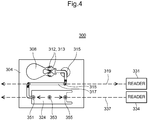
- FIG. 3 there is depicted another lateral flow assay device 100 which is defined by a planar substrate 104 which can be made from a moldable plastic or other suitable non-porous material and having a sample addition zone 108 disposed at one end of a lateral folded fluid flow path extending through a reagent zone 112 containing a detection material, such as a conjugate or other reagent that further extends to at least one detection zone 114 disposed along a flow channel 116 of the device 100, the latter further extending to a wicking zone 120 that defines the opposite end of the lateral fluid flow path.
- a detection material such as a conjugate or other reagent that further extends to at least one detection zone 114 disposed along a flow channel 116 of the device 100, the latter further extending to a wicking zone 120 that defines the opposite end of the lateral fluid flow path.
- the reagents may react with the analyte directly or through a cascade of reactions to form a detectable signal such as a colored or fluorescent molecule.
- the reagent zones 312, 313 include conjugate material.
- conjugate means any moiety bearing both a detection element and a binding partner.
- Each of the first and second microchannels 432, 436 are defined with widths of about 0.05 mm to about 0.1 mm and include expanded portions 448, 452 which according to this embodiment have a length of about 1.1 mm and a width no larger than 0.5 mm, each of the expanded portions creating a read window for purposes of a detection instrument and in which each of the expanded portions 448, 452 are aligned with each other as well as the linear flow channel 224 along the defined detection axis 429.
- a droplet of unconjugated fluorophore could be spotted in the capillary just beyond the junction where the capillary joins the wicking zone.
- This unconjugated material would be easily dissolved by the fluid entering the capillary and would provide a robust signal when the fluid arrives at the end of the capillary (which is within the scan path of the device).
- a very small amount of unconjugated fluorophore could be deposited at the entrance of the flow channel in that conjugate material has not had adequate time to dissolve in this initial front of fluid.
- N fluorescent signals pluripotent assay devices configured with multiple (N) reagent zones
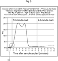
- a total of N fluorescent signals would be generated in the flow channel of the device within a certain time frame. If one or more of the resulting plumes is delayed (e.g., slow flow through the passageway), then the fluorescent signal will feature distinct steps in its rise. If these steps occur over a time frame that is greater than a predetermined threshold, then there may be a reason to believe dissolution of the conjugate material is not occurring normally, resulting in an error. As depicted in Fig. 5 , such a step is shown as indicated by the circled region 336, and indicative of potential delays between the multiple reagent zones.
- the failure to detect the end of the fluorescent signal at all after a maximum elapsed time interval could be indicative of certain anomalies, such as: i) an excessively slow fluid flow rate (or lack of flow rate entirely); ii) an inadequate sample volume; iii) excessive conjugate (detection) material initially present on the assay device or added with sample to the sample addition zone; or iv) another defect in the reagent zone or flow channel that caused the detection material to dissolve too slowly.
Claims (18)
- Verfahren zum Bereitstellen einer Qualitätskontrolle für eine Lateral Flow Assay-Vorrichtung, wobei die Vorrichtung ein Substrat umfasst, das eine Vielzahl eigenständiger Bereiche aufweist, die mindestens einen Probenzuführungsbereich einschließen, mindestens einen Erfassungsbereich stromabwärts des mindestens einen Probenzuführungsbereichs, und mindestens einen Dochtwirkungsbereich stromabwärts des mindestens einen Erfassungsbereichs, wobei jeder dieser Bereiche in fluider Verbindung miteinander entlang eines Fluid-Strömungsweges steht, durch den die Probe unter der Kapillarwirkung des Probenzuführungsbereichs zu dem Dochtwirkungsbereich fließt, wobei das Verfahren die folgenden Schritte umfasst:Zuführen einer Probe zu dem Probenzuführungsbereich und Initiieren eines Timers;Kombinieren von Probe und Reagens, wobei die Probe und das Reagens vor dem Zuführen der Probe in den Probenzuführungsbereich oder auf der Assay-Vorrichtung kombiniert werden können, wobei das Reagens mindestens ein erfassbares Mittel umfasst, das ein erfassbares Signal produziert;Durchführen mindestens einer zeitbezogenen Messung an oder nach dem mindestens einen Erfassungsbereich, um die Gegenwart des erfassbaren Signals in der Lateral Flow Assay-Vorrichtung zu bestimmen, nachdem die Probe dem Probenzuführungsbereich zugeführt wurde; undVergleichen der vergangenen Zeit, berechnet ab dem Initiieren des Timers bis zu der mindestens einen zeitbezogenen Messung zu einer vorbestimmten Schwelle, um zu bestimmen, ob das Gerät ordnungsgemäß arbeitet.
- Verfahren nach Anspruch 1, wobei das erfassbare Mittel ein fluoreszierendes Signal produziert.
- Verfahren nach Anspruch 1, wobei die Assay-Vorrichtung mindestens einen Reagensbereich aufweist, der stromabwärts des Probenzuführungsbereichs angeordnet ist und entlang des Strömungswegs in fluider Verbindung damit steht, wobei der Reagensbereich das mindestens eine erfassbare Mittel enthält.
- Verfahren nach Anspruch 1, ferner den Schritt des Umleitens eines Teils der Probe von dem Strömungsweg der Lateral Flow Assay-Vorrichtung umfassend, um eine Erfassung oder eine fehlende Erfassbarkeit des erfassbaren Signals durch ein Messinstrument zu ermöglichen.
- Verfahren nach Anspruch 4, wobei der Schritt des Umleitens den Schritt des Bereitstellens mindestens eines Kapillarkanals umfasst, wobei sich der mindestens eine Kapillarkanal von dem Strömungsweg erstreckt und sich weiter durch einen linearen Erfassungsweg der Lateral Flow Assay-Vorrichtung erstreckt, der durch das Messinstrument verwendet wird.
- Verfahren nach Anspruch 5, wobei sich der lineare Erfassungsweg entlang eines linearen Teils dieses Strömungswegs erstreckt, der den mindestens einen Erfassungsbereich umfasst.
- Verfahren nach Anspruch 6, wobei sich der mindestens eine Kapillarkanal von dem Dochtwirkungsbereich erstreckt.
- Verfahren nach Anspruch 5, wobei der mindestens eine Kapillarkanal einen vergrößerten Zwischenteil aufweist, der ein Lesefenster bildet, das mit dem Erfassungsbereich ausgerichtet ist.
- Verfahren nach Anspruch 5, wobei der mindestens eine Kapillarkanal belüftet ist.
- Verfahren nach Anspruch 6, wobei der mindestens eine Kapillarkanal die Probe von einem Teil des Strömungswegs vor dem mindestens einen Erfassungsbereich umleitet.
- Verfahren nach Anspruch 7, wobei sich der mindestens eine Kapillarkanal von mindestens einem Eingang und Ausgang des Dochtwirkungsbereichs erstreckt.
- Verfahren nach Anspruch 1, umfassend die folgenden zusätzlichen Schritte:Überwachen mindestens eines Erfassungsbereiches der Vorrichtung;Bestimmen der Dauer, bis die Probe, die das erfassbare Signal trägt, erstmals in Bezug auf den mindestens einen Erfassungsbereich erfasst wird, wobei diese Dauer bei dem Schritt des Zuführens der Probe initiiert wird; undVergleichen der gemessenen Dauer mit einer bekannten Dauer, um sicherzustellen, ob die Lateral Flow Assay-Vorrichtung ordnungsgemäß arbeitet.
- Verfahren nach Anspruch 1, umfassend die folgenden zusätzlichen Schritte:Montieren der Lateral Flow Assay-Vorrichtung in einem Testgerät, vor dem Testen der Vorrichtung, und wobei zunächst keine Probe in dem Testgerät vorhanden ist; undÜberwachung der Vorrichtung mit einem Messinstrument dieses Testgeräts, um zu bestimmen, ob das erfassbare Signal in vorbestimmten Abschnitten der Lateral Flow Assay-Vorrichtung vorhanden ist.
- Verfahren nach Anspruch 1, umfassend die folgenden zusätzlichen Schritte:Überwachung der Vorrichtung am Ende des Dochtwirkungsbereichs mit einem Messinstrument unmittelbar nach dem Zuführen der Probe in den Zuführungsbereich, um zu bestimmen, ob das erfassbare Signal vorhanden ist.
- Verfahren nach Anspruch 1, umfassend die folgenden Schritte:Bestimmen des Zeitpunktes, zu dem die Probe, die das erfassbare Signal trägt, erstmals in einen vorbestimmten Bereich des Dochtwirkungsbereich strömt; und Vergleichen der festgestellten Zeit mit einer bekannten Dauer, um sicherzustellen, ob die Vorrichtung ordnungsgemäß arbeitet.
- Verfahren nach Anspruch 4, wobei das Messinstrument verwendet wird, um die Gegenwart mindestens eines Analyten in dem Erfassungsbereich zu bestimmen, sobald Probe vollständig durch die Lateral Flow-Vorrichtung geflossen ist, wobei das Verfahren ferner die folgenden zusätzlichen Schritte umfasst:Überwachen des mindestens einen Teils der Lateral Flow Assay-Vorrichtung stromabwärts des Reagensbereichs;Bestimmen der Dauer, in der das erfassbare Material in dem mindestens einen Reagensbereich sich vollständig aufgelöst hat, basierend auf dem Überwachungsschritt; undVergleichen der festgestellten Dauer mit einer bekannten Dauer.
- Verfahren nach Anspruch 16, wobei die Erfassung des Analyten nicht erfolgt, bis die festgestellte Dauer mit der bekannten Dauer übereinstimmt.
- Verfahren nach Anspruch 1, umfassend die zusätzlichen folgenden Schritte:Erstellen einer Vielzahl zeitbasierter Messungen an mindestens einem vorbestimmten Abschnitt der Vorrichtung; undErstellen eines Zeitverlaufs des erfassbaren Signals basierend auf den Messungen.
Priority Applications (1)
| Application Number | Priority Date | Filing Date | Title |
|---|---|---|---|
| EP17163375.3A EP3203236A1 (de) | 2012-11-15 | 2013-11-14 | Qualitäts-/prozesssteuerung einer lateralflusstestvorrichtung auf grundlage von flussüberwachung |
Applications Claiming Priority (1)
| Application Number | Priority Date | Filing Date | Title |
|---|---|---|---|
| US201261726933P | 2012-11-15 | 2012-11-15 |
Related Child Applications (2)
| Application Number | Title | Priority Date | Filing Date |
|---|---|---|---|
| EP17163375.3A Division EP3203236A1 (de) | 2012-11-15 | 2013-11-14 | Qualitäts-/prozesssteuerung einer lateralflusstestvorrichtung auf grundlage von flussüberwachung |
| EP17163375.3A Division-Into EP3203236A1 (de) | 2012-11-15 | 2013-11-14 | Qualitäts-/prozesssteuerung einer lateralflusstestvorrichtung auf grundlage von flussüberwachung |
Publications (2)
| Publication Number | Publication Date |
|---|---|
| EP2811301A1 EP2811301A1 (de) | 2014-12-10 |
| EP2811301B1 true EP2811301B1 (de) | 2017-05-10 |
Family
ID=49585295
Family Applications (2)
| Application Number | Title | Priority Date | Filing Date |
|---|---|---|---|
| EP13192854.1A Active EP2811301B1 (de) | 2012-11-15 | 2013-11-14 | Qualitäts-/Prozesssteuerung einer Lateralflusstestvorrichtung auf Grundlage von Flussüberwachung |
| EP17163375.3A Pending EP3203236A1 (de) | 2012-11-15 | 2013-11-14 | Qualitäts-/prozesssteuerung einer lateralflusstestvorrichtung auf grundlage von flussüberwachung |
Family Applications After (1)
| Application Number | Title | Priority Date | Filing Date |
|---|---|---|---|
| EP17163375.3A Pending EP3203236A1 (de) | 2012-11-15 | 2013-11-14 | Qualitäts-/prozesssteuerung einer lateralflusstestvorrichtung auf grundlage von flussüberwachung |
Country Status (7)
| Country | Link |
|---|---|
| US (2) | US9470678B2 (de) |
| EP (2) | EP2811301B1 (de) |
| JP (1) | JP6359263B2 (de) |
| CN (3) | CN113295659A (de) |
| BR (1) | BR102013029443A2 (de) |
| CA (2) | CA3129014A1 (de) |
| RU (1) | RU2013150854A (de) |
Cited By (1)
| Publication number | Priority date | Publication date | Assignee | Title |
|---|---|---|---|---|
| US10921260B2 (en) | 2015-10-09 | 2021-02-16 | Hamamatsu Photonics K.K. | Optical measuring device |
Families Citing this family (15)
| Publication number | Priority date | Publication date | Assignee | Title |
|---|---|---|---|---|
| GB2450351B (en) * | 2007-06-20 | 2012-01-18 | Cozart Bioscience Ltd | Monitoring an Immunoassay |
| WO2012027583A2 (en) | 2010-08-26 | 2012-03-01 | Charm Sciences, Inc. | Lateral flow assay analysis |
| JP6651448B2 (ja) | 2013-12-06 | 2020-02-19 | オーソ−クリニカル・ダイアグノスティックス・インコーポレイテッドOrtho−Clinical Diagnostics, Inc. | 洗浄ポートを有するアッセイデバイス |
| US10031085B2 (en) | 2014-07-24 | 2018-07-24 | Ortho-Clinical Diagnostics, Inc. | Point of care analytical processing system |
| US10073091B2 (en) | 2014-08-08 | 2018-09-11 | Ortho-Clinical Diagnostics, Inc. | Lateral flow assay device |
| US10071373B2 (en) | 2014-08-08 | 2018-09-11 | Ortho-Clinical Diagnostics, Inc. | Lateral-flow assay device having flow constrictions |
| US11033896B2 (en) * | 2014-08-08 | 2021-06-15 | Ortho-Clinical Diagnostics, Inc. | Lateral-flow assay device with filtration flow control |
| US9373561B1 (en) | 2014-12-18 | 2016-06-21 | International Business Machines Corporation | Integrated circuit barrierless microfluidic channel |
| JP6728237B2 (ja) * | 2015-05-19 | 2020-07-22 | オーソ−クリニカル・ダイアグノスティックス・インコーポレイテッドOrtho−Clinical Diagnostics, Inc. | アッセイデバイス中の液体試料の流動を改善する方法 |
| US10656151B2 (en) | 2016-01-29 | 2020-05-19 | Ortho-Clinical Diagnostics, Inc. | Air capillary vent for a lateral flow assay device |
| GB2569554A (en) * | 2017-12-19 | 2019-06-26 | Sumitomo Chemical Co | Apparatus |
| CN111630395A (zh) * | 2018-01-19 | 2020-09-04 | 日东电工株式会社 | 流路、测定用带及测定装置 |
| EP3887827B1 (de) * | 2018-11-28 | 2024-01-17 | 2PI-sigma Corporation | Lateral-flow-test mit gesteuertem konjugat und kontrollierter durchflusszeit |
| CN110251144A (zh) * | 2019-07-19 | 2019-09-20 | 上海析维医疗科技有限公司 | 动物血液采集装置、采集系统及方法 |
| EP4306213A1 (de) * | 2022-07-14 | 2024-01-17 | Sartorius Stedim Biotech GmbH | Verfahren zur herstellung einer rolle von membraneinheiten |
Family Cites Families (51)
| Publication number | Priority date | Publication date | Assignee | Title |
|---|---|---|---|---|
| US220668A (en) * | 1879-10-14 | Improvement in apparatus for testing strain of belts or bands | ||
| EP1248112A3 (de) | 1987-04-27 | 2004-08-25 | Inverness Medical Switzerland GmbH | Immunochromatographische Spezifischebindungsassayvorrichtung |
| US5120643A (en) | 1987-07-13 | 1992-06-09 | Abbott Laboratories | Process for immunochromatography with colloidal particles |
| AU2684488A (en) | 1988-06-27 | 1990-01-04 | Carter-Wallace, Inc. | Test device and method for colored particle immunoassay |
| US5252496A (en) | 1989-12-18 | 1993-10-12 | Princeton Biomeditech Corporation | Carbon black immunochemical label |
| US5409664A (en) * | 1993-09-28 | 1995-04-25 | Chemtrak, Inc. | Laminated assay device |
| US6113855A (en) * | 1996-11-15 | 2000-09-05 | Biosite Diagnostics, Inc. | Devices comprising multiple capillarity inducing surfaces |
| US6139800A (en) | 1997-06-23 | 2000-10-31 | Luminex Corporation | Interlaced lasers for multiple fluorescence measurement |
| US6830731B1 (en) | 1998-01-05 | 2004-12-14 | Biosite, Inc. | Immunoassay fluorometer |
| US6194222B1 (en) * | 1998-01-05 | 2001-02-27 | Biosite Diagnostics, Inc. | Methods for monitoring the status of assays and immunoassays |
| SE521415C2 (sv) | 1998-02-17 | 2003-10-28 | Hans Goeran Evald Martin | Metod för att framställa en gassensortillhörig detektor, samt en detektor framställd enligt metoden |
| WO2000021728A1 (en) | 1998-10-14 | 2000-04-20 | Åmic AB | A matrix and method of producing said matrix |
| US6136610A (en) | 1998-11-23 | 2000-10-24 | Praxsys Biosystems, Inc. | Method and apparatus for performing a lateral flow assay |
| SE9903011D0 (sv) | 1999-08-26 | 1999-08-26 | Aamic Ab | Sätt att framställa en plastprodukt och ett härför utnyttjat plastproduktformande arrangemang |
| DE60042244D1 (de) | 1999-09-10 | 2009-07-02 | Amic Ab | Verfahren zur herstellung einer matrix |
| WO2001038873A2 (en) * | 1999-11-24 | 2001-05-31 | Biotronic Technologies, Inc. | Devices and methods for detecting analytes using electrosensor having capture reagent |
| US20030044869A1 (en) * | 2001-09-04 | 2003-03-06 | Yeung Jupiter M. | Method and apparatus for detecting protein in a sample |
| SE0201738D0 (sv) | 2002-06-07 | 2002-06-07 | Aamic Ab | Micro-fluid structures |
| SE0400662D0 (sv) | 2004-03-24 | 2004-03-24 | Aamic Ab | Assay device and method |
| WO2005100980A2 (en) | 2004-04-06 | 2005-10-27 | Bio/Data Corporation | Disposable test device with sample volume measurement and mixing methods |
| SE527036C2 (sv) | 2004-06-02 | 2005-12-13 | Aamic Ab | Analysanordning med reglerat flöde och motsvarande förfarande |
| US20060023985A1 (en) * | 2004-07-27 | 2006-02-02 | Mircea Gradu | Adaptive bearing system containing a piezoelectric actuator for controlling setting |
| GB0417601D0 (en) * | 2004-08-06 | 2004-09-08 | Inverness Medical Switzerland | Assay device & method |
| JP4455306B2 (ja) * | 2004-12-13 | 2010-04-21 | キヤノン株式会社 | 生化学処理方法 |
| SE529254C2 (sv) | 2005-06-17 | 2007-06-12 | Aamic Ab | Optiskt testsystem |
| SE0501418L (sv) * | 2005-06-20 | 2006-09-26 | Aamic Ab | Metod och medel för att åstadkomma vätsketransport |
| CN101326441B (zh) | 2005-12-08 | 2013-04-10 | 可瑞斯生物概念公司 | 用于快速诊断的试验装置 |
| SE529711C2 (sv) | 2006-03-22 | 2007-11-06 | Aamic Ab | Fluorescensläsare |
| GB2436616A (en) * | 2006-03-29 | 2007-10-03 | Inverness Medical Switzerland | Assay device and method |
| SE531948C2 (sv) | 2006-06-20 | 2009-09-15 | Aamic Ab | Analysanordning för vätskeprover innefattande filter i direkt kontakt med projektioner |
| US20100311186A1 (en) * | 2006-07-28 | 2010-12-09 | Biosite Incorporated | Devices and methods for performing receptor binding assays using magnetic particles |
| JP5004577B2 (ja) * | 2006-12-27 | 2012-08-22 | ローム株式会社 | 液体試薬内蔵型マイクロチップにおける液体試薬の液量および/または品質が正常であるかを判定する方法、および液体試薬内蔵型マイクロチップ |
| EP1947457B1 (de) | 2007-01-17 | 2011-07-13 | AraGen Biotechnology Co. Ltd. | Lateralfluss-Testvorrichtung mit verbesserter Testqualität |
| GB2450351B (en) * | 2007-06-20 | 2012-01-18 | Cozart Bioscience Ltd | Monitoring an Immunoassay |
| US8367424B2 (en) | 2007-10-15 | 2013-02-05 | Rohm Co., Ltd. | Microchip and method of using the same |
| JP5182664B2 (ja) * | 2007-10-31 | 2013-04-17 | ローム株式会社 | マイクロチップおよびその使用方法 |
| JP5132396B2 (ja) * | 2008-04-03 | 2013-01-30 | ローム株式会社 | マイクロチップ |
| WO2009125676A1 (ja) * | 2008-04-09 | 2009-10-15 | コニカミノルタエムジー株式会社 | 検査システム |
| EP2952897B1 (de) * | 2008-04-09 | 2017-03-22 | Becton, Dickinson and Company | Empfindliche immuntests mit beschichteten nanopartikeln |
| WO2009145172A1 (ja) * | 2008-05-29 | 2009-12-03 | 日本電信電話株式会社 | フローセル及び送液方法 |
| CN102939160B (zh) * | 2010-04-16 | 2016-10-12 | 欧普科诊断有限责任公司 | 用于样本分析的系统和装置 |
| WO2012021741A2 (en) | 2010-08-12 | 2012-02-16 | Clontech Laboratories, Inc. | Lateral flow assays for non-diagnostic analytes |
| GB201014316D0 (en) * | 2010-08-27 | 2010-10-13 | Univ Dublin City | A agglutination assay method and device |
| CN102539735A (zh) | 2010-11-12 | 2012-07-04 | 美艾利尔圣地亚哥有限公司 | 集成质量保证标签的测试装置和系统 |
| CA2832494C (en) * | 2011-04-06 | 2019-11-26 | Ortho-Clinical Diagnostics, Inc. | Assay device having rhombus-shaped projections |
| CN102323215A (zh) * | 2011-08-05 | 2012-01-18 | 广州万孚生物技术有限公司 | 分析读数装置及分析读数方法 |
| KR20130085995A (ko) * | 2012-01-20 | 2013-07-30 | 오르토-클리니칼 다이아그노스틱스, 인코포레이티드 | 증가된 감도를 갖는 저체적 분석 장치 |
| JP6133063B2 (ja) * | 2012-01-20 | 2017-05-24 | オーソ−クリニカル・ダイアグノスティックス・インコーポレイテッドOrtho−Clinical Diagnostics, Inc. | 角部周囲の均一な流れを有するアッセイ装置 |
| BR102013001395A2 (pt) * | 2012-01-20 | 2015-11-17 | Ortho Clinical Diagnostics Inc | dispositivo de ensaio tendo múltiplas células de reagentes |
| EP2920591A4 (de) | 2012-11-15 | 2016-10-19 | Ortho Clinical Diagnostics Inc | Kalibrierungsassays mit reaktionszeitnutzung |
| CA2841692C (en) * | 2013-02-12 | 2023-08-22 | Zhong Ding | Reagent zone deposition pattern |
-
2013
- 2013-11-14 CA CA3129014A patent/CA3129014A1/en active Pending
- 2013-11-14 RU RU2013150854/15A patent/RU2013150854A/ru not_active Application Discontinuation
- 2013-11-14 CA CA2833532A patent/CA2833532C/en active Active
- 2013-11-14 JP JP2013235693A patent/JP6359263B2/ja active Active
- 2013-11-14 EP EP13192854.1A patent/EP2811301B1/de active Active
- 2013-11-14 EP EP17163375.3A patent/EP3203236A1/de active Pending
- 2013-11-14 BR BRBR102013029443-8A patent/BR102013029443A2/pt not_active IP Right Cessation
- 2013-11-15 US US14/081,467 patent/US9470678B2/en active Active
- 2013-11-15 CN CN202110375285.7A patent/CN113295659A/zh active Pending
- 2013-11-15 CN CN201310574378.8A patent/CN103822904A/zh active Pending
- 2013-11-15 CN CN201910669891.2A patent/CN110579599A/zh active Pending
-
2016
- 2016-09-23 US US15/274,495 patent/US10509031B2/en active Active
Cited By (1)
| Publication number | Priority date | Publication date | Assignee | Title |
|---|---|---|---|---|
| US10921260B2 (en) | 2015-10-09 | 2021-02-16 | Hamamatsu Photonics K.K. | Optical measuring device |
Also Published As
| Publication number | Publication date |
|---|---|
| CA2833532A1 (en) | 2014-05-15 |
| EP2811301A1 (de) | 2014-12-10 |
| BR102013029443A2 (pt) | 2014-10-29 |
| JP6359263B2 (ja) | 2018-07-18 |
| CA3129014A1 (en) | 2014-05-15 |
| RU2013150854A (ru) | 2015-05-20 |
| US9470678B2 (en) | 2016-10-18 |
| US20140141527A1 (en) | 2014-05-22 |
| EP3203236A1 (de) | 2017-08-09 |
| US20170010262A1 (en) | 2017-01-12 |
| CN113295659A (zh) | 2021-08-24 |
| JP2014098700A (ja) | 2014-05-29 |
| CN103822904A (zh) | 2014-05-28 |
| US10509031B2 (en) | 2019-12-17 |
| CN110579599A (zh) | 2019-12-17 |
| CA2833532C (en) | 2021-10-26 |
Similar Documents
| Publication | Publication Date | Title |
|---|---|---|
| US10509031B2 (en) | Quality/process control of a lateral flow assay device based on flow monitoring | |
| EP3194965B1 (de) | Querfluss-assay-vorrichtung | |
| US11260390B2 (en) | Lateral-flow assay device having flow constrictions | |
| US20210268496A1 (en) | Lateral-flow assay device with filtration flow control | |
| US11287424B2 (en) | Calibrating assays using reaction time | |
| US9903858B2 (en) | Multiplexing with single sample metering event to increase throughput |
Legal Events
| Date | Code | Title | Description |
|---|---|---|---|
| PUAI | Public reference made under article 153(3) epc to a published international application that has entered the european phase |
Free format text: ORIGINAL CODE: 0009012 |
|
| 17P | Request for examination filed |
Effective date: 20131114 |
|
| AK | Designated contracting states |
Kind code of ref document: A1 Designated state(s): AL AT BE BG CH CY CZ DE DK EE ES FI FR GB GR HR HU IE IS IT LI LT LU LV MC MK MT NL NO PL PT RO RS SE SI SK SM TR |
|
| AX | Request for extension of the european patent |
Extension state: BA ME |
|
| R17P | Request for examination filed (corrected) |
Effective date: 20150608 |
|
| RBV | Designated contracting states (corrected) |
Designated state(s): AL AT BE BG CH CY CZ DE DK EE ES FI FR GB GR HR HU IE IS IT LI LT LU LV MC MK MT NL NO PL PT RO RS SE SI SK SM TR |
|
| 17Q | First examination report despatched |
Effective date: 20160201 |
|
| GRAP | Despatch of communication of intention to grant a patent |
Free format text: ORIGINAL CODE: EPIDOSNIGR1 |
|
| INTG | Intention to grant announced |
Effective date: 20161128 |
|
| GRAS | Grant fee paid |
Free format text: ORIGINAL CODE: EPIDOSNIGR3 |
|
| GRAA | (expected) grant |
Free format text: ORIGINAL CODE: 0009210 |
|
| AK | Designated contracting states |
Kind code of ref document: B1 Designated state(s): AL AT BE BG CH CY CZ DE DK EE ES FI FR GB GR HR HU IE IS IT LI LT LU LV MC MK MT NL NO PL PT RO RS SE SI SK SM TR |
|
| REG | Reference to a national code |
Ref country code: GB Ref legal event code: FG4D |
|
| REG | Reference to a national code |
Ref country code: AT Ref legal event code: REF Ref document number: 892895 Country of ref document: AT Kind code of ref document: T Effective date: 20170515 Ref country code: CH Ref legal event code: EP |
|
| REG | Reference to a national code |
Ref country code: IE Ref legal event code: FG4D |
|
| REG | Reference to a national code |
Ref country code: DE Ref legal event code: R096 Ref document number: 602013020882 Country of ref document: DE |
|
| REG | Reference to a national code |
Ref country code: SE Ref legal event code: TRGR |
|
| REG | Reference to a national code |
Ref country code: NL Ref legal event code: MP Effective date: 20170510 |
|
| REG | Reference to a national code |
Ref country code: LT Ref legal event code: MG4D |
|
| REG | Reference to a national code |
Ref country code: FR Ref legal event code: PLFP Year of fee payment: 5 |
|
| REG | Reference to a national code |
Ref country code: AT Ref legal event code: MK05 Ref document number: 892895 Country of ref document: AT Kind code of ref document: T Effective date: 20170510 |
|
| PG25 | Lapsed in a contracting state [announced via postgrant information from national office to epo] |
Ref country code: ES Free format text: LAPSE BECAUSE OF FAILURE TO SUBMIT A TRANSLATION OF THE DESCRIPTION OR TO PAY THE FEE WITHIN THE PRESCRIBED TIME-LIMIT Effective date: 20170510 Ref country code: NO Free format text: LAPSE BECAUSE OF FAILURE TO SUBMIT A TRANSLATION OF THE DESCRIPTION OR TO PAY THE FEE WITHIN THE PRESCRIBED TIME-LIMIT Effective date: 20170810 Ref country code: FI Free format text: LAPSE BECAUSE OF FAILURE TO SUBMIT A TRANSLATION OF THE DESCRIPTION OR TO PAY THE FEE WITHIN THE PRESCRIBED TIME-LIMIT Effective date: 20170510 Ref country code: HR Free format text: LAPSE BECAUSE OF FAILURE TO SUBMIT A TRANSLATION OF THE DESCRIPTION OR TO PAY THE FEE WITHIN THE PRESCRIBED TIME-LIMIT Effective date: 20170510 Ref country code: GR Free format text: LAPSE BECAUSE OF FAILURE TO SUBMIT A TRANSLATION OF THE DESCRIPTION OR TO PAY THE FEE WITHIN THE PRESCRIBED TIME-LIMIT Effective date: 20170811 Ref country code: AT Free format text: LAPSE BECAUSE OF FAILURE TO SUBMIT A TRANSLATION OF THE DESCRIPTION OR TO PAY THE FEE WITHIN THE PRESCRIBED TIME-LIMIT Effective date: 20170510 Ref country code: LT Free format text: LAPSE BECAUSE OF FAILURE TO SUBMIT A TRANSLATION OF THE DESCRIPTION OR TO PAY THE FEE WITHIN THE PRESCRIBED TIME-LIMIT Effective date: 20170510 |
|
| PG25 | Lapsed in a contracting state [announced via postgrant information from national office to epo] |
Ref country code: RS Free format text: LAPSE BECAUSE OF FAILURE TO SUBMIT A TRANSLATION OF THE DESCRIPTION OR TO PAY THE FEE WITHIN THE PRESCRIBED TIME-LIMIT Effective date: 20170510 Ref country code: BG Free format text: LAPSE BECAUSE OF FAILURE TO SUBMIT A TRANSLATION OF THE DESCRIPTION OR TO PAY THE FEE WITHIN THE PRESCRIBED TIME-LIMIT Effective date: 20170810 Ref country code: NL Free format text: LAPSE BECAUSE OF FAILURE TO SUBMIT A TRANSLATION OF THE DESCRIPTION OR TO PAY THE FEE WITHIN THE PRESCRIBED TIME-LIMIT Effective date: 20170510 Ref country code: PL Free format text: LAPSE BECAUSE OF FAILURE TO SUBMIT A TRANSLATION OF THE DESCRIPTION OR TO PAY THE FEE WITHIN THE PRESCRIBED TIME-LIMIT Effective date: 20170510 Ref country code: IS Free format text: LAPSE BECAUSE OF FAILURE TO SUBMIT A TRANSLATION OF THE DESCRIPTION OR TO PAY THE FEE WITHIN THE PRESCRIBED TIME-LIMIT Effective date: 20170910 Ref country code: LV Free format text: LAPSE BECAUSE OF FAILURE TO SUBMIT A TRANSLATION OF THE DESCRIPTION OR TO PAY THE FEE WITHIN THE PRESCRIBED TIME-LIMIT Effective date: 20170510 |
|
| PG25 | Lapsed in a contracting state [announced via postgrant information from national office to epo] |
Ref country code: SK Free format text: LAPSE BECAUSE OF FAILURE TO SUBMIT A TRANSLATION OF THE DESCRIPTION OR TO PAY THE FEE WITHIN THE PRESCRIBED TIME-LIMIT Effective date: 20170510 Ref country code: EE Free format text: LAPSE BECAUSE OF FAILURE TO SUBMIT A TRANSLATION OF THE DESCRIPTION OR TO PAY THE FEE WITHIN THE PRESCRIBED TIME-LIMIT Effective date: 20170510 Ref country code: CZ Free format text: LAPSE BECAUSE OF FAILURE TO SUBMIT A TRANSLATION OF THE DESCRIPTION OR TO PAY THE FEE WITHIN THE PRESCRIBED TIME-LIMIT Effective date: 20170510 Ref country code: DK Free format text: LAPSE BECAUSE OF FAILURE TO SUBMIT A TRANSLATION OF THE DESCRIPTION OR TO PAY THE FEE WITHIN THE PRESCRIBED TIME-LIMIT Effective date: 20170510 Ref country code: RO Free format text: LAPSE BECAUSE OF FAILURE TO SUBMIT A TRANSLATION OF THE DESCRIPTION OR TO PAY THE FEE WITHIN THE PRESCRIBED TIME-LIMIT Effective date: 20170510 |
|
| REG | Reference to a national code |
Ref country code: DE Ref legal event code: R097 Ref document number: 602013020882 Country of ref document: DE |
|
| PG25 | Lapsed in a contracting state [announced via postgrant information from national office to epo] |
Ref country code: SM Free format text: LAPSE BECAUSE OF FAILURE TO SUBMIT A TRANSLATION OF THE DESCRIPTION OR TO PAY THE FEE WITHIN THE PRESCRIBED TIME-LIMIT Effective date: 20170510 |
|
| PLBE | No opposition filed within time limit |
Free format text: ORIGINAL CODE: 0009261 |
|
| STAA | Information on the status of an ep patent application or granted ep patent |
Free format text: STATUS: NO OPPOSITION FILED WITHIN TIME LIMIT |
|
| 26N | No opposition filed |
Effective date: 20180213 |
|
| PG25 | Lapsed in a contracting state [announced via postgrant information from national office to epo] |
Ref country code: SI Free format text: LAPSE BECAUSE OF FAILURE TO SUBMIT A TRANSLATION OF THE DESCRIPTION OR TO PAY THE FEE WITHIN THE PRESCRIBED TIME-LIMIT Effective date: 20170510 |
|
| PG25 | Lapsed in a contracting state [announced via postgrant information from national office to epo] |
Ref country code: MC Free format text: LAPSE BECAUSE OF FAILURE TO SUBMIT A TRANSLATION OF THE DESCRIPTION OR TO PAY THE FEE WITHIN THE PRESCRIBED TIME-LIMIT Effective date: 20170510 |
|
| PG25 | Lapsed in a contracting state [announced via postgrant information from national office to epo] |
Ref country code: LU Free format text: LAPSE BECAUSE OF NON-PAYMENT OF DUE FEES Effective date: 20171114 |
|
| REG | Reference to a national code |
Ref country code: BE Ref legal event code: MM Effective date: 20171130 |
|
| PG25 | Lapsed in a contracting state [announced via postgrant information from national office to epo] |
Ref country code: MT Free format text: LAPSE BECAUSE OF NON-PAYMENT OF DUE FEES Effective date: 20171114 |
|
| REG | Reference to a national code |
Ref country code: FR Ref legal event code: PLFP Year of fee payment: 6 |
|
| PG25 | Lapsed in a contracting state [announced via postgrant information from national office to epo] |
Ref country code: BE Free format text: LAPSE BECAUSE OF NON-PAYMENT OF DUE FEES Effective date: 20171130 |
|
| PG25 | Lapsed in a contracting state [announced via postgrant information from national office to epo] |
Ref country code: HU Free format text: LAPSE BECAUSE OF FAILURE TO SUBMIT A TRANSLATION OF THE DESCRIPTION OR TO PAY THE FEE WITHIN THE PRESCRIBED TIME-LIMIT; INVALID AB INITIO Effective date: 20131114 |
|
| PG25 | Lapsed in a contracting state [announced via postgrant information from national office to epo] |
Ref country code: CY Free format text: LAPSE BECAUSE OF FAILURE TO SUBMIT A TRANSLATION OF THE DESCRIPTION OR TO PAY THE FEE WITHIN THE PRESCRIBED TIME-LIMIT Effective date: 20170510 |
|
| PG25 | Lapsed in a contracting state [announced via postgrant information from national office to epo] |
Ref country code: MK Free format text: LAPSE BECAUSE OF FAILURE TO SUBMIT A TRANSLATION OF THE DESCRIPTION OR TO PAY THE FEE WITHIN THE PRESCRIBED TIME-LIMIT Effective date: 20170510 |
|
| PG25 | Lapsed in a contracting state [announced via postgrant information from national office to epo] |
Ref country code: TR Free format text: LAPSE BECAUSE OF FAILURE TO SUBMIT A TRANSLATION OF THE DESCRIPTION OR TO PAY THE FEE WITHIN THE PRESCRIBED TIME-LIMIT Effective date: 20170510 |
|
| PG25 | Lapsed in a contracting state [announced via postgrant information from national office to epo] |
Ref country code: PT Free format text: LAPSE BECAUSE OF FAILURE TO SUBMIT A TRANSLATION OF THE DESCRIPTION OR TO PAY THE FEE WITHIN THE PRESCRIBED TIME-LIMIT Effective date: 20170510 |
|
| PG25 | Lapsed in a contracting state [announced via postgrant information from national office to epo] |
Ref country code: AL Free format text: LAPSE BECAUSE OF FAILURE TO SUBMIT A TRANSLATION OF THE DESCRIPTION OR TO PAY THE FEE WITHIN THE PRESCRIBED TIME-LIMIT Effective date: 20170510 |
|
| P01 | Opt-out of the competence of the unified patent court (upc) registered |
Effective date: 20230718 |
|
| PGFP | Annual fee paid to national office [announced via postgrant information from national office to epo] |
Ref country code: IE Payment date: 20230912 Year of fee payment: 11 Ref country code: GB Payment date: 20230921 Year of fee payment: 11 |
|
| PGFP | Annual fee paid to national office [announced via postgrant information from national office to epo] |
Ref country code: SE Payment date: 20230912 Year of fee payment: 11 Ref country code: FR Payment date: 20230911 Year of fee payment: 11 |
|
| PGFP | Annual fee paid to national office [announced via postgrant information from national office to epo] |
Ref country code: IT Payment date: 20231010 Year of fee payment: 11 Ref country code: DE Payment date: 20230919 Year of fee payment: 11 Ref country code: CH Payment date: 20231201 Year of fee payment: 11 |