EP2811096B1 - Closing device for door or window wings - Google Patents
Closing device for door or window wings Download PDFInfo
- Publication number
- EP2811096B1 EP2811096B1 EP14170371.0A EP14170371A EP2811096B1 EP 2811096 B1 EP2811096 B1 EP 2811096B1 EP 14170371 A EP14170371 A EP 14170371A EP 2811096 B1 EP2811096 B1 EP 2811096B1
- Authority
- EP
- European Patent Office
- Prior art keywords
- spring
- piston rod
- piston
- driver
- wing
- Prior art date
- Legal status (The legal status is an assumption and is not a legal conclusion. Google has not performed a legal analysis and makes no representation as to the accuracy of the status listed.)
- Active
Links
Images


Classifications
-
- E—FIXED CONSTRUCTIONS
- E05—LOCKS; KEYS; WINDOW OR DOOR FITTINGS; SAFES
- E05F—DEVICES FOR MOVING WINGS INTO OPEN OR CLOSED POSITION; CHECKS FOR WINGS; WING FITTINGS NOT OTHERWISE PROVIDED FOR, CONCERNED WITH THE FUNCTIONING OF THE WING
- E05F3/00—Closers or openers with braking devices, e.g. checks; Construction of pneumatic or liquid braking devices
- E05F3/22—Additional arrangements for closers, e.g. for holding the wing in opened or other position
- E05F3/221—Mechanical power-locks, e.g. for holding the wing open or for free-moving zones
-
- E—FIXED CONSTRUCTIONS
- E05—LOCKS; KEYS; WINDOW OR DOOR FITTINGS; SAFES
- E05F—DEVICES FOR MOVING WINGS INTO OPEN OR CLOSED POSITION; CHECKS FOR WINGS; WING FITTINGS NOT OTHERWISE PROVIDED FOR, CONCERNED WITH THE FUNCTIONING OF THE WING
- E05F3/00—Closers or openers with braking devices, e.g. checks; Construction of pneumatic or liquid braking devices
- E05F3/04—Closers or openers with braking devices, e.g. checks; Construction of pneumatic or liquid braking devices with liquid piston brakes
- E05F3/10—Closers or openers with braking devices, e.g. checks; Construction of pneumatic or liquid braking devices with liquid piston brakes with a spring, other than a torsion spring, and a piston, the axes of which are the same or lie in the same direction
- E05F3/102—Closers or openers with braking devices, e.g. checks; Construction of pneumatic or liquid braking devices with liquid piston brakes with a spring, other than a torsion spring, and a piston, the axes of which are the same or lie in the same direction with rack-and-pinion transmission between driving shaft and piston within the closer housing
-
- E—FIXED CONSTRUCTIONS
- E05—LOCKS; KEYS; WINDOW OR DOOR FITTINGS; SAFES
- E05Y—INDEXING SCHEME RELATING TO HINGES OR OTHER SUSPENSION DEVICES FOR DOORS, WINDOWS OR WINGS AND DEVICES FOR MOVING WINGS INTO OPEN OR CLOSED POSITION, CHECKS FOR WINGS AND WING FITTINGS NOT OTHERWISE PROVIDED FOR, CONCERNED WITH THE FUNCTIONING OF THE WING
- E05Y2201/00—Constructional elements; Accessories therefore
- E05Y2201/20—Brakes; Disengaging means, e.g. clutches; Holders, e.g. locks; Stops; Accessories therefore
- E05Y2201/214—Disengaging means
Definitions
- the invention relates to a collection device for a wing of a door or a window according to the preamble of claim 1.
- a door closer with a switchable freewheel function known.
- a piston In a filled with a hydraulic fluid housing, a piston is slidably disposed against a spring.
- the piston is connected via a toothing and a pinion via a lever arrangement with a wing of a door.
- the spring which is supported on the piston is at the other end supported on a separating piston which is likewise displaceable in the housing and which is hydraulically switchable. Thereby, the spring can be kept in a tensioned state between the piston and the separating piston, whereby a freewheel for the wing of the door can be effected.
- the arrangement is complex, and it is a hydraulic switching device required. An automatic collection of the freely movable wing near the closed position of the wing in the closed position is not provided.
- a locking device for a door closer wherein a cam gear of the door closer can be blocked by designed as balls locking members are applied to a cross-sectional widening of a displaceable hollow cylinder by the inclined surface of a cone part and supported against the inner surface of the hollow cylinder outwardly.
- the disadvantage is only a detection of the door closer in an open position of the wing of the door, the determination is complicated and costly switched by an electromagnet.
- a door closer which has a door locking device. By overriding two balls by force the door is detected in the open position.
- a door closer is known, on the one hand a conventional damper with a piston in a cylinder, by a push spring in the closing direction and, on the other hand, a damper assembly associated with drive springs to regulate the rate of closing the door.
- the DE 10 2009 000 539 A1 discloses a door closer with a housing and with a guided in the housing, a piston rod having pistons. Furthermore, a spring is arranged in the housing, which is acted upon when opening the wing and is designed for automatic closing of the wing. It is provided a locking device for detecting the piston in the working cylinder, with an axial blocking possibility of the piston via locking means of the locking device. To determine the piston in the closing direction, a holding pin arranged on the piston rod is supported on the housing with the locking device activated via a detent rocker against the force of the spring.
- the disadvantage here is a complex and costly locking the spring of the door closer by switching an electromagnet. A retraction of the wing in the closed position is not possible with detected spring.
- the invention has for its object to provide a collection device for a wing of a door or a window, wherein the wing is largely free to move, but also safely guided in its closed position.
- the collection device is provided for a pivotable door whose wings are mounted in hinges on a frame.
- the collection device is constructed so that the wing is freely movable over a wide range, as if no device is arranged on the door. In the area near the closed position of the wing of the wing is actively drawn into this closed position. The retraction movement is additionally damped to avoid a sharp slamming of the wing.
- the pull-in damping may optionally provide a position for the open position of the wing, wherein the wing is pulled close to this open position in this position.
- the collection device has a spring formed as energy storage, which attracts the wing near the closed position.
- at least one freewheel device is provided, which makes it possible to decouple the wing from the energy storage.
- the wing of the door is operatively connected via a linkage to a pinion which meshes with a toothing of a piston displaceably arranged in the draw-in device.
- a piston rod is arranged, with which the piston can be coupled via the freewheel device with the spring.
- the coupling is only at small opening angles of the wing of the door, so that afterwards the wing is freely movable.
- an additional coupling takes place in an open position of the wing, so that the wing is raised to this open position, wherein the wing is also freely movable in the area between the open position and the area near the closed position, from which the entry into the closed position ,
- FIG.1 an intake device 3 integrated in a wing 1 of a door for the pivotally hinged wing 1 together with an associated frame 2 is shown.
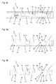
- FIGS. 2a to 2c and FIGS. 3a and 3b show exemplary embodiments of simple embodiments of collection devices 3 which are not according to the invention.
- the intake device 3 has a filled with a hydraulic fluid housing 7, in which the shaft 8 is rotatably mounted.
- a piston 10 is arranged, which comprises a toothing 11, a damping piston 12 and a spring piston 14.
- the receiving space 9 of the housing 7 can be sealingly closed on one or both sides with a closure lid.
- a pinion 13 of the shaft 8 cooperates with the toothing 11 of the piston 10 to its displacement.
- the damping piston 12 and the spring piston 14 are sealed against the inner wall of the receiving space 9 of the housing 7 out.
- a spring 15 act as energy storage, the spring 15 is partially ineffective switchable by a freewheel device 16.
- the spring 15 can be supported at the end on the housing 7 or on the spring-side closure lid.
- the damping piston 12 closes a damping chamber 17 within the filled with hydraulic fluid receiving space 9 in the housing 7, wherein a valve 18 may be arranged in the damping piston 12, with which an overflow of the hydraulic fluid from or into the damping chamber 17 and thus the damping behavior of the collection device. 3 can be influenced.
- a valve 18 may also be arranged to allow at least in one direction of movement, a flow through the spring piston 14.
- one or more overflow channels can be arranged in the housing 7, in which externally accessible, adjustable valves 18 can be arranged to influence the behavior of the collection device.
- a cylindrical piston rod 19 for example, by screwing in a thread on the spring piston 14 or by pressing, set.
- the piston rod 19 is tapered, wherein a circumferential slope 20 is designed to control the freewheel device 16.
- a receptacle for the engagement of a tool may be provided at the end on the piston rod 19 in order to screw the piston rod 19 into the thread in the spring piston 14.
- the piston rod 19 is guided in a driver 21, which in turn is received in a locking sleeve 22 and guided.
- the driver 21 has in the direction of the spring 15 toward a collar 25 as a contact surface for the spring 15.
- the locking sleeve 22 has circumferentially advantageous a plurality of spaced recesses 26, in which locking elements 23 are arranged.
- the latching sleeve 22 is supported on a support ring 24 in the housing 7 in the direction of the spring piston 14.
- the locking elements 23 may be balls.
- a rectangular or polygonal, for example hexagonal, piston rod 19 is conceivable, wherein the locking elements 23 may then be rollers.
- the driver 21 and the locking sleeve 22 are accordingly adapted to form the rectangular or polygonal shape.
- Fig. 2a is the collection device 3 in the starting position with the wing 1 closed the door or window.
- the prestressed mounted spring 15 is supported on the end side on the closure lid of the receiving space 9.
- Andernends is the spring 15 on the collar 25 of the driver 21, whereby the Driver 21 is acted upon in the direction of the spring piston 12.
- the locking elements 23 are located in the tapered region of the piston rod 19 in abutment with the bevel 20.
- the recorded in the recesses 26 of the driver 21 locking elements 23 are located within the locking sleeve 22. There is a coupling between the piston rod 19 and the Driver 21.
- Fig. 2b shows the collection device 3 in a position with about 30 ° open wing 1.
- the piston rod 19 is displaced in the direction of the spring 15, wherein the voltage applied to the bevel 20 and in the recesses 26 of the driver 21st received latching elements 23 of the driver 21 is taken in the direction of the spring 15, whereby the resting on the collar 25 of the driver 21 spring 15 is tensioned according to the displacement.
- the transition is shown at which the locking elements 23 can just leave the area within the locking sleeve 22, since the locking elements 23 can escape through the recesses 26 in the extended area behind the locking sleeve 22.
- the locking elements 23 are therefore urged along the slope 20 to the outside, whereby the locking elements 23 slide on the outer diameter of the piston rod 19.
- Fig. 2c is the collection device 3 in still open position of the wing 1, for example, at about 70 ° shown.
- the locking elements 23 support the force of the spring 15 against the latching sleeve 22 from.
- the spring 15 is thus ineffective with respect to the piston 10. A movement of the piston 10 is freely possible in this freewheel area without the action of force by the spring 15, whereby the wing 1 of the door can be moved freely.
- the position is again in accordance with Fig. 2b achieved, wherein the locking elements 23 by the force of the spring 15 along a arranged on the latching sleeve 22 sleeve slope 27 in the recess 26 in the driver 21 in the tapered region of the piston rod 19 in abutment with the bevels 20 are pushed back.
- This results in a force transmission of the force of the spring 15 via the driver 21, the locking elements 23 and the bevels 20 on the piston rod 19, whereby the piston 10 is moved in the closing direction of the wing 1.
- the wing 1 is thus guided from the here exemplarily selected opening angle of about 30 ° by the collection device 3 in the closed position.
- FIGS. 3a and 3b a further non-inventive embodiment is shown, wherein the piston rod 19 has the locking elements 23 adapted shaped recesses 28 for controlling the freewheel device 16.
- the piston rod 19 has the locking elements 23 adapted shaped recesses 28 for controlling the freewheel device 16.
- a plurality of recesses 28 and an annular circumferential recess 28 may be provided on the piston rod 19.
- the latching sleeve 22 which is fixed here directly in the receiving space 9
- corresponding depressions 29 or a depression 29 designed as a peripheral groove are arranged for engagement of the latching elements 23.
- Fig. 3a shown starting position which to Fig.
- the locking elements 23 are guided in the recesses 28 of the piston rod 19 and in the recesses 26 of the driver 21 within the cylindrical inner wall of the latching sleeve 22.
- the wing 1 Upon movement of the wing 1 in the opening direction of the piston 10 is displaced in the direction of the spring 15, whereby the coupled via the locking elements 23 with the piston rod 19 driver 21, which rests with its collar 23 on the spring 15, the spring 15 biases.
- a further, second freewheel device 16 is provided, wherein the first, the spring piston facing freewheel device 16 and the end arranged in the receiving space 9 second freewheel device 16 are constructed to be identical, the second freewheel device is arranged vice versa, so that the driver 21 with their Align frets 25 each other and so both freewheel devices 16 cooperate with the interposed spring 15.
- This is in addition to the entry of the wing 1 in its closed position, a mounting of the wing 1 in an open position possible. In the intermediate area, the free-running function is completely retained.
- piston rod 19 By the piston rod 19, in particular by the arranged on the piston rod 19 recess 28.
- the piston rod 19 is longer here and has for the second freewheel device 16 an additional circumferential taper 31, which includes the function of the recess 28.
- first freewheel device 16 is in the same position, as in the simple embodiments according to the FIGS. 2a . 3a
- the locking elements 23 engage in the recesses 28 of the piston rod 19 and in the recesses 26 of the first driver 21, whereby the first driver 21 is coupled to the piston rod 19.
- second freewheel device 16 is located in the freewheel area.
- the second driver 21 is displaced in the direction of the spring 15, wherein the locking elements 23 in the recesses 29 of the second detent sleeve 22 and are received in the recesses 26 of the driver 21.
- the spring 15 is supported on the second driver 21 and further on the second latching element 22.
- the piston 10 is moved with the piston rod 19 to the right, whereby the spring 15 is tensioned by the coupling of the piston rod 19 with the first driver 21 of the first freewheel device 16, as shown in the Fig. 4b is shown.
- the second freewheel device 16 is still in the freewheel area, wherein the second driver 21, as described above, is decoupled.
- the first freewheel device 16 just at the beginning of the transition into the freewheel area, wherein the locking elements 23 can escape into the recesses 29 of the first latching sleeve 22 and the tension of the spring 15 is detected by the first driver 21.
- the Fig. 4b In the position according to Fig. 4b is the first freewheel device 16 just at the beginning of the transition into the freewheel area, wherein the locking elements 23 can escape into the recesses 29 of the first latching sleeve 22 and the tension of the spring 15 is detected by the first driver 21.
- the collection device 3 is shown in the area in which both the first and the second freewheel device 16 are in the freewheeling area, wherein both drivers 21 are detected, and so the spring 15 is maximally tensioned.
- the second freewheel device 16 is according to Fig. 4c just arrived at the end of their freewheel area.
- the locking elements 23 due to the force acting on the second driver 21 of the tensioned spring 15 in the taper 31 on the piston rod 19 from the recesses 29 of the second detent sleeve 22 back out.
- the depressions 29 of the second detent sleeve can also have a depression outlet 30.
- the piston rod 19 is acted upon by the second driver 21 and the locking elements 23 which abut against the right flank 32 of the taper 31, with the spring 15, whereby the piston rod 19 and the piston 10 in the Fig. 4d is moved to the right and the wing 1 is raised in the opening direction. This causes a movement of the wing 1 in an open position.
- the position of this open position of the wing 1 can be adjusted by the end provided on the retraction device 3, accessible from the outside retraction stop 33, with which the possible displacement of the second driver 21 can be limited in the opening direction of the wing 1, as shown in the Fig. 4e is shown.
- the possible open position of the wing 1 in the desired opening position, in which the wing 1 is mounted can be adjusted.
- the retraction stop 33 is received in a thread at the end of the receiving space 9 and is thus adjustable by rotation with respect to the second driver 21.
- the end stop 33 may be received in a thread in the retraction stop 34 and is adjustable by rotation with respect to the piston rod 19.
- the end stop 34 is adjusted by adjusting the retraction stop 33.
- the piston rod 19 passes with the recesses 28 within the first driver 21 in the region of the locking elements 23, whereby the locking elements 23 due to the acted upon by the spring 15 first driver 21 from the recesses 29 of the first detent sleeve 22 in the recesses 28 are pushed into it.
- the piston rod 19 is coupled to the first driver 21 and thus with the tensioned spring 15, whereby the collection of the wing 1 is effected by the collection device 3 in its closed position.
- FIGS. 5a to 5c an inventive embodiment is shown schematically in section.
- the structure of the intake device 3 corresponds to the embodiments described above, so that here only the piston rod 19 and the region of the freewheel devices 16 is shown.
- the piston rod 19 is connected on the left side with the piston 10.
- the first and the second freewheel device 16 are in this case arranged in a locking sleeve designed as a detent sleeve 22, wherein each freewheel device 16 is associated with a recess 29.
- the detent sleeve 22 may have end closure elements through which the piston rod 19 is guided, whereby the detent capsule is formed.
- the locking capsule can be used as a unit in the receiving space 9 of the collection device.
- two springs 35, 36 are provided.
- the springs 35, 36 are supported at one end on the associated driver 21 and at the other end on the locking capsule.
- the springs 35, 36 may be supported for example by means inserted into grooves in the receiving space 9 retaining rings.
- the depressions 29 can be incorporated into the wall of the receiving space 9 in the housing 7.
- Fig. 5a again shows the starting position with the wing closed 1 of the intake device 3.
- the first, left freewheel device 16 is located in the freewheel area, wherein the piston rod 19 is uninfluenced by this displaced.
- the locking elements 23 are received in the recesses 29 of the locking capsule, and the associated first driver 21 is blocked, whereby the first, biased spring 35 is blocked.
- For the second, right freewheel device 16 there is the coupling between the piston rod 19 and the acted upon by the second spring 36 second driver 21 by the locking elements 23 engage in the recesses 28 of the piston rod 19.
- the second spring 36 is in a relaxed state.
- the second spring 36 is tensioned by the existing coupling of the piston rod 19 in the second freewheel device 16 until the second freewheel device 16 is displaced so far that the latching elements 23 engage in the depressions 29 in the detent capsule that the second freewheel device 16 merges into the freewheeling area, as in the Fig. 5b is shown. Both springs 35, 36 are stretched, and the piston rod 19, and thus the retraction device 3, is completely freewheeling, and the wing 1 is freely movable.
Description
Die Erfindung betrifft eine Einzugsvorrichtung für einen Flügel einer Tür oder eines Fensters nach dem Oberbegriff des Anspruchs 1.The invention relates to a collection device for a wing of a door or a window according to the preamble of
Aus der
Aus der
In der
Aus der
Die
Nachteilig erfolgt hier ein aufwändiges und kostenintensives Feststellen der Feder des Türschließers durch Schalten eines Elektromagneten. Ein Einzug des Flügels in die Schließlage ist bei festgestellter Feder nicht möglich.The disadvantage here is a complex and costly locking the spring of the door closer by switching an electromagnet. A retraction of the wing in the closed position is not possible with detected spring.
Der Erfindung liegt die Aufgabe zugrunde, eine Einzugsvorrichtung für einen Flügel einer Tür oder eines Fensters zu schaffen, wobei der Flügel weitgehend frei bewegbar ist, jedoch auch sicher in seine Schließlage geführt wird.The invention has for its object to provide a collection device for a wing of a door or a window, wherein the wing is largely free to move, but also safely guided in its closed position.
Die Aufgabe wird durch die Merkmale des Anspruchs 1 gelöst.The object is solved by the features of
Die Unteransprüche bilden vorteilhafte Ausgestaltungsmöglichkeiten der Erfindung.The subclaims form advantageous embodiments of the invention.
Die Einzugsvorrichtung ist für eine schwenkbare Tür vorgesehen, deren Flügel in Scharnieren an einem Rahmen gelagert ist. Die Einzugsvorrichtung ist so aufgebaut, dass der Flügel über einen weiten Bereich frei bewegbar ist, so als sei keine Vorrichtung an der Türe angeordnet. Im Bereich nahe der Geschlossenstellung des Flügels wird der Flügel aktiv in diese Geschlossenstellung eingezogen. Dabei wird die Einzugsbewegung zusätzlich gedämpft, um ein heftiges Zuschlagen des Flügels zu vermeiden. Weiterhin kann die Einzugsdämpfung optional eine Position zur Offenstellung für den Flügel vorsehen, wobei der Flügel nahe dieser Offenstellungsposition in diese hinein aufgezogen wird.The collection device is provided for a pivotable door whose wings are mounted in hinges on a frame. The collection device is constructed so that the wing is freely movable over a wide range, as if no device is arranged on the door. In the area near the closed position of the wing of the wing is actively drawn into this closed position. The retraction movement is additionally damped to avoid a sharp slamming of the wing. Furthermore, the pull-in damping may optionally provide a position for the open position of the wing, wherein the wing is pulled close to this open position in this position.
Die Einzugsvorrichtung weist einen als Feder ausgebildeten Energiespeicher auf, welcher den Flügel nahe der Schließlage einzieht. Um ein freies Bewegen des Flügels zu ermöglichen, ist wenigstens eine Freilaufeinrichtung vorgesehen, welche es ermöglicht, den Flügel vom Energiespeicher zu entkoppeln. Ähnlich einem manuellen Türschließer ist der Flügel der Tür über ein Gestänge mit einem Ritzel wirkverbunden, das in einer Verzahnung eines in der Einzugsvorrichtung verschiebbar angeordneten Kolbens kämmt. Am Kolben ist eine Kolbenstange angeordnet, mit welcher der Kolben über die Freilaufeinrichtung mit der Feder koppelbar ist. Vorteilhaft besteht die Kopplung nur bei kleinen Öffnungswinkeln des Flügels der Tür, so dass danach der Flügel frei bewegbar ist. Bei Rückführung des Flügels nahe zur Schließlage hin wird die Kopplung zwischen Feder und Kolben wieder hergestellt. Die bei der anfänglichen Öffnungsbewegung gespannte Feder gibt die in ihr gespeicherte Energie wieder frei, und der Flügel wird in seine Schließlage geführt.The collection device has a spring formed as energy storage, which attracts the wing near the closed position. In order to enable a free movement of the wing, at least one freewheel device is provided, which makes it possible to decouple the wing from the energy storage. Similar to a manual door closer, the wing of the door is operatively connected via a linkage to a pinion which meshes with a toothing of a piston displaceably arranged in the draw-in device. On the piston, a piston rod is arranged, with which the piston can be coupled via the freewheel device with the spring. Advantageously, the coupling is only at small opening angles of the wing of the door, so that afterwards the wing is freely movable. When the wing is returned close to the closed position, the coupling between spring and piston is restored. The tensioned in the initial opening movement spring releases the energy stored in it again, and the wing is guided into its closed position.
Erfindungsgemäß erfolgt eine zusätzliche Kopplung in einer Offenstellung des Flügels, so dass ein Aufziehen des Flügels in diese Offenstellung erfolgt, wobei im Bereich zwischen der Offenstellung und dem Bereich nahe der Schließstellung, ab welchem der Einzug in die Schließlage erfolgt, der Flügel ebenfalls frei bewegbar ist.According to the invention, an additional coupling takes place in an open position of the wing, so that the wing is raised to this open position, wherein the wing is also freely movable in the area between the open position and the area near the closed position, from which the entry into the closed position ,
Im Nachfolgenden werden Ausführungsbeispiele in der Zeichnung anhand der Figuren näher erläutert.In the following, exemplary embodiments are explained in more detail in the drawing with reference to FIGS.
Dabei zeigen:
- Fig. 1
- einen Ausschnitt eines Flügels einer Tür mit zugehörigem Rahmen und mit einem Teilschnitt der Einbausituation einer integrierten Einzugsvorrichtung;
- Fig. 2a-2c
- ein nicht erfindungsgemäßes Ausführungsbeispiel der Einzugsvorrichtung mit einer Freilaufeinrichtung;
- Fig. 3a-3b
- ein nicht erfindungsgemäßes Ausführungsbeispiel der Einzugsvorrichtung mit einer alternativen Ausgestaltung der Freilaufeinrichtung;
- Fig. 4a-4e
- ein erstes erfindungsgemäßes Ausführungsbeispiel der Einzugsvorrichtung mit einer zweiten Freilaufeinrichtung für ein Aufziehen des Flügels in eine Offenstellung;
- Fig. 5a-5c
- ein weiteres erfindungsgemäßes Ausführungsbeispiel der Einzugsvorrichtung mit zwei Freilaufeinrichtungen, jedoch mit zwei Federn.
- Fig. 1
- a detail of a wing of a door with associated frame and a partial section of the installation situation of an integrated collection device;
- Fig. 2a-2c
- a non-inventive embodiment of the collection device with a freewheel device;
- Fig. 3a-3b
- a non-inventive embodiment of the collection device with an alternative embodiment of the freewheel device;
- Fig. 4a-4e
- a first inventive embodiment of the retraction device with a second freewheel device for mounting the wing in an open position;
- Fig. 5a-5c
- Another inventive embodiment of the collection device with two freewheel devices, but with two springs.
In der
Im Rahmen 2 ist eine Gleitschiene 4 eingebaut, in welcher ein Gleiter 5 geführt ist. Der Gleiter 5 ist an einem Ende eines Betätigungsarms 6 drehbar angeordnet, wobei das andere Ende des Betätigungsarms 6 mit einer Welle 8 der Einzugsvorrichtung 3 drehfest verbunden ist. Die Einzugsvorrichtung 3 kann auch im Rahmen 2 und die Gleitschiene 4 im Flügel 1 integriert sein. Möglich ist auch eine auf dem Flügel 1 oder dem Rahmen 2 aufliegende Anordnung der Einzugsvorrichtung 3 bzw. der Gleitschiene 4. In den
Die Einzugsvorrichtung 3 weist ein mit einer Hydraulikflüssigkeit gefülltes Gehäuse 7 auf, in welchem die Welle 8 drehbar gelagert ist. In einem Aufnahmeraum 9 in dem Gehäuse 7 ist ein Kolben 10 angeordnet, welcher eine Verzahnung 11, einen Dämpfungskolben 12 und einen Federkolben 14 umfasst. Endseitig kann der Aufnahmeraum 9 des Gehäuses 7 einseitig oder beidseitig mit einem Verschlussdeckel dichtend verschlossen sein. Ein Ritzel 13 der Welle 8 wirkt mit der Verzahnung 11 des Kolbens 10 zu dessen Verschiebung zusammen. Der Dämpfungskolben 12 und der Federkolben 14 sind abgedichtet gegen die Innenwandung des Aufnahmeraums 9 des Gehäuses 7 geführt. Auf den Federkolben 14 kann eine Feder 15 als Energiespeicher einwirken, wobei die Feder 15 durch eine Freilaufeinrichtung 16 bereichsweise wirkungslos schaltbar ist. Die Feder 15 kann sich endseitig am Gehäuse 7 bzw. auf dem federseitigen Verschlussdeckel abstützen.The
Der Dämpfungskolben 12 schließt einen Dämpfungsraum 17 innerhalb des mit Hydraulikflüssigkeit gefüllten Aufnahmeraums 9 im Gehäuse 7 ab, wobei im Dämpfungskolben 12 ein Ventil 18 angeordnet sein kann, mit welchem ein Überströmen der Hydraulikflüssigkeit vom bzw. in den Dämpfungsraum 17 und damit das Dämpfungsverhalten der Einzugsvorrichtung 3 beeinflussbar ist. Im Federkolben 14 kann ebenfalls ein Ventil 18 angeordnet sein, um zumindest in einer Bewegungsrichtung ein Durchströmen des Federkolbens 14 zu ermöglichen. Alternativ oder zusätzlich können im Gehäuse 7 ein oder mehrere Überströmkanäle angeordnet sein, in denen von außen zugängliche, einstellbare Ventile 18 zur Beeinflussung des Verhaltens der Einzugsvorrichtung angeordnet sein können.The damping
Am Federkolben 14 ist eine zylindrische Kolbenstange 19, beispielsweise durch Einschrauben in ein Gewinde am Federkolben 14 oder durch Einpressen, festgelegt. Andernends ist die Kolbenstange 19 verjüngt, wobei eine umlaufende Schräge 20 zur Steuerung der Freilaufeinrichtung 16 ausgebildet ist. Weiterhin kann endseitig an der Kolbenstange 19 eine Aufnahme für den Eingriff eines Werkzeugs vorgesehen sein, um die Kolbenstange 19 in das Gewinde im Federkolben 14 einzuschrauben. Die Kolbenstange 19 ist in einem Mitnehmer 21 geführt, welcher wiederum in einer Rasthülse 22 aufgenommen und geführt ist. Der Mitnehmer 21 weist in Richtung auf die Feder 15 hin einen Bund 25 als Anlagefläche für die Feder 15 auf. Die Rasthülse 22 weist umlaufend vorteilhaft mehrere beabstandete Aussparungen 26 auf, in welchen Rastelemente 23 angeordnet sind. Die Rasthülse 22 ist an einem Stützring 24 im Gehäuse 7 in Richtung auf den Federkolben 14 abgestützt. Die Rastelemente 23 können Kugeln sein. In anderer Ausgestaltung der Freilaufeinrichtung 16 ist auch eine rechteckige oder vieleckige, beispielsweise sechseckigen, Kolbenstange 19 denkbar, wobei die Rastelemente 23 dann Rollen sein können. Der Mitnehmer 21 und die Rasthülse 22 sind demgemäß der rechteckigen oder vieleckigen Form angepasst auszubilden.On the
In der
In der
Wird der frei bewegbare Flügel 1 in Richtung auf seiner Schließlage geführt, wird wieder die Stellung gemäß
In den
Zum leichten Lösen der Kopplung kann an jeder der Vertiefungen 29 an der dem Federkolben 14 zugewandten Seite eine flach ansteigender Vertiefungsauslauf 30 vorgesehen sein, wodurch das Anheben der Rastelemente 23 aus der Vertiefung 29 heraus begünstigt ist.For easy release of the coupling can be provided on each of the
In dem erfindungsgemäßen Ausführungsbeispiel gemäß den
In der
Bei der Öffnungsbewegung des Flügels 1 wird der Kolben 10 mit der Kolbenstange 19 nach rechts verschoben, wodurch die Feder 15 durch die Kopplung der Kolbenstange 19 mit dem ersten Mitnehmer 21 der ersten Freilaufeinrichtung 16 gespannt wird, wie es in der
In der
Die Lage dieser Offenstellung des Flügels 1 lässt sich durch den endseitig an der Einzugsvorrichtung 3 vorgesehenen, von außen zugänglichen Einzugsanschlag 33 einstellen, mit welchem der mögliche Verschiebeweg des zweiten Mitnehmers 21 in Öffnungsrichtung des Flügels 1 begrenzt werden kann, wie es in der
Ausgehend von der Offenstellung gemäß
Bei der weiteren Schließbewegung des Flügels 1 gelangt die Kolbenstange 19 mit den Ausnehmungen 28 innerhalb des ersten Mitnehmers 21 in den Bereich der Rastelemente 23, wodurch die Rastelemente 23 aufgrund des mit der Feder 15 beaufschlagten ersten Mitnehmers 21 aus den Vertiefungen 29 der ersten Rasthülse 22 in die Ausnehmungen 28 hinein gedrängt werden. Damit ist die Kolbenstange 19 mit dem ersten Mitnehmer 21 und damit mit der gespannten Feder 15 gekoppelt, wodurch der Einzug des Flügels 1 durch die Einzugsvorrichtung 3 in seine Schließlage bewirkt wird.In the further closing movement of the
In den
Die erste und die zweite Freilaufeinrichtung 16 sind hierbei in einer als Rastkapsel ausgebildeten Rasthülse 22 angeordnet, wobei jeder Freilaufeinrichtung 16 eine Vertiefung 29 zugeordnet ist. Die Rasthülse 22 kann endseitig Verschlusselemente, durch die die Kolbenstange 19 geführt ist, aufweisen, wodurch die Rastkapsel gebildet ist. Die Rastkapsel kann als Einheit in den Aufnahmeraum 9 der Einzugsvorrichtung eingesetzt werden. Gegenüber den vorherigen Ausführungsbeispielen sind zwei Federn 35, 36 vorgesehen. Die in den Figuren, dem hier nicht dargestellten Kolben 10 zugewandt, links angeordnete, erste Freilaufeinrichtung 16 wirkt mit einer ersten Feder 35 zusammen, während die rechts angeordnete, zweite Freilaufeinrichtung 16 mit einer zweiten Feder 36 zusammenwirkt. Die Federn 35, 36 stützen sich jeweils einerends an dem zugeordneten Mitnehmer 21 ab und andernends an der Rastkapsel. Als Rastkapsel kann auch der Aufnahmeraum 9 der Einzugsvorrichtung 3 selbst dienen, wobei die Federn 35, 36 beispielsweise mittels in Nuten im Aufnahmeraum 9 eingesetzte Sicherungsringe abgestützt sein können. Die Vertiefungen 29 können dabei in die Wandung des Aufnahmeraums 9 im Gehäuse 7 eingearbeitet sein.The first and the
Bei der Öffnungsbewegung des Flügels 1 wird durch die bestehende Kopplung der Kolbenstange 19 in der zweiten Freilaufeinrichtung 16 die zweite Feder 36 gespannt, bis auch die zweiten Freilaufeinrichtung 16 so weit verschoben ist, dass die Rastelemente 23 in die Vertiefungen 29 in der Rastkapsel eingreifen, so dass auch die zweite Freilaufeinrichtung 16 in den Freilaufbereich übergeht, wie es in der
Bei weiterem Öffnen des Flügels 1 gelangen die Rastelemente 23 der ersten Freilaufeinrichtung 16 in den Bereich der Vertiefungen 29 in der Rastkapsel, wobei die Rastelemente 23 durch den mit der ersten Feder 35 beaufschlagten Mitnehmer 21 in die Ausnehmungen 28 der Kolbenstange 19 gedrängt werden. Die Kolbenstange 19 ist damit mit der gespannten ersten Feder 35 gekoppelt, wodurch die Kolbenstange 19 durch die Feder 35 beaufschlagt ist. Der Flügel 1 wird in die Offenstellungsposition aufgezogen, wie es in der
Claims (7)
- Retraction device (3) for a leaf/sash (1) of a door or of a window, comprising a housing (7) and a piston (10) which is arranged in a receptacle (9) of the housing (7) and which is provided with a toothing (11), wherein a pinion (13) of an output shaft (8) meshes with the toothing (11) and has an actuating arm (6) arranged in a rotationally fixed manner thereon, and wherein at least one spring (15, 36, 37) of the retraction device (3) that is arranged in the receptacle (9) can be coupled to the piston (10),
characterized in that
a piston rod (19) is fixed to the piston (10), wherein two free-running devices (16) of the retraction device (3) are arranged on the piston rod (19) and by means of which the piston rod (19) can be coupled to the spring (15, 35, 36), wherein the piston rod (19) has at least one recess (28) and/or a taper (31) and/or a bevel (20) for controlling the free-running device (16), and in that the free-running device (16) comprises a latching sleeve (22) fixed in the receptacle (9) and having a driver guided in the latching sleeve (22) and provided with at least one cutout (26), and at least one latching element (23) received in the cutout (26), wherein a spring (15) acting on the two free-running devices (16) is arranged between the drivers (21) of the two free-running devices (16), or the latching sleeve (22) is designed as a latching capsule, wherein two springs (35, 36) are provided which are each supported on the latching capsule at their ends. - Retraction device according to Claim 1, characterized in that
the spring (15, 35, 36) is supported on the driver (21). - Retraction device according to either of Claims 1 and 2,
characterized in that the piston rod (19) passes through the driver (21). - Retraction device according to Claim 1,
characterized in that a displacement of the piston rod (19) causes the latching element (23) to be passed into a depression (29) of the latching sleeve (22). - Retraction device according to Claim 1,
characterized in that the spring-loaded driver (21) presses the latching element (23) into the recess (28) or into the taper (31) in the piston rod (19). - Retraction device according to Claim 1,
characterized in that the latching element (23) is guided in a cutout (26) in the driver (21). - Retraction device according to Claim 1,
characterized in that a retraction stop (33) is provided which limits the possible displacement travel of the driver (21).
Applications Claiming Priority (1)
| Application Number | Priority Date | Filing Date | Title |
|---|---|---|---|
| DE102013210514.2A DE102013210514B4 (en) | 2013-06-06 | 2013-06-06 | Retraction device for a wing of a door or a window |
Publications (2)
| Publication Number | Publication Date |
|---|---|
| EP2811096A1 EP2811096A1 (en) | 2014-12-10 |
| EP2811096B1 true EP2811096B1 (en) | 2016-11-09 |
Family
ID=50846823
Family Applications (1)
| Application Number | Title | Priority Date | Filing Date |
|---|---|---|---|
| EP14170371.0A Active EP2811096B1 (en) | 2013-06-06 | 2014-05-28 | Closing device for door or window wings |
Country Status (2)
| Country | Link |
|---|---|
| EP (1) | EP2811096B1 (en) |
| DE (1) | DE102013210514B4 (en) |
Cited By (1)
| Publication number | Priority date | Publication date | Assignee | Title |
|---|---|---|---|---|
| CN106968542A (en) * | 2017-04-14 | 2017-07-21 | 肇庆市裕兴门控有限公司 | Hidden type hydraulic fire prevention shutting window device |
Families Citing this family (1)
| Publication number | Priority date | Publication date | Assignee | Title |
|---|---|---|---|---|
| DE102022200250A1 (en) | 2022-01-12 | 2023-07-13 | Roto Frank Fenster- und Türtechnologie GmbH | Device for supporting the movement of a leaf of a door or a window in at least one end position |
Family Cites Families (6)
| Publication number | Priority date | Publication date | Assignee | Title |
|---|---|---|---|---|
| GB1337873A (en) * | 1971-11-24 | 1973-11-21 | Architectural Hardware Ltd | Door closer devices |
| DE3433891A1 (en) | 1984-09-14 | 1986-03-27 | Geze Gmbh, 7250 Leonberg | LOCKING DEVICE FOR DOOR CLOSER |
| DE19524779A1 (en) | 1995-07-07 | 1997-01-09 | Geze Gmbh & Co | Automatic door closing actuator with free-run facility - has hydraulic lines which interconnect hydraulic chambers in actuator and can be connect to non-pressurised area |
| GB9904845D0 (en) * | 1999-03-04 | 1999-04-28 | Heath Samuel & Sons Plc | Door closers |
| DE102009000539A1 (en) | 2009-02-02 | 2010-08-19 | Geze Gmbh | Drive for leaf of door, has retaining pins arranged at piston rod and supported by activated locking device via snap-fit rocker against force of closing spring for fixing piston in closing direction |
| DE202009006855U1 (en) * | 2009-05-12 | 2010-09-30 | Karl Simon Gmbh & Co. Kg | retraction device |
-
2013
- 2013-06-06 DE DE102013210514.2A patent/DE102013210514B4/en active Active
-
2014
- 2014-05-28 EP EP14170371.0A patent/EP2811096B1/en active Active
Cited By (1)
| Publication number | Priority date | Publication date | Assignee | Title |
|---|---|---|---|---|
| CN106968542A (en) * | 2017-04-14 | 2017-07-21 | 肇庆市裕兴门控有限公司 | Hidden type hydraulic fire prevention shutting window device |
Also Published As
| Publication number | Publication date |
|---|---|
| DE102013210514A1 (en) | 2014-12-24 |
| EP2811096A1 (en) | 2014-12-10 |
| DE102013210514B4 (en) | 2020-02-27 |
Similar Documents
| Publication | Publication Date | Title |
|---|---|---|
| AT507697B1 (en) | FURNITURE HINGE WITH ROTARY DAMPER | |
| EP3004504B1 (en) | Door closer for a wing of a door or window | |
| WO2012139954A1 (en) | Closing hinge | |
| EP2697465A1 (en) | Door arrangement | |
| DE102014212863A1 (en) | Drive arrangement and flap control | |
| DE3522706C2 (en) | Device for linear drive | |
| EP2508703A2 (en) | Door closer | |
| DE102009036872B4 (en) | door unit | |
| EP0790381A2 (en) | Door closer with controlled closing movement | |
| EP3252337A1 (en) | Shock absorber | |
| EP2811096B1 (en) | Closing device for door or window wings | |
| DE102014203882B4 (en) | Piston-cylinder unit and door hinge with a piston-cylinder unit | |
| EP2508702A2 (en) | Door closer | |
| EP3857091B1 (en) | Transmission mechanism for actuating a friction clutch which can be disengaged against a spring force and is arranged between an internal combustion engine and a gearbox | |
| EP0637711B1 (en) | Valve for fluids | |
| DE102013210516B3 (en) | Feeding device for a wing of a door or a window | |
| EP2811097B1 (en) | Drive to operate the leaf of a door or window | |
| EP2735681B1 (en) | Drive for a leaf of a door or window | |
| DE102013022158B3 (en) | door closers | |
| DE102014203879A1 (en) | Piston-cylinder unit and door hinge | |
| DE102013210515B3 (en) | Moving device for leaf of door/window, has driver including freewheel device with freewheel region in which abutments of piston or tooth of gearing are decoupled to slide the shaft | |
| DE102016218586A1 (en) | Switching device for producing an operative connection between two transmission parts | |
| DE19524778B4 (en) | Door closer with a displacer | |
| DE102008035212A1 (en) | Hydraulic valve device | |
| EP1620626B2 (en) | Hydromechanical closing sequence controller |
Legal Events
| Date | Code | Title | Description |
|---|---|---|---|
| PUAI | Public reference made under article 153(3) epc to a published international application that has entered the european phase |
Free format text: ORIGINAL CODE: 0009012 |
|
| 17P | Request for examination filed |
Effective date: 20140528 |
|
| AK | Designated contracting states |
Kind code of ref document: A1 Designated state(s): AL AT BE BG CH CY CZ DE DK EE ES FI FR GB GR HR HU IE IS IT LI LT LU LV MC MK MT NL NO PL PT RO RS SE SI SK SM TR |
|
| AX | Request for extension of the european patent |
Extension state: BA ME |
|
| R17P | Request for examination filed (corrected) |
Effective date: 20150610 |
|
| RBV | Designated contracting states (corrected) |
Designated state(s): AL AT BE BG CH CY CZ DE DK EE ES FI FR GB GR HR HU IE IS IT LI LT LU LV MC MK MT NL NO PL PT RO RS SE SI SK SM TR |
|
| 17Q | First examination report despatched |
Effective date: 20151013 |
|
| GRAJ | Information related to disapproval of communication of intention to grant by the applicant or resumption of examination proceedings by the epo deleted |
Free format text: ORIGINAL CODE: EPIDOSDIGR1 |
|
| GRAP | Despatch of communication of intention to grant a patent |
Free format text: ORIGINAL CODE: EPIDOSNIGR1 |
|
| GRAP | Despatch of communication of intention to grant a patent |
Free format text: ORIGINAL CODE: EPIDOSNIGR1 |
|
| INTG | Intention to grant announced |
Effective date: 20160617 |
|
| GRAS | Grant fee paid |
Free format text: ORIGINAL CODE: EPIDOSNIGR3 |
|
| GRAA | (expected) grant |
Free format text: ORIGINAL CODE: 0009210 |
|
| AK | Designated contracting states |
Kind code of ref document: B1 Designated state(s): AL AT BE BG CH CY CZ DE DK EE ES FI FR GB GR HR HU IE IS IT LI LT LU LV MC MK MT NL NO PL PT RO RS SE SI SK SM TR |
|
| REG | Reference to a national code |
Ref country code: GB Ref legal event code: FG4D Free format text: NOT ENGLISH |
|
| REG | Reference to a national code |
Ref country code: AT Ref legal event code: REF Ref document number: 844088 Country of ref document: AT Kind code of ref document: T Effective date: 20161115 Ref country code: CH Ref legal event code: EP |
|
| REG | Reference to a national code |
Ref country code: IE Ref legal event code: FG4D Free format text: LANGUAGE OF EP DOCUMENT: GERMAN |
|
| REG | Reference to a national code |
Ref country code: DE Ref legal event code: R096 Ref document number: 502014001894 Country of ref document: DE |
|
| PG25 | Lapsed in a contracting state [announced via postgrant information from national office to epo] |
Ref country code: LV Free format text: LAPSE BECAUSE OF FAILURE TO SUBMIT A TRANSLATION OF THE DESCRIPTION OR TO PAY THE FEE WITHIN THE PRESCRIBED TIME-LIMIT Effective date: 20161109 |
|
| REG | Reference to a national code |
Ref country code: LT Ref legal event code: MG4D |
|
| REG | Reference to a national code |
Ref country code: NL Ref legal event code: MP Effective date: 20161109 |
|
| PG25 | Lapsed in a contracting state [announced via postgrant information from national office to epo] |
Ref country code: SE Free format text: LAPSE BECAUSE OF FAILURE TO SUBMIT A TRANSLATION OF THE DESCRIPTION OR TO PAY THE FEE WITHIN THE PRESCRIBED TIME-LIMIT Effective date: 20161109 Ref country code: GR Free format text: LAPSE BECAUSE OF FAILURE TO SUBMIT A TRANSLATION OF THE DESCRIPTION OR TO PAY THE FEE WITHIN THE PRESCRIBED TIME-LIMIT Effective date: 20170210 Ref country code: LT Free format text: LAPSE BECAUSE OF FAILURE TO SUBMIT A TRANSLATION OF THE DESCRIPTION OR TO PAY THE FEE WITHIN THE PRESCRIBED TIME-LIMIT Effective date: 20161109 Ref country code: NO Free format text: LAPSE BECAUSE OF FAILURE TO SUBMIT A TRANSLATION OF THE DESCRIPTION OR TO PAY THE FEE WITHIN THE PRESCRIBED TIME-LIMIT Effective date: 20170209 Ref country code: NL Free format text: LAPSE BECAUSE OF FAILURE TO SUBMIT A TRANSLATION OF THE DESCRIPTION OR TO PAY THE FEE WITHIN THE PRESCRIBED TIME-LIMIT Effective date: 20161109 |
|
| REG | Reference to a national code |
Ref country code: FR Ref legal event code: PLFP Year of fee payment: 4 |
|
| PG25 | Lapsed in a contracting state [announced via postgrant information from national office to epo] |
Ref country code: PL Free format text: LAPSE BECAUSE OF FAILURE TO SUBMIT A TRANSLATION OF THE DESCRIPTION OR TO PAY THE FEE WITHIN THE PRESCRIBED TIME-LIMIT Effective date: 20161109 Ref country code: FI Free format text: LAPSE BECAUSE OF FAILURE TO SUBMIT A TRANSLATION OF THE DESCRIPTION OR TO PAY THE FEE WITHIN THE PRESCRIBED TIME-LIMIT Effective date: 20161109 Ref country code: RS Free format text: LAPSE BECAUSE OF FAILURE TO SUBMIT A TRANSLATION OF THE DESCRIPTION OR TO PAY THE FEE WITHIN THE PRESCRIBED TIME-LIMIT Effective date: 20161109 Ref country code: PT Free format text: LAPSE BECAUSE OF FAILURE TO SUBMIT A TRANSLATION OF THE DESCRIPTION OR TO PAY THE FEE WITHIN THE PRESCRIBED TIME-LIMIT Effective date: 20170309 Ref country code: HR Free format text: LAPSE BECAUSE OF FAILURE TO SUBMIT A TRANSLATION OF THE DESCRIPTION OR TO PAY THE FEE WITHIN THE PRESCRIBED TIME-LIMIT Effective date: 20161109 Ref country code: IS Free format text: LAPSE BECAUSE OF FAILURE TO SUBMIT A TRANSLATION OF THE DESCRIPTION OR TO PAY THE FEE WITHIN THE PRESCRIBED TIME-LIMIT Effective date: 20170309 Ref country code: ES Free format text: LAPSE BECAUSE OF FAILURE TO SUBMIT A TRANSLATION OF THE DESCRIPTION OR TO PAY THE FEE WITHIN THE PRESCRIBED TIME-LIMIT Effective date: 20161109 |
|
| PG25 | Lapsed in a contracting state [announced via postgrant information from national office to epo] |
Ref country code: RO Free format text: LAPSE BECAUSE OF FAILURE TO SUBMIT A TRANSLATION OF THE DESCRIPTION OR TO PAY THE FEE WITHIN THE PRESCRIBED TIME-LIMIT Effective date: 20161109 Ref country code: CZ Free format text: LAPSE BECAUSE OF FAILURE TO SUBMIT A TRANSLATION OF THE DESCRIPTION OR TO PAY THE FEE WITHIN THE PRESCRIBED TIME-LIMIT Effective date: 20161109 Ref country code: EE Free format text: LAPSE BECAUSE OF FAILURE TO SUBMIT A TRANSLATION OF THE DESCRIPTION OR TO PAY THE FEE WITHIN THE PRESCRIBED TIME-LIMIT Effective date: 20161109 Ref country code: DK Free format text: LAPSE BECAUSE OF FAILURE TO SUBMIT A TRANSLATION OF THE DESCRIPTION OR TO PAY THE FEE WITHIN THE PRESCRIBED TIME-LIMIT Effective date: 20161109 Ref country code: SK Free format text: LAPSE BECAUSE OF FAILURE TO SUBMIT A TRANSLATION OF THE DESCRIPTION OR TO PAY THE FEE WITHIN THE PRESCRIBED TIME-LIMIT Effective date: 20161109 |
|
| REG | Reference to a national code |
Ref country code: DE Ref legal event code: R097 Ref document number: 502014001894 Country of ref document: DE |
|
| PG25 | Lapsed in a contracting state [announced via postgrant information from national office to epo] |
Ref country code: SM Free format text: LAPSE BECAUSE OF FAILURE TO SUBMIT A TRANSLATION OF THE DESCRIPTION OR TO PAY THE FEE WITHIN THE PRESCRIBED TIME-LIMIT Effective date: 20161109 Ref country code: LU Free format text: LAPSE BECAUSE OF NON-PAYMENT OF DUE FEES Effective date: 20170531 Ref country code: BG Free format text: LAPSE BECAUSE OF FAILURE TO SUBMIT A TRANSLATION OF THE DESCRIPTION OR TO PAY THE FEE WITHIN THE PRESCRIBED TIME-LIMIT Effective date: 20170209 Ref country code: IT Free format text: LAPSE BECAUSE OF FAILURE TO SUBMIT A TRANSLATION OF THE DESCRIPTION OR TO PAY THE FEE WITHIN THE PRESCRIBED TIME-LIMIT Effective date: 20161109 |
|
| PLBE | No opposition filed within time limit |
Free format text: ORIGINAL CODE: 0009261 |
|
| STAA | Information on the status of an ep patent application or granted ep patent |
Free format text: STATUS: NO OPPOSITION FILED WITHIN TIME LIMIT |
|
| 26N | No opposition filed |
Effective date: 20170810 |
|
| PG25 | Lapsed in a contracting state [announced via postgrant information from national office to epo] |
Ref country code: SI Free format text: LAPSE BECAUSE OF FAILURE TO SUBMIT A TRANSLATION OF THE DESCRIPTION OR TO PAY THE FEE WITHIN THE PRESCRIBED TIME-LIMIT Effective date: 20161109 |
|
| REG | Reference to a national code |
Ref country code: CH Ref legal event code: PL |
|
| PG25 | Lapsed in a contracting state [announced via postgrant information from national office to epo] |
Ref country code: MC Free format text: LAPSE BECAUSE OF FAILURE TO SUBMIT A TRANSLATION OF THE DESCRIPTION OR TO PAY THE FEE WITHIN THE PRESCRIBED TIME-LIMIT Effective date: 20161109 |
|
| REG | Reference to a national code |
Ref country code: IE Ref legal event code: MM4A |
|
| PG25 | Lapsed in a contracting state [announced via postgrant information from national office to epo] |
Ref country code: LI Free format text: LAPSE BECAUSE OF NON-PAYMENT OF DUE FEES Effective date: 20170531 Ref country code: CH Free format text: LAPSE BECAUSE OF NON-PAYMENT OF DUE FEES Effective date: 20170531 |
|
| PG25 | Lapsed in a contracting state [announced via postgrant information from national office to epo] |
Ref country code: LU Free format text: LAPSE BECAUSE OF NON-PAYMENT OF DUE FEES Effective date: 20170528 |
|
| REG | Reference to a national code |
Ref country code: BE Ref legal event code: MM Effective date: 20170531 |
|
| PG25 | Lapsed in a contracting state [announced via postgrant information from national office to epo] |
Ref country code: IE Free format text: LAPSE BECAUSE OF NON-PAYMENT OF DUE FEES Effective date: 20170528 |
|
| REG | Reference to a national code |
Ref country code: FR Ref legal event code: PLFP Year of fee payment: 5 |
|
| PG25 | Lapsed in a contracting state [announced via postgrant information from national office to epo] |
Ref country code: BE Free format text: LAPSE BECAUSE OF NON-PAYMENT OF DUE FEES Effective date: 20170531 |
|
| PG25 | Lapsed in a contracting state [announced via postgrant information from national office to epo] |
Ref country code: MT Free format text: LAPSE BECAUSE OF FAILURE TO SUBMIT A TRANSLATION OF THE DESCRIPTION OR TO PAY THE FEE WITHIN THE PRESCRIBED TIME-LIMIT Effective date: 20161109 |
|
| PG25 | Lapsed in a contracting state [announced via postgrant information from national office to epo] |
Ref country code: HU Free format text: LAPSE BECAUSE OF FAILURE TO SUBMIT A TRANSLATION OF THE DESCRIPTION OR TO PAY THE FEE WITHIN THE PRESCRIBED TIME-LIMIT; INVALID AB INITIO Effective date: 20140528 |
|
| PG25 | Lapsed in a contracting state [announced via postgrant information from national office to epo] |
Ref country code: CY Free format text: LAPSE BECAUSE OF FAILURE TO SUBMIT A TRANSLATION OF THE DESCRIPTION OR TO PAY THE FEE WITHIN THE PRESCRIBED TIME-LIMIT Effective date: 20161109 |
|
| PG25 | Lapsed in a contracting state [announced via postgrant information from national office to epo] |
Ref country code: MK Free format text: LAPSE BECAUSE OF FAILURE TO SUBMIT A TRANSLATION OF THE DESCRIPTION OR TO PAY THE FEE WITHIN THE PRESCRIBED TIME-LIMIT Effective date: 20161109 |
|
| PG25 | Lapsed in a contracting state [announced via postgrant information from national office to epo] |
Ref country code: TR Free format text: LAPSE BECAUSE OF FAILURE TO SUBMIT A TRANSLATION OF THE DESCRIPTION OR TO PAY THE FEE WITHIN THE PRESCRIBED TIME-LIMIT Effective date: 20161109 |
|
| PG25 | Lapsed in a contracting state [announced via postgrant information from national office to epo] |
Ref country code: AL Free format text: LAPSE BECAUSE OF FAILURE TO SUBMIT A TRANSLATION OF THE DESCRIPTION OR TO PAY THE FEE WITHIN THE PRESCRIBED TIME-LIMIT Effective date: 20161109 |
|
| REG | Reference to a national code |
Ref country code: AT Ref legal event code: MM01 Ref document number: 844088 Country of ref document: AT Kind code of ref document: T Effective date: 20190528 |
|
| PG25 | Lapsed in a contracting state [announced via postgrant information from national office to epo] |
Ref country code: AT Free format text: LAPSE BECAUSE OF NON-PAYMENT OF DUE FEES Effective date: 20190528 |
|
| PGFP | Annual fee paid to national office [announced via postgrant information from national office to epo] |
Ref country code: FR Payment date: 20230526 Year of fee payment: 10 Ref country code: DE Payment date: 20230531 Year of fee payment: 10 |
|
| PGFP | Annual fee paid to national office [announced via postgrant information from national office to epo] |
Ref country code: GB Payment date: 20230524 Year of fee payment: 10 |