EP2810664B1 - Bone Cement Composition - Google Patents
Bone Cement Composition Download PDFInfo
- Publication number
- EP2810664B1 EP2810664B1 EP14173584.5A EP14173584A EP2810664B1 EP 2810664 B1 EP2810664 B1 EP 2810664B1 EP 14173584 A EP14173584 A EP 14173584A EP 2810664 B1 EP2810664 B1 EP 2810664B1
- Authority
- EP
- European Patent Office
- Prior art keywords
- bone cement
- cement
- bpo
- bone
- minutes
- Prior art date
- Legal status (The legal status is an assumption and is not a legal conclusion. Google has not performed a legal analysis and makes no representation as to the accuracy of the status listed.)
- Active
Links
- 239000002639 bone cement Substances 0.000 title claims description 391
- 239000000203 mixture Substances 0.000 title claims description 203
- 239000004342 Benzoyl peroxide Substances 0.000 claims description 201
- OMPJBNCRMGITSC-UHFFFAOYSA-N Benzoylperoxide Chemical compound C=1C=CC=CC=1C(=O)OOC(=O)C1=CC=CC=C1 OMPJBNCRMGITSC-UHFFFAOYSA-N 0.000 claims description 201
- 235000019400 benzoyl peroxide Nutrition 0.000 claims description 201
- 238000002156 mixing Methods 0.000 claims description 119
- 239000007788 liquid Substances 0.000 claims description 107
- 229920003229 poly(methyl methacrylate) Polymers 0.000 claims description 92
- 229920000642 polymer Polymers 0.000 claims description 89
- 239000004926 polymethyl methacrylate Substances 0.000 claims description 89
- 239000011324 bead Substances 0.000 claims description 61
- TZCXTZWJZNENPQ-UHFFFAOYSA-L barium sulfate Chemical compound [Ba+2].[O-]S([O-])(=O)=O TZCXTZWJZNENPQ-UHFFFAOYSA-L 0.000 claims description 14
- MCMNRKCIXSYSNV-UHFFFAOYSA-N ZrO2 Inorganic materials O=[Zr]=O MCMNRKCIXSYSNV-UHFFFAOYSA-N 0.000 claims description 8
- 239000002872 contrast media Substances 0.000 claims description 7
- RVTZCBVAJQQJTK-UHFFFAOYSA-N oxygen(2-);zirconium(4+) Chemical compound [O-2].[O-2].[Zr+4] RVTZCBVAJQQJTK-UHFFFAOYSA-N 0.000 claims description 6
- 239000004568 cement Substances 0.000 description 195
- 238000000034 method Methods 0.000 description 106
- 239000002245 particle Substances 0.000 description 81
- 239000000843 powder Substances 0.000 description 75
- 210000000988 bone and bone Anatomy 0.000 description 67
- 238000002347 injection Methods 0.000 description 45
- 239000007924 injection Substances 0.000 description 45
- 239000000178 monomer Substances 0.000 description 45
- 238000006243 chemical reaction Methods 0.000 description 34
- 239000000463 material Substances 0.000 description 32
- QIGBRXMKCJKVMJ-UHFFFAOYSA-N Hydroquinone Chemical compound OC1=CC=C(O)C=C1 QIGBRXMKCJKVMJ-UHFFFAOYSA-N 0.000 description 22
- 238000009472 formulation Methods 0.000 description 22
- 230000007246 mechanism Effects 0.000 description 22
- 238000006116 polymerization reaction Methods 0.000 description 22
- 239000002243 precursor Substances 0.000 description 22
- 206010015866 Extravasation Diseases 0.000 description 19
- 230000008859 change Effects 0.000 description 19
- 230000036251 extravasation Effects 0.000 description 19
- 206010017076 Fracture Diseases 0.000 description 14
- 238000010438 heat treatment Methods 0.000 description 14
- 230000004044 response Effects 0.000 description 13
- 239000010410 layer Substances 0.000 description 11
- 208000010392 Bone Fractures Diseases 0.000 description 10
- 239000003999 initiator Substances 0.000 description 10
- VVQNEPGJFQJSBK-UHFFFAOYSA-N Methyl methacrylate Chemical compound COC(=O)C(C)=C VVQNEPGJFQJSBK-UHFFFAOYSA-N 0.000 description 9
- 206010010214 Compression fracture Diseases 0.000 description 8
- 239000012530 fluid Substances 0.000 description 8
- 208000002193 Pain Diseases 0.000 description 6
- 230000003321 amplification Effects 0.000 description 6
- 238000003384 imaging method Methods 0.000 description 6
- 238000003199 nucleic acid amplification method Methods 0.000 description 6
- 208000001132 Osteoporosis Diseases 0.000 description 5
- 230000007423 decrease Effects 0.000 description 5
- 230000000694 effects Effects 0.000 description 5
- GYVGXEWAOAAJEU-UHFFFAOYSA-N n,n,4-trimethylaniline Chemical compound CN(C)C1=CC=C(C)C=C1 GYVGXEWAOAAJEU-UHFFFAOYSA-N 0.000 description 5
- 230000036407 pain Effects 0.000 description 5
- 238000013459 approach Methods 0.000 description 4
- 238000000576 coating method Methods 0.000 description 4
- 230000001054 cortical effect Effects 0.000 description 4
- 230000008569 process Effects 0.000 description 4
- 206010041569 spinal fracture Diseases 0.000 description 4
- 206010041541 Spinal compression fracture Diseases 0.000 description 3
- 239000003522 acrylic cement Substances 0.000 description 3
- 230000008901 benefit Effects 0.000 description 3
- 230000002146 bilateral effect Effects 0.000 description 3
- 238000007906 compression Methods 0.000 description 3
- 230000006835 compression Effects 0.000 description 3
- 230000009969 flowable effect Effects 0.000 description 3
- 230000000977 initiatory effect Effects 0.000 description 3
- 229910052500 inorganic mineral Inorganic materials 0.000 description 3
- 238000005259 measurement Methods 0.000 description 3
- 239000011707 mineral Substances 0.000 description 3
- 230000001009 osteoporotic effect Effects 0.000 description 3
- 230000035882 stress Effects 0.000 description 3
- 239000002344 surface layer Substances 0.000 description 3
- 208000001164 Osteoporotic Fractures Diseases 0.000 description 2
- 208000010378 Pulmonary Embolism Diseases 0.000 description 2
- 230000001133 acceleration Effects 0.000 description 2
- 230000004913 activation Effects 0.000 description 2
- 238000004458 analytical method Methods 0.000 description 2
- 230000015556 catabolic process Effects 0.000 description 2
- 239000011248 coating agent Substances 0.000 description 2
- 238000001816 cooling Methods 0.000 description 2
- 230000006378 damage Effects 0.000 description 2
- 230000003247 decreasing effect Effects 0.000 description 2
- 238000010586 diagram Methods 0.000 description 2
- 229920001971 elastomer Polymers 0.000 description 2
- 238000002594 fluoroscopy Methods 0.000 description 2
- 239000003094 microcapsule Substances 0.000 description 2
- 230000011164 ossification Effects 0.000 description 2
- 230000001575 pathological effect Effects 0.000 description 2
- 230000000379 polymerizing effect Effects 0.000 description 2
- 230000009467 reduction Effects 0.000 description 2
- 238000002604 ultrasonography Methods 0.000 description 2
- 230000000007 visual effect Effects 0.000 description 2
- 238000012800 visualization Methods 0.000 description 2
- 239000004925 Acrylic resin Substances 0.000 description 1
- 229920000178 Acrylic resin Polymers 0.000 description 1
- 208000006386 Bone Resorption Diseases 0.000 description 1
- 206010065687 Bone loss Diseases 0.000 description 1
- 208000009079 Bronchial Spasm Diseases 0.000 description 1
- 208000014181 Bronchial disease Diseases 0.000 description 1
- 206010006482 Bronchospasm Diseases 0.000 description 1
- 208000000094 Chronic Pain Diseases 0.000 description 1
- 102000008186 Collagen Human genes 0.000 description 1
- 108010035532 Collagen Proteins 0.000 description 1
- 206010072132 Fracture pain Diseases 0.000 description 1
- 206010020100 Hip fracture Diseases 0.000 description 1
- NNJVILVZKWQKPM-UHFFFAOYSA-N Lidocaine Chemical compound CCN(CC)CC(=O)NC1=C(C)C=CC=C1C NNJVILVZKWQKPM-UHFFFAOYSA-N 0.000 description 1
- 206010027476 Metastases Diseases 0.000 description 1
- 208000031481 Pathologic Constriction Diseases 0.000 description 1
- 208000006735 Periostitis Diseases 0.000 description 1
- 241000219061 Rheum Species 0.000 description 1
- 206010039897 Sedation Diseases 0.000 description 1
- 208000027418 Wounds and injury Diseases 0.000 description 1
- 238000009825 accumulation Methods 0.000 description 1
- 239000012190 activator Substances 0.000 description 1
- 230000001154 acute effect Effects 0.000 description 1
- 230000032683 aging Effects 0.000 description 1
- 239000003570 air Substances 0.000 description 1
- 239000012080 ambient air Substances 0.000 description 1
- 238000004873 anchoring Methods 0.000 description 1
- 239000012867 bioactive agent Substances 0.000 description 1
- 239000012620 biological material Substances 0.000 description 1
- 210000004204 blood vessel Anatomy 0.000 description 1
- 230000037182 bone density Effects 0.000 description 1
- 210000001185 bone marrow Anatomy 0.000 description 1
- 230000024279 bone resorption Effects 0.000 description 1
- 159000000007 calcium salts Chemical class 0.000 description 1
- 239000002775 capsule Substances 0.000 description 1
- 230000001427 coherent effect Effects 0.000 description 1
- 229920001436 collagen Polymers 0.000 description 1
- 238000004891 communication Methods 0.000 description 1
- 230000000295 complement effect Effects 0.000 description 1
- 239000002131 composite material Substances 0.000 description 1
- 238000002591 computed tomography Methods 0.000 description 1
- 230000003750 conditioning effect Effects 0.000 description 1
- 239000000470 constituent Substances 0.000 description 1
- 230000000991 decompressive effect Effects 0.000 description 1
- 230000001419 dependent effect Effects 0.000 description 1
- 230000006866 deterioration Effects 0.000 description 1
- 238000003745 diagnosis Methods 0.000 description 1
- 230000003292 diminished effect Effects 0.000 description 1
- 238000006073 displacement reaction Methods 0.000 description 1
- 239000013013 elastic material Substances 0.000 description 1
- 239000000806 elastomer Substances 0.000 description 1
- 230000007613 environmental effect Effects 0.000 description 1
- 239000000835 fiber Substances 0.000 description 1
- -1 filaments Substances 0.000 description 1
- 239000000945 filler Substances 0.000 description 1
- 239000012634 fragment Substances 0.000 description 1
- 239000003828 free initiator Substances 0.000 description 1
- 238000002695 general anesthesia Methods 0.000 description 1
- 239000008187 granular material Substances 0.000 description 1
- 230000005484 gravity Effects 0.000 description 1
- 201000011066 hemangioma Diseases 0.000 description 1
- 238000011065 in-situ storage Methods 0.000 description 1
- 230000001939 inductive effect Effects 0.000 description 1
- 230000008595 infiltration Effects 0.000 description 1
- 238000001764 infiltration Methods 0.000 description 1
- 208000014674 injury Diseases 0.000 description 1
- 239000000976 ink Substances 0.000 description 1
- 229960004194 lidocaine Drugs 0.000 description 1
- 239000003589 local anesthetic agent Substances 0.000 description 1
- 230000004807 localization Effects 0.000 description 1
- 208000028755 loss of height Diseases 0.000 description 1
- 238000004519 manufacturing process Methods 0.000 description 1
- 229910052751 metal Inorganic materials 0.000 description 1
- 239000002184 metal Substances 0.000 description 1
- 230000009401 metastasis Effects 0.000 description 1
- 239000004005 microsphere Substances 0.000 description 1
- 230000004048 modification Effects 0.000 description 1
- 238000012986 modification Methods 0.000 description 1
- 238000012544 monitoring process Methods 0.000 description 1
- 210000005036 nerve Anatomy 0.000 description 1
- 230000000399 orthopedic effect Effects 0.000 description 1
- 210000000963 osteoblast Anatomy 0.000 description 1
- 210000002997 osteoclast Anatomy 0.000 description 1
- 230000037361 pathway Effects 0.000 description 1
- 210000003460 periosteum Anatomy 0.000 description 1
- 230000002572 peristaltic effect Effects 0.000 description 1
- 230000002085 persistent effect Effects 0.000 description 1
- 239000002831 pharmacologic agent Substances 0.000 description 1
- 230000000704 physical effect Effects 0.000 description 1
- 229920003023 plastic Polymers 0.000 description 1
- 239000004033 plastic Substances 0.000 description 1
- 229920000058 polyacrylate Polymers 0.000 description 1
- 239000011148 porous material Substances 0.000 description 1
- 208000001685 postmenopausal osteoporosis Diseases 0.000 description 1
- 238000002360 preparation method Methods 0.000 description 1
- 238000005086 pumping Methods 0.000 description 1
- 230000005855 radiation Effects 0.000 description 1
- 238000010526 radical polymerization reaction Methods 0.000 description 1
- 238000002601 radiography Methods 0.000 description 1
- 230000035484 reaction time Effects 0.000 description 1
- 230000036280 sedation Effects 0.000 description 1
- 239000007787 solid Substances 0.000 description 1
- 239000000243 solution Substances 0.000 description 1
- 239000003381 stabilizer Substances 0.000 description 1
- 230000003068 static effect Effects 0.000 description 1
- 230000036262 stenosis Effects 0.000 description 1
- 208000037804 stenosis Diseases 0.000 description 1
- 239000000126 substance Substances 0.000 description 1
- 238000001356 surgical procedure Methods 0.000 description 1
- 208000024891 symptom Diseases 0.000 description 1
- 238000012360 testing method Methods 0.000 description 1
- 238000002560 therapeutic procedure Methods 0.000 description 1
- 230000003685 thermal hair damage Effects 0.000 description 1
- 230000000472 traumatic effect Effects 0.000 description 1
- 210000005239 tubule Anatomy 0.000 description 1
- 238000009834 vaporization Methods 0.000 description 1
- 230000008016 vaporization Effects 0.000 description 1
- 238000010792 warming Methods 0.000 description 1
- 239000002699 waste material Substances 0.000 description 1
- 238000009736 wetting Methods 0.000 description 1
Images


Classifications
-
- A—HUMAN NECESSITIES
- A61—MEDICAL OR VETERINARY SCIENCE; HYGIENE
- A61L—METHODS OR APPARATUS FOR STERILISING MATERIALS OR OBJECTS IN GENERAL; DISINFECTION, STERILISATION OR DEODORISATION OF AIR; CHEMICAL ASPECTS OF BANDAGES, DRESSINGS, ABSORBENT PADS OR SURGICAL ARTICLES; MATERIALS FOR BANDAGES, DRESSINGS, ABSORBENT PADS OR SURGICAL ARTICLES
- A61L24/00—Surgical adhesives or cements; Adhesives for colostomy devices
- A61L24/0047—Composite materials, i.e. containing one material dispersed in a matrix of the same or different material
- A61L24/0073—Composite materials, i.e. containing one material dispersed in a matrix of the same or different material with a macromolecular matrix
- A61L24/0094—Composite materials, i.e. containing one material dispersed in a matrix of the same or different material with a macromolecular matrix containing macromolecular fillers
-
- A—HUMAN NECESSITIES
- A61—MEDICAL OR VETERINARY SCIENCE; HYGIENE
- A61B—DIAGNOSIS; SURGERY; IDENTIFICATION
- A61B17/00—Surgical instruments, devices or methods, e.g. tourniquets
- A61B17/56—Surgical instruments or methods for treatment of bones or joints; Devices specially adapted therefor
- A61B17/58—Surgical instruments or methods for treatment of bones or joints; Devices specially adapted therefor for osteosynthesis, e.g. bone plates, screws, setting implements or the like
- A61B17/68—Internal fixation devices, including fasteners and spinal fixators, even if a part thereof projects from the skin
- A61B17/70—Spinal positioners or stabilisers ; Bone stabilisers comprising fluid filler in an implant
- A61B17/7094—Solid vertebral fillers; devices for inserting such fillers
- A61B17/7095—Solid vertebral fillers; devices for inserting such fillers the filler comprising unlinked macroscopic particles
-
- A—HUMAN NECESSITIES
- A61—MEDICAL OR VETERINARY SCIENCE; HYGIENE
- A61B—DIAGNOSIS; SURGERY; IDENTIFICATION
- A61B17/00—Surgical instruments, devices or methods, e.g. tourniquets
- A61B17/56—Surgical instruments or methods for treatment of bones or joints; Devices specially adapted therefor
- A61B17/58—Surgical instruments or methods for treatment of bones or joints; Devices specially adapted therefor for osteosynthesis, e.g. bone plates, screws, setting implements or the like
- A61B17/88—Osteosynthesis instruments; Methods or means for implanting or extracting internal or external fixation devices
- A61B17/8802—Equipment for handling bone cement or other fluid fillers
- A61B17/8805—Equipment for handling bone cement or other fluid fillers for introducing fluid filler into bone or extracting it
- A61B17/8822—Equipment for handling bone cement or other fluid fillers for introducing fluid filler into bone or extracting it characterised by means facilitating expulsion of fluid from the introducer, e.g. a screw pump plunger, hydraulic force transmissions, application of vibrations or a vacuum
-
- A—HUMAN NECESSITIES
- A61—MEDICAL OR VETERINARY SCIENCE; HYGIENE
- A61B—DIAGNOSIS; SURGERY; IDENTIFICATION
- A61B17/00—Surgical instruments, devices or methods, e.g. tourniquets
- A61B17/56—Surgical instruments or methods for treatment of bones or joints; Devices specially adapted therefor
- A61B17/58—Surgical instruments or methods for treatment of bones or joints; Devices specially adapted therefor for osteosynthesis, e.g. bone plates, screws, setting implements or the like
- A61B17/88—Osteosynthesis instruments; Methods or means for implanting or extracting internal or external fixation devices
- A61B17/8802—Equipment for handling bone cement or other fluid fillers
- A61B17/8833—Osteosynthesis tools specially adapted for handling bone cement or fluid fillers; Means for supplying bone cement or fluid fillers to introducing tools, e.g. cartridge handling means
- A61B17/8836—Osteosynthesis tools specially adapted for handling bone cement or fluid fillers; Means for supplying bone cement or fluid fillers to introducing tools, e.g. cartridge handling means for heating, cooling or curing of bone cement or fluid fillers
-
- A—HUMAN NECESSITIES
- A61—MEDICAL OR VETERINARY SCIENCE; HYGIENE
- A61K—PREPARATIONS FOR MEDICAL, DENTAL OR TOILETRY PURPOSES
- A61K31/00—Medicinal preparations containing organic active ingredients
- A61K31/74—Synthetic polymeric materials
- A61K31/765—Polymers containing oxygen
- A61K31/78—Polymers containing oxygen of acrylic acid or derivatives thereof
-
- A—HUMAN NECESSITIES
- A61—MEDICAL OR VETERINARY SCIENCE; HYGIENE
- A61L—METHODS OR APPARATUS FOR STERILISING MATERIALS OR OBJECTS IN GENERAL; DISINFECTION, STERILISATION OR DEODORISATION OF AIR; CHEMICAL ASPECTS OF BANDAGES, DRESSINGS, ABSORBENT PADS OR SURGICAL ARTICLES; MATERIALS FOR BANDAGES, DRESSINGS, ABSORBENT PADS OR SURGICAL ARTICLES
- A61L24/00—Surgical adhesives or cements; Adhesives for colostomy devices
- A61L24/001—Use of materials characterised by their function or physical properties
-
- A—HUMAN NECESSITIES
- A61—MEDICAL OR VETERINARY SCIENCE; HYGIENE
- A61L—METHODS OR APPARATUS FOR STERILISING MATERIALS OR OBJECTS IN GENERAL; DISINFECTION, STERILISATION OR DEODORISATION OF AIR; CHEMICAL ASPECTS OF BANDAGES, DRESSINGS, ABSORBENT PADS OR SURGICAL ARTICLES; MATERIALS FOR BANDAGES, DRESSINGS, ABSORBENT PADS OR SURGICAL ARTICLES
- A61L24/00—Surgical adhesives or cements; Adhesives for colostomy devices
- A61L24/0047—Composite materials, i.e. containing one material dispersed in a matrix of the same or different material
- A61L24/0073—Composite materials, i.e. containing one material dispersed in a matrix of the same or different material with a macromolecular matrix
- A61L24/0084—Composite materials, i.e. containing one material dispersed in a matrix of the same or different material with a macromolecular matrix containing fillers of phosphorus-containing inorganic compounds, e.g. apatite
-
- A—HUMAN NECESSITIES
- A61—MEDICAL OR VETERINARY SCIENCE; HYGIENE
- A61L—METHODS OR APPARATUS FOR STERILISING MATERIALS OR OBJECTS IN GENERAL; DISINFECTION, STERILISATION OR DEODORISATION OF AIR; CHEMICAL ASPECTS OF BANDAGES, DRESSINGS, ABSORBENT PADS OR SURGICAL ARTICLES; MATERIALS FOR BANDAGES, DRESSINGS, ABSORBENT PADS OR SURGICAL ARTICLES
- A61L24/00—Surgical adhesives or cements; Adhesives for colostomy devices
- A61L24/0047—Composite materials, i.e. containing one material dispersed in a matrix of the same or different material
- A61L24/0073—Composite materials, i.e. containing one material dispersed in a matrix of the same or different material with a macromolecular matrix
- A61L24/0089—Composite materials, i.e. containing one material dispersed in a matrix of the same or different material with a macromolecular matrix containing inorganic fillers not covered by groups A61L24/0078 or A61L24/0084
-
- A—HUMAN NECESSITIES
- A61—MEDICAL OR VETERINARY SCIENCE; HYGIENE
- A61L—METHODS OR APPARATUS FOR STERILISING MATERIALS OR OBJECTS IN GENERAL; DISINFECTION, STERILISATION OR DEODORISATION OF AIR; CHEMICAL ASPECTS OF BANDAGES, DRESSINGS, ABSORBENT PADS OR SURGICAL ARTICLES; MATERIALS FOR BANDAGES, DRESSINGS, ABSORBENT PADS OR SURGICAL ARTICLES
- A61L24/00—Surgical adhesives or cements; Adhesives for colostomy devices
- A61L24/04—Surgical adhesives or cements; Adhesives for colostomy devices containing macromolecular materials
- A61L24/06—Surgical adhesives or cements; Adhesives for colostomy devices containing macromolecular materials obtained by reactions only involving carbon-to-carbon unsaturated bonds
-
- A—HUMAN NECESSITIES
- A61—MEDICAL OR VETERINARY SCIENCE; HYGIENE
- A61L—METHODS OR APPARATUS FOR STERILISING MATERIALS OR OBJECTS IN GENERAL; DISINFECTION, STERILISATION OR DEODORISATION OF AIR; CHEMICAL ASPECTS OF BANDAGES, DRESSINGS, ABSORBENT PADS OR SURGICAL ARTICLES; MATERIALS FOR BANDAGES, DRESSINGS, ABSORBENT PADS OR SURGICAL ARTICLES
- A61L27/00—Materials for grafts or prostheses or for coating grafts or prostheses
- A61L27/14—Macromolecular materials
- A61L27/16—Macromolecular materials obtained by reactions only involving carbon-to-carbon unsaturated bonds
-
- A—HUMAN NECESSITIES
- A61—MEDICAL OR VETERINARY SCIENCE; HYGIENE
- A61L—METHODS OR APPARATUS FOR STERILISING MATERIALS OR OBJECTS IN GENERAL; DISINFECTION, STERILISATION OR DEODORISATION OF AIR; CHEMICAL ASPECTS OF BANDAGES, DRESSINGS, ABSORBENT PADS OR SURGICAL ARTICLES; MATERIALS FOR BANDAGES, DRESSINGS, ABSORBENT PADS OR SURGICAL ARTICLES
- A61L27/00—Materials for grafts or prostheses or for coating grafts or prostheses
- A61L27/40—Composite materials, i.e. containing one material dispersed in a matrix of the same or different material
- A61L27/44—Composite materials, i.e. containing one material dispersed in a matrix of the same or different material having a macromolecular matrix
- A61L27/46—Composite materials, i.e. containing one material dispersed in a matrix of the same or different material having a macromolecular matrix with phosphorus-containing inorganic fillers
-
- A—HUMAN NECESSITIES
- A61—MEDICAL OR VETERINARY SCIENCE; HYGIENE
- A61L—METHODS OR APPARATUS FOR STERILISING MATERIALS OR OBJECTS IN GENERAL; DISINFECTION, STERILISATION OR DEODORISATION OF AIR; CHEMICAL ASPECTS OF BANDAGES, DRESSINGS, ABSORBENT PADS OR SURGICAL ARTICLES; MATERIALS FOR BANDAGES, DRESSINGS, ABSORBENT PADS OR SURGICAL ARTICLES
- A61L27/00—Materials for grafts or prostheses or for coating grafts or prostheses
- A61L27/50—Materials characterised by their function or physical properties, e.g. injectable or lubricating compositions, shape-memory materials, surface modified materials
-
- A—HUMAN NECESSITIES
- A61—MEDICAL OR VETERINARY SCIENCE; HYGIENE
- A61B—DIAGNOSIS; SURGERY; IDENTIFICATION
- A61B17/00—Surgical instruments, devices or methods, e.g. tourniquets
- A61B2017/00017—Electrical control of surgical instruments
- A61B2017/00022—Sensing or detecting at the treatment site
-
- A—HUMAN NECESSITIES
- A61—MEDICAL OR VETERINARY SCIENCE; HYGIENE
- A61L—METHODS OR APPARATUS FOR STERILISING MATERIALS OR OBJECTS IN GENERAL; DISINFECTION, STERILISATION OR DEODORISATION OF AIR; CHEMICAL ASPECTS OF BANDAGES, DRESSINGS, ABSORBENT PADS OR SURGICAL ARTICLES; MATERIALS FOR BANDAGES, DRESSINGS, ABSORBENT PADS OR SURGICAL ARTICLES
- A61L2400/00—Materials characterised by their function or physical properties
- A61L2400/06—Flowable or injectable implant compositions
-
- A—HUMAN NECESSITIES
- A61—MEDICAL OR VETERINARY SCIENCE; HYGIENE
- A61L—METHODS OR APPARATUS FOR STERILISING MATERIALS OR OBJECTS IN GENERAL; DISINFECTION, STERILISATION OR DEODORISATION OF AIR; CHEMICAL ASPECTS OF BANDAGES, DRESSINGS, ABSORBENT PADS OR SURGICAL ARTICLES; MATERIALS FOR BANDAGES, DRESSINGS, ABSORBENT PADS OR SURGICAL ARTICLES
- A61L2430/00—Materials or treatment for tissue regeneration
- A61L2430/02—Materials or treatment for tissue regeneration for reconstruction of bones; weight-bearing implants
Definitions
- the present disclosure relates to bone cements for on-demand control of bone cement viscosity for treating vertebral compression fractures and for preventing cement extravasation.
- Osteoporotic fractures are prevalent in the elderly, with an annual estimate of 1.5 million fractures in the United States alone. These include 750,000 vertebral compression fractures (VCFs) and 250,000 hip fractures. The annual cost of osteoporotic fractures in the United States has been estimated at $13.8 billion. The prevalence of VCFs in women age 50 and older has been estimated at 26% and increases with age, reaching 40% among 80+ year-old women. Medical advances aimed at slowing or arresting bone loss from aging have not provided solutions to this problem, however. Further, the population affected grows steadily as life expectancy increases. Osteoporosis affects the entire skeleton but most commonly causes fractures in the spine and hip.
- Osteoporosis is a pathologic state that literally means "porous bones”. Skeletal bones are made up of a thick cortical shell and a strong inner meshwork, or cancellous bone, of collagen, calcium salts, and other minerals. Cancellous bone is similar to a honeycomb, with blood vessels and bone marrow in the spaces. Osteoporosis describes a condition of decreased bone mass that leads to fragile bones which are at an increased risk for fractures.
- the sponge-like cancellous bone has pores or voids that increase in dimension making the bone very fragile.
- bone breakdown occurs continually as the result of osteoclast activity, but the breakdown is balanced by new bone formation by osteoblasts.
- bone resorption can surpass bone formation thus resulting in deterioration of bone density. Osteoporosis occurs largely without symptoms until a fracture occurs.
- Vertebroplasty and kyphoplasty are recently developed techniques for treating vertebral compression fractures.
- Percutaneous vertebroplasty was first reported by a French group in 1987 for the treatment of painful hemangiomas. In the 1990's, percutaneous vertebroplasty was extended to indications including osteoporotic vertebral compression fractures, traumatic compression fractures, and painful vertebral metastasis.
- Vertebroplasty is the percutaneous injection of polymethyl methacrylate (PMMA) into a fractured vertebral body via a trocar and cannula.
- PMMA polymethyl methacrylate
- the targeted vertebrae are identified under fluoroscopy and a needle is introduced into the vertebrae body, under fluoroscopic control, to allow direct visualization.
- a bilateral transpedicular (through the pedicle of the vertebrae) approach is typical but the procedure can be done unilaterally. The bilateral transpedicular approach allows for more uniform PMMA infill of the vertebra.
- PMMA polymethyl methacrylate
- the PMMA cement contains radiopaque materials so that when injected under live fluoroscopy, cement localization and leakage can be observed.
- the visualization of PMMA injection and extravasation are critical to the technique, as the physician generally terminates PMMA injection when leakage is observed.
- the cement is injected using syringes to allow the physician manual control of injection pressure.
- Balloon kyphoplasty is a modification of percutaneous vertebroplasty.
- Balloon kyphoplasty involves a preliminary step comprising the percutaneous placement of an inflatable balloon tamp in the vertebral body. Inflation of the balloon creates a cavity in the bone prior to cement injection.
- the PMMA cement can be injected at a lower pressure into the collapsed vertebra since a cavity exists, as compared to conventional vertebroplasty.
- other forms of kyphoplasty have been developed in which various tools are used to create a pathway or cavity into which the bone cement is then injected.
- the principal indications for any form of vertebroplasty are osteoporotic vertebral collapse with debilitating pain. Radiography and computed tomography must be performed in the days preceding treatment to determine the extent of vertebral collapse, the presence of epidural or foraminal stenosis caused by bone fragment retropulsion, the presence of cortical destruction or fracture, and the visibility and degree of involvement of the pedicles.
- Leakage of PMMA during vertebroplasty can result in very serious complications including compression of adjacent structures that necessitate emergency decompressive surgery. See “ Anatomical and Pathological Considerations in Percutaneous Vertebroplasty and Kyphoplasty: A Reappraisal of the Vertebral Venous System", Groen, R. et al, Spine Vol. 29, No. 13, pp 1465-1471 2004 .
- Leakage or extravasation of PMMA is a critical issue and can be divided into paravertebral leakage, venous infiltration, epidural leakage and intradiscal leakage. The exothermic reaction of PMMA carries potential catastrophic consequences if thermal damage were to extend to the dural sac, cord, and nerve roots.
- European patent application publication EP0581387 discloses a bone cement composition which has "adjustable rheological properties, high strength, and produces a uniform radiological image”.
- PCT patent application publication WO2007/015202 discloses "a bone cement comprising an acrylic polymer mixture.”
- United States patent application publication US2002/0156483 discloses "a mixing and delivery device suitable for delivering injectable biomaterials.” From the forgoing, then, there is a need to provide bone cements and methods for use in treatment of vertebral compression fractures that provide a greater degree of control over introduction of cement and that provide better outcomes.
- the invention provides a bone cement composition according to claim 1.
- the composition comprises a liquid component and a non-liquid component that, upon mixing, provide a polymerizable bone cement composition.
- the liquid component comprises at least one monomer and the non-liquid component comprises at least a polymer and BPO.
- the non-liquid component is configured to allow controlled exposure of the initiator to the liquid monomer so as to control the viscosity of the bone cement composition over a working time in which the cement is injected into bone.
- the method comprises mixing a liquid component and a non-liquid component to provide a polymerizable bone cement composition.
- the liquid component comprises at least one monomer and the non-liquid component comprises polymer particles and benzoyl peroxide (BPO).
- BPO benzoyl peroxide
- the non-liquid component is configured to control the amount of BPO that is exposed to the liquid component as a function of time during polymerization of the bone cement composition.
- the bone cement composition comprises a powder component and a liquid component.
- the powder component comprises about 45%-55 wt. % polymethylmethacrylate polymer (PMMA), about 25-35 wt. % Zirconium Dioxide or Barium Sulfate, and benzoyl peroxide (BPO), where the amounts of each of the powder components are based upon the total weight of the powder component.
- the liquid component comprises about 98.0-99.9 wt. % Methylmethacrylate (MMA), about 0.15-0.95 wt. % N, N-dimethyl-p-toluidine (DMPT), and about 30-150 ppm hydroquinone (HQ), where the amounts of the liquid components are on the basis of the total weight of the liquid component.
- the bone cement comprises a first monomer-carrying component and a second polymer-carrying component, wherein post-mixing the mixture of the first and second components is characterized, after an initial exposure period, as having a time-viscosity curve slope of less than or equal to about 200 Pa•s/minute until the mixture reaching a viscosity of about 2000 Pa•s.
- a bone cement is provided, wherein post-mixing the mixture is characterized by a time-viscosity curve slope of less than or equal to about 200 Pa•s/minute immediately before the mixture reaches a viscosity of about 1500 Pa•s.
- a bone cement wherein post-mixing the mixture of the first and second components is characterized, after an initial exposure period, as having a time-viscosity curve slope of less than or equal to about 1500 Pa•s at about 25 minutes post-mixing
- FIGS 1-11 do not form part of the invention but represent background art that is useful in understanding the invention.
- a vertebroplasty procedure using the present disclosure may introduce the injector of FIGS. 1-2 through a pedicle of a vertebra, or in a parapedicular approach, for accessing the osteoporotic cancellous bone.
- the initial aspects of the procedure are similar to percutaneous vertebroplasty, where the patient is placed in a prone position on an operating table. The patient is typically under conscious sedation, although general anesthesia is an alternative.
- the physician injects a local anesthetic (e.g., about 1% Lidocaine) into the region overlying the targeted pedicle or pedicles, as well as the periosteum of the pedicle(s). Thereafter, the physician may use a scalpel to make an approximately 1 to 5 mm skin incision over each targeted pedicle. Thereafter, the bone cement injector is advanced through the pedicle into the anterior region of the vertebral body, which typically is the region of greatest compression and fracture. The physician confirms the introducer path posterior to the pedicle, through the pedicle and within the vertebral body, by anteroposterior and lateral X-Ray projection fluoroscopic views. The introduction of infill material as described below can be imaged several times, or continuously, during the treatment depending on the imaging method.
- a local anesthetic e.g., about 1% Lidocaine
- bone cement examples include their ordinary meaning as known to those skilled in the art and may include any material for infilling a bone that includes an in-situ hardenable or settable cement and compositions that can be infused with such a hardenable cement.
- the fill material also can include other fillers, such as filaments, microspheres, powders, granular elements, flakes, chips, tubules and the like, autograft or allograft materials, as well as other chemicals, pharmacological agents, or other bioactive agents.
- flowable material includes its ordinary meaning as known to those skilled in the art and may include a material continuum that is unable to withstand any static shear stress and responds with a substantially irrecoverable flow (e.g., a fluid), unlike an elastic material or elastomer that responds to shear stress with a recoverable deformation.
- Flowable materials may include fill materials or composites that may include a first, fluid component alone or in combination with an second, elastic, or inelastic material component that responds to stress with a flow, no matter the proportions of the first and second component. It may be understood that the above shear test does not apply to the second component alone.
- substantially or “substantial” include their ordinary meaning as known to those skilled in the art and may mean largely but not entirely. For example, “substantially” and “substantial” may mean about 50% to about 99.999%, about 80% to about 99.999% or about 90% to about 99.999%.
- vertebroplasty includes its ordinary meaning as known to those skilled in the art and may include any procedure where fill material is delivered into the interior of a vertebra.
- osteooplasty includes its ordinary meaning as known to those skilled in the art and may include any procedure where a fill material is delivered into the interior of a bone.
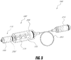
- a system 10 that includes a first component or bone cement injector 100 may extend into the cancellous bone of a vertebra, and a second component or cement activation component 105 which includes an emitter 110 for applying energy to bone cement.
- the first and second components 100 and 105 may include a flow passageway or channel 112 extending therethrough for delivering flowable bone cement into a bone.
- the bone cement injector component 100 and the cement activation component 105 can be integrated into a unitary device or can be de-mateable, as shown in FIG. 2 , by a mechanism such as a threaded portion 113 and a rotatable screw-on fitting 114.
- a source of bone cement in the form of a syringe-type body 115 is also coupleable to the system by use of a threaded fitting 116.
- the bone cement injector 100 may include a proximal end 118 and a distal end 120 with at least one flow outlet 122 therein to direct a flow of cement into a bone.
- the extension portion 124 of the injector 100 can be made of any suitable metal or plastic sleeve with flow channel 112 extending therethrough to the flow outlet 122.
- the flow outlet 122 may be present as a side port to direct cement flow transverse relative to the axis 125 of extension portion 124 or, alternatively, can be positioned at the distal termination of extension portion 124 in order to direct cement flows distally.
- the extension portion 124 can include first and second concentric sleeves that are positioned so as to be rotated relative to one another to align or misalign respective first and second flow outlets to allow selectively directed cements flow to be more or less axial relative to axis 125 of extension portion 124.
- second component 105 includes a handle portion that carries an emitter 110 for applying thermal energy to a cement flow within the flow channel 112 that extends through the emitter 110.
- the emitter 110 may apply thermal energy to bone cement 130 delivered from chamber 132 of source 115 to flow through the emitter 110 to therein to cause the viscosity of the cement to increase to a selected, higher viscosity value as the cement exits the injector flow outlet 122 into bone.
- the controlled application of energy to bone cement 130 may enable the physician to select a setting rate for the cement to reach a selected polymerization endpoint as the cement is being introduced into the vertebra, thus allowing a high viscosity that will be prevent unwanted cement extravasation.
- the thermal energy emitter 110 may be coupled to an electrical source 140 and controller 145 by an electrical connector 146 and a cable 148.
- electrical leads 149a and 149b may be coupled with connector 146 and extend to the emitter 110.
- one thermal energy emitter 110 has a wall portion 150 that includes a polymeric positive temperature coefficient of resistance (PTCR) material with spaced apart interlaced surface electrodes 155A and 155B as described in co-pending Provisional Application No. 60/907,469 filed April 3, 2007 titled Bone Treatment Systems and Methods (Atty Ref: DFINE.037PR).
- PTCR polymeric positive temperature coefficient of resistance
- FIG. 3 is a schematic representation of thermal energy emitter 110 which can have any elongated or truncated shape or geometry, tapered or non-tapered form, or include the wall of a collapsible thin-wall element.
- the positive (+) and negative (-) polarity electrodes 155A and 155B can have any spaced apart arrangement, for example radially spaced apart, helically spaced apart, axially spaced apart or any combination thereof.
- This resistively heated PTCR material of the emitter 110 may further generate a signal that indicates flow rate as described in Provisional Application No.
- 60/907,469 which in turn can be utilized by controller 145 to modulate energy applied to the bone cement therein, and/or modulate the flow rate of cement 130, which can be driven by a motor or stored energy mechanism.
- the emitter can be any non-PTCR resistive heater such as a resistive coil heater.
- the thermal energy emitter 110 can include a PTCR constant temperature heater as described above or may include one or more of a resistive heater, a fiber optic emitter, a light channel, an ultrasound transducer, an electrode and an antenna. Accordingly in any such emitter, the energy source 140 can include at least one of a voltage source, a radiofrequency source, an electromagnetic energy source, a non-coherent light source, a laser source, an LED source, a microwave source, a magnetic source and an ultrasound source that is operatively coupled to the emitter 110.
- a pressure mechanism 190 is coupleable to the bone cement source or syringe 115 for driving the bone cement 130 through the system 10.
- the pressure 190 can include any suitable manual drive system or an automated drive system such as any pump, screw drive, pneumatic drive, hydraulic drive, cable drive or the like.
- Such automated drive systems may be coupled to controller 145 to modulate the flow rate of cement through the system.
- the system 10 may further include a hydraulic system 162 with a fitting 163 that may detachably couple to fitting 164 of the bone cement source 115.
- the bone cement source 115 may include a syringe body with cement-carrying bore or chamber 165 that carries a prepolymerized, partially polymerized, or recently-mixed bone cement 130 therein.
- the hydraulic system 162 may further include a rigid plunger or actuator member 175 with o-ring or rubber head 176 that may move in chamber 165 so as to push the cement 130 through the syringe chamber 165 and the flow channel 112 in the system 100.
- a force application and amplification component 180 of the hydraulic system 162 may be reversibly couple to the bone cement source 115, where the force application and amplification component 180 includes a body 182 with pressurizable bore or chamber 185 therein that slidably receives the proximal end 186 of the actuator member 175.
- the proximal end 186 of actuator member 175 may include an o-ring or gasket 187 so that the bore 185 can be pressurized with flow media 188 by the pressure source 190 in order to drive the actuator member 170 distally to thereby displace bone cement 130 from the chamber 132 in the cement source or syringe 115.
- the surface area of an interface 200 between the actuator member 175 and pressurized flow media 188 may be larger than the surface area of an interface 200' between the actuator member 175 and the bone cement 130 so as to thereby provide pressure amplification between the pressurizable chamber 185 and chamber 132 of the cement source or syringe.
- the surface area of interface 200 may be at least about 150% of the surface area of interface 200', at least about 200% of the surface area of interface 200', at least about 250% of the surface area of interface 200' and at least about 300% of the surface area of interface 200'.
- the force application and amplification component 188 may be employed in the following manner.
- a bone fill material injector with a displaceable, non-fluid actuator component intermediate a first fluid chamber and a second cement or fill-carrying chamber may be provided.
- a flow of flow media may be provided into the first fluid chamber at a first pressure to thereby displace the actuator component to impinge on and eject bone cement or fill at a higher second pressure from the second chamber into a vertebra.
- a second pressure may be provided in the cement-carrying chamber 165 that is greater than the first pressure in the pressurizable chamber.
- the second pressure may be at least about 50% higher than the first pressure in the pressurizable chamber 185.
- the second pressure may be at least about 75% higher that the first pressure in the pressurizable chamber 185.
- the second pressure may be at least about 100% higher that the first pressure in the pressurizable chamber 185.
- the second pressure may be at least about 200% higher that the first pressure in the pressurizable chamber 185.
- the second pressure may be at least about 300% higher that the first pressure in the pressurizable chamber 185.
- one pressurizing mechanism for providing pressure to the force application and amplification component 180 may include a pneumatic or hydraulic line 205 that extends to pressure mechanism 190, such as a syringe pump 210, which is manually driven or motor-driven as is known in the art.
- pressure mechanism 190 such as a syringe pump 210
- the syringe pump 210 may be driven by an electric motor 211 operatively coupled to controller 145 to allow modulation of the pressure or driving force in combination with the control of energy delivery by emitter 110 from energy source 140.
- the pressurizing mechanism or pressure source 210 can include any type of mechanism or pump known in the art to actuate the actuator member 175 to move the bone cement in chamber 165.
- a suitable mechanism can include a piezoelectric element for pumping fluid, an ultrasonic pump element, a compressed air system for creating pressure, a compressed gas cartridge for creating pressure, an electromagnetic pump for creating pressure, an air-hammer system for creating pressure, a mechanism for capturing forces from a phase change in a fluid media, a spring mechanism that may releaseably store energy, a spring mechanism and a ratchet, a fluid flow system and a valve, a screw pump, a peristaltic pump, a diaphragm pump, rotodynamic pumps, positive displacement pumps, and combinations thereof.
- a remote switch 212 for actuating the pressure mechanism 190.
- a cable 214 extends from the controller 145 so that the physician can stand outside of the radiation field created by any imaging system used while treating a vertebra or other bone treatment site.
- the switch 212 can be wirelessly connected to the system as is known in the art.
- the elongated cable 214 and switch 212 can be directly coupled to the injector 100 or other component of the system 10.
- FIGS. 7 , 8A and 8B the figures illustrate certain methods of the present disclosure where the controlled application of energy to a bone cement 130 provides a bone cement with a controlled, on-demand increased viscosity and a controlled set time compared to prior art bone cements.
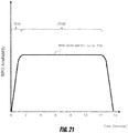
- FIG. 7 depicts a prior art bone cement known in the art, such as a PMMA bone cement, that has a time-viscosity curve 240 where the cement substantially hardens or cures within about 8 to 10 minutes post-mixing.
- the time point zero indicates the time at which the mixing of bone cement precursors, such as monomer and polymer components, is approximately completed.
- time-viscosity curve 240 for the prior art bone cement of FIG. 7 the cement increases in viscosity from about 500 Pa•s to about 750 Pa•s from time zero to about 6 minutes post-mixing. Thereafter, the viscosity of the prior art bone cement increases very rapidly over the time interval from about 6 minutes to 8 minutes post-mixing to a viscosity greater than 4000 Pa•s.
- a prior art bone cement having the time-viscosity curve of FIG. 7 may be considered to have a fairly high viscosity for injection in the range of about 500 Pa•s. At this viscosity range, however, the bone cement can still have flow characteristics that result in extravasation.
- the curing reaction of the bone cement involves an exothermic chemical reaction that initiates a polymerization process that is dictated, at least in part, by the composition of the bone cement precursors, such as one or more of a PMMA polymer, monomer, and initiator.
- FIG. 7 indicates the exothermic curing reaction over time as a gradation, where, the lighter gradation region indicates a lesser degree of chemical reaction and heat and the darker gradation region indicates a greater degree of chemical reaction and heat leading to more rapid polymerization of the bone cement precursors.
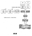
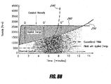
- FIG. 8A the block diagram illustrates a method of utilizing applied energy and an energy-delivery algorithm to accelerate the polymerization of a PMMA bone cement to provide a selected time-viscosity curve as shown in FIG. 8B .
- the time-viscosity curve 250 of a bone cement can have an initial viscosity is in the range of about 750 Pa•s at about time zero post-mixing and thereafter the viscosity increases in a more linear manner over about 10 to 14 minutes post-mixing than prior art bone cements.
- This bone cement may include a PMMA cement composition that provides a time-viscosity curve as in FIGS. 7 and 8B , as described in U.S.
- the bone cement 130 or more particularly, the mixing of the cement precursors includes a first curing reaction source for curing the bone cement as described above and results in the predetermined exothermic curing reaction post-mixing that is indicated by the gradations of reaction under the time-viscosity curve 250.
- the chart illustrates the PMMA bone cement with time-viscosity curve 250 together with the modified time-viscosity curve 260.
- the modified time-viscosity curve may be provided by the application of energy employing the system 10 of the present disclosure, as depicted in FIGS. 1 and 4-6 .
- FIG. 8B illustrates where the bone cement 130 undergoes a curing process (i.e., the time-viscosity curve 250) owing to self-heating of the composition as components of the bone cement composition react with each other.
- This curing process may be further influenced by the applied energy from energy source 140, controller 145 and emitter 110 to provide the modified time-viscosity curve 260 for cement injection into a bone in order to prevent extravasation.
- the modulation of applied energy over time from the second curing source or emitter 110 can be provided to complement the thermal energy generated by the exothermic reaction of the bone cement components in order to provide a substantially constant cement viscosity over a selected working time.
- This aspect of the present disclosure allows, for the first time, the provision of bone cements having a controlled, and substantially constant, viscosity that is selected so as to inhibit extravasation.
- the bone cement 130 and system 10 of the present disclosure are therefore notable in that a typical treatment of a vertebral compression fracture requires cement injection over a period of several minutes, for example from about 2 to 10 minutes or about 2 to 6 minutes, or about 2 to 4 minutes.
- the physician typically injects a small amount of bone cement, for example, about 1 of 2 cc's, then pauses cement injection for the purpose of imaging the injected cement to check for extravasation, then injecting additional cement and then imaging, etc.
- the steps of injection and imaging may be repeated from about 2 to 10 times or more, where the complete treatment interval can take about 4 to 6 minutes or more.
- a cement with a working time of at least about 5-6 minutes is needed for a typical treatment of a VCF, otherwise the first batch of cement may be too advanced in the curing process (see FIG. 7 ) and a second batch of cement may need to be mixed.
- the cement viscosity can be approximately constant, thus providing a very long working time of about 8-10 minutes.
- the bone cement system includes: a first energy source and a second energy source, different from one another, that facilitate a curing reaction occurring within a bone cement.
- the first energy source includes heat generated by an exothermic curing reaction resulting from mixture of bone cement precursor components.
- the second energy source includes thermal energy introduced into the bone cement by a thermal energy emitter 110 that may provide a selected amount of energy to the bone cement.
- the system further includes a controller 145 that may modulate the thermal energy provided to the bone cement composition by the thermal energy emitter 110. In this manner, the curing reaction of the bone cement composition may be controlled over a selected working time. It can be understood from U.S. Provisional Application Number 60/899,487 and U.S. Application No. 12/024,969 , that PMMA cement compositions can be created to provide highly-extended working times.
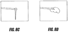
- FIGS. 8C and 8D are images of a PMMA bone cement exiting an injector without applied energy and the same PMMA bone cement exiting an injector as modified by applied energy according to one energy-delivery algorithm.
- the bone cement emerging from the injector without the benefit of applied energy is of relatively low viscosity, as evidenced by the ease with which the bone cement is deformed by the force of gravity.
- Such behavior indicates the bone cement of FIG. 8C may be prone to extravasation.
- the bone cement modified by applied energy of high viscosity as evidenced by its accumulation about the end of the injector.
- Such behavior indicates that the bone cement of FIG. 8D is not prone to extravasation.
- the controller 145 may also allow the physician to select an energy-delivery algorithm in the controller 145 to increase and decrease the cement viscosity as the cement exits the injector following the application of energy to the cement flow.
- an energy-delivery algorithm in the controller 145 to increase and decrease the cement viscosity as the cement exits the injector following the application of energy to the cement flow.
- such algorithms may provide substantially automated control of the application of energy to the composition by the system 10.
- a bone treatment system 10 may be provided that employs algorithms for modulating energy applied to the bone cement system 130.
- the bone treatment system 130 may include a bone cement injector system, a thermal energy emitter 110 that may deliver energy to a flow of bone cement through the injector system, and a controller.
- the controller 145 may include hardware and/or software for implementing one or more algorithms for modulating applied energy from the emitter 110 to a bone cement flow.
- the energy-delivery algorithms may be further employed to increase the applied energy from about zero to a selected value at a rate that inhibits vaporization of at least a portion of a monomer portion of the bone cement 130.
- the controller 145 may enable a physician to select a bone cement viscosity using a selector mechanism operatively connected to the controller 145.
- the selector mechanism may cause the controller 145 to initiate one or more of the energy-delivery algorithms.
- the physician can select among a plurality of substantially constant viscosities that can be delivered over the working time. Examples of ranges of such viscosities may include less than about 1,000 Pa•s and greater than about 1,500 Pa•s.
- each selection being a viscosity range useful for a particular purpose, such as about 1,000 Pa•s for treating more dense bone when extravasation is of a lesser concern, or between about 4,000 Pa•s and 6,000 Pa•s in a treatment of a vertebral fracture to prevent extravasation and to apply forces to vertebral endplates to reduce the fracture.
- the system 10 may further include a temperature sensor 272 that is disposed in a mixing device or assembly 275.
- the mixing assembly 275 may include any container that receives bone cement precursors for mixing before placement of the mixed cement in the bone cement source 115 (see FIG. 6 ).
- the temperature sensor 272 may be placed in the cement mixing assembly 275 because cement may be stored in a hospital in an environment having a lower or higher temperature than the operating room, which may affect the time-viscosity curve of the cement.
- the temperature sensor 272 can be operatively coupled to the controller 145 by a cable or a wireless transmitter system.
- the sensor 272 may be unitary with the mixing assembly 175 and disposable.
- the sensor 272 can be reusable and detachable from the mixing assembly 275.
- a temperature sensor 276 may be operatively connected to one or more packages 280 of the bone cement precursors to thereby indicate the actual temperature of the cement precursor(s) prior to mixing. Such a temperature sensor 276 may indicate the stored temperature and/or the length of time that such cement precursors have been in the operating room when compared to ambient room temperature measured by sensor 270 in the controller 145.
- This sensor 276 can include one or more temperature sensors that may include, but are not limited to, thermocouples, or thermochromic inks.
- the temperature sensors 276 may be further disposed on the surface of the bone cement package 280, allowing for visual identification of the temperature of the cement precursors.
- At least one temperature sensor 282 can be located in cement source 115 of the system and/or in a distal portion of the injector component 100 for monitoring cement temperature in a cement flow within the system 10.
- a bone treatment system may include a bone cement injector system 10 that includes a thermal energy emitter 110 that may deliver energy to a bone cement within the injector system, a controller 145 that may modulate applied energy from the emitter to control a curing reaction of the cement, and a sensor system operatively coupled to the injector system 100 for measuring an operational parameter of bone cement 130 within the system 10.
- a sensor of the sensor system may include a temperature sensor, indicated at 270, which is disposed in controller assembly 145.
- the temperature sensor 270 of the controller assembly 145 may allow for input of control algorithms into the system 10 for modulating applied energy from the emitter 110 that are dependent on ambient air temperature in the operating room environment.
- control algorithms may be of significant utility, as the ambient temperature of an operating room may affect the time-viscosity curve of an exothermic PMMA-based bone cement.
- the bone cement system 10, and more particularly, the cement mixing assembly 275 of FIG. 6 may include a sensor, switch, or indication mechanism 285 for indicating an approximate time of initiation of bone cement mixing.
- a sensor or indication mechanism 285 can include any manually-actuated mechanism coupled to the controller 145, a mechanism that senses the disposition of the cement precursors in the mixing assembly or the actuation of any moveable mixing component of the assembly, and combinations thereof.
- the system 10 and controller 145 may, in this manner, provide one or more of visual, aural, and/or tactile signals indicating that a selected mixing time interval has been reached.
- This signal may enable consistent measurement of the time at which mixing of the bone cement is completed, also referred to as the zero post-mixing time, such that the viscosity at this time may be similar in all cases.
- energy may be properly applied as described above.
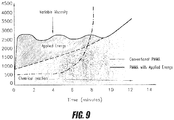
- the system 10 also can include a sensor, switch or indication mechanism 288 that indicates the termination of bone cement mixing, and thus time zero on a time-viscosity curve as in FIG. 9 , which may be used for setting the algorithms in the controller 145 for controlling applied energy and the cement flow rate.
- the bone cement system 10 may include a sensor that measures and indicates the bone cement flow rate within the flow passageway in the injector system 100.
- the motor drive system 211 may drive the cement via the hydraulic system 162 at a substantially constant rate through the injector and emitter 110.
- a sensor 290 may be operatively coupled to the motor drive which can measure the force being applied by the drive to the cause the desired cement flow through the system 10, which can in turn be used to sense any tendency for a slow-down in the desired flow rate, for example due to an unanticipated increase in viscosity of the bone cement in the system 10.
- the controller 145 can increase the flow rate or decrease the applied energy from emitter 110 to allow a selected cement viscosity and flow rate from the injector 100 into bone to be maintained.
- Such bone cements 130 in combination with the system 10 of the present disclosure, may thus allow for selected working times.
- working times may include, but are not limited to, at least about 6 minutes, at least about 8 minutes, at least about 10 minutes, at least about 12 minutes, at least about 14 minutes, at least about 16 minutes, at least about 18 minutes, at least about 20 minutes, and at least about 25 minutes.
- the bone treatment system may include: a first and second energy source for causing a controlled curing reaction in a bone cement.
- the first source may include an exothermic curing reaction which occurs in response to mixing cement precursor components.
- the second source may include a thermal energy emitter capable of applying energy to the bone cement in order to vary an exothermic curing reaction of the bone cement.
- the system may further include a controller capable of modulating the applied energy from the emitter to thereby control the exothermic curing reaction over a selected working time.
- the controller may be capable of modulating applied energy to provide a selected bone cement viscosity over a working time of at least about 2 minutes, at least about 4 minutes, at least about 6 minutes, at least about 8 minutes, at least about 10 minutes, at least about 12 minutes, at least about 14 minutes, at least about 16 minutes, at least about 18 minutes, at least about 20 minutes, and at least about 25 minutes.
- the control system 10 may allow for application of energy to a bone cement so as to provide a bone cement that possesses a selected cement viscosity range as it exits the injector outlet 122 over the selected working time.
- the selected viscosity range may include, but is not limited to, about 600 Pa•s, about 800 Pa•s, about 1000 Pa•s, about 1200 Pa•s, about 1400 Pa•s, about 1600 Pa•s, about 1800 Pa•s, about 2000 Pa•s, about 2500 Pa•s, about 3000 Pa•s and about 4000 Pa•s.
- a method of preparing a curable bone cement for injection into a vertebra can include: mixing bone cement precursors so as to enable a curing reaction to take place in the bone cement and applying energy to the bone cement from an external source so as to provide energy to the bone cement.
- the energy applied from the external source may be controlled by a controller in combination with the curing reaction so as to provide a selected cement viscosity.
- the method may further include varying the amount of energy applied from the external source in response to a selected length of a post-mixing interval.
- the method may include varying the amount of applied energy from the external source in response to ambient temperature that is measured by a temperature sensor in the system.
- the method may include varying the applied energy from the external source in response to a selected injection rate of the bone cement flow through the system 10.
- the method may include varying the applied energy from the external source so as to provide a bone cement having an injection viscosity of at least about 500 Pa•s, at least about 1000 Pa•s, at least about 1500 Pa•s, at least about 2000 Pa•s, at least about 3000 Pa•s and at least about 4000 Pa•s.
- the control system may allow for application of energy to a bone cement so as to provide a bone cement that possesses a substantially constant cement viscosity over the selected working time.
- the control system 10 may allow for the application of energy to a bone cement so as to provide a bone cement that possesses a plurality of selected time-viscosity profiles of the cement as it exits the injector 100.
- the controller 145 and energy emitter 110 may be capable of applying energy to the bone cement in an amount that is sufficient to very rapidly increase the viscosity of the bone cement to a selected viscosity that will inhibit extravasation.
- the system 10 and the bone cement 130 discussed herein may be employed to provide a bone cement whose viscosity can be elevated to above about 2000 Pa•s within about 15-30 seconds.
- the method of bone cement treatment may include utilizing an energy emitter 110 that applies energy to bone cement to controllably increase its viscosity to at least 200 Pa•s, at least 500 Pa•s or at least 1,000 Pa•s in less than 2 minutes or less than 1 minute.
- a method of bone cement treatment may include utilizing an energy emitter that applies energy to bone cement to controllably increase the viscosity to at least 1,000 Pa•s, at least 1,500 Pa•s, at least 2,000 Pa•s or at least 2,500 Pa•s in less than 2 minutes or less than 1 minute.
- a method of preparing a curable bone cement for injection into a vertebra allows a bone cement to exhibit a selected time-viscosity profile.
- the method may include: mixing bone cement precursors so as to cause a curing reaction characterized by a first time-viscosity profile of the bone cement, actuating an energy controller so as to controllably apply energy to the bone cement from an external energy source so as to cause the bone cement to adopt a second time-viscosity profile, different from the first time-viscosity profile, and injecting the cement characterized by the cement second time-viscosity profile into the vertebra.
- the cement viscosity may be at least about 500 Pa•s, at least about 1000 Pa•s, at least about 1500 Pa•s, at least about 2000 Pa•s, at least about 3000 Pa•s, or at least about 4000 Pa•s.
- the method may further include actuating the controller to modulate applied energy in response to control signals including, but not limited to, the length of a cement post-mixing interval, the ambient temperature, the bone cement temperature, and rate of bone cement injection into the vertebra.
- FIG. 10 provides a schematic, graphical representation of the time-viscosity response, 250 and 255, respectively, of the bone cement of FIG. 8A after mixing at ambient temperatures of about 22°C. and 18°C. It can be seen that different levels of energy may be applied to achieve a similar time-viscosity curve 260 of FIG. 10 . For example, less energy may be applied to bone cement at about 22°C than is applied to the bone cement at about 18°C in order to achieve the time-viscosity response 160, as the higher temperature bone cement, prior to energy application, contains more energy than lower temperature bone cement.
- a method of the present disclosure may include providing inputs for the control algorithms for controlling applied energy to cement flows that factor in ambient temperatures.
- the system 10 may be employed in order to provide the bone cement 130 with a working time for polymerizing from an initial state to a selected endpoint of at least about 10 minutes, at least about 12 minutes, at least about 14 minutes, at least about 16 minutes, at least about 18 minutes, at least about 20 minutes, at least about 25 minutes, at least about 30 minutes and at least about 40 minutes, as disclosed in U.S. Provisional Application No. 60/899,487 .
- the initial state may include a first selected viscosity range of the bone cement 130 within about 90 to 600 seconds after completion of mixing of the bone cement components.
- the selected endpoint of the bone cement 130 may include a second selected viscosity range that substantially inhibits bone cement extravasation.
- the terms "polymerization rate" and "working time” may be used alternatively to describe aspects of the time interval over which the cement polymerizes from the initial state to the selected endpoint.
- the energy source 140 may also be capable of applying energy to the bone cement 130 via the emitter 110 and accelerating a polymerization rate of the bone cement 130 by at least about 20%, at least about 30%, at least about 40%, at least about 50%, at least about 60%, at least about 70%, at least about 80%, at least about 90% and at least about 95%, as compared to the polymerization rate achieved absent this application of energy.
- the energy source 140 and controller 145 may be capable of accelerating the polymerization rate of the bone cement 130 to the selected endpoint in less than about 1 second, less than about 5 seconds, less than about 10 seconds, less than about 20 seconds, less than about 30 seconds, less than about 45 seconds, less than about 60 seconds and less than about 2 minutes.
- a method of using the system 10 of FIGS. 1-6 to treat a vertebra includes a first operation of introducing a cement injector needle into a vertebra.
- the needle may include a flow channel extending from a proximal injector end to a distal injector end possessing a flow outlet.
- the method may further include a second operation of causing a flow of bone cement from a bone cement source through a flow channel in an energy-delivery component and the injector needle.
- the method may additionally include applying energy from the energy-delivery component to the flow of bone cement so as to cause a change in the setting rate of the cement so as to reach a selected polymerization endpoint.
- the applied energy may accelerate setting of a bone cement before it exits the flow outlet of the injector.
- the method and the selected polymerization endpoint may further provide a bone cement that exhibits a viscosity that substantially prevents cement extravasation following introduction into the vertebra.
- the bone cement system 400 may include a first and a second thermal energy emitter for controlled application of energy to a bone cement flow within the flow passageway 112 of the injector system 100. More particularly, first emitter 110 may be disposed in the first handle component 105 as described previously. A second emitter 410 may be disposed in a medial or distal portion of the second extension component 110 of the injector system 100. The controller 145 may be capable of modulating applied energy from the first and second emitters, 110 and 410, to provide a controlled curing reaction of the flow of bone cement 130.
- the first emitter 110 can apply energy to warm the flow of cement 130 to accelerate it polymerization so that the selected flow rate carries the cement 130 to the location of the second emitter 410 at a viscosity of less than about 500 to 1000 Pa•s and, thereafter, the applied energy of the second emitter 410 may increase the viscosity of the bone cement 130 to greater than about 2000 Pa•s.
- the bone cement viscosity within the flow channel 112 can be kept at a level that can be pushed with a low level of pressure and the final viscosity of the cement 130 exiting the outlet 122 can be at a relatively high viscosity, for example, at a level capable of fracturing cancellous bone, such as greater than about 2000 Pa•s.
- FIG. 11 further illustrates that electrical connector components 414a and 414b may be provided in the interface between the first and second components, 100 and 105, in order to provide an electrical connection from electrical source 140 to the emitter 410 via electrical wires indicated at 416 in the handle portion 105 of the system.
- the second emitter 410 can include a PTCR emitter, as described previously, or any other type of heating element.
- the heating element can have any length that includes the entire length of the extension portion 124.
- the emitter 110 in handle component 105 has a length of less than about 50 mm and can carry a volume of cement that is less than about 1.0 cc, less than about 0.8 cc, less than about 0.6 cc, less than about 0.4 and less than about 0.2 cc.
- the energy-delivery emitter 110 may be actuated by the operator from a location outside any imaging field.
- the cable carrying an actuation switch 212 can be any suitable length, for example about 10 to 15 feet in length (see FIG. 6 ).
- the energy-delivery emitter 110 may be actuated to apply energy of at least about 0.01 Watt, at least about 0.05 Watt, at least about 0.10 Watt, at least about 0.50 Watt and at least about 1.0 Watt.
- the applied energy may be modulated by controller 145.
- the energy source 140 and controller 145 may be capable of accelerating the polymerization rate of the bone cement 130 to the selected endpoint in less than 1 second, 5 seconds, 10 seconds, 20 seconds, 30 seconds, 45 seconds, 60 seconds and 2 minutes.
- the energy source 140 and controller 145 may be capable of applying energy to a bone cement composition 130 for accelerating the polymerization rate of the bone cement 130 by at least about 20%, at least about 30%, at least about 40%, at least about 50%, at least about 60%, at least about 70%, at least about 80%, at least about 90% and at least about 95%, as compared to the polymerization rate absent the applied energy.
- a method of bone cement injection includes modulating a rate of bone cement flow in response to a determination of a selected parameter of the cement flow.
- Examples of the selected parameter may include the flow rate of the bone cement.
- the method of bone cement injection may further include applying thermal energy to the bone cement and modulating the thermal energy application from an emitter in the injector body to the cement flow.
- the method of bone cement injection may further include modulating the application of energy in response to signals that relate to a selected parameter, such as the flow rate of the cement flow.
- a method of bone cement injection includes (a) providing a bone cement injector body carrying a PTCR (positive temperature coefficient of resistance) material in a flow channel therein, (b) applying a selected level of energy to a bone cement flow traveling through the PTCR material, and (c) utilizing an algorithm that processes impedance values of the PTCR material in order to determine the bone cement flow rate.
- the method of bone cement injection may further include modulating a cement injection parameter in response to the processed impedance values. Examples of the cement injection parameter may include, but are not limited to flow rate, pressure, and power applied to the flow.
- a further method of bone cement injection may include: (a) providing a bone cement injector body carrying a PTCR material or other thermal energy emitter in a flow channel therein, (b) causing a bone cement to flow through the flow channel at a selected cement flow rate by application of a selected level of energy delivery to the cement flow through the emitter, and (c) modulating the selected flow rate and/or energy delivery to maintain a substantially constant impedance value of the emitter material over a cement injection interval.
- the selected cement injection interval can include at least about 1 minute, at least about 5 minutes, at least about 10 minutes, and at least about 15 minutes.
- the method may modulate the selected flow rate and/or energy delivery to maintain a substantially constant viscosity of bone cement ejected from the injector over a selected cement injection time interval.
- the time interval may include from about 1 minute to 10 minutes.
- the system and energy source may be capable of applying energy of at least 0.01 Watt, 0.05 Watt, 0.10 Watt, 0.50 Watt and 1.0 Watt.
- the energy source 140 and controller 145 may be capable of accelerating the polymerization rate of the bone cement to a selected endpoint in less than about 1 second, less than about 5 seconds, less than about 10 seconds, less than about 20 seconds, less than about 30 seconds, less than about 45 seconds, less than about 60 seconds and less than about 2 minutes.
- a method of bone cement injection may utilize embodiments of the systems 10 and 400 as described above. Such methods may include(a) providing a bone cement injector body with a flow channel extending therethrough from a proximal handle end though a medial portion to a distal end portion having a flow outlet, (b) causing cement flow through the flow channel, and (c) warming the cement flow with an energy emitter in a proximal end or medial portion thereof to initiate or accelerate polymerization of the cement of the cement flow.
- the method may further include providing a flow rate of the cement flow that ranges from about 0.1 cc/minute to 20 cc/minute, from about 0.2 cc/minute to 10 cc/minute and from about 0.5 cc/minute to 5 cc/minute.
- the above-described method of bone cement injection may further provide a selected cement flow rate to provide a selected interval in which the cement flows are allowed to polymerize in the flow channel downstream from the energy emitter.
- This method may include providing a selected interval of greater than about 1 second, greater than about 5 seconds, greater than about 10 seconds, greater than about 20 seconds, and greater than about 60 seconds.
- the above-described method may also utilize an energy emitter that applies energy sufficient to elevate the temperature of the bone cement 130 by at least about 1°C, at least about 2°C, and at least about 5°C.
- the method of bone cement injection may additionally include utilizing an energy emitter that applies at least about 0.1 Watts of energy to the cement flow, at least about 0.5 Watts of energy to the cement flow, and at least about 1.0 Watts of energy to the cement flow.
- the method may include adjustment of the flow rate of the bone cement flow in intervals by controller 145, or being continuously adjusted by a controller 145.
- the bone cement injection system of FIGS. 1-11 may utilize a controller 145 and algorithms for applying energy to bone cement flows to allow the bone cement 130 exiting the injector to possess a selected temperature that is higher than the ambient temperature of the injector. This ability reflects the fact that polymerization has been accelerated, thus reducing the amount of total heat released into bone. More particularly, the method may include injecting a settable bone cement into a bone after mixing a first component and a second component of the bone cement, thereby initiating a chemical reaction to initiate setting of the bone cement, accelerating the polymerization with applied energy from an external source, and ejecting the bone cement from an injector portion positioned in bone.
- the bone cement upon ejection, may possess a temperature greater than the temperature ambient the injector.
- the method can further include ejecting the bone cement from a terminal portion of an injector positioned in bone at a temperature of at least about 28°C, at least about 30°C, at least about 32°C, at least about 34°C, at least about 36°C, at least about 38°C, at least about 40°C, at least about 42°C, at least about 44°C, at least about 46°C, at least about 48°C, at least about 50°C, at least about 52°C, at least about 54°C, at least about 56°C, at least about 58°C, at least about 60°C, at least about 62°C, at least about 64°C, at least about 66°C, at least about 68°C, at least about 70°C, at least about 72°C, at least about 74°C, at least about 76°C, at least about 78°C, and at least about 80°C.
- a method of injecting a bone cement into bone includes mixing first and second bone cement components, thereby causing an exothermic chemical reaction which results in a thermal energy release.
- the method may further include actuating an injector control system capable of controlling the temperature of the bone cement before the bone cement contacts bone.
- the actuating step can include (i) controlling the flow rate of the bone cement within a flow passageway of an injector system, (ii) controlling the application of energy to the bone cement from an emitter operatively coupled to an energy source, and (iii) controlling the driving force applied to the flow of bone cement which may benefit from adjustment based on the bone cement viscosity.
- the actuating step can also include sensing an operating parameter of the bone cement flow to which the controller is responsive.
- the operating parameter can include the bone cement flow rate, the bone cement temperature, the driving force applied to the cement flow, the energy applied to the cement from an emitter coupled to an energy source and cement viscosity and environmental conditions, such as temperature and humidity in the environment ambient to the injector system.
- the controller 145 can be capable of modulating the flow rate, modulating the applied energy, and/or modulating the driving force in response to sensing any one or more of the above operating parameters.
- the method includes mixing a first and a second bone cement components so as to cause an exothermic chemical reaction that results in a thermal energy release.
- the method also includes actuating an injector control system which is capable of controlling an amount of thermal energy released from the cement before the bone cement contacts bone tissue to thereby reduce the thermal energy released into the bone.
- the thermal energy released from the cement may be directly related to the level of polymerization acceleration from the applied energy, as well as the dwell time of the cement within the flow channel before the cement exits the outlet in a terminal portion of the injector.
- the dwell time of the cement in the flow channel can be controlled by controller 145 as described above, where at least one of the flow rate and driving force applied to the cement flow can be modulated.
- the application of energy by emitter 110 in component 105 provides for a dwell time within the flow channel 112 before exiting outlet 122 for a flow interval of at least about 5 seconds, at least about 10 seconds, at least about 20 seconds, at least about 30 seconds, at least about 40 seconds and at least about 60 seconds.
- This method of conditioning and injecting bone cement can allow a thermal energy release from the bone cement before the bone cement contacts bone of at least about 10%, at least about 15%, at least about 20%, at least about 25%, at least about 30%, at least about 35%, at least about 40%, at least about 45% and at least about 50% of the total thermal energy released during curing of the bone cement composition.
- a method of injecting a bone cement controls the amount of thermal energy released by the bone cement before the bone cement contacts bone tissue.
- the method includes controlling an injector control system that is capable of controlling the rate of chemical reaction before the bone cement contacts bone tissue.
- the reaction rate can be adjusted by the controller such that the maximum composition temperature is reached when the cement is within the flow channel of the injector system, prior to reaching the bone tissue.
- the amount of total thermal energy released by the bone cement is released while the bone cement is still within the flow channel of the injector system, before the bone cement contacts the bone tissue. This method substantially reduces the amount of thermal energy which is released by the bone cement into the bone tissue.
- Another method of injecting bone cement includes an actuating step that can include allowing at least about 10% of the total thermal energy released from a bone cement to be released while the bone cement flows within the injector system. Such energy release may be accomplished by providing a mean cement flow rate of at least about 0.1 cc/min, at least about 0.5 cc/min, at least about 1.0 cc/min, at least about 1.5 cc/min, at least about 2.0 cc/min and at least about 2.5 cc/min during heating within the bone cement injector. The method may further include maintaining the bone cement within the cannula for at least about 20 seconds after being heated.
- the actuating step can allow at least about 10% of the total thermal energy released from a bone cement to flow over a flow distance within the flow channel 112 of the injector system, of least 5 mm, at least 10 mm, at least about 20 mm, at least about 30 mm, at least about 40 mm, at least about 50 mm, at least about 60 mm, at least about 70 mm, at least about 80 mm, at least about 90 mm and at least about 100 mm.
- a selected amount of thermal energy from the exothermic reaction of the bone cement components may be released within the flow channel so as to inhibit a selected portion of the thermal energy from reaching a patient's bones.
- the method can include selecting first and second bone cement components, or precursors, that result in a peak temperature of the bone cement composition during curing of less than about 75°C, less than about 70°C, less than about 65°C, and less than about 60°C.
- Such bone cements may include those bone cements described herein.
- a bone cement injection system of the present disclosure includes first and second bone cement components, or precursors, that, upon mixing, result in a chemical reaction that sets the cement mixture.
- the bone cement injection system further includes an injector system that may include a drive system for inducing the cement mixture to flow through the system and into bone.
- the bone cement injection system may further include an energy emitter for applying energy to the cement mixture in the injector system to thereby accelerate the chemical reaction between the first and second bone cement components therein.
- the bone cement injection system may also include a controller, operatively coupled to at least one of the drive system and energy emitter, for controlling the acceleration of the chemical reaction in the bone cement.
- the first and second bone cement components, or precursors may possess a post-mixing peak temperature of less than about 75°C, less than about 70°C, less than about 65°C and less than about 60°C.
- the drive system and the controller may further be capable of controllably applying a driving force to the cement mixture in the injector system of at least about 3447 Kpa (500 psi), at least about 6895 Kpa (1,000 psi), at least about 10,342 Kpa (1,500 psi), at least about 13,789 Kpa (2,000 psi), at least about 17,236 Kpa (2,500 psi, at least about 20,684 Kpa (3,000 psi), at least about 24,132 KPa (3,500 psi), at least about 27,579 Kpa (4,000 psi), at least about 31,026 Kpa (4,500 psi) and at least about 34473 Kpa (5,000 psi).
- the drive system and controller may be capable of controllably maintaining a substantially constant flow rate of the cement mixture.
- Examples of the flow rate control may include, but are not limited to, flow rate variations that are within less than about 1% variation; less than about 5% variation; less than about 10% variation and less than about 15% variation.
- the drive system and controller may be capable of controlling a mean cement mixture flow rate.
- the mean cement flow rate may include at least about 0.1 cc/min, at least about 0.5 cc/min, at least about 1.0 cc/min, at least about 1.5 cc/min, at least about 2.0 cc/min and at least about 2.5 cc/min.
- the energy emitter and controller may further be capable of controllably applying energy to the cement mixture.
- the controller may provide at least about 20 joules/cc, at least about 40 joules/cc, at least about 60 joules/cc, at least about 80 joules/cc, at least about 100 joules/cc, at least about 120 joules/cc, at least about 140 joules/cc, at least about 160 joules/cc, and at least about 180 joules/cc of the bone cement.
- the bone cement injection system may include an energy emitter and controller capable of providing a dynamic or a preprogrammed adjustment of applied energy to the cement mixture in response to a signal indicative of the flow rate of the cement mixture.
- the signal may include a feedback signal to the controller 145 indicative of at least one of the temperature of the cement mixture, the viscosity of the cement mixture, the flow rate of the cement mixture and the driving force applied to the cement mixture, at least one environment condition, and combinations thereof.
- the present disclosure may relate to bone cement compositions and formulations for use in the bone cement delivery systems described above, such as systems 10 and 400.
- the bone cement formulations may provide extended working times, since the viscosity of the bone cement can be altered and increased on demand when injected.
- Bone cements such as polymethyl methacrylate (PMMA) have been used in orthopedic procedures for several decades, with initial use in the field of anchoring endoprostheses in a bone.
- skeletal joints such as in the hip are replaced with a prosthetic joint.
- the prosthetic joint may be cemented into the bone using an acrylic bone cement, such as PMMA.
- an acrylic bone cement such as PMMA.
- bone cements also have been widely used in vertebroplasty procedures where the cement is injected into a fractured vertebra to stabilize the fracture and eliminate micromotion that causes pain.
- a polymethyl methacrylate bone cement may be provided.
- the bone cement Prior to injection of the bone cement into a patient, the bone cement may include a powder component and a liquid monomer component.
- the powder component may include granules of methyl methacrylate or polymethyl methacrylate, an X-ray contrast agent and a radical initiator.
- barium sulfate or zirconium dioxide may be employed as an X-ray contrast agent.
- Benzoyl peroxide (BPO) may further be employed as radical initiator.
- the liquid monomer component may include a liquid methyl methacrylate (MMI), an activator, such as N,N-dimethyl-p-toluidine (DMPT), and a stabilizer, such as hydroquinone (HQ).
- DMPT N,N-dimethyl-p-toluidine
- HQ hydroquinone
- Typical bone cements formulations including PMMA formulations, used for vertebroplasty have a fairly rapid cement curing time after mixing of the powder and liquid components. This allows the physician to not waste time waiting for the cement to increase in viscosity prior to injection. Further, the higher viscosity cement is less prone to unwanted extravasation, which can cause serious complications.
- the disadvantage of such current formulations is that the working time of the cement, the time during which the cement is within a selected viscosity range that allows for reasonably low injection pressures while still being fairly viscous to help limit cement extravasation, is relatively short, for example, about 5 to 8 minutes.
- the viscosity of the bone cement during the working time may range between approximately 50 to 500 N s/m 2 and may be measured according to ASTM standard F451, "Standard Specification for Acrylic Bone Cement,".
- a bone cement of the present disclosure provides a formulation adapted for use with the cement injectors and energy delivery systems described above, such as systems 10 and 400.
- These formulations are distinct from conventional formulations and have greatly extended working times for use in vertebroplasty procedures with the viscosity control methods and apparatus disclosed herein and in co-pending applications listed above.
- the bone cement provides a formulation adapted for injection into a patient's body, where the setting time is about 25 minutes or more, more preferably about 30 minutes or more, more preferably about 35 minutes or more, and even more preferably about 40 minutes or more.
- Setting time is measured in accordance with ASTM standard F451.
- the bone cement of the present disclosure prior to mixing and setting, includes a powder component and a liquid component.
- the powder component may include a PMMA that is about 64% to 75% by weight based on overall weight of the powder component.
- an X-ray contrast medium may be further provided in a concentration less than about 50 wt. %, such as about 25 to 35 wt. %, and about 27% to 32 wt. % based on overall weight of the powder component.
- the X-ray contrast medium in one embodiment, may include barium sulfate (BaS04) or zirconium dioxide (Zr02).
- the formulation may further include BPO that is about 0.4% to 0.8% by weight based on overall weight of the powder component.
- the BPO is less than about 0.6 wt. %, less than about 0.4 wt. % and less than about 0.2 wt. % based on overall weight of the powder component.
- the liquid component may include MMA that is greater than about 99% by weight based on overall weight of the liquid component.
- the liquid component may also include DMPT that is less than about 1% by weight based on overall weight of the liquid component.
- the liquid component may also include hydroquinone that ranges between about 30 and 120 ppm of the liquid component.
- the liquid weight/powder weight ratio may be equal to or greater than about 0.4.
- the PMMA may includes particles having a mean diameter ranging from about 25 microns to 200 microns or ranging from about 50 microns to 100 microns.
- the concentrations of benzoyl peroxide and DMPT within embodiments of the bone cement composition may be varied in order to adjust setting times.
- Studies examining the influence of bone cement concentration on setting times ( FIG. 12 ) have demonstrated that, in bone cements comprising BPO and DMPT, increases in BPO and DMPT concentration increase the set time of the bone cement.
- the data further illustrate that, of the two bone cement constituents, BPO may exert a greater rate of effect on set time than does DMPT.
- the concentration of BPO, DMPT, and combinations thereof may be increased within the ranges discussed above so as to increase the setting time of the composition.
- the setting time of the cement may also be influenced by applying energy to the bone cement composition.
- the injector system of FIGS. 1-11 may be capable of delivering energy to the bone cement composition.
- the applied energy may heat the bone cement composition to a selected temperature.
- FIG. 13 illustrates temperature as a function of time from initial mixing for one embodiment of the bone composition so injected.
- the solid line of FIG. 13 represents the behavior of the bone cement composition when it is not heated by the injector system, referred to as condition 1. It is observed that, under condition 1, the composition exhibits three regimes.
- the first regime is low heating rate regime, where the temperature of the composition increases modestly with time. In this regime, the composition begins to slowly self-heat due the onset of a chemical reaction between at least a portion of its components.
- the second regime is a high heating rate regime, where the chemical reaction causes the composition temperature rises sharply.
- the composition enters a third, cooling regime, during which the temperature of the composition decreases back to room temperature.
- the dotted line of FIG. 13 represents the behavior of the composition when it is heated by the injector system, referred to as condition 2.
- condition 2 In contrast to condition 1, four regimes of behavior are exhibited by the composition under condition 2.
- the first, low heating rate regime, the second, high heating rate regime, and the third, cooling regime, are again observed.
- condition 1 a new, injector heating regime, is observed between the first and second regimes.
- This new regime exhibits a rapid increase in the composition temperature due to injector heating of the composition.
- the composition temperature is observed to peak and fall towards the end of the duration of this regime, the temperature does not fall back to the same level as observed under condition 1 at about the same time. Therefore, when the second, high heating rate regime is entered, the temperature of the composition under condition 2 is greater than that under condition 1 and the composition temperature rises to a peak temperature which is greater than that achieved under condition 1.
- the setting time of the compositions under conditions 1 and 2 can be measured according to ASTM standard F451 and compared to identify changes in setting time between the two conditions. It is observed that the setting time of the composition under condition 1 is approximately 38 minutes, while the setting time of the composition under condition 2 is approximately 28 minutes, a reduction of about 10 minutes. Thus, by heating the bone cement, the setting time of embodiments of the bone cement composition may be reduced.
- the setting time of the bone cement may be increased or decreased.
- the concentration of BPO and/or DMPT in the bone cement may be varied and the composition may be heated so as to adjust the setting time to a selected value.
- the setting time is selected to be about 25 minutes or more, more preferably about 30 minutes or more, more preferably about 35 minutes or more, and even more preferably about 40 minutes or more.
- Embodiments of the bone cement composition may further be heated using the injector system of FIGS. 1-11 in order to alter the viscosity of the composition.
- FIG. 14 illustrates measurements of viscosity as a function of time for an embodiment of the bone cement compositions heated to temperatures ranging between about 25°C to 55°C. It may be observed that the bone cement at the lowest temperature, about 25°C, exhibits the slowest rate of viscosity increase, while the bone cement at the highest temperature, about 55°C, exhibits the highest rate of viscosity increase. Furthermore, at intermediate temperatures, the bone cement exhibits intermediate rates of viscosity increase.
- the peak temperature of the bone cement composition is higher when the cement is heated by the injector system. Furthermore, by adjusting the energy output of the injector system, the temperature to which the bone cement rises may be varied. Thus, the injector system may be employed to deliver bone cements having selected levels of viscosity.
- a bone cement has a first component comprising greater than about 99 wt. % methyl methacrylate (MMA), less than about 1 wt. % N,N-dimethyl-p-toluidine (DMPT), and about 30 to 120 ppm hydroquinone on the basis of the total amount of the first component, and a second component comprising a powder component comprising less than about 75 wt. % PMMA, less than about 50 wt. % of an X-ray contrast medium, and benzoyl peroxide (BPO).
- MMA methyl methacrylate
- DMPT N,N-dimethyl-p-toluidine
- BPO benzoyl peroxide
- the composition may further comprise less than about 0.4 wt. % (BPO) on the basis of the total weight of the second component.
- the composition may comprise about 0.2 to 0.3 wt. % BPO on the basis of the total weight of the second component.
- the second component has less than about 0.2 wt. % benzoyl peroxide (BPO) on the basis of the total weight of the second component, or less than about 0.1 wt. % benzoyl peroxide (BPO) on the basis of the total weight of the second component.
- the liquid weight/powder weight ratio may be equal to or greater than about 0.4.
- the bone cement includes a first monomer-carrying component and a second polymer-carrying component, such as the liquid and powder components discussed above.
- the bone cement mixture after mixing, may be characterized by having a viscosity of less than about 500 Pa•s at about 18 minutes post-mixing.
- the bone cement further can be characterized as having a time-viscosity curve slope of less than about 200 Pa•s/minute for at least about 5 minutes after reaching a viscosity of about 500 Pa•s.
- the bone cement further can be characterized by a post-mixing time-viscosity curve slope of less than 100 Pa•s/minute for at least about 15 minutes, at least about 16 minutes, at least about 17 minutes, at least about 18 minutes, at least about 19 minutes, and at least about 20 minutes.
- the bone cement includes a first monomer-carrying component and a second polymer-carrying component, such as the liquid and powder components discussed above.
- the bone cement mixture may be characterized by a time-viscosity curve having a slope of less than about 100 Pa•s/minute until to the mixture reaches a viscosity of about 500 Pa•s.
- the bone cement, post-mixing can be characterized by a time-viscosity curve slope of less than about 100 Pa•s/minute immediately before the mixture reaches a viscosity of about 800 Pa•s. In this context, immediately may refer to a time period less than about 30 seconds.
- the bone cement further can be characterized by a time-viscosity curve slope of less than about 100 Pa•s/minute immediately before the mixture reaches a viscosity of about 1000 Pa•s. In other embodiments, the bone cement further can be characterized by a time-viscosity curve slope of less than about 100 Pa•s/minute immediately before the mixture reaches a viscosity of about 1500 Pa•s.
- the bone cement further can be characterized by a time-viscosity curve slope of less than about 200 Pa•s/minute immediately before the mixture reaches a viscosity of about 500 Pa•s. In other embodiments, the bone cement further can be characterized by a time-viscosity curve slope of less than about 200 Pa•s/minute immediately before the mixture achieves a viscosity of about 1000 Pa•s. In other embodiments, the bone cement further can be characterized by a time-viscosity curve slope of less than about 200 Pa•s/minute immediately before the mixture achieves a viscosity of about 1500 Pa•s.
- the bone cement further can be characterized by a time-viscosity curve slope of less than 200 Pa•s/minute immediately before the mixture achieves a viscosity of about 2000 Pa•s, about 3000 Pa•s and about 4000 Pa•s.
- the bone cement includes a first monomer-carrying component and a second polymer-carrying component, such as the liquid and powder components discussed above.
- the mixture may be characterized by a time-viscosity curve having a rate of change of less than about 20% over an interval of at least about 5 minutes, at least about 10 minutes, at least about 15 minutes, and at least about 20 minutes.
- the mixture may be characterized by a time-viscosity curve having a rate of change less than about 40% over an interval of at least about 5 minutes, at least about 10 minutes, at least about 15 minutes, and at least about 20 minutes.
- the bone cement includes a first monomer-carrying component and a second polymer-carrying component, such as the liquid and powder components discussed above.
- the mixture of the first and second components may be characterized as having a viscosity of less than about 100 Pa•s at about 10 minutes post-mixing, less than about 200 Pa•s at about 15 minutes post-mixing, or less than about 500 Pa•s at about 18 minutes post-mixing.
- the bone cement includes a first monomer-carrying component and a second polymer-carrying component, such as the liquid and powder components discussed above.
- the mixture may receive applied energy of at least about 20 joules/cc, at least about 40 joules/cc, at least about 60 joules/cc, at least about 80 joules/cc, at least about 100 joules/cc, at least about 120 joules/cc, at least about 140 joules/cc, at least about 160 joules/cc, and at least about 180 joules/cc without substantially setting in an interval of less than about 10 minutes.
- the bone cement after mixing, may possess a viscosity greater than about 500 Pa•s within about 10 seconds, about 30 seconds, about 60 seconds, about 90 seconds, about 120 seconds, about 180 seconds, and about 240 seconds of application of energy from an external source of at least about 60 joules/cc.
- the bone cement formulation described above may include first and second cement precursors, such as the liquid and powder components discussed above.
- the cement mixture of the precursors may be characterized by a post-mixing interval in which viscosity is between about 500 Pa•s and 5000 Pa•s, and in which the change of viscosity of less than about 30%/minute.
- the settable bone cement includes first and second cement precursors, where the cement mixture of the precursors is characterized by a post-mixing interval in which the viscosity of the mixture is between about 500 Pa•s and 2000 Pa•s, and in which the change of viscosity of the mixture is less than about 20%/minute.
- the settable bone cement includes a first monomer-carrying component and a second polymer-carrying component, such as the liquid and powder components discussed above.
- the mixture is characterized by a change of viscosity of less than 20%/minute for at least three minutes after reaching about 500 Pa•s, about 1000 Pa•s, about 1500 Pa•s, and about 2000 Pa•s.
- the cement includes a first monomer-carrying component and a second polymer-carrying component, such as the liquid and powder components discussed above.
- the mixture after mixing the first and second components, is characterized by a change of viscosity of less than 30%/minute for at least three minutes after reaching about 500 Pa•s, about 1000 Pa•s, about 1500 Pa•s, and about 2000 Pa•s.
- the cement includes a first monomer-carrying component and a second polymer-carrying component, such as the liquid and powder components discussed above.
- the mixture after mixing the first and second components, is characterized by a change of viscosity of less than about 40%/minute for at least about three minutes after reaching about 500 Pa ⁇ s, about 1000 Pa•s, about 1500 Pa•s, and about 2000 Pa•s.
- the cement includes a first monomer-carrying component and a second polymer-carrying component, such as the liquid and powder components discussed above.
- the mixture after mixing the first and second components, is characterized by a change of viscosity of less than 30%/minute for at least five minutes after reaching about 1000 Pa•s, about 1500 Pa•s, about 2000 Pa•s, about 2500 Pa•s, about 3000 Pa•s, about 3500 Pa•s, and about 4000 Pa•s.
- the cement includes a first monomer-carrying component and a second polymer-carrying component, such as the liquid and powder components discussed above.
- the mixture after mixing the first and second components, is characterized by a change of viscosity of less than about 40%/minute for at least five minutes after reaching about 1000 Pa•s, about 1500 Pa•s, about 2000 Pa•s, about 2500 Pa•s, about 3000 Pa•s, about 3500 Pa•s, and about 4000 Pa•s.
- the cement includes a first monomer-carrying component and a second polymer-carrying component, such as the liquid and powder components discussed above.
- the mixture after mixing the first and second components, is characterized by a change of viscosity of less than about 50%/minute for at least about five minutes after reaching about 1000 Pa•s, about 1500 Pa•s, about 2000 Pa•s, about 2500 Pa•s, about 3000 Pa•s, about 3500 Pa•s, and about 4000 Pa•s.
- the cement includes a first monomer-carrying component and a second polymer-carrying component, such as the liquid and powder components discussed above.
- the mixture after mixing the first and second components, the mixture is characterized by a rate of change of viscosity of less than about 50%/minute after reaching a viscosity of about 5000 Pa•s.
- a cement includes a first monomer-carrying component and a second polymer-carrying component, such as the liquid and powder components discussed above.
- the mixture is characterized by a rate of change of viscosity of less than about 50%/minute after achieving a viscosity of about 4000 Pa•s.
- the cement includes a first monomer-carrying component and a second polymer-carrying component, such as the liquid and powder components discussed above.
- the mixture after mixing the first and second components, is characterized by a rate of change of viscosity of less than about 50%/minute after achieving a viscosity of about 3000 Pa•s.
- the cement includes a first monomer-carrying component and a second polymer-carrying component, such as the liquid and powder components discussed above.
- the mixture after mixing the first and second components, the mixture is characterized by a rate of change of viscosity of less than 50%/minute for an interval preceding the point in time the mixture achieves about 5000 Pa•s, the interval being at least about 2 minutes, at least about 3 minutes, at least about 4 minutes, at least about 5 minutes, at least about 6 minutes and at least about 8 minutes.
- the cement includes a first monomer-carrying component and a second polymer-carrying component, such as the liquid and powder components discussed above.
- the mixture after mixing the first and second components, the mixture is characterized by a rate of change of viscosity of less than about 40%/minute for an interval preceding the point in time the mixture achieves about 5000 Pa•s, the interval being at least about 2 minutes, at least about 3 minutes, at least about 4 minutes, at least about 5 minutes, at least about 6 minutes, and at least about 8 minutes.
- the cement includes a first monomer-carrying component and a second polymer-carrying component, such as the liquid and powder components discussed above.
- the mixture after mixing the first and second components, the mixture is characterized by a rate of change of viscosity of less than about 30%/minute for an interval preceding the point in time the mixture achieves about 5000 Pa•s, the interval being at least about 2 minutes, at least about 3 minutes, at least about 4 minutes, at least about 5 minutes, at least about 6 minutes, and at least about 8 minutes.
- the cement includes a first monomer-carrying component and a second polymer-carrying component, such as the liquid and powder components discussed above.
- the mixture after mixing the first and second components, is characterized by a post-mixing interval of at least 4 minutes, 6 minutes, 8 minutes or 10 minutes in the interval preceding the point in time the mixture achieves 3000 Pa•s.
- the cement includes a first monomer-carrying component and a second polymer-carrying component, such as the liquid and powder components discussed above.
- a post-mixing interval of at least about 4 minutes, at least about 6 minutes, at least about 8 minutes or at least about 10 minutes in the interval preceding the point in time the mixture achieves at least about 4000 Pa•s.
- the cement includes a first monomer-carrying component and a second polymer-carrying component, such as the liquid and powder components discussed above.
- a post-mixing interval of at least about 4 minutes, at least about 6 minutes, at least about 8 minutes or at least about 10 minutes in the interval preceding the point in time the mixture achieves about 5000 Pa•s.
- cements A and B are characterized by their time-viscosity response, cements A and B, and compared with commercially available cements C, D and E.
- Cement A is a bone cement composition of the present disclosure having a PMMA to monomer ratio of about 2:1.
- Cement B is also a cement composition of the present disclosure having a PMMA to monomer ratio of about 2.5:1.
- Cement C is Mendec Spine bone cement which includes a PMMA to monomer ratio of about 2.1:1
- Cement D is DePuy Vertebroplastic cement which includes a PMMA to monomer ratio of about 2.3:1.
- Cement E is Arthrocare Parallax acrylic resin, which includes a PMMA to monomer ratio of about 2.4:1.
- Cement A includes a first monomer-carrying component and a second polymer-carrying component, such as the liquid and powder components discussed above.
- the mixture is characterized by a time-viscosity curve slope of less than about 200 Pa•s/minute until the mixture achieves a viscosity of about 3000 Pa•s.
- Cement A may include a first monomer-carrying component and a second polymer-carrying component, where, post-mixing, the mixture is characterized by a time-viscosity curve slope of less than about 200 Pa•s/minute until to the mixture achieves a viscosity of about 2500 Pa•s.
- Bone cement B includes a first monomer-carrying component and a second polymer-carrying component, where, post-mixing, the mixture is characterized by a time-viscosity curve slope of less than about 200 Pa•s/minute for at least about 20 minutes, at least about 25 minutes, and at least about 30 minutes.
- compositions A and B may be observed to exhibit a relatively long working time before their slope increases significantly. Furthermore, compositions A and B exhibit a more linear slope than the prior art compositions, which indicates that the rate of viscosity change with time is more constant.
- a settable or curable bone cement includes two mixable components as described above: a liquid monomer component and a non-liquid component.
- the non-liquid component includes polymer beads or particles containing an initiator, BPO.
- the non-liquid component may be capable of providing controlled exposure of the initiator to the liquid monomer over a selected time interval during which the bone cement sets, also referred to as a setting interval of the bone cement.
- the controlled exposure of the initiator, BPO, to the monomer can provide control over the time-viscosity curve of a bone cement over a working time of the cement.
- Embodiments of cement may be used with the system of FIGS. 1-11 or may be used in a conventional form of vertebroplasty. Further embodiments of the cement may be employed with the system of FIGS. 1-11 in order to provide any of the physical properties of the cement discussed herein.
- a settable bone cement may include a mixable first and second components, wherein the first component includes greater than about 99 wt. % methyl methacrylate (MMA), and less than about 1 wt. % N,N-dimethyl-p-toluidine (DMPT), about 30 to 120 ppm hydroquinone on the basis of the total amount of the first component, and wherein the second component includes a PMMA component that includes less than about 75 wt. % PMMA, less than about 32 wt. % of an X-ray contrast medium; and a selected wt. % of benzoyl peroxide (BPO) on the basis of the total weight of the second component. More particularly, the PMMA component may include first and second volumes of polymer beads having first and second amounts of BPO, respectively.
- MMA methyl methacrylate
- DMPT N,N-dimethyl-p-toluidine
- BPO benzoyl peroxide
- FIG. 16 illustrates first polymer beads 700 of the non-liquid component which have a small diameter and include BPO 704A in a higher density when compared to BPO 704B within second polymer beads 705 of the non-liquid component of the cement.
- the first polymer beads 700 have an average cross section of less than about 100 microns, less than about 80 microns, less than about 60 microns, or less than about 40 microns.
- the first polymer beads 700 may further include greater than about 0.5 wt. % of BPO, on the basis of the total weight of the non-liquid component.
- the second polymer beads or particles 705 can have an average cross section of greater than about 40 microns, greater than about 60 microns, greater than about 80 microns, and greater than about 100 microns, with a less than about 0.5 wt. % of BPO, on the basis of the total weight of the non-liquid component.
- the first and second polymer beads or particles 700, 705 may include less than about 5.0 wt. % of BPO, on the basis of the total weight of the non-liquid component.
- the PMMA component includes a first volume of polymer beads 700 having greater than about 0.4 wt. % BPO on the basis of the total weight of the PMMA component and the first volume has a mean bead diameter of less than about 100 microns.
- the PMMA component may include a second volume of polymer beads 705 having less than about 0.4 wt. % BPO on the basis of the total weight of the PMMA component and the second volume has a mean bead diameter of greater than about 100 microns.
- the bone cement may comprise a plurality of different PMMA beads of differing sizes, each carrying a BPO.
- the amount of BPO may be varied, as necessary, between the different PMMA beads.
- the mean BPO amount contained within the plurality of beads may range from about 0.3 to 0.6 wt. on the basis of the total weight of the PMMA.
- the PMMA component may include a first volume of polymer beads 700 that has greater than about 0.4 wt. % BPO on the basis of the total weight of the PMMA and the first volume of polymer beads 200 has a mean bead diameter of greater than about 100 microns.
- the PMMA component may include a second volume of polymer beads 705 having less than about 0.4 wt. % BPO on the basis of the total weight of the PMMA component and the second volume of polymer beads 705 has a mean bead diameter of less than about 100 microns.
- the BPO in the non-liquid component may be included in the form of particles 706 of BPO and BPO particles 704C integrated into polymer particles 708.
- the BPO particles 706 may possess a mean diameter ranging between about 1 to 40 ⁇ m and may be present within the non-liquid component in a concentration ranging between about 0.3 to 2 wt. % on the basis of the total weight of the non-liquid component.
- the BPO particles 704C within the polymer particles 708 may possess a mean diameter ranging between about 0.5 to 5 ⁇ m and possess a concentration ranging between about 0.1 to 2 wt. % on the basis of the total weight of the non-liquid component.
- the polymer particles 708 can have regions of differing density of BPO 704C.
- densities may include, but are not limited to, about 10,000 to 100,000 particles/cm 3 of the polymer particles 708.
- BPO particles 706 may be further added to the bone cement composition in combination with the polymer particles 708.
- the BPO particles 706 may possess a mean diameter ranging between about 1 to 40 ⁇ m and may be present within the non-liquid component in a concentration ranging between about 0.3 to 2 wt. % on the basis of the total weight of the non-liquid component.
- the BPO configuration in the non-liquid component can include polymer particles 710 comprising layers of BPO .
- the BPO may be configured as a surface layer 714A which is present on at least a portion of an exterior surface of the polymer particles 710.
- one or more BPO layers 714B may be present within the interior of the polymer particles 710.
- one or more surface BPO layers 714A may be present upon at least a portion of the surface of the exterior surface of the polymer particles 710 and one or more interior BPO layers 714B may be present within the interior of the polymer particles 710.
- the interior BPO layers 714B may be positioned at radial distances of about 5 to 80 ⁇ m from the center of the polymer particles 710.
- the BPO surface layers and interior layers 714A, 714B may possess thicknesses ranging between about 0.5 to 30 ⁇ m.
- the volume of BPO surface coatings and interior layers 714A, 714B may range between about 1 x 10 -10 to 1 x 10 -4 cm 3 .
- BPO particles 706 may be further added to the bone cement composition in combination with the polymer particles 708.
- the BPO particles 706 may possess a mean diameter ranging between about 1 to 40 ⁇ m and may be present within the non-liquid component in a concentration ranging between about 0.3 to 2 wt. % on the basis of the total weight of the non-liquid component.
- the BPO configuration in the non-liquid component may include a first plurality of polymer particles having BPO distributed on at least a portion of the surface of the first plurality of polymer particles and a second plurality of polymer particles having BPO substantially integrated into or intermixed in at least a portion of the second plurality of polymer particles.
- the BPO configuration in the non-liquid component can include polymer particles 716 with microencapsulated BPO 712 (see FIG. 19 ) that is substantially integrated into the polymer particles 716. These polymer particles 716 may be further combined with particles 706 of BPO.
- the BPO particles 706 may possess a mean diameter ranging between about 1 to 40 ⁇ m and may be present within the non-liquid component in a concentration ranging between about 0.3 to 2 wt. % on the basis of the total weight of the non-liquid component.
- about 10 to 90% of the total BPO content may be integrated into the polymer particles, with the remaining portion of BPO not integrated into the polymer particles.
- about 10-90% of the total BPO content may not be integrated into the polymer particles, with the remaining portion of BPO integrated into the polymer particles.
- the BPO configuration in the non-liquid component may include particles of BPO integrated into polymer particles and particles of BPO that are not integrated into polymer particles (e.g., BPO particles 706).
- BPO particles 706 e.g., BPO particles 706
- about 10 to 90% of the total BPO content may be integrated into the polymer particles, with the remaining portion of BPO not integrated into the polymer particles.
- about 10-90% of the total BPO content may not be integrated into the polymer particles, with the remaining portion of BPO integrated into the polymer particles.
- the BPO configuration in the non-liquid component can include a polymer powder or particles 720 with BPO particles 722 milled into the powder particles, which can cause such BPO particles 722 to substantially adhere to a surface of the polymer power particles (see FIG. 20 ).
- radiopacifiers can be milled into the surfaces of the polymer powder (see. FIG. 20 ).
- the density of BPO particles 722 and/or radiopacifiers upon the surface of the polymer particles 720 may range between about 0.01-0.2 g/cm 3 .
- the liquid monomer component can include microencapsulated monomer volumes within a sacrificial capsule (not shown).
- the above disclosed bone cement compositions may be provided in such a manner that the BPO configuration controls the initiation, or the rate, of chemical reaction caused by mixing the liquid monomer component and the non-liquid component.
- controlled BPO exposure may provide a lengthened setting interval in which the mixture has a flowability property that prevents unwanted extravasation.
- the BPO may be provided in a configuration such that the bone cement composition exhibits a viscosity of at least about 500 Pa•s within about 30 to 90 seconds after the liquid and non-liquid components are substantially mixed with one another (e.g., post-mixing).
- the method composition may achieve a viscosity of at least about 500 Pa•s, at least about 1000 Pa•s, at least about 1500 Pa•s and at least about 2000 Pa•s within about 30 seconds post-mixing.
- the composition may achieve a viscosity of at least about 500 Pa•s, at least about 1000 Pa•s, at least about 1500 Pa•s, at least about 2000 Pa•s and at least about 2500 Pa•s within about 60 seconds post-mixing.
- the composition may achieve a viscosity of at least about 500 Pa•s, at least about 1000 Pa•s, at least about 1500 Pa•s, at least about 2000 Pa•s and at least about 3000 Pa•s within about 90 seconds post-mixing.
- the BPO configurations within bone cement compositions discussed herein may enable the BPO that is exposed to the liquid component of the bone cement composition to be approximately constant over a selected time interval. In certain embodiments, this time interval may range between about 2 to 10 minutes. In further embodiments, the viscosity of the bone cement composition during this time interval may be greater than about 1000 Pa•s, greater than about 1500 Pa•s, greater than about 2000 Pa•s, greater than about 2500 Pa•s, greater than about 3000 Pa•s, greater than about 3500 Pa•s, and greater than about 4000 Pa•s.
- the BPO configuration within bone cement compositions discussed herein may control the amount of BPO that is exposed to the liquid component of the bone cement composition such that the composition exhibits a viscosity of less than about 4000 Pa•s after about 20 minutes post-mixing, after about 18 minutes post-mixing, after about 16 minutes post-mixing, after about 14 minutes post-mixing, and after about 12 minutes post-mixing.
- the composition may achieve a viscosity of less than about 3000 Pa•s after about 20 minutes post-mixing, after about 18 minutes post-mixing, after about 16 minutes post-mixing, after about 14 minutes post-mixing, and after about 12 minutes post-mixing.
- the composition may achieve a viscosity of less than about 2000 Pa•s after about 20 minutes post-mixing, after about 18 minutes post-mixing, after about 16 minutes post-mixing, after about 14 minutes post-mixing, and after about 12 minutes post-mixing.
- bone cements having such properties may include a monomer component and polymer component such as those described above.
- the bone cements may include a monomer component and a polymer component, where the polymer component includes a first volume of beads having a first average wt. % of benzoyl peroxide (BPO), on the basis of the total weight of the first volume of beads, and a second volume of beads having a second average wt. % of BPO, on the basis of the total weight of the second volume of beads.
- BPO benzoyl peroxide
- the first volume of beads have an average cross section of less than about 100 microns.
- the second volume of beads have an average cross section of greater than about 100 microns.
- the first volume may have less than about 0.5 wt. % of BPO and the second volume may have greater than about 0.5 wt. % of BPO.
- the combined first and second volumes may also include less than about 5.0 wt. % of BPO or less than about 2.5 wt. % of BPO on the basis of the total weight of the polymer component.
- the combined first and second volumes have greater than about 0.5 wt. % of BPO or greater than about 1.0 wt. % of BPO.
- the bone cement includes a monomer component and polymer component, where the polymer component includes beads carrying from about 0.2% and 0.6% of BPO, on the basis of the total weight of the beads.
- the polymer component includes beads carrying from about 0.2% and 0.6% of BPO, on the basis of the total weight of the beads.
- at least about 80% of the BPO is carried on a first portion of beads having a mean cross section of greater than about 100 microns, and less than about 20% of the BPO is carried on a second volume of beads having a mean cross section of less than about 100 microns.
- the bone cement includes a monomer component and polymer component, where the polymer component includes beads carrying from about 0.2% and 0.6% of BPO, on the basis of the total weight of the beads.
- the polymer component includes beads carrying from about 0.2% and 0.6% of BPO, on the basis of the total weight of the beads.
- about 100% of the BPO is carried on a first portion of the beads having a mean cross section of greater than about 100 microns, and approximately no BPO is carried on a second portion beads volume having a mean cross section less than 100 microns.
- the bone cement includes a monomer component and polymer component, where the polymer component includes beads of at least one polymeric material.
- the polymer component may include from about 0.2% and 3.0% BPO on the basis of the total weight of the beads.
- a first portion of the beads may carry BPO in a surface coating and a second portion of the beads may carry BPO integrated into the at least one polymeric material.
- the bone cement may include a monomer component and polymer component, where the polymer component includes beads of at least one polymeric material and from about 0.2% and 3.0% BPO on the basis of the total weight of the beads.
- the BPO may be provided in at least two of the following forms: as a surface coating on beads, as BPO particles, as BPO in microcapsules, as BPO particles within beads of a polymeric material, and as BPO in microcapsules within beads of a polymeric material.
- the concentration or volume of BPO available may be characterized in a BPO volume (or BPO surface area) versus time plot.
- the slope of the BPO availability curve 750 over time may be positive in region 755A, and thereafter the slope may be approximately zero or substantially flat (region 755B) over at least 4 minutes, 6 minutes or 8 minutes.
- the BPO availability within the positive region 755A may initially be zero and then reach between about 0.004g/ml/min to 0.04g/ml/min. Thereafter, the BPO availability may be substantially constant in the above range.
- the total time over which the BPO availability vs.
- time plot exhibits a slope that is approximately zero in a post-mixing interval can be at least 2 minutes, 4 minutes, 6 minutes, 8 minutes and 10 minutes.
- BPO availability curve can be controlled in slope over the post-mixing period to flatten, increase in slope or decrease in slope in either direction by controlling the amount of BPO exposed to the monomer.
- the BPO availability curve in FIG. 21 can be achieved, in certain embodiments, by integrating BPO into polymer particles as depicted in FIG. 16 .
- the monomer Upon mixing liquid monomer with the particles 700 and 705, the monomer would rapidly dissolve the small particles 700 which would rapidly increase BPO availability resulting in the slope within region 755A, and after the small particles 700 were dissolved, then that larger particles 705 would dissolve slowly exposing a substantially constant amount of BPO to be wetted by the monomer in region 755B of the curve.
- a method of making a bone cement composition includes providing a liquid monomer component and polymer component, the polymer component having polymer particles contained therein.
- the method further includes distributing BPO within the polymer particles so as to provide a selected BPO availability (e.g., controlled exposure) to the liquid monomer component over at least first and second time intervals.
- the BPO may be selectively exposed to the liquid monomer over the at least first and second time intervals.
- the BPO availability per second over the first time interval is substantially greater than the BPO availability per second over the second time interval.
- the first time interval may be at least about 1 minute, at least about 2 minutes, and at least about 3 minutes.
- the first time interval can be less than about 5 minutes.
- the second time interval may be at least about 5 minutes, at least about 10 minutes, at least about 15 minutes, at least about 20 minutes, at least about 25 minutes, at least about 30 minutes, at least about 35 minutes, and at least about 40 minutes.
- FIG. 22 illustrates volume or concentration of exposed BPO as a function of time.
- FIG. 22 illustrates curve 800 indicating BPO availability over time, indicating the amount of BPO that may be available for exposure to the monomer.
- the first interval 805A may fall within a range of between about 0.004 g/ml/min to 0.04 g/ml/min.
- FIG. 22 illustrates the second interval 805B in which the BPO availability is less than the first interval until the BPO availability is diminished as the bone cement reaches a setting point.
- the composition exhibits a discontinuity in the BPO availability curve, which provides the cement with an extended working time.
- FIG. 22 illustrates A bone cement and BPO availability characterized by FIG.
- the method can further include mixing the liquid monomer component and the polymer component and injecting the mixture into bone.
- the BPO availability curve 806 of a conventional PMMA bone cement in shown.
- the method can further include mixing the liquid monomer component and the polymer component and injecting the mixture into bone.
- the BPO availability can be high for about one to five minutes post-mixing in order to accelerate an increase in viscosity, and then the BPO availability can be lower for about the next 5 to 40 minutes as the cement is further polymerizing.
- bone cement precursors can be characterized by a BPO availability curve 810 that provides high availability in a first interval 815A, as in FIG. 22 , for up to about five minutes to create a rubberized cement condition suited for non-extravasating injection into bone.
- BPO availability can be reduced to about zero for a second interval 815B of about 1 to 20 minutes thus maintaining the cement substantially in the rubberized condition for injection without substantial extravasation.
- BPO availability can be increased to a high level for a third interval 815C of from 30 seconds to 5 minutes to cause rapid setting of the cement.
- Such a BPO availability curve and resulting cement may be provided by using a non-liquid component consisting of particles 405 as depicted in FIG. 24 , which is not according to the claimed invention.
- the BPO particles 822 are milled on the surface of particles of PMMA material 820, similar to that of FIG. 20 .
- a surface layer of PMMA material 824 interior of the BPO particles 822 is without any BPO.
- fragmented particles of BPO coated PMMA particles 820A with BPO indicated at 822' and PMMA material indicated at 820B.
- the monomer upon exposure to the liquid component in mixing, the monomer is initially exposed to the milled BPO surface 822, wetting the surface and thus providing the high BPO availability indicated by the first interval 815A of FIG 22 . Thereafter, the BPO availability would drop to zero as indicated in second interval 815B of FIG. 22 . During this interval, the monomer would slowly dissolve the layer of PMMA material 824. At a selected subsequent point in time, depending on the selected thickness of the PMMA layer 824, the monomer would reach the BPO layer 822' and thus BPO availability would increase as shown in third interval 815C of FIG. 22 . The packed together particles 820 can separate and all BPO surface areas of these particles may then be exposed to the monomer. A bone cement composition that results from mixing liquid and non-liquid components as described above would then provide a cement composition having a time-viscosity curve 840 as shown in FIG. 25 , which is superimposed over the BPO availability curve of FIG. 23 .
- the selected BPO availability is provided by at least two different particles having differing BPO configurations therein.
- the selected BPO exposure may be provided by a controlling BPO exposure to the monomer component on at least a portion of the surface area of the particles.
- the selected BPO exposure is provided, according to the present invention, by particles comprising a mixture of polymeric material and BPO.
- the mixable bone cement may exhibit a selected interval in which the release or exposure of BPO or other initiator is controlled. In this manner, a selected concentration or volume of free BPO within the composition may be achieved over a selected time interval.
- free BPO includes the volume of BPO, or other initiator, that is available or exposed to the liquid monomer post-mixing.
- the solid or powder component of the bone cement may include: PMMA, BPO, and Zr02.
- PMMA polymethylmethacrylate polymer
- BPO Benzoyl Peroxide
- the concentration of BPO is about 0.40 wt. %.
- the concentration of Zirconium Dioxide or Barium Sulfate may range between about 45%-55% on the basis of the total weight of the powder component. In another embodiment, the concentration of Zirconium Dioxide or Barium Sulfate is less than or equal to about 50.0 wt. %.
- the liquid component of the bone cement includes Methylmethacrylate (MMA), N, N-dimethyl-p-toluidine (DMPT), and Hydroquinone (HQ).
- the concentration of Methylmethacrylate (MMA) may range between about 98.0-99.9 wt. % on the basis of the total weight of the liquid component. In other embodiments, the concentration of MMA may be about 99.5%.
- the concentration of DMPT may range between about 0.15-0.95 wt. % on the basis of the total weight of the liquid component. In other embodiments, the concentration of DMPT may be about 0.50%.
- the concentration of HQ may range between about 30-150 ppm on the basis of the total amount of the liquid component. In other embodiments, the concentration of HQ may be about 75 ppm
- the powder PMMA component as described above may include a blend of a plurality of PMMA powders distinguished by one or more of PMMA molecular weights, particle sizes, and/or concentrations of BPO contained within the powder.
- powders 1, 2 and 3 may be provided.
- the ratio of amounts of each of powders 1, 2, and 3 may range between about 40 to 50 % for powder 1, 30 to 40 % for powder 2, and the remainder comprising powder 3.
- Powder 1 may include a target particle size having a range of about 100-120 ⁇ m, for example, about 110 microns.
- the molecular weight of PMMA of powder 1 may range between about 150,000 to 350,000, for example, about 350,000.
- Powder 1 may further include about 0.9-1.1 wt. % BPO on the basis of the total weight of the powder component. In certain embodiments, powder 1 may include about 1.0 wt. % BPO.
- Powder 2 may include a target particle size having a range of about 70-90 ⁇ m, for example, about 80 microns.
- the molecular weight of PMMA of powder 2 may range between about 300,000 to 500,000, for example, about 400,000.
- Powder 2 may further include about 1.1 to 1.3 wt. % BPO on the basis of the total weight of the powder component. In certain embodiments, powder 2 may include about 1.2 wt. % BPO.
- Powder 3 may include a target particle size having a range of about 25 to 45 ⁇ m, for example, about 35 microns.
- the molecular weight of PMMA of powder 3 may range between about 250,000 to 450,000, for example, about 250,000.
- Powder 3 may further include about 0.0-1.1 wt. % BPO on the basis of the total weight of the powder component. In certain embodiments, powder 3 may include approximately no BPO.
Applications Claiming Priority (7)
| Application Number | Priority Date | Filing Date | Title |
|---|---|---|---|
| US6748008P | 2008-02-28 | 2008-02-28 | |
| US6747908P | 2008-02-28 | 2008-02-28 | |
| US12433608P | 2008-04-16 | 2008-04-16 | |
| US12433808P | 2008-04-16 | 2008-04-16 | |
| US19037508P | 2008-08-28 | 2008-08-28 | |
| PCT/US2009/035549 WO2009108893A2 (en) | 2008-02-28 | 2009-02-27 | Bone treatment systems and methods |
| EP09715413.2A EP2252336B1 (en) | 2008-02-28 | 2009-02-27 | Bone treatment systems and methods |
Related Parent Applications (1)
| Application Number | Title | Priority Date | Filing Date |
|---|---|---|---|
| EP09715413.2A Division EP2252336B1 (en) | 2008-02-28 | 2009-02-27 | Bone treatment systems and methods |
Publications (2)
| Publication Number | Publication Date |
|---|---|
| EP2810664A1 EP2810664A1 (en) | 2014-12-10 |
| EP2810664B1 true EP2810664B1 (en) | 2019-05-29 |
Family
ID=40873304
Family Applications (2)
| Application Number | Title | Priority Date | Filing Date |
|---|---|---|---|
| EP14173584.5A Active EP2810664B1 (en) | 2008-02-28 | 2009-02-27 | Bone Cement Composition |
| EP09715413.2A Active EP2252336B1 (en) | 2008-02-28 | 2009-02-27 | Bone treatment systems and methods |
Family Applications After (1)
| Application Number | Title | Priority Date | Filing Date |
|---|---|---|---|
| EP09715413.2A Active EP2252336B1 (en) | 2008-02-28 | 2009-02-27 | Bone treatment systems and methods |
Country Status (6)
| Country | Link |
|---|---|
| US (3) | US8487021B2 (ja) |
| EP (2) | EP2810664B1 (ja) |
| JP (1) | JP5509098B2 (ja) |
| ES (1) | ES2483996T3 (ja) |
| HK (1) | HK1205005A1 (ja) |
| WO (1) | WO2009108893A2 (ja) |
Families Citing this family (34)
| Publication number | Priority date | Publication date | Assignee | Title |
|---|---|---|---|---|
| US8361067B2 (en) | 2002-09-30 | 2013-01-29 | Relievant Medsystems, Inc. | Methods of therapeutically heating a vertebral body to treat back pain |
| US7722620B2 (en) | 2004-12-06 | 2010-05-25 | Dfine, Inc. | Bone treatment systems and methods |
| US8540723B2 (en) | 2009-04-14 | 2013-09-24 | Dfine, Inc. | Medical system and method of use |
| US8777479B2 (en) | 2008-10-13 | 2014-07-15 | Dfine, Inc. | System for use in bone cement preparation and delivery |
| WO2008137428A2 (en) | 2007-04-30 | 2008-11-13 | Dfine, Inc. | Bone treatment systems and methods |
| US9597118B2 (en) | 2007-07-20 | 2017-03-21 | Dfine, Inc. | Bone anchor apparatus and method |
| US20100030220A1 (en) * | 2008-07-31 | 2010-02-04 | Dfine, Inc. | Bone treatment systems and methods |
| US9161798B2 (en) * | 2008-02-01 | 2015-10-20 | Dfine, Inc. | Bone treatment systems and methods |
| US9445854B2 (en) | 2008-02-01 | 2016-09-20 | Dfine, Inc. | Bone treatment systems and methods |
| JP5509098B2 (ja) | 2008-02-28 | 2014-06-04 | ディーエフアイエヌイー・インコーポレーテッド | 骨治療システムおよび方法 |
| US9180416B2 (en) | 2008-04-21 | 2015-11-10 | Dfine, Inc. | System for use in bone cement preparation and delivery |
| US10028753B2 (en) | 2008-09-26 | 2018-07-24 | Relievant Medsystems, Inc. | Spine treatment kits |
| BR112012004038A2 (pt) * | 2009-09-01 | 2016-03-29 | Synthes Gmbh | cimento ósseo que contém medula óssea |
| DE102009043550A1 (de) * | 2009-09-30 | 2011-05-19 | Aap Biomaterials Gmbh | Knochenzement und Verfahren zu dessen Herstellung |
| US9144501B1 (en) | 2010-07-16 | 2015-09-29 | Nuvasive, Inc. | Fracture reduction device and methods |
| ES2690276T3 (es) * | 2010-09-21 | 2018-11-20 | Spinewelding Ag | Dispositivo para reparar una articulación humana o animal |
| CA2845654C (en) * | 2011-08-18 | 2016-09-13 | Matthias Militz | Expansion device for bone expansion and medical apparatus for bone expansion |
| US10390877B2 (en) | 2011-12-30 | 2019-08-27 | Relievant Medsystems, Inc. | Systems and methods for treating back pain |
| US9713654B2 (en) | 2012-02-29 | 2017-07-25 | Ishihara Sangyo Kaisha, Ltd. | Bone cement composition |
| US10588691B2 (en) | 2012-09-12 | 2020-03-17 | Relievant Medsystems, Inc. | Radiofrequency ablation of tissue within a vertebral body |
| EP2914186B1 (en) | 2012-11-05 | 2019-03-13 | Relievant Medsystems, Inc. | Systems for creating curved paths through bone and modulating nerves within the bone |
| TW201422268A (zh) * | 2012-12-07 | 2014-06-16 | Ind Tech Res Inst | 填充裝置及其加熱裝置 |
| US9724151B2 (en) | 2013-08-08 | 2017-08-08 | Relievant Medsystems, Inc. | Modulating nerves within bone using bone fasteners |
| GB201317299D0 (en) * | 2013-09-30 | 2013-11-13 | Lucite Int Uk Ltd | A hardenable multi-part acrylic composition |
| CN105592867B (zh) * | 2013-09-30 | 2019-06-25 | 璐彩特国际特殊聚合物和树脂有限公司 | 可硬化的多部分丙烯酸组合物 |
| EP3361974A4 (en) * | 2015-10-12 | 2019-06-12 | Dfine, Inc. | DEVICES FOR REALIZING A MEDICAL ACT IN AN APPROPRIATE INTERVAL, AND ASSOCIATED SYSTEMS AND METHODS |
| FR3053239B1 (fr) * | 2016-06-30 | 2022-02-25 | Teknimed | Susbtitut osseux et systeme d'injection autonome |
| CN106620841B (zh) * | 2016-12-22 | 2019-09-03 | 宁波华科润生物科技有限公司 | 低温可注射丙烯酸树脂骨水泥及其制备方法 |
| ES2942753T3 (es) * | 2017-03-31 | 2023-06-06 | Mitsui Chemicals Inc | Composición de reparación de tejidos duros y kit de reparación de tejidos duros |
| DE102017113126A1 (de) * | 2017-06-14 | 2018-12-20 | Heraeus Medical Gmbh | Knochenzementapplikator mit Leitungselement und Verschlussaufnahme |
| AU2019238035B2 (en) * | 2018-03-20 | 2022-10-27 | Mitsui Chemicals, Inc. | Hard tissue repair composition and hard tissue repair kit |
| CN108714250A (zh) * | 2018-05-30 | 2018-10-30 | 上海尚融生物科技有限公司 | 一种凝胶状快速聚合骨填充材料及其制备方法 |
| CA3150339A1 (en) | 2019-09-12 | 2021-03-18 | Brian W. Donovan | TISSUE MODULATION SYSTEMS AND METHODS |
| CN111388759B (zh) * | 2020-04-28 | 2021-09-07 | 四川大学 | 一种骨水泥复合材料及其制备方法 |
Family Cites Families (201)
| Publication number | Priority date | Publication date | Assignee | Title |
|---|---|---|---|---|
| US2496908A (en) | 1949-04-20 | 1950-02-07 | Alfred W Doux | Serving device |
| US3349840A (en) | 1965-04-05 | 1967-10-31 | Whirlpool Co | Fluid flow control apparatus |
| US3629187A (en) * | 1969-06-25 | 1971-12-21 | Dentsply Int Inc | Dental compositions containing adduct of 2 2' - propane bis 3-(4-phenoxy)-1 2-hydroxy propane - 1 - methacrylate and isocyanate |
| US4265618A (en) | 1977-09-09 | 1981-05-05 | Solar Energy Technology, Inc. | Electrically heated endodontic syringe for injecting thermoplastic material into a root canal cavity |
| DE2758374A1 (de) | 1977-12-28 | 1979-07-12 | Hilti Ag | Spreizduebel |
| US4294251A (en) | 1978-10-17 | 1981-10-13 | Greenwald A Seth | Method of suction lavage |
| US4281420A (en) | 1979-02-15 | 1981-08-04 | Raab S | Bone connective prostheses adapted to maximize strength and durability of prostheses-bone cement interface; and methods of forming same |
| US4250887A (en) | 1979-04-18 | 1981-02-17 | Dardik Surgical Associates, P.A. | Remote manual injecting apparatus |
| US4271839A (en) | 1979-07-25 | 1981-06-09 | Thomas J. Fogarty | Dilation catheter method and apparatus |
| US4338925A (en) | 1979-12-20 | 1982-07-13 | Jo Miller | Pressure injection of bone cement apparatus and method |
| US4377168A (en) | 1981-02-27 | 1983-03-22 | Wallach Surgical Instruments, Inc. | Cryosurgical instrument |
| DE3587286T2 (de) | 1984-12-28 | 1993-09-23 | Johnson Matthey Plc | Antimikrobielle zusammensetzungen. |
| US4735625A (en) | 1985-09-11 | 1988-04-05 | Richards Medical Company | Bone cement reinforcement and method |
| JPS62182146A (ja) | 1985-10-11 | 1987-08-10 | 三井東圧化学株式会社 | 硬化性材料 |
| US5051482A (en) | 1986-11-19 | 1991-09-24 | Laboratorium Fur Experimentelle Chirurgie | Method and apparatus for preparing a self-curing two-component powder liquid bone cement |
| US4969906A (en) | 1987-07-28 | 1990-11-13 | Kronman Joseph H | Bone and bony tissue replacement |
| US4772287A (en) | 1987-08-20 | 1988-09-20 | Cedar Surgical, Inc. | Prosthetic disc and method of implanting |
| US4837279A (en) | 1988-02-22 | 1989-06-06 | Pfizer Hospital Products Corp, Inc. | Bone cement |
| US4910259A (en) | 1988-09-26 | 1990-03-20 | Wolff & Kaaber A/S | Bone cement |
| US4963151A (en) | 1988-12-28 | 1990-10-16 | Trustees Of The University Of Pennsylvania | Reinforced bone cement, method of production thereof and reinforcing fiber bundles therefor |
| US4969888A (en) | 1989-02-09 | 1990-11-13 | Arie Scholten | Surgical protocol for fixation of osteoporotic bone using inflatable device |
| DE3919534A1 (de) | 1989-06-15 | 1990-12-20 | Merck Patent Gmbh | Verfahren und einrichtung zum vorbereiten von knochenzement |
| US5037437B1 (en) | 1990-01-18 | 1998-04-14 | Univ Washington | Method of bone preparation for prosthetic fixation |
| US5130950A (en) | 1990-05-16 | 1992-07-14 | Schlumberger Technology Corporation | Ultrasonic measurement apparatus |
| US5292362A (en) | 1990-07-27 | 1994-03-08 | The Trustees Of Columbia University In The City Of New York | Tissue bonding and sealing composition and method of using the same |
| DE4033343A1 (de) | 1990-10-19 | 1992-04-23 | Draenert Klaus | Werkstoff als ausgangsmaterial zur herstellung von knochenzement und verfahren zu seiner herstellung |
| US5542928A (en) | 1991-05-17 | 1996-08-06 | Innerdyne, Inc. | Method and device for thermal ablation having improved heat transfer |
| DE4122950C2 (de) | 1991-07-11 | 1994-10-06 | Haerle Anton | Knochenimplantat mit einem Hohlraum |
| US5431654A (en) | 1991-09-30 | 1995-07-11 | Stryker Corporation | Bone cement injector |
| US6277112B1 (en) | 1996-07-16 | 2001-08-21 | Arthrocare Corporation | Methods for electrosurgical spine surgery |
| IT228979Y1 (it) | 1992-03-09 | 1998-06-05 | Giannini Sandro | Protesi biodegradabile per correzione retropiede pronato. |
| US5334626A (en) * | 1992-07-28 | 1994-08-02 | Zimmer, Inc. | Bone cement composition and method of manufacture |
| AU7324394A (en) | 1993-07-06 | 1995-02-06 | Michael L. Earle | Bone cement delivery gun |
| US7166121B2 (en) | 1994-01-26 | 2007-01-23 | Kyphon Inc. | Systems and methods using expandable bodies to push apart cortical bone surfaces |
| DE69535492T2 (de) | 1994-01-26 | 2007-09-06 | Kyphon Inc., Sunnyvale | Verbesserte aufblasbare Vorrichtung zur Verwendung in chirurgischen Methoden zur Fixierung von Knochen |
| US6248110B1 (en) | 1994-01-26 | 2001-06-19 | Kyphon, Inc. | Systems and methods for treating fractured or diseased bone using expandable bodies |
| US6241734B1 (en) | 1998-08-14 | 2001-06-05 | Kyphon, Inc. | Systems and methods for placing materials into bone |
| US20060100635A1 (en) | 1994-01-26 | 2006-05-11 | Kyphon, Inc. | Inflatable device for use in surgical protocol relating to fixation of bone |
| US7044954B2 (en) | 1994-01-26 | 2006-05-16 | Kyphon Inc. | Method for treating a vertebral body |
| US20030032963A1 (en) | 2001-10-24 | 2003-02-13 | Kyphon Inc. | Devices and methods using an expandable body with internal restraint for compressing cancellous bone |
| US5507814A (en) | 1994-03-30 | 1996-04-16 | Northwestern University | Orthopedic implant with self-reinforced mantle |
| US5571189A (en) | 1994-05-20 | 1996-11-05 | Kuslich; Stephen D. | Expandable fabric implant for stabilizing the spinal motion segment |
| US6075067A (en) | 1994-08-15 | 2000-06-13 | Corpipharm Gmbh & Co | Cement for medical use, method for producing the cement, and use of the cement |
| DE4433201A1 (de) | 1994-09-17 | 1996-03-21 | Merck Patent Gmbh | Verfahren zur Herstellung von wirkstoffhaltigen Knochenzementen |
| CA2178810C (en) | 1994-10-13 | 2006-12-12 | Kenichi Hino | Restorative composition for hard tissue and dispensing apparatus therefor |
| AU713540B2 (en) | 1994-10-25 | 1999-12-02 | Osteonics Corp. | Interlocking structural elements and method for bone repair, augmentation and replacement |
| US6051751A (en) | 1995-01-20 | 2000-04-18 | Spire Corporation | Arthroplasty process for securely anchoring prostheses to bone, and arthroplasty products therefor |
| US5665122A (en) | 1995-01-31 | 1997-09-09 | Kambin; Parviz | Expandable intervertebral cage and surgical method |
| US6602248B1 (en) | 1995-06-07 | 2003-08-05 | Arthro Care Corp. | Methods for repairing damaged intervertebral discs |
| US5795922A (en) * | 1995-06-06 | 1998-08-18 | Clemson University | Bone cement composistion containing microencapsulated radiopacifier and method of making same |
| US6149688A (en) | 1995-06-07 | 2000-11-21 | Surgical Dynamics, Inc. | Artificial bone graft implant |
| US5648097A (en) | 1995-10-04 | 1997-07-15 | Biotek, Inc. | Calcium mineral-based microparticles and method for the production thereof |
| US6095149A (en) | 1996-08-13 | 2000-08-01 | Oratec Interventions, Inc. | Method for treating intervertebral disc degeneration |
| US5769880A (en) | 1996-04-12 | 1998-06-23 | Novacept | Moisture transport system for contact electrocoagulation |
| DE19618964C2 (de) | 1996-05-10 | 1999-12-16 | Implex Hear Tech Ag | Implantierbares Positionier- und Fixiersystem für aktorische und sensorische Implantate |
| US7357798B2 (en) | 1996-07-16 | 2008-04-15 | Arthrocare Corporation | Systems and methods for electrosurgical prevention of disc herniations |
| EP0925033B1 (en) | 1996-07-18 | 2004-02-25 | Implant Innovations, Inc. | Power-driven osteotome tools for compaction of bone tissue |
| FR2753368B1 (fr) | 1996-09-13 | 1999-01-08 | Chauvin Jean Luc | Cage d'osteosynthese expansive |
| EP1230902A1 (en) | 1996-11-15 | 2002-08-14 | Advanced Bio Surfaces, Inc. | Biomaterial system for in situ tissue repair |
| US5902839A (en) * | 1996-12-02 | 1999-05-11 | Northwestern University | Bone cement and method of preparation |
| DE19652608C1 (de) | 1996-12-18 | 1998-08-27 | Eska Implants Gmbh & Co | Prophylaxe-Implantat gegen Frakturen osteoporotisch befallener Knochensegmente |
| US5961554A (en) | 1996-12-31 | 1999-10-05 | Janson; Frank S | Intervertebral spacer |
| US5954716A (en) | 1997-02-19 | 1999-09-21 | Oratec Interventions, Inc | Method for modifying the length of a ligament |
| US6733515B1 (en) | 1997-03-12 | 2004-05-11 | Neomend, Inc. | Universal introducer |
| US5997580A (en) | 1997-03-27 | 1999-12-07 | Johnson & Johnson Professional, Inc. | Cement restrictor including shape memory material |
| US5972015A (en) | 1997-08-15 | 1999-10-26 | Kyphon Inc. | Expandable, asymetric structures for deployment in interior body regions |
| US6048346A (en) | 1997-08-13 | 2000-04-11 | Kyphon Inc. | Systems and methods for injecting flowable materials into bones |
| US6309420B1 (en) | 1997-10-14 | 2001-10-30 | Parallax Medical, Inc. | Enhanced visibility materials for implantation in hard tissue |
| AU1831999A (en) | 1997-12-18 | 1999-07-05 | Comfort Biomedical, Inc. | Bone augmentation for prosthetic implants and the like |
| US6236020B1 (en) | 1998-02-06 | 2001-05-22 | Joshua Friedman | Heating assembly for preheating dental materials |
| US6458375B1 (en) | 1998-02-27 | 2002-10-01 | Musculoskeletal Transplant Foundation | Malleable paste with allograft bone reinforcement for filling bone defects |
| US6348679B1 (en) | 1998-03-17 | 2002-02-19 | Ameritherm, Inc. | RF active compositions for use in adhesion, bonding and coating |
| US6719773B1 (en) | 1998-06-01 | 2004-04-13 | Kyphon Inc. | Expandable structures for deployment in interior body regions |
| EP1083836B1 (en) | 1998-06-01 | 2010-10-13 | Kyphon SÀRL | Expandable preformed structures for deployment in interior body regions |
| US7435247B2 (en) | 1998-08-11 | 2008-10-14 | Arthrocare Corporation | Systems and methods for electrosurgical tissue treatment |
| US6261289B1 (en) | 1998-10-26 | 2001-07-17 | Mark Levy | Expandable orthopedic device |
| WO2000033909A1 (en) | 1998-12-09 | 2000-06-15 | Cook Incorporated | Hollow, curved, superelastic medical needle |
| ES2197525T3 (es) | 1998-12-14 | 2004-01-01 | Ao Research Institute | Procedimiento y aparato para la preparacion de cemento oseo. |
| US6436143B1 (en) | 1999-02-22 | 2002-08-20 | Anthony C. Ross | Method and apparatus for treating intervertebral disks |
| US6264659B1 (en) | 1999-02-22 | 2001-07-24 | Anthony C. Ross | Method of treating an intervertebral disk |
| US6395007B1 (en) | 1999-03-16 | 2002-05-28 | American Osteomedix, Inc. | Apparatus and method for fixation of osteoporotic bone |
| US6203844B1 (en) | 1999-04-01 | 2001-03-20 | Joon B. Park | Precoated polymeric prosthesis and process for making same |
| US6419704B1 (en) | 1999-10-08 | 2002-07-16 | Bret Ferree | Artificial intervertebral disc replacement methods and apparatus |
| ES2164548B1 (es) | 1999-08-05 | 2003-03-01 | Probitas Pharma Sa | Dispositivo para la dosificacion de masa fraguable para vertebroplastia y otros tratamientos oseos similares. |
| EP1328221B1 (en) | 1999-08-18 | 2009-03-25 | Intrinsic Therapeutics, Inc. | Devices for nucleus pulposus augmentation and retention |
| US6425919B1 (en) | 1999-08-18 | 2002-07-30 | Intrinsic Orthopedics, Inc. | Devices and methods of vertebral disc augmentation |
| US6649888B2 (en) | 1999-09-23 | 2003-11-18 | Codaco, Inc. | Radio frequency (RF) heating system |
| US6783515B1 (en) | 1999-09-30 | 2004-08-31 | Arthrocare Corporation | High pressure delivery system |
| US6458127B1 (en) | 1999-11-22 | 2002-10-01 | Csaba Truckai | Polymer embolic elements with metallic coatings for occlusion of vascular malformations |
| US6610079B1 (en) | 1999-12-14 | 2003-08-26 | Linvatec Corporation | Fixation system and method |
| US6872403B2 (en) | 2000-02-01 | 2005-03-29 | University Of Kentucky Research Foundation | Polymethylmethacrylate augmented with carbon nanotubes |
| US6740093B2 (en) | 2000-02-28 | 2004-05-25 | Stephen Hochschuler | Method and apparatus for treating a vertebral body |
| US6332894B1 (en) | 2000-03-07 | 2001-12-25 | Zimmer, Inc. | Polymer filled spinal fusion cage |
| US6425923B1 (en) | 2000-03-07 | 2002-07-30 | Zimmer, Inc. | Contourable polymer filled implant |
| US6447514B1 (en) | 2000-03-07 | 2002-09-10 | Zimmer | Polymer filled hip fracture fixation device |
| AR027685A1 (es) | 2000-03-22 | 2003-04-09 | Synthes Ag | Forma de tejido y metodo para realizarlo |
| KR100717224B1 (ko) | 2000-04-05 | 2007-05-11 | 키폰 인크. | 골절되거나 병든 뼈를 치료하는 방법 및 장치 |
| US6821298B1 (en) | 2000-04-18 | 2004-11-23 | Roger P. Jackson | Anterior expandable spinal fusion cage system |
| CA2410637C (en) | 2000-05-31 | 2007-04-10 | Mnemoscience Gmbh | Shape memory polymers seeded with dissociated cells for tissue engineering |
| GB2363115A (en) | 2000-06-10 | 2001-12-12 | Secr Defence | Porous or polycrystalline silicon orthopaedic implants |
| US6964667B2 (en) | 2000-06-23 | 2005-11-15 | Sdgi Holdings, Inc. | Formed in place fixation system with thermal acceleration |
| US6899713B2 (en) | 2000-06-23 | 2005-05-31 | Vertelink Corporation | Formable orthopedic fixation system |
| US6620185B1 (en) | 2000-06-27 | 2003-09-16 | Smith & Nephew, Inc. | Surgical procedures and instruments |
| DE10032220A1 (de) | 2000-07-03 | 2002-01-24 | Sanatis Gmbh | Magnesium-ammonium-phosphat-Zemente, deren Herstellung und Verwendung |
| US6316885B1 (en) | 2000-07-18 | 2001-11-13 | General Electric Company | Single ballast for powering high intensity discharge lamps |
| DE60141653D1 (de) | 2000-07-21 | 2010-05-06 | Spineology Group Llc | Eine dehnbare, poröse netzbeutel-vorrichtung und seine nutzung in der knochenchirugie |
| NO312386B1 (no) | 2000-07-24 | 2002-04-29 | Abb Offshore Systems As | Arrangement og fremgangsmate for a installere en transformator pa sjobunnen |
| US6485436B1 (en) | 2000-08-10 | 2002-11-26 | Csaba Truckai | Pressure-assisted biopsy needle apparatus and technique |
| US20030069327A1 (en) | 2001-08-09 | 2003-04-10 | Uwe Walz | Dental compostions comprising bisacrylamides and use thereof |
| US6358254B1 (en) | 2000-09-11 | 2002-03-19 | D. Greg Anderson | Method and implant for expanding a spinal canal |
| US6312254B1 (en) | 2000-09-22 | 2001-11-06 | Joshua Friedman | Dispenser for heating and extruding dental material |
| US7045125B2 (en) | 2000-10-24 | 2006-05-16 | Vita Special Purpose Corporation | Biologically active composites and methods for their production and use |
| AU2002231355A1 (en) | 2000-10-24 | 2002-05-06 | Osteotech, Inc. | Injectable vertebral augmentation composition and method |
| ATE448742T1 (de) | 2000-10-25 | 2009-12-15 | Kyphon Inc | Systeme zur reposition von gebrochenen knochen mittels einer kanüle zur reponierung von knochenfrakturen |
| KR20080081375A (ko) | 2000-10-25 | 2008-09-09 | 메드트로닉 스파인 엘엘씨 | 유동성 재료를 혼합하고 이송하는 시스템 및 방법 |
| US7306598B2 (en) | 2000-11-24 | 2007-12-11 | Dfine, Inc. | Polymer matrix devices for treatment of vascular malformations |
| US6958061B2 (en) | 2000-11-24 | 2005-10-25 | Csaba Truckai | Microspheres with sacrificial coatings for vaso-occlusive systems |
| JP4305594B2 (ja) | 2000-11-28 | 2009-07-29 | 株式会社トクヤマ | 歯科用接着キット |
| US6524102B2 (en) | 2000-12-08 | 2003-02-25 | Kerry N Davis | Method and apparatus for applying thermoplastic border molding to denture impression trays |
| CA2434151C (en) | 2001-01-11 | 2009-12-22 | Rita Medical Systems, Inc. | Bone-treatment instrument and method |
| US6439439B1 (en) | 2001-01-12 | 2002-08-27 | Telios Orthopedic Systems, Inc. | Bone cement delivery apparatus and hand-held fluent material dispensing apparatus |
| WO2002058592A2 (en) | 2001-01-26 | 2002-08-01 | Uab Research Foundation | Bone cement and a system for mixing and delivery thereof |
| US7008433B2 (en) | 2001-02-15 | 2006-03-07 | Depuy Acromed, Inc. | Vertebroplasty injection device |
| US6673113B2 (en) | 2001-10-18 | 2004-01-06 | Spinecore, Inc. | Intervertebral spacer device having arch shaped spring elements |
| US6375659B1 (en) | 2001-02-20 | 2002-04-23 | Vita Licensing, Inc. | Method for delivery of biocompatible material |
| WO2002074195A2 (en) | 2001-03-19 | 2002-09-26 | Cambridge Polymer Group Inc. | System and methods for reducing interfacial porosity in cements |
| US20070191964A1 (en) | 2001-04-04 | 2007-08-16 | Arthrocare Corporation | Enhanced visibility materials for implantation in hard tissue |
| US20020147496A1 (en) | 2001-04-06 | 2002-10-10 | Integrated Vascular Systems, Inc. | Apparatus for treating spinal discs |
| US20040083002A1 (en) | 2001-04-06 | 2004-04-29 | Belef William Martin | Methods for treating spinal discs |
| US6632235B2 (en) | 2001-04-19 | 2003-10-14 | Synthes (U.S.A.) | Inflatable device and method for reducing fractures in bone and in treating the spine |
| AU2002303464A1 (en) | 2001-04-26 | 2002-11-11 | Christopher H. Porter | Method and apparatus for delivering materials to the body |
| WO2002087475A1 (en) | 2001-05-01 | 2002-11-07 | Amedica Corporation | Radiolucent bone graft |
| WO2003002490A2 (en) | 2001-06-28 | 2003-01-09 | Wm. Marsh Rice University | Photocrosslinking of diethyl fumarate/poly(propylene fumarate) biomaterials |
| US6547432B2 (en) | 2001-07-16 | 2003-04-15 | Stryker Instruments | Bone cement mixing and delivery device for injection and method thereof |
| US6736815B2 (en) | 2001-09-06 | 2004-05-18 | Core Medical, Inc. | Apparatus and methods for treating spinal discs |
| US6706069B2 (en) | 2001-09-13 | 2004-03-16 | J. Lee Berger | Spinal grooved director with built in balloon |
| US20030130738A1 (en) | 2001-11-08 | 2003-07-10 | Arthrocare Corporation | System and method for repairing a damaged intervertebral disc |
| WO2003045274A2 (en) | 2001-11-21 | 2003-06-05 | Nuvasive, Inc. | Thermopolymer composition and related methods |
| US6723095B2 (en) | 2001-12-28 | 2004-04-20 | Hemodynamics, Inc. | Method of spinal fixation using adhesive media |
| US6780191B2 (en) | 2001-12-28 | 2004-08-24 | Yacmur Llc | Cannula system |
| PT1474031E (pt) | 2002-01-22 | 2012-03-12 | Surgrx Inc | Instrumento electro-cirúrgico e método de utilização |
| PT1366774E (pt) | 2002-05-29 | 2007-08-16 | Heraeus Kulzer Gmbh | ''mistura de cimento ósseo e agente de contraste para raios x'' |
| US7273523B2 (en) | 2002-06-07 | 2007-09-25 | Kyphon Inc. | Strontium-apatite-cement-preparations, cements formed therefrom, and uses thereof |
| US20050222681A1 (en) | 2002-06-17 | 2005-10-06 | Richard Richley | Devices and methods for minimally invasive treatment of degenerated spinal discs |
| GB0215916D0 (en) | 2002-07-10 | 2002-08-21 | Univ Dundee | Coatings |
| US7901407B2 (en) | 2002-08-02 | 2011-03-08 | Boston Scientific Scimed, Inc. | Media delivery device for bone structures |
| US6712852B1 (en) | 2002-09-30 | 2004-03-30 | Depuy Spine, Inc. | Laminoplasty cage |
| EP1560546A2 (en) | 2002-11-12 | 2005-08-10 | Regenex Ltd. | Expandable devices and methods for tissue expansion, regenerationand fixation |
| US6979352B2 (en) | 2002-11-21 | 2005-12-27 | Depuy Acromed | Methods of performing embolism-free vertebroplasty and devices therefor |
| DE60307683T2 (de) | 2003-02-13 | 2008-05-15 | Synthes Gmbh | Injizierbare mischung zum ersatz von knochengewebe in situ |
| US7662133B2 (en) | 2003-02-21 | 2010-02-16 | Smith & Nephew, Inc. | Spinal fluid introduction |
| EP2314259B1 (en) | 2003-03-14 | 2015-07-29 | Depuy Spine, Inc. | Hydraulic device for injection of bone cement in percutaneous vertebroplasty |
| US7824444B2 (en) | 2003-03-20 | 2010-11-02 | Spineco, Inc. | Expandable spherical spinal implant |
| US8066713B2 (en) | 2003-03-31 | 2011-11-29 | Depuy Spine, Inc. | Remotely-activated vertebroplasty injection device |
| GB2400935B (en) | 2003-04-26 | 2006-02-15 | Ibm | Configuring memory for a raid storage system |
| US20040267272A1 (en) | 2003-05-12 | 2004-12-30 | Henniges Bruce D | Bone cement mixing and delivery system |
| ES2660627T3 (es) | 2003-05-15 | 2018-03-23 | Biomerix Corporation | Matrices elastoméricas reticuladas, su fabricación y su utilización en dispositivos implantables |
| US20070032567A1 (en) * | 2003-06-17 | 2007-02-08 | Disc-O-Tech Medical | Bone Cement And Methods Of Use Thereof |
| US8415407B2 (en) | 2004-03-21 | 2013-04-09 | Depuy Spine, Inc. | Methods, materials, and apparatus for treating bone and other tissue |
| WO2004112661A1 (en) | 2003-06-20 | 2004-12-29 | Myers Thomas H | Method and apparatus for strengthening the biomechanical properties of implants |
| US20050015148A1 (en) | 2003-07-18 | 2005-01-20 | Jansen Lex P. | Biocompatible wires and methods of using same to fill bone void |
| US7261717B2 (en) | 2003-09-11 | 2007-08-28 | Skeletal Kinetics Llc | Methods and devices for delivering orthopedic cements to a target bone site |
| WO2005039390A2 (en) | 2003-10-20 | 2005-05-06 | Arthrocare Corporation | Electrosurgical method and apparatus for removing tissue within a bone body |
| US6955691B2 (en) | 2003-11-21 | 2005-10-18 | Kyungwon Medical Co., Ltd. | Expandable interfusion cage |
| US20050113843A1 (en) | 2003-11-25 | 2005-05-26 | Arramon Yves P. | Remotely actuated system for bone cement delivery |
| US7189263B2 (en) | 2004-02-03 | 2007-03-13 | Vita Special Purpose Corporation | Biocompatible bone graft material |
| US8235256B2 (en) | 2004-02-12 | 2012-08-07 | Kyphon Sarl | Manual pump mechanism and delivery system |
| JP2007534449A (ja) | 2004-04-27 | 2007-11-29 | カイフォン インコーポレイテッド | 骨代替組成物および使用方法 |
| US20050245938A1 (en) | 2004-04-28 | 2005-11-03 | Kochan Jeffrey P | Method and apparatus for minimally invasive repair of intervertebral discs and articular joints |
| FR2870129A1 (fr) | 2004-05-14 | 2005-11-18 | Ceravic Sas Soc Par Actions Si | Ciment polymere pour la vertebroplastie percutanee |
| US20060095138A1 (en) | 2004-06-09 | 2006-05-04 | Csaba Truckai | Composites and methods for treating bone |
| EP1786343B1 (en) | 2004-07-30 | 2012-05-02 | Depuy Spine, Inc. | Apparatus for treating bone and other tissue |
| US20080319445A9 (en) | 2004-08-17 | 2008-12-25 | Scimed Life Systems, Inc. | Apparatus and methods for delivering compounds into vertebrae for vertebroplasty |
| US8038682B2 (en) | 2004-08-17 | 2011-10-18 | Boston Scientific Scimed, Inc. | Apparatus and methods for delivering compounds into vertebrae for vertebroplasty |
| US20060106459A1 (en) | 2004-08-30 | 2006-05-18 | Csaba Truckai | Bone treatment systems and methods |
| EP1786344B1 (en) | 2004-09-10 | 2010-12-01 | Kieran P. Murphy | Cement delivery needle |
| US20060229628A1 (en) | 2004-10-02 | 2006-10-12 | Csaba Truckai | Biomedical treatment systems and methods |
| US7678116B2 (en) | 2004-12-06 | 2010-03-16 | Dfine, Inc. | Bone treatment systems and methods |
| US8048083B2 (en) | 2004-11-05 | 2011-11-01 | Dfine, Inc. | Bone treatment systems and methods |
| US7559932B2 (en) | 2004-12-06 | 2009-07-14 | Dfine, Inc. | Bone treatment systems and methods |
| US7682378B2 (en) | 2004-11-10 | 2010-03-23 | Dfine, Inc. | Bone treatment systems and methods for introducing an abrading structure to abrade bone |
| US8562607B2 (en) | 2004-11-19 | 2013-10-22 | Dfine, Inc. | Bone treatment systems and methods |
| US20060122614A1 (en) | 2004-12-06 | 2006-06-08 | Csaba Truckai | Bone treatment systems and methods |
| US7722620B2 (en) | 2004-12-06 | 2010-05-25 | Dfine, Inc. | Bone treatment systems and methods |
| US7717918B2 (en) | 2004-12-06 | 2010-05-18 | Dfine, Inc. | Bone treatment systems and methods |
| EP2397109B1 (en) | 2004-12-06 | 2015-06-10 | Dfine Inc. | Bone treatment systems and methods |
| US8070753B2 (en) | 2004-12-06 | 2011-12-06 | Dfine, Inc. | Bone treatment systems and methods |
| EP1850797B1 (en) | 2005-02-22 | 2014-04-30 | Depuy Spine, Inc. | Bone cement |
| EP2319441B1 (en) | 2005-02-22 | 2015-12-16 | Depuy Spine Inc. | Materials for treating bone |
| US7851189B2 (en) | 2005-03-07 | 2010-12-14 | Boston Scientific Scimed, Inc. | Microencapsulated compositions for endoluminal tissue engineering |
| US7959607B2 (en) | 2005-05-27 | 2011-06-14 | Stryker Corporation | Hand-held fluid delivery device with sensors to determine fluid pressure and volume of fluid delivered to intervertebral discs during discography |
| IL174347A0 (en) * | 2005-07-31 | 2006-08-20 | Disc O Tech Medical Tech Ltd | Bone cement and methods of use thereof |
| US20070162043A1 (en) | 2005-09-01 | 2007-07-12 | Csaba Truckai | Methods for sensing retrograde flows of bone fill material |
| RU2008129766A (ru) | 2006-01-23 | 2010-02-27 | Оссеон Терапеутикс Инк. (Us) | Композитный костный цемент с неоднородным пространственным распределением частиц и устройства для реализации |
| US8496657B2 (en) | 2006-02-07 | 2013-07-30 | P Tech, Llc. | Methods for utilizing vibratory energy to weld, stake and/or remove implants |
| US20080103505A1 (en) | 2006-10-26 | 2008-05-01 | Hendrik Raoul Andre Fransen | Containment device for site-specific delivery of a therapeutic material and methods of use |
| WO2008097855A2 (en) | 2007-02-05 | 2008-08-14 | Dfine, Inc. | Bone treatment systems and methods |
| US9445854B2 (en) | 2008-02-01 | 2016-09-20 | Dfine, Inc. | Bone treatment systems and methods |
| JP5509098B2 (ja) | 2008-02-28 | 2014-06-04 | ディーエフアイエヌイー・インコーポレーテッド | 骨治療システムおよび方法 |
| US7968616B2 (en) | 2008-04-22 | 2011-06-28 | Kyphon Sarl | Bone cement composition and method |
| DK2402041T3 (da) | 2009-02-25 | 2018-01-29 | Univ Kyoto | Knoglecementsammensætning, knoglecementsammensætningskit og fremgangsmåde til dannelse af knoglecementhærdet krop |
-
2009
- 2009-02-27 JP JP2010548917A patent/JP5509098B2/ja active Active
- 2009-02-27 EP EP14173584.5A patent/EP2810664B1/en active Active
- 2009-02-27 ES ES09715413.2T patent/ES2483996T3/es active Active
- 2009-02-27 WO PCT/US2009/035549 patent/WO2009108893A2/en active Application Filing
- 2009-02-27 US US12/395,532 patent/US8487021B2/en active Active
- 2009-02-27 EP EP09715413.2A patent/EP2252336B1/en active Active
-
2013
- 2013-06-19 US US13/921,479 patent/US9216195B2/en active Active
-
2015
- 2015-06-10 HK HK15105540.7A patent/HK1205005A1/xx unknown
- 2015-11-12 US US14/939,804 patent/US9821085B2/en active Active
Non-Patent Citations (1)
| Title |
|---|
| None * |
Also Published As
| Publication number | Publication date |
|---|---|
| US9821085B2 (en) | 2017-11-21 |
| ES2483996T3 (es) | 2014-08-08 |
| WO2009108893A3 (en) | 2010-06-03 |
| US8487021B2 (en) | 2013-07-16 |
| US9216195B2 (en) | 2015-12-22 |
| JP5509098B2 (ja) | 2014-06-04 |
| JP2011514818A (ja) | 2011-05-12 |
| US20090247664A1 (en) | 2009-10-01 |
| US20140031450A1 (en) | 2014-01-30 |
| US20160058906A1 (en) | 2016-03-03 |
| WO2009108893A2 (en) | 2009-09-03 |
| EP2252336B1 (en) | 2014-06-25 |
| EP2252336A2 (en) | 2010-11-24 |
| HK1205005A1 (en) | 2015-12-11 |
| EP2810664A1 (en) | 2014-12-10 |
Similar Documents
| Publication | Publication Date | Title |
|---|---|---|
| US9821085B2 (en) | Bone treatment systems and methods | |
| US10695117B2 (en) | Bone treatment systems and methods | |
| US11672579B2 (en) | Bone treatment systems and methods | |
| US20100030220A1 (en) | Bone treatment systems and methods | |
| US10080817B2 (en) | Bone treatment systems and methods | |
| US9572613B2 (en) | Bone treatment systems and methods | |
| US8562620B2 (en) | Bone treatment systems | |
| EP2155084B1 (en) | Bone treatment systems | |
| US9592317B2 (en) | Medical system and method of use | |
| US20080188858A1 (en) | Bone treatment systems and methods |
Legal Events
| Date | Code | Title | Description |
|---|---|---|---|
| PUAI | Public reference made under article 153(3) epc to a published international application that has entered the european phase |
Free format text: ORIGINAL CODE: 0009012 |
|
| 17P | Request for examination filed |
Effective date: 20140624 |
|
| AC | Divisional application: reference to earlier application |
Ref document number: 2252336 Country of ref document: EP Kind code of ref document: P |
|
| AK | Designated contracting states |
Kind code of ref document: A1 Designated state(s): AT BE BG CH CY CZ DE DK EE ES FI FR GB GR HR HU IE IS IT LI LT LU LV MC MK MT NL NO PL PT RO SE SI SK TR |
|
| AX | Request for extension of the european patent |
Extension state: AL BA RS |
|
| R17P | Request for examination filed (corrected) |
Effective date: 20150610 |
|
| RBV | Designated contracting states (corrected) |
Designated state(s): AT BE BG CH CY CZ DE DK EE ES FI FR GB GR HR HU IE IS IT LI LT LU LV MC MK MT NL NO PL PT RO SE SI SK TR |
|
| REG | Reference to a national code |
Ref country code: HK Ref legal event code: DE Ref document number: 1205005 Country of ref document: HK |
|
| STAA | Information on the status of an ep patent application or granted ep patent |
Free format text: STATUS: EXAMINATION IS IN PROGRESS |
|
| 17Q | First examination report despatched |
Effective date: 20170324 |
|
| REG | Reference to a national code |
Ref country code: DE Ref legal event code: R079 Ref document number: 602009058584 Country of ref document: DE Free format text: PREVIOUS MAIN CLASS: A61L0024060000 Ipc: A61L0027160000 |
|
| RIC1 | Information provided on ipc code assigned before grant |
Ipc: A61L 24/00 20060101ALI20181017BHEP Ipc: A61B 17/88 20060101ALI20181017BHEP Ipc: A61L 24/06 20060101AFI20181017BHEP Ipc: A61B 17/70 20060101ALI20181017BHEP Ipc: A61K 31/78 20060101ALI20181017BHEP |
|
| GRAP | Despatch of communication of intention to grant a patent |
Free format text: ORIGINAL CODE: EPIDOSNIGR1 |
|
| STAA | Information on the status of an ep patent application or granted ep patent |
Free format text: STATUS: GRANT OF PATENT IS INTENDED |
|
| RIC1 | Information provided on ipc code assigned before grant |
Ipc: A61B 17/88 20060101ALI20181030BHEP Ipc: A61K 31/78 20060101ALI20181030BHEP Ipc: A61L 27/50 20060101ALI20181030BHEP Ipc: A61L 27/16 20060101AFI20181030BHEP Ipc: A61B 17/70 20060101ALI20181030BHEP Ipc: A61L 24/06 20060101ALI20181030BHEP Ipc: A61L 27/46 20060101ALI20181030BHEP Ipc: A61L 24/00 20060101ALI20181030BHEP |
|
| INTG | Intention to grant announced |
Effective date: 20181205 |
|
| RIN1 | Information on inventor provided before grant (corrected) |
Inventor name: KOHM, ANDREW Inventor name: SHADDUCK, JOHN H Inventor name: LUZZI, ROBERT Inventor name: TRUCKAI, CSABA |
|
| GRAS | Grant fee paid |
Free format text: ORIGINAL CODE: EPIDOSNIGR3 |
|
| GRAA | (expected) grant |
Free format text: ORIGINAL CODE: 0009210 |
|
| STAA | Information on the status of an ep patent application or granted ep patent |
Free format text: STATUS: THE PATENT HAS BEEN GRANTED |
|
| RAP1 | Party data changed (applicant data changed or rights of an application transferred) |
Owner name: DFINE, INC. |
|
| AC | Divisional application: reference to earlier application |
Ref document number: 2252336 Country of ref document: EP Kind code of ref document: P |
|
| AK | Designated contracting states |
Kind code of ref document: B1 Designated state(s): AT BE BG CH CY CZ DE DK EE ES FI FR GB GR HR HU IE IS IT LI LT LU LV MC MK MT NL NO PL PT RO SE SI SK TR |
|
| REG | Reference to a national code |
Ref country code: GB Ref legal event code: FG4D |
|
| REG | Reference to a national code |
Ref country code: CH Ref legal event code: EP |
|
| REG | Reference to a national code |
Ref country code: AT Ref legal event code: REF Ref document number: 1137888 Country of ref document: AT Kind code of ref document: T Effective date: 20190615 |
|
| REG | Reference to a national code |
Ref country code: DE Ref legal event code: R096 Ref document number: 602009058584 Country of ref document: DE |
|
| REG | Reference to a national code |
Ref country code: IE Ref legal event code: FG4D |
|
| REG | Reference to a national code |
Ref country code: NL Ref legal event code: MP Effective date: 20190529 |
|
| REG | Reference to a national code |
Ref country code: LT Ref legal event code: MG4D |
|
| PG25 | Lapsed in a contracting state [announced via postgrant information from national office to epo] |
Ref country code: PT Free format text: LAPSE BECAUSE OF FAILURE TO SUBMIT A TRANSLATION OF THE DESCRIPTION OR TO PAY THE FEE WITHIN THE PRESCRIBED TIME-LIMIT Effective date: 20190930 Ref country code: ES Free format text: LAPSE BECAUSE OF FAILURE TO SUBMIT A TRANSLATION OF THE DESCRIPTION OR TO PAY THE FEE WITHIN THE PRESCRIBED TIME-LIMIT Effective date: 20190529 Ref country code: SE Free format text: LAPSE BECAUSE OF FAILURE TO SUBMIT A TRANSLATION OF THE DESCRIPTION OR TO PAY THE FEE WITHIN THE PRESCRIBED TIME-LIMIT Effective date: 20190529 Ref country code: NO Free format text: LAPSE BECAUSE OF FAILURE TO SUBMIT A TRANSLATION OF THE DESCRIPTION OR TO PAY THE FEE WITHIN THE PRESCRIBED TIME-LIMIT Effective date: 20190829 Ref country code: FI Free format text: LAPSE BECAUSE OF FAILURE TO SUBMIT A TRANSLATION OF THE DESCRIPTION OR TO PAY THE FEE WITHIN THE PRESCRIBED TIME-LIMIT Effective date: 20190529 Ref country code: HR Free format text: LAPSE BECAUSE OF FAILURE TO SUBMIT A TRANSLATION OF THE DESCRIPTION OR TO PAY THE FEE WITHIN THE PRESCRIBED TIME-LIMIT Effective date: 20190529 Ref country code: LT Free format text: LAPSE BECAUSE OF FAILURE TO SUBMIT A TRANSLATION OF THE DESCRIPTION OR TO PAY THE FEE WITHIN THE PRESCRIBED TIME-LIMIT Effective date: 20190529 |
|
| PG25 | Lapsed in a contracting state [announced via postgrant information from national office to epo] |
Ref country code: GR Free format text: LAPSE BECAUSE OF FAILURE TO SUBMIT A TRANSLATION OF THE DESCRIPTION OR TO PAY THE FEE WITHIN THE PRESCRIBED TIME-LIMIT Effective date: 20190830 Ref country code: LV Free format text: LAPSE BECAUSE OF FAILURE TO SUBMIT A TRANSLATION OF THE DESCRIPTION OR TO PAY THE FEE WITHIN THE PRESCRIBED TIME-LIMIT Effective date: 20190529 Ref country code: BG Free format text: LAPSE BECAUSE OF FAILURE TO SUBMIT A TRANSLATION OF THE DESCRIPTION OR TO PAY THE FEE WITHIN THE PRESCRIBED TIME-LIMIT Effective date: 20190829 |
|
| REG | Reference to a national code |
Ref country code: AT Ref legal event code: MK05 Ref document number: 1137888 Country of ref document: AT Kind code of ref document: T Effective date: 20190529 |
|
| PG25 | Lapsed in a contracting state [announced via postgrant information from national office to epo] |
Ref country code: NL Free format text: LAPSE BECAUSE OF FAILURE TO SUBMIT A TRANSLATION OF THE DESCRIPTION OR TO PAY THE FEE WITHIN THE PRESCRIBED TIME-LIMIT Effective date: 20190529 Ref country code: AT Free format text: LAPSE BECAUSE OF FAILURE TO SUBMIT A TRANSLATION OF THE DESCRIPTION OR TO PAY THE FEE WITHIN THE PRESCRIBED TIME-LIMIT Effective date: 20190529 Ref country code: DK Free format text: LAPSE BECAUSE OF FAILURE TO SUBMIT A TRANSLATION OF THE DESCRIPTION OR TO PAY THE FEE WITHIN THE PRESCRIBED TIME-LIMIT Effective date: 20190529 Ref country code: EE Free format text: LAPSE BECAUSE OF FAILURE TO SUBMIT A TRANSLATION OF THE DESCRIPTION OR TO PAY THE FEE WITHIN THE PRESCRIBED TIME-LIMIT Effective date: 20190529 Ref country code: RO Free format text: LAPSE BECAUSE OF FAILURE TO SUBMIT A TRANSLATION OF THE DESCRIPTION OR TO PAY THE FEE WITHIN THE PRESCRIBED TIME-LIMIT Effective date: 20190529 Ref country code: CZ Free format text: LAPSE BECAUSE OF FAILURE TO SUBMIT A TRANSLATION OF THE DESCRIPTION OR TO PAY THE FEE WITHIN THE PRESCRIBED TIME-LIMIT Effective date: 20190529 Ref country code: SK Free format text: LAPSE BECAUSE OF FAILURE TO SUBMIT A TRANSLATION OF THE DESCRIPTION OR TO PAY THE FEE WITHIN THE PRESCRIBED TIME-LIMIT Effective date: 20190529 |
|
| REG | Reference to a national code |
Ref country code: DE Ref legal event code: R097 Ref document number: 602009058584 Country of ref document: DE |
|
| PG25 | Lapsed in a contracting state [announced via postgrant information from national office to epo] |
Ref country code: TR Free format text: LAPSE BECAUSE OF FAILURE TO SUBMIT A TRANSLATION OF THE DESCRIPTION OR TO PAY THE FEE WITHIN THE PRESCRIBED TIME-LIMIT Effective date: 20190529 |
|
| PLBE | No opposition filed within time limit |
Free format text: ORIGINAL CODE: 0009261 |
|
| STAA | Information on the status of an ep patent application or granted ep patent |
Free format text: STATUS: NO OPPOSITION FILED WITHIN TIME LIMIT |
|
| PG25 | Lapsed in a contracting state [announced via postgrant information from national office to epo] |
Ref country code: PL Free format text: LAPSE BECAUSE OF FAILURE TO SUBMIT A TRANSLATION OF THE DESCRIPTION OR TO PAY THE FEE WITHIN THE PRESCRIBED TIME-LIMIT Effective date: 20190529 |
|
| 26N | No opposition filed |
Effective date: 20200303 |
|
| PG25 | Lapsed in a contracting state [announced via postgrant information from national office to epo] |
Ref country code: SI Free format text: LAPSE BECAUSE OF FAILURE TO SUBMIT A TRANSLATION OF THE DESCRIPTION OR TO PAY THE FEE WITHIN THE PRESCRIBED TIME-LIMIT Effective date: 20190529 |
|
| REG | Reference to a national code |
Ref country code: CH Ref legal event code: PL |
|
| GBPC | Gb: european patent ceased through non-payment of renewal fee |
Effective date: 20200227 |
|
| REG | Reference to a national code |
Ref country code: BE Ref legal event code: MM Effective date: 20200229 |
|
| PG25 | Lapsed in a contracting state [announced via postgrant information from national office to epo] |
Ref country code: MC Free format text: LAPSE BECAUSE OF FAILURE TO SUBMIT A TRANSLATION OF THE DESCRIPTION OR TO PAY THE FEE WITHIN THE PRESCRIBED TIME-LIMIT Effective date: 20190529 Ref country code: LU Free format text: LAPSE BECAUSE OF NON-PAYMENT OF DUE FEES Effective date: 20200227 |
|
| PG25 | Lapsed in a contracting state [announced via postgrant information from national office to epo] |
Ref country code: LI Free format text: LAPSE BECAUSE OF NON-PAYMENT OF DUE FEES Effective date: 20200229 Ref country code: CH Free format text: LAPSE BECAUSE OF NON-PAYMENT OF DUE FEES Effective date: 20200229 |
|
| PG25 | Lapsed in a contracting state [announced via postgrant information from national office to epo] |
Ref country code: IE Free format text: LAPSE BECAUSE OF NON-PAYMENT OF DUE FEES Effective date: 20200227 Ref country code: GB Free format text: LAPSE BECAUSE OF NON-PAYMENT OF DUE FEES Effective date: 20200227 |
|
| PG25 | Lapsed in a contracting state [announced via postgrant information from national office to epo] |
Ref country code: BE Free format text: LAPSE BECAUSE OF NON-PAYMENT OF DUE FEES Effective date: 20200229 |
|
| PG25 | Lapsed in a contracting state [announced via postgrant information from national office to epo] |
Ref country code: MT Free format text: LAPSE BECAUSE OF FAILURE TO SUBMIT A TRANSLATION OF THE DESCRIPTION OR TO PAY THE FEE WITHIN THE PRESCRIBED TIME-LIMIT Effective date: 20190529 Ref country code: CY Free format text: LAPSE BECAUSE OF FAILURE TO SUBMIT A TRANSLATION OF THE DESCRIPTION OR TO PAY THE FEE WITHIN THE PRESCRIBED TIME-LIMIT Effective date: 20190529 |
|
| PG25 | Lapsed in a contracting state [announced via postgrant information from national office to epo] |
Ref country code: MK Free format text: LAPSE BECAUSE OF FAILURE TO SUBMIT A TRANSLATION OF THE DESCRIPTION OR TO PAY THE FEE WITHIN THE PRESCRIBED TIME-LIMIT Effective date: 20190529 Ref country code: IS Free format text: LAPSE BECAUSE OF FAILURE TO SUBMIT A TRANSLATION OF THE DESCRIPTION OR TO PAY THE FEE WITHIN THE PRESCRIBED TIME-LIMIT Effective date: 20190929 |
|
| PGFP | Annual fee paid to national office [announced via postgrant information from national office to epo] |
Ref country code: FR Payment date: 20230110 Year of fee payment: 15 |
|
| PGFP | Annual fee paid to national office [announced via postgrant information from national office to epo] |
Ref country code: IT Payment date: 20230110 Year of fee payment: 15 |
|
| P01 | Opt-out of the competence of the unified patent court (upc) registered |
Effective date: 20230526 |
|
| PGFP | Annual fee paid to national office [announced via postgrant information from national office to epo] |
Ref country code: DE Payment date: 20231229 Year of fee payment: 16 |