EP2808671A1 - Fluoreszenzinformationslesevorrichtung und fluoreszenzinformationsleseverfahren - Google Patents
Fluoreszenzinformationslesevorrichtung und fluoreszenzinformationsleseverfahren Download PDFInfo
- Publication number
- EP2808671A1 EP2808671A1 EP12866837.3A EP12866837A EP2808671A1 EP 2808671 A1 EP2808671 A1 EP 2808671A1 EP 12866837 A EP12866837 A EP 12866837A EP 2808671 A1 EP2808671 A1 EP 2808671A1
- Authority
- EP
- European Patent Office
- Prior art keywords
- fluorescence
- light
- objective lens
- excitation
- lens element
- Prior art date
- Legal status (The legal status is an assumption and is not a legal conclusion. Google has not performed a legal analysis and makes no representation as to the accuracy of the status listed.)
- Withdrawn
Links
- 238000000034 method Methods 0.000 title claims description 21
- 230000002093 peripheral effect Effects 0.000 claims abstract description 13
- 230000005284 excitation Effects 0.000 claims description 53
- 230000003287 optical effect Effects 0.000 claims description 53
- 230000035945 sensitivity Effects 0.000 abstract description 8
- 230000003247 decreasing effect Effects 0.000 abstract description 3
- 230000002708 enhancing effect Effects 0.000 abstract 1
- 238000012546 transfer Methods 0.000 description 14
- 238000001514 detection method Methods 0.000 description 10
- 102000004169 proteins and genes Human genes 0.000 description 9
- 108090000623 proteins and genes Proteins 0.000 description 9
- 239000000126 substance Substances 0.000 description 9
- 238000001962 electrophoresis Methods 0.000 description 8
- BFMYDTVEBKDAKJ-UHFFFAOYSA-L disodium;(2',7'-dibromo-3',6'-dioxido-3-oxospiro[2-benzofuran-1,9'-xanthene]-4'-yl)mercury;hydrate Chemical compound O.[Na+].[Na+].O1C(=O)C2=CC=CC=C2C21C1=CC(Br)=C([O-])C([Hg])=C1OC1=C2C=C(Br)C([O-])=C1 BFMYDTVEBKDAKJ-UHFFFAOYSA-L 0.000 description 6
- 230000000035 biogenic effect Effects 0.000 description 4
- 238000011156 evaluation Methods 0.000 description 4
- 238000001917 fluorescence detection Methods 0.000 description 4
- 238000002073 fluorescence micrograph Methods 0.000 description 4
- 239000011521 glass Substances 0.000 description 4
- 239000000243 solution Substances 0.000 description 4
- 108020004414 DNA Proteins 0.000 description 3
- 102000053602 DNA Human genes 0.000 description 3
- 230000000694 effects Effects 0.000 description 3
- 230000006870 function Effects 0.000 description 3
- 239000012528 membrane Substances 0.000 description 3
- 238000012545 processing Methods 0.000 description 3
- 239000000872 buffer Substances 0.000 description 2
- 230000015556 catabolic process Effects 0.000 description 2
- 150000001875 compounds Chemical class 0.000 description 2
- 238000006731 degradation reaction Methods 0.000 description 2
- 238000010586 diagram Methods 0.000 description 2
- 229920002477 rna polymer Polymers 0.000 description 2
- 238000002415 sodium dodecyl sulfate polyacrylamide gel electrophoresis Methods 0.000 description 2
- 108091028043 Nucleic acid sequence Proteins 0.000 description 1
- 238000004458 analytical method Methods 0.000 description 1
- 239000007853 buffer solution Substances 0.000 description 1
- 238000006243 chemical reaction Methods 0.000 description 1
- 239000003153 chemical reaction reagent Substances 0.000 description 1
- 238000011161 development Methods 0.000 description 1
- 229940079593 drug Drugs 0.000 description 1
- 239000003814 drug Substances 0.000 description 1
- 230000005684 electric field Effects 0.000 description 1
- 239000007850 fluorescent dye Substances 0.000 description 1
- 238000001215 fluorescent labelling Methods 0.000 description 1
- 238000001155 isoelectric focusing Methods 0.000 description 1
- 238000002372 labelling Methods 0.000 description 1
- 239000000463 material Substances 0.000 description 1
- 230000035772 mutation Effects 0.000 description 1
- -1 proteins Chemical class 0.000 description 1
- 238000000575 proteomic method Methods 0.000 description 1
- 238000000926 separation method Methods 0.000 description 1
- 238000000539 two dimensional gel electrophoresis Methods 0.000 description 1
Images


Classifications
-
- G—PHYSICS
- G02—OPTICS
- G02B—OPTICAL ELEMENTS, SYSTEMS OR APPARATUS
- G02B3/00—Simple or compound lenses
-
- G—PHYSICS
- G01—MEASURING; TESTING
- G01N—INVESTIGATING OR ANALYSING MATERIALS BY DETERMINING THEIR CHEMICAL OR PHYSICAL PROPERTIES
- G01N21/00—Investigating or analysing materials by the use of optical means, i.e. using sub-millimetre waves, infrared, visible or ultraviolet light
- G01N21/62—Systems in which the material investigated is excited whereby it emits light or causes a change in wavelength of the incident light
- G01N21/63—Systems in which the material investigated is excited whereby it emits light or causes a change in wavelength of the incident light optically excited
- G01N21/64—Fluorescence; Phosphorescence
- G01N21/645—Specially adapted constructive features of fluorimeters
- G01N21/6452—Individual samples arranged in a regular 2D-array, e.g. multiwell plates
-
- G—PHYSICS
- G01—MEASURING; TESTING
- G01N—INVESTIGATING OR ANALYSING MATERIALS BY DETERMINING THEIR CHEMICAL OR PHYSICAL PROPERTIES
- G01N21/00—Investigating or analysing materials by the use of optical means, i.e. using sub-millimetre waves, infrared, visible or ultraviolet light
- G01N21/62—Systems in which the material investigated is excited whereby it emits light or causes a change in wavelength of the incident light
- G01N21/63—Systems in which the material investigated is excited whereby it emits light or causes a change in wavelength of the incident light optically excited
- G01N21/64—Fluorescence; Phosphorescence
- G01N21/6486—Measuring fluorescence of biological material, e.g. DNA, RNA, cells
-
- G—PHYSICS
- G02—OPTICS
- G02B—OPTICAL ELEMENTS, SYSTEMS OR APPARATUS
- G02B19/00—Condensers, e.g. light collectors or similar non-imaging optics
- G02B19/0033—Condensers, e.g. light collectors or similar non-imaging optics characterised by the use
- G02B19/0047—Condensers, e.g. light collectors or similar non-imaging optics characterised by the use for use with a light source
-
- G—PHYSICS
- G01—MEASURING; TESTING
- G01N—INVESTIGATING OR ANALYSING MATERIALS BY DETERMINING THEIR CHEMICAL OR PHYSICAL PROPERTIES
- G01N21/00—Investigating or analysing materials by the use of optical means, i.e. using sub-millimetre waves, infrared, visible or ultraviolet light
- G01N21/62—Systems in which the material investigated is excited whereby it emits light or causes a change in wavelength of the incident light
- G01N21/63—Systems in which the material investigated is excited whereby it emits light or causes a change in wavelength of the incident light optically excited
- G01N21/64—Fluorescence; Phosphorescence
- G01N21/6428—Measuring fluorescence of fluorescent products of reactions or of fluorochrome labelled reactive substances, e.g. measuring quenching effects, using measuring "optrodes"
- G01N2021/6439—Measuring fluorescence of fluorescent products of reactions or of fluorochrome labelled reactive substances, e.g. measuring quenching effects, using measuring "optrodes" with indicators, stains, dyes, tags, labels, marks
-
- G—PHYSICS
- G01—MEASURING; TESTING
- G01N—INVESTIGATING OR ANALYSING MATERIALS BY DETERMINING THEIR CHEMICAL OR PHYSICAL PROPERTIES
- G01N21/00—Investigating or analysing materials by the use of optical means, i.e. using sub-millimetre waves, infrared, visible or ultraviolet light
- G01N21/62—Systems in which the material investigated is excited whereby it emits light or causes a change in wavelength of the incident light
- G01N21/63—Systems in which the material investigated is excited whereby it emits light or causes a change in wavelength of the incident light optically excited
- G01N21/64—Fluorescence; Phosphorescence
- G01N21/645—Specially adapted constructive features of fluorimeters
- G01N2021/6463—Optics
- G01N2021/6478—Special lenses
-
- G—PHYSICS
- G01—MEASURING; TESTING
- G01N—INVESTIGATING OR ANALYSING MATERIALS BY DETERMINING THEIR CHEMICAL OR PHYSICAL PROPERTIES
- G01N21/00—Investigating or analysing materials by the use of optical means, i.e. using sub-millimetre waves, infrared, visible or ultraviolet light
- G01N21/62—Systems in which the material investigated is excited whereby it emits light or causes a change in wavelength of the incident light
- G01N21/63—Systems in which the material investigated is excited whereby it emits light or causes a change in wavelength of the incident light optically excited
- G01N21/64—Fluorescence; Phosphorescence
- G01N21/645—Specially adapted constructive features of fluorimeters
-
- G—PHYSICS
- G01—MEASURING; TESTING
- G01N—INVESTIGATING OR ANALYSING MATERIALS BY DETERMINING THEIR CHEMICAL OR PHYSICAL PROPERTIES
- G01N2201/00—Features of devices classified in G01N21/00
- G01N2201/06—Illumination; Optics
- G01N2201/061—Sources
- G01N2201/06113—Coherent sources; lasers
-
- G—PHYSICS
- G01—MEASURING; TESTING
- G01N—INVESTIGATING OR ANALYSING MATERIALS BY DETERMINING THEIR CHEMICAL OR PHYSICAL PROPERTIES
- G01N2201/00—Features of devices classified in G01N21/00
- G01N2201/10—Scanning
- G01N2201/101—Scanning measuring head
-
- G—PHYSICS
- G02—OPTICS
- G02B—OPTICAL ELEMENTS, SYSTEMS OR APPARATUS
- G02B19/00—Condensers, e.g. light collectors or similar non-imaging optics
- G02B19/0004—Condensers, e.g. light collectors or similar non-imaging optics characterised by the optical means employed
- G02B19/0028—Condensers, e.g. light collectors or similar non-imaging optics characterised by the optical means employed refractive and reflective surfaces, e.g. non-imaging catadioptric systems
-
- G—PHYSICS
- G02—OPTICS
- G02B—OPTICAL ELEMENTS, SYSTEMS OR APPARATUS
- G02B6/00—Light guides; Structural details of arrangements comprising light guides and other optical elements, e.g. couplings
- G02B6/0001—Light guides; Structural details of arrangements comprising light guides and other optical elements, e.g. couplings specially adapted for lighting devices or systems
- G02B6/0011—Light guides; Structural details of arrangements comprising light guides and other optical elements, e.g. couplings specially adapted for lighting devices or systems the light guides being planar or of plate-like form
- G02B6/0033—Means for improving the coupling-out of light from the light guide
- G02B6/0035—Means for improving the coupling-out of light from the light guide provided on the surface of the light guide or in the bulk of it
Definitions
- the present invention relates to a fluorescence information reading device and a fluorescence information reading method that read two-dimensionally distributed fluorescent labels.
- a fluorescence detection system utilizing fluorochrome as a labeling substance has hitherto been widely used in the fields of biochemistry and molecular biology.
- the use of this fluorescence detection system allows evaluations, for example, analysis of genetic sequence and genetic mutation and polymorphrism, and separation and identification of proteins.
- the fluorescence detection system is utilized for development of medicines as an example.
- Two-dimensional electrophoresis serving as one evaluation method using the above-described electrophoresis is an evaluation method in which biomolecules are two-dimensionally distributes in a gel by combining two kinds of electrophoresis methods, and is considered as the most effective method for proteomic analysis.
- electrophoresis methods to be combined for example, two kinds of methods are mainly used, that is, the methods are "electrofocusing utilizing differences in isoelectric points among individual proteins" is used as the first step, and "SDS-PAGE (sodium dodecyl sulfate-polyacrylamide gel electrophoresis) for separating proteins by the molecular weight” is used as the second step. Fluorochrome is applied to the proteins serving as the biomolecules thus separated before or after electrophoresis.
- an image reading device is widely spread in the fields of biochemistry and molecular biology.
- a gel support in which the biomolecules (proteins) produced as described above are two-dimensionally distributed is irradiated with excitation light, the intensity of generated fluorescence is acquired, and an image of a fluorescence distribution (protein distribution) is displayed on the basis of the intensity.
- a method for holding the two-dimensional distribution of the biomolecules a method is also performed, in which the biomolecules are not only held in the gel, but also transferred from the gel to a membrane by utilizing electrophoresis or a capillary action after proteins are separated in the gel.
- the fluorescence distribution on a transfer support formed by the membrane can be imaged by an image reading device.
- Japanese Unexamined Patent Application Publication No. 10-3134 discloses an image reading device.
- a mirror having a hole in it center portion is mounted on an optical head to be moved in a main scanning direction, and laser light (excitation light) with a wavelength in accordance with the wavelength of a fluorescent substance is applied through the hole of the mirror from a light source to a transfer support on which electrophoresis of denatured DNA labeled by the fluorescent substance is recorded. Then, fluorescence emitted by excitation of fluorochrome in the transfer support is reflected around the hole of the mirror, is photoelectrically converted by a multiplier, and is then detected. In this way, one line of image data is stored in a line buffer. Subsequently, by repeating the above operations while moving the optical head in a sub-scanning direction orthogonal to the main scanning direction, a two-dimensional visible image (fluorescence image) is obtained by an image processing device.
- excitation light is applied onto the transfer support without using a dichroic mirror.
- greater excitation energy can be applied to the transfer support. This can increase the S/N ratio of photoelectrically detected signals (image information).
- Japanese Unexamined Patent Application Publication No. 2000-162126 discloses an image information reading device as an optical head type image reading device that provides a higher S/N ratio of detected signals than the conventional image reading device.
- a mirror having a hole in its center portion is mounted on an optical head to be moved in a main scanning direction, and laser light with a wavelength for exciting fluorochrome is applied upward through the hole of the mirror from a laser light source onto a transfer support in which biogenic substances labeled by the fluorochrome are distributed. Then, fluorescence emitted downward by excitation of the fluorochrome in the transfer support reaches the mirror. In contrast, fluorescence emitted above the transfer support is reflected by an inner surface of a concave mirror, travels downward, passes through the transfer support, and reaches the mirror in the optical head.
- both the fluorescences reaching the mirror are reflected around the hole of the mirror, are photoelectrically converted by a multiplier, and are then detected.
- one line of image data is stored in a line buffer.
- the S/N ratio of photoelectrically detected signals (image information) can be increased.
- the concave mirror disposed above the transfer support also needs to be moved in the same directions. This complicates a moving mechanism for the concave mirror.
- the fluorescence is emitted from the transfer support at a wide angle.
- the fluorescence emitted at the wide angle needs to be collected at the multiplier.
- As a method for collecting fluorescence emitted at a wide angle with as high efficiency as possible there is a method using an objective lens having high NA (numerical aperture). However, this increases the size of a lens element.
- the sizes of optical elements set in the way to guide the fluorescence to the multiplier are also increased.
- the total size increases with the increase in size of the optical elements.
- the detection system including the multiplier is scanned while being entirely mounted on the optical head, the weight of a scanning unit increases. Hence, it is feared that high-speed scanning cannot be achieved.
- the sizes of the used optical elements increase, the number, weight, and size of the wavelength filter and so on are limited, and it is difficult to achieve high function.
- an object of the present invention is to provide an optical head type fluorescence information reading device and a fluorescence information reading method that enhance fluorescence collection efficiency while suppressing the increase in size of an objective lens and that achieve high sensitivity.
- a fluorescence information reading device includes:
- the objective lens element includes a center portion that collects light by refraction, and a peripheral portion located around the center portion to collect light by total reflection.
- At least a part of the center portion serves as an excitation-light transmitting portion that transmits the excitation light.
- the objective lens element for collecting fluorescence from the reading object has, on an outer periphery of the center portion that collects light by refraction and corresponds to a normal convex lens, the peripheral portion for collecting light by total reflection. Therefore, it is possible to collect even light having too wide an emission angle to be collected by the normal convex lens and to enhance the light collection efficiency for higher sensitivity of the photodetection element. For this reason, unlike the above-described conventional image information reading device, it is unnecessary to provide a concave mirror for reflecting fluorescence, which is emitted above the reading object, in a downward direction. Thus, the optical system for detecting the fluorescence can be simplified.
- the diameter of the objective lens element can be reduced. Since the objective lens element collects fluorescence from the reading object and causes the fluorescence to enter the lens, the diameters of the lens, the wavelength filter, and the photodetection element can be reduced. This can make the detection optical system compact.
- the center portion of the objective lens element serves as the excitation-light transmitting portion that transmits the excitation light. For this reason, compared to the method for applying excitation light through the dichroic mirror, greater excitation energy can be applied to the reading object, and the S/N ratio of signals (image information) detected by the photodetection element can be increased.
- fluorescence collected by the objective lens element enters the wavelength filter after being converted into substantially parallel light by the lens. Therefore, even when a filter having a sharp cutoff property is used, degradation of the effect of the wavelength filter can be prevented.
- the fluorescence information reading device includes a scanning module that is driven by a scanning mechanism movable relative to the reading object so as to two-dimensionally scan the reading object.
- the light source unit, the objective lens element, the lens, the wavelength filter, and the photodetection element are stored in the scanning module.
- the light source unit, the objective lens element, the lens, the wavelength filter, and the photodetection element stored in the scanning module for two-dimensionally scanning the reading object are configured compactly. Therefore, the size and weight of the scanning module storing these elements can also be reduced. Further, the scanning mechanism for driving the scanning module is simplified, and this allows high-speed scanning.
- the objective lens element is shaped concentrically with an optical axis.
- the optical axis penetrates at least a part of the excitation-light transmitting portion.
- the excitation-light transmitting portion can be provided around the optical axis of the objective lens element shaped concentrically with the optical axis. Therefore, the excitation light can be caused to be substantially perpendicularly incident on the center portion of the objective lens element, and the incidence of the excitation light can be performed easily.
- the reading object is placed on a light transmissive sample table.
- the light source unit, the objective lens element, the lens, the wavelength filter, and the photodetection element are disposed opposed to a surface of the sample table opposite from a surface on which the reading object is placed.
- the photodetection element detects the fluorescence emitted from the reading object via the sample table.
- the objective lens element, the lens, the wavelength filter, and the photodetection element can be made compact, it is possible to suppress the increase in size of the detection optical system due to the increase in distance from the reading object to the objective lens element via the sample table.
- a fluorescence information reading method includes:
- the above configuration similarly to the above-described fluorescence information reading device of the present invention, it is possible to collect even light having too wide an emission angle to be collected by a normal convex lens and to enhance the light collection efficiency for higher sensitivity of the photodetection element. Further, it is possible to reduce the diameter of the objective lens element and to make the detection optical system, which includes the lens, the wavelength filter, and the photodetection element, compact. Further, it is possible to increase the S/N ratio of signals (image information) to be detected by the photodetection element. Still further, it is possible to prevent degradation of the effect of the wavelength filter even when a filter having a sharp cutoff property is used.
- the objective lens element for collecting fluorescence from the reading object has the peripheral portion for collecting light by total reflection, around the center portion corresponding to the normal convex lens and configured to collect light by refraction. Therefore, it is possible to collect even light having too wide an emission angle to be collected by the normal convex lens, to enhance the light collection efficiency for higher sensitivity of the photodetection element.
- the diameter of the objective lens element can be decreased. Still further, since the objective lens element collects the fluorescence and causes the fluorescence to enter the lens, the detection optical system including the lens, the wavelength filter, and the photodetection element can be made compact.
- the center portion of the objective lens element serves as the excitation-light transmitting portion.
- greater excitation energy can be applied to the reading object. This can increase the S/N ratio of signals (image information) to be detected by the photodetection element.
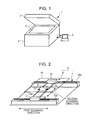
- Fig. 1 is an outside view of a fluorescence information reading device according to an embodiment.
- a fluorescence information reading device 1 is roughly composed of a body 2 that forms a housing, and a cover 3 that covers an upper surface of the body 2.
- a sample table 4 made of glass is provided on the upper surface of the body 2.
- a gel support or a transfer support, such as a membrane, in which biogenic substances labeled by a fluorescent substance (both of the supports are not illustrated) is set as a sample on the sample table 4.
- Optical systems are disposed on a lower side of the sample table 4. Excitation light is applied to the sample set on the sample table 4 from below through the sample table 4 by an irradiation optical system, and fluorescence from the sample, which passes through the sample table 4, is detected by a detection optical system.
- the detection optical system is connected to an external terminal such as a PC (Personal computer) 5, and for example, a measuring condition is controlled from the PC 5. Further, the PC 5 creates a fluorescence image of the sample on the basis of detected data, and displays the created fluorescence image or the like on an incorporated display screen.
- PC Personal computer
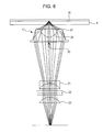
- Fig. 2 is an outside view of a scanning stage 6 installed below the sample table 4.
- This scanning stage 6 includes a first stage 7 serving as a base, and a second stage 8 disposed on the first stage 7.
- a scanning module 9 is disposed on the second stage 8.
- the detection optical system for detecting the fluorescence is stored in the scanning module 9.
- the second stage 8 includes a first guide member 11 that is guided by the guide rail 10a of the first stage 7 to reciprocate in the first scanning direction, and a second guide member 12 that is guided by the guide rail 10b to reciprocate in the first scanning direction.
- the scanning module 9 is provided with a first guide member 14 that is guided by the guide rail 13a to reciprocate in the second scanning direction, and a second guide member 15 that is guided by the guide rail 13b to reciprocate in the second scanning direction.
- the first guide member 11 and the second guide member 12 of the second stage 8 are moved in the first scanning direction while being guided by the guide rails 10a and 10b, respectively, so as to position the second stage 8 relative to the first stage 7.
- the first guide member 14 and the second guide member 15 of the scanning module 9 are moved in the second scanning direction while being guided by the guide rails 13a and 13b, respectively, so as to position the scanning module 9 relative to the second stage 8.
- a sample 16 is two-dimensionally scanned by repeating the above operations.
- a moving unit in the first scanning direction is constituted by the guide rails 10a and 10b and the first and second guide members 11 and 12, and a moving unit in the second scanning direction is constituted by the guide rails 13a and 13b and the first and second guide members 14 and 15.
- driving units such as a motor, a driving belt, ball screws, gears, a control board, a power supply, and wires, are disposed to move the first and second guide members 11 and 12 of the second stage 8 in the first scanning direction and to move the first and second guide members 14 and 15 of the scanning module 9 in the second scanning direction.
- the scanning stage 6 and the driving units constitute the scanning mechanism in the claims.
- Fig. 3 is a longitudinal sectional view illustrating a schematic structure of the scanning module 9 disposed on the second stage 8.
- an objective lens 17 is disposed in an upper part of the scanning module 9 and near the sample table (glass) 4 to collect fluorescence from a sample 16 set on the sample table 4.
- a prism 20 is disposed at a position, where the optical axis of the objective lens 17 and the optical axis of a light source 18 of excitation light intersect at right angles, to reflect excitation light, such as laser light, emitted from the light source 18 and collected by a first lens 19 so that the excitation light enters the objective lens 17.
- a second lens 21 for converting fluorescence from the sample 16 collected by the objective lens 17 into parallel light, a cutting wavelength filter 22 for cutting excitation light, a third lens 23 for collecting fluorescence passing through the wavelength filter 22, and a pinhole 24 for cutting stray light of fluorescence passing through the third lens 23 are disposed in order from a side of the prism 20. Further, below the pinhole 24 on the optical axis of the objective lens 17, a detector 25 is disposed to detect fluorescence passing through the pinhole 24.
- excitation light emitted from the light source 18 is converged by the first lens 19, is next reflected by the prism 20, passes through the objective lens 17 and the sample table 4, and is collected at one point on a lower surface of the sample 16.
- the length of the prism 20 in a longitudinal direction (a direction orthogonal to the optical axis of the first lens 19) is short, and the width thereof in a direction orthogonal to the longitudinal direction is narrow.
- the excitation light from the light source 18 passes only near the optical axis of the objective lens 17 (an excitation-light transmitting portion).
- the light source 18, the first lens 19, and the prism 20 constitute the light source unit in the claims.
- the fluorescence is isotropically emitted around from a portion of the sample 16 irradiated with the excitation light.
- a component of the emitted fluorescence which has passed through the sample table 4 made of glass and entered the objective lens 17, passes through the objective lens 17, the second lens 21, the wavelength filter 22, the third lens 23, and the pinhole 24, and is detected by the detector 25.
- Signals detected by the detector 25 are subjected to processing, for example, AD conversion by an AD converter incorporated therein, and are then transmitted to the PC 5.
- processing for example, AD conversion by an AD converter incorporated therein
- the fluorescence that has passed through the objective lens 17 is guided as convergent light toward the second lens 21. Then, the fluorescence is refracted by the second lens 21 so as to become substantially parallel light. Further, the third lens 23 collects the fluorescence.
- the pinhole 24 is disposed to spatially cut stray light.
- the wavelength filter 22 for cutting excitation light is disposed in, for example, a rotary folder (not illustrated), and can be replaced with other wavelength filters in accordance with the wavelength of the excitation light.
- Fig. 4 includes perspective views of the objective lens 17.
- Fig. 4(a) is a perspective view from the prism 20.
- Fig. 4(b) is a perspective view from the sample table 4.
- Fig. 5 is a longitudinal sectional view of the objective lens 17.
- the objective lens 17 is shaped like an inverted ashtray.
- a center portion including the optical axis includes an upper convex surface 26a and a lower convex surface 26b that spherically project along the optical axis, and serves as a convex lens part 26 having a function of a normal convex lens (function of deflecting light only by refraction).
- a fluorescence component a with a small emission angle, of fluorescence emitted from the sample 16 passes through the convex lens part 26, and is collected toward the detector 25.
- a portion of the objective lens 17 around the lower convex surface 26b (convex lens part 26) serves as a truncated conical cylindrical body 27 opening downward.
- a fluorescence component b having too wide an emission angle to fit in the convex lens part 26, of the fluorescence emitted from the sample 16 enters the cylindrical body 27 from an upper end surface 27a of the cylindrical body 27, is deflected toward the optical axis by total reflection on an outer peripheral surface 27b of the cylindrical body 27, and is emitted from a lower end surface 27c of the cylindrical body 27 toward the detector 25.
- the convex lens part 26 forms the center portion in the claims, and the cylindrical body 27 forms the peripheral portion.
- the lens element itself can be made more compact than when the objective lens of this fluorescence information reading device 1 is realized by a normal convex lens having an NA equal to that of the objective lens 17.
- Fig. 6 is a ray diagram of fluorescence that is emitted from the sample 16 and passes from the objective lens 17 to the third lens 23.
- an interference filter having a sharp cutoff property is used as the wavelength filter 22, it is necessary to convert incident light on the wavelength filter 22 into parallel light. Accordingly, fluorescence collected through the objective lens 17 is caused to be incident on the wavelength filter 22 after being converted into substantially parallel light by the second lens 21.
- the fluorescence can be converted into parallel light by the objective lens 17. In this case, however, the beam diameter of fluorescence increases, and this increases the sizes of the second lens 21 and the subsequent optical elements.
- the sizes of the optical elements that is, the second lens 21, the wavelength filter 22, and the third lens 23 can be reduced, and the size and weight of the scanning module 9 can be reduced.
- the number of wavelength filters 22 to be mounted can be increased by reducing the size of the wavelength filter 22. This can increase the number of kinds of measurable fluorescence reagents.
- a lens having a convex lens part in a center portion and a truncated conical cylindrical body around the convex lens part is disclosed in Japanese Unexamined Patent Application Publication No. 2007-266180 and International Publication No. WO 2008/069143 .
- both of these patent literatures relate to a light emitting lens that allows light from a light emitting element, such as an LED, to be emitted forward with high directivity, but do not disclose and suggest the point in that a lens similar to the light emitting lens is used as an objective lens in a fluorescence information reading device and the point in that optical elements of the fluorescence information reading device are reduced in size by using the lens as the objective lens.
- the sample table 4 made of glass is provided on the upper surface of the body 2 that forms the housing, and for example, a gel support or a transfer support, in which biogenic substances labeled by a fluorescent material are distributed, is set as a sample 16 on the sample table 4.
- the scanning module 9 that performs two-dimensional scanning by being moved in the first scanning direction and the second scanning direction by the scanning stage 6 disposed below the sample table 4, the irradiation optical system constituted by the light source 18, the first lens 19, the prism 20, and the objective lens 17 is disposed.
- the objective lens 17 transmits excitation light emitted from the light source 18, collected by the first lens 19, and reflected by the prism 20 so as to irradiate the sample 16. Then, the objective lens 17 collects fluorescence from the sample 16.
- the detection optical system is contained integrally, which is constituted by the second lens 21 for converting fluorescence collected by the objective lens 17 into substantially parallel light, the cutting wavelength filter 22 for cutting excitation light, the third lens 23 for collecting the fluorescence, the pinhole 24 for cutting stray light, and the detector 25 for detecting the fluorescence.
- the objective lens 17 is structured to have the convex lens part 26 in the center portion and the truncated conical cylindrical body 27 around the convex lens part 26. Therefore, the fluorescence component b having too wide an emission angle to fit in the convex lens part 26, of the fluorescence emitted from the sample 16, can be totally reflected and collected by the outer peripheral surface 27b of the cylindrical body 27, and even light having too wide an emission angle to be collected by the normal convex lens can be collected. As a result, the light collection efficiency of the fluorescence can be enhanced, and the S/N ratio can be prevented from being decreased by the existence of fluorescence that is blocked by the prism 20 disposed on the optical axis of the objective lens 17 and is not detected by the detector 25. Thus, a fluorescence information reading device having high sensitivity can be realized.
- the scanning mechanism for two-dimensional scanning is not complicated.
- the size of the objective lens 17 can be made smaller than when the fluorescence component b having a wide emission angle is collected by the normal convex lens having high NA. Further, since the objective lens 17 collects fluorescence from the sample 16 and causes the fluorescence to enter the second lens 21, the sizes of the optical elements disposed on the optical path along which the fluorescence is guided to the detector 25, such as the second lens 21, the wavelength filter 22, and the third lens 23, can also be reduced.
- the weight of the scanning module 9 that incorporates the irradiation optical system and the detection optical system can be reduced. Therefore, it is possible to simplify the structure of the scanning mechanism and to reduce the weight of the scanning mechanism so that the scanning module 9 can perform high-speed scanning. Therefore, it is possible to detect a two-dimensional distribution of fluorescence at a plurality of different positions on the sample 16 at high speed.
- the objective lens 17 has a concentric planar shape that is symmetrical with respect to the center axis serving as the optical axis. This center axis overlaps with at least a part of an optical path along which the excitation light reflected by the prism 20 passes. For this reason, compared to the method in which excitation light is applied through the dichroic mirror, greater excitation energy can be applied to the sample 16. This can increase the S/N ratio of signals (information signals) photoelectrically detected by the detector 25.
- the sample 16 is set on the light-transmissive sample table 4, and the scanning module 9 including the detector 25 for detecting fluorescence is disposed opposed to a surface of the sample table 4 opposite from a setting surface for the sample 16.
- the detector 25 detects fluorescence from the sample 16 via the sample table 4. Therefore, it is only necessary to lay the two-dimensional sample 16 flat on the sample table 4, and this allows easy setup of the sample 16. Further, the detector 25 for fluorescence can be disposed on the same side of the sample table 4 as the light source 18 for excitation light, and the light source 18 can be disposed in the scanning module 9. Thus, the total size of the optical system can be reduced.
- excitation light is applied from the single light source 18 to the sample 16 in the above embodiment, a plurality of light sources may be provided to selectively apply excitation lights having different wavelengths in accordance with the wavelength of the fluorescent substance that labels biogenic substances on the sample 16.
- the wavelength filter 22 for cutting excitation light is disposed in the rotary holder or the like, and can be replaced with other wavelength filters in accordance with the wavelength of the excitation light.
- the present invention is not limited thereto, and a plurality of wavelength filters can be stacked movably forward and backward, and a filter for a target wavelength can be moved forward in accordance with the wavelength of the excitation light.
Landscapes
- Physics & Mathematics (AREA)
- Health & Medical Sciences (AREA)
- General Physics & Mathematics (AREA)
- Life Sciences & Earth Sciences (AREA)
- Chemical & Material Sciences (AREA)
- Analytical Chemistry (AREA)
- Biochemistry (AREA)
- General Health & Medical Sciences (AREA)
- Nuclear Medicine, Radiotherapy & Molecular Imaging (AREA)
- Immunology (AREA)
- Pathology (AREA)
- Optics & Photonics (AREA)
- Engineering & Computer Science (AREA)
- Biomedical Technology (AREA)
- Molecular Biology (AREA)
- Investigating, Analyzing Materials By Fluorescence Or Luminescence (AREA)
Applications Claiming Priority (2)
| Application Number | Priority Date | Filing Date | Title |
|---|---|---|---|
| JP2012014183A JP5575159B2 (ja) | 2012-01-26 | 2012-01-26 | 蛍光情報読み取り装置および蛍光情報読み取り方法 |
| PCT/JP2012/080853 WO2013111446A1 (ja) | 2012-01-26 | 2012-11-29 | 蛍光情報読み取り装置および蛍光情報読み取り方法 |
Publications (2)
| Publication Number | Publication Date |
|---|---|
| EP2808671A1 true EP2808671A1 (de) | 2014-12-03 |
| EP2808671A4 EP2808671A4 (de) | 2015-08-26 |
Family
ID=48873187
Family Applications (1)
| Application Number | Title | Priority Date | Filing Date |
|---|---|---|---|
| EP12866837.3A Withdrawn EP2808671A4 (de) | 2012-01-26 | 2012-11-29 | Fluoreszenzinformationslesevorrichtung und fluoreszenzinformationsleseverfahren |
Country Status (4)
| Country | Link |
|---|---|
| US (1) | US9562992B2 (de) |
| EP (1) | EP2808671A4 (de) |
| JP (1) | JP5575159B2 (de) |
| WO (1) | WO2013111446A1 (de) |
Cited By (4)
| Publication number | Priority date | Publication date | Assignee | Title |
|---|---|---|---|---|
| WO2020157077A3 (en) * | 2019-01-28 | 2020-09-17 | Cellink Ab | A compact fluorescence microscope and a cell monitoring system |
| US11186736B2 (en) | 2018-10-10 | 2021-11-30 | Cellink Ab | Double network bioinks |
| US11826951B2 (en) | 2019-09-06 | 2023-11-28 | Cellink Ab | Temperature-controlled multi-material overprinting |
| US11931966B2 (en) | 2018-01-26 | 2024-03-19 | Cellink Bioprinting Ab | Systems and methods for optical assessments of bioink printability |
Families Citing this family (4)
| Publication number | Priority date | Publication date | Assignee | Title |
|---|---|---|---|---|
| JP2014006196A (ja) * | 2012-06-26 | 2014-01-16 | Sharp Corp | 蛍光検出装置 |
| JP5745492B2 (ja) * | 2012-11-08 | 2015-07-08 | シャープ株式会社 | 光検出装置 |
| KR101761128B1 (ko) * | 2016-04-18 | 2017-07-25 | 전자부품연구원 | 바이오센서용 형광광학계 |
| KR101891232B1 (ko) * | 2016-12-20 | 2018-10-02 | 미라클스코프(주) | 형광 검출을 위한 광학헤드 |
Family Cites Families (20)
| Publication number | Priority date | Publication date | Assignee | Title |
|---|---|---|---|---|
| US2224178A (en) * | 1940-05-08 | 1940-12-10 | Ralph E Bitner | Catadioptrical lens system |
| US5528050A (en) * | 1995-07-24 | 1996-06-18 | Molecular Dynamics, Inc. | Compact scan head with multiple scanning modalities |
| KR100230253B1 (ko) * | 1996-02-14 | 1999-11-15 | 윤종용 | 대물렌즈 장치 및 이의 제작방법 및 이를 적용한 광픽업장치 |
| JPH103134A (ja) | 1996-06-18 | 1998-01-06 | Fuji Photo Film Co Ltd | 画像読み取り装置 |
| CN1133996C (zh) * | 1997-11-22 | 2004-01-07 | 三星电子株式会社 | 反射折射光学系统、采用该系统的光拾取器、光盘驱动器 |
| KR100294237B1 (ko) * | 1998-04-14 | 2001-09-17 | 윤종용 | 카타디옵트릭 대물렌즈를 구비한 광픽업 |
| JP2000162126A (ja) * | 1998-11-25 | 2000-06-16 | Fuji Photo Film Co Ltd | 画像情報読取装置 |
| KR100483706B1 (ko) | 2002-04-04 | 2005-04-18 | 바디텍메드 주식회사 | 레이저 유발 표면형광 검출 장치 |
| EP1617204A4 (de) * | 2003-04-23 | 2008-07-30 | Olympus Corp | Verfahren zur analyse molekularer fluoreszenz mittels evaneszenz-beleuchtung |
| JP2005174693A (ja) * | 2003-12-10 | 2005-06-30 | Okaya Electric Ind Co Ltd | 発光素子用レンズ |
| US7262859B2 (en) * | 2004-10-13 | 2007-08-28 | U.S. Genomics, Inc. | Systems and methods for measurement optimization |
| US7643226B2 (en) * | 2005-10-03 | 2010-01-05 | Salk Institute For Biological Studies | Maximal-aperture reflecting objective |
| JP2007266180A (ja) | 2006-03-28 | 2007-10-11 | Okaya Electric Ind Co Ltd | 発光素子用レンズ |
| JPWO2008069143A1 (ja) | 2006-12-05 | 2010-03-18 | 株式会社ニコン | 照明光源及び画像投影装置 |
| JP5254744B2 (ja) * | 2008-10-31 | 2013-08-07 | 株式会社エンプラス | 照明用レンズおよびこれを備えた照明装置 |
| CN102472471A (zh) * | 2009-08-24 | 2012-05-23 | 松下电器产业株式会社 | 透镜和使用其的半导体发光元件模块 |
| TWI432790B (zh) * | 2010-04-29 | 2014-04-01 | Univ Nat Changhua Education | The collimating lens structure with free - form surface and its design method |
| GB2480293A (en) * | 2010-05-12 | 2011-11-16 | Univ Dublin City | A luminescence based sensor |
| JP2011257216A (ja) * | 2010-06-08 | 2011-12-22 | Konica Minolta Holdings Inc | 表面プラズモン増強蛍光センサおよび表面プラズモン増強蛍光センサに用いられるチップ構造体ユニット |
| JP5497088B2 (ja) * | 2012-03-21 | 2014-05-21 | シャープ株式会社 | 光学ユニット、蛍光検出装置、および、蛍光検出方法 |
-
2012
- 2012-01-26 JP JP2012014183A patent/JP5575159B2/ja not_active Expired - Fee Related
- 2012-11-29 EP EP12866837.3A patent/EP2808671A4/de not_active Withdrawn
- 2012-11-29 WO PCT/JP2012/080853 patent/WO2013111446A1/ja not_active Ceased
- 2012-11-29 US US14/373,646 patent/US9562992B2/en not_active Expired - Fee Related
Cited By (4)
| Publication number | Priority date | Publication date | Assignee | Title |
|---|---|---|---|---|
| US11931966B2 (en) | 2018-01-26 | 2024-03-19 | Cellink Bioprinting Ab | Systems and methods for optical assessments of bioink printability |
| US11186736B2 (en) | 2018-10-10 | 2021-11-30 | Cellink Ab | Double network bioinks |
| WO2020157077A3 (en) * | 2019-01-28 | 2020-09-17 | Cellink Ab | A compact fluorescence microscope and a cell monitoring system |
| US11826951B2 (en) | 2019-09-06 | 2023-11-28 | Cellink Ab | Temperature-controlled multi-material overprinting |
Also Published As
| Publication number | Publication date |
|---|---|
| WO2013111446A1 (ja) | 2013-08-01 |
| EP2808671A4 (de) | 2015-08-26 |
| US9562992B2 (en) | 2017-02-07 |
| US20150008338A1 (en) | 2015-01-08 |
| JP2013152202A (ja) | 2013-08-08 |
| JP5575159B2 (ja) | 2014-08-20 |
Similar Documents
| Publication | Publication Date | Title |
|---|---|---|
| US9562992B2 (en) | Fluorescence information reading device and fluorescence information reading method | |
| EP2829901B1 (de) | Optische einheit, fluoreszenzdetektor und fluoreszenzdetektionsverfahren | |
| US9285321B2 (en) | Fluorescence detection device | |
| JPH10504916A (ja) | Led点走査システム | |
| US7016087B2 (en) | Photon efficient scanner | |
| CN107576639A (zh) | 便携式全集成dna现场检验微型全分析系统检测光路 | |
| US20070131870A1 (en) | Multiplexed CE fluorescence system | |
| JP2022528323A (ja) | 周波数符号化画像に基づく細胞選別のシステムとその使用方法 | |
| EP1438615A4 (de) | Abbilden von mikroarrays mit einem faseroptischen erreger | |
| US12184037B2 (en) | Multi-modal imaging systems and methods | |
| US6762840B1 (en) | Image information reading apparatus designed to maintain light amount to be detected at uniform level | |
| CN105973860A (zh) | 一种毛细管电泳检测系统及检测方法 | |
| US20150292940A1 (en) | Photodetection apparatus | |
| WO2014064993A1 (ja) | レンズ素子 | |
| JP4887475B2 (ja) | 自己蛍光を除去するために複数の検出チャネルを使用するシステム及び方法 | |
| JP2000162126A (ja) | 画像情報読取装置 | |
| CN201014990Y (zh) | 激光诱导荧光共聚焦扫描装置 | |
| JP5899038B2 (ja) | 蛍光検出装置および蛍光検出方法 | |
| JP2014071059A (ja) | 光検出装置 | |
| JP2014052252A (ja) | 蛍光検出装置 | |
| US11543639B2 (en) | Macro-micro telecentric scanning systems and methods | |
| WO2013191040A1 (ja) | 蛍光検出装置 |
Legal Events
| Date | Code | Title | Description |
|---|---|---|---|
| PUAI | Public reference made under article 153(3) epc to a published international application that has entered the european phase |
Free format text: ORIGINAL CODE: 0009012 |
|
| 17P | Request for examination filed |
Effective date: 20140724 |
|
| AK | Designated contracting states |
Kind code of ref document: A1 Designated state(s): AL AT BE BG CH CY CZ DE DK EE ES FI FR GB GR HR HU IE IS IT LI LT LU LV MC MK MT NL NO PL PT RO RS SE SI SK SM TR |
|
| DAX | Request for extension of the european patent (deleted) | ||
| RIN1 | Information on inventor provided before grant (corrected) |
Inventor name: WATANABE, YUKIO |
|
| RA4 | Supplementary search report drawn up and despatched (corrected) |
Effective date: 20150723 |
|
| RIC1 | Information provided on ipc code assigned before grant |
Ipc: G01N 21/64 20060101AFI20150717BHEP |
|
| RAP1 | Party data changed (applicant data changed or rights of an application transferred) |
Owner name: SHARP LIFE SCIENCE CORPORATION |
|
| STAA | Information on the status of an ep patent application or granted ep patent |
Free format text: STATUS: THE APPLICATION HAS BEEN WITHDRAWN |
|
| 18W | Application withdrawn |
Effective date: 20170905 |