EP2808190B1 - Système et procédé de commande de véhicule - Google Patents
Système et procédé de commande de véhicule Download PDFInfo
- Publication number
- EP2808190B1 EP2808190B1 EP13740909.0A EP13740909A EP2808190B1 EP 2808190 B1 EP2808190 B1 EP 2808190B1 EP 13740909 A EP13740909 A EP 13740909A EP 2808190 B1 EP2808190 B1 EP 2808190B1
- Authority
- EP
- European Patent Office
- Prior art keywords
- damping
- control amount
- control
- damping force
- vehicle
- Prior art date
- Legal status (The legal status is an assumption and is not a legal conclusion. Google has not performed a legal analysis and makes no representation as to the accuracy of the status listed.)
- Active
Links
- 238000000034 method Methods 0.000 title claims description 54
- 238000013016 damping Methods 0.000 claims description 363
- 238000009826 distribution Methods 0.000 claims description 41
- 239000006096 absorbing agent Substances 0.000 claims description 15
- 230000035939 shock Effects 0.000 claims description 15
- 230000008569 process Effects 0.000 description 50
- 230000001133 acceleration Effects 0.000 description 33
- 230000033001 locomotion Effects 0.000 description 28
- 238000010586 diagram Methods 0.000 description 26
- 230000005484 gravity Effects 0.000 description 11
- 230000035807 sensation Effects 0.000 description 11
- 239000000725 suspension Substances 0.000 description 8
- 230000002441 reversible effect Effects 0.000 description 7
- 230000036461 convulsion Effects 0.000 description 6
- 230000000694 effects Effects 0.000 description 6
- 238000005096 rolling process Methods 0.000 description 6
- 230000005540 biological transmission Effects 0.000 description 4
- 230000015556 catabolic process Effects 0.000 description 4
- 238000006731 degradation reaction Methods 0.000 description 4
- 239000012530 fluid Substances 0.000 description 4
- 230000004044 response Effects 0.000 description 4
- 238000004364 calculation method Methods 0.000 description 3
- 238000011109 contamination Methods 0.000 description 3
- 230000000644 propagated effect Effects 0.000 description 3
- 239000013598 vector Substances 0.000 description 3
- 230000008901 benefit Effects 0.000 description 2
- 230000015572 biosynthetic process Effects 0.000 description 2
- 230000008859 change Effects 0.000 description 2
- 239000013256 coordination polymer Substances 0.000 description 2
- 230000003247 decreasing effect Effects 0.000 description 2
- 230000003111 delayed effect Effects 0.000 description 2
- 230000001687 destabilization Effects 0.000 description 2
- 230000008030 elimination Effects 0.000 description 2
- 238000003379 elimination reaction Methods 0.000 description 2
- 238000005516 engineering process Methods 0.000 description 2
- 230000005713 exacerbation Effects 0.000 description 2
- 238000011946 reduction process Methods 0.000 description 2
- 230000000630 rising effect Effects 0.000 description 2
- 230000035945 sensitivity Effects 0.000 description 2
- 230000009471 action Effects 0.000 description 1
- 239000012190 activator Substances 0.000 description 1
- 230000003190 augmentative effect Effects 0.000 description 1
- 238000006243 chemical reaction Methods 0.000 description 1
- 230000000295 complement effect Effects 0.000 description 1
- 238000010276 construction Methods 0.000 description 1
- 230000007423 decrease Effects 0.000 description 1
- 230000000593 degrading effect Effects 0.000 description 1
- 230000003090 exacerbative effect Effects 0.000 description 1
- 230000001747 exhibiting effect Effects 0.000 description 1
- 239000000284 extract Substances 0.000 description 1
- 238000007667 floating Methods 0.000 description 1
- 239000000446 fuel Substances 0.000 description 1
- 230000006870 function Effects 0.000 description 1
- 238000002347 injection Methods 0.000 description 1
- 239000007924 injection Substances 0.000 description 1
- 238000009434 installation Methods 0.000 description 1
- 238000004519 manufacturing process Methods 0.000 description 1
- 230000004048 modification Effects 0.000 description 1
- 238000012986 modification Methods 0.000 description 1
- 230000010363 phase shift Effects 0.000 description 1
- 230000009467 reduction Effects 0.000 description 1
- 239000000243 solution Substances 0.000 description 1
- 230000006641 stabilisation Effects 0.000 description 1
- 238000011105 stabilization Methods 0.000 description 1
- 210000000689 upper leg Anatomy 0.000 description 1
- 238000004804 winding Methods 0.000 description 1
Images


Classifications
-
- B—PERFORMING OPERATIONS; TRANSPORTING
- B60—VEHICLES IN GENERAL
- B60G—VEHICLE SUSPENSION ARRANGEMENTS
- B60G17/00—Resilient suspensions having means for adjusting the spring or vibration-damper characteristics, for regulating the distance between a supporting surface and a sprung part of vehicle or for locking suspension during use to meet varying vehicular or surface conditions, e.g. due to speed or load
- B60G17/015—Resilient suspensions having means for adjusting the spring or vibration-damper characteristics, for regulating the distance between a supporting surface and a sprung part of vehicle or for locking suspension during use to meet varying vehicular or surface conditions, e.g. due to speed or load the regulating means comprising electric or electronic elements
- B60G17/016—Resilient suspensions having means for adjusting the spring or vibration-damper characteristics, for regulating the distance between a supporting surface and a sprung part of vehicle or for locking suspension during use to meet varying vehicular or surface conditions, e.g. due to speed or load the regulating means comprising electric or electronic elements characterised by their responsiveness, when the vehicle is travelling, to specific motion, a specific condition, or driver input
- B60G17/0165—Resilient suspensions having means for adjusting the spring or vibration-damper characteristics, for regulating the distance between a supporting surface and a sprung part of vehicle or for locking suspension during use to meet varying vehicular or surface conditions, e.g. due to speed or load the regulating means comprising electric or electronic elements characterised by their responsiveness, when the vehicle is travelling, to specific motion, a specific condition, or driver input to an external condition, e.g. rough road surface, side wind
-
- B—PERFORMING OPERATIONS; TRANSPORTING
- B60—VEHICLES IN GENERAL
- B60G—VEHICLE SUSPENSION ARRANGEMENTS
- B60G17/00—Resilient suspensions having means for adjusting the spring or vibration-damper characteristics, for regulating the distance between a supporting surface and a sprung part of vehicle or for locking suspension during use to meet varying vehicular or surface conditions, e.g. due to speed or load
- B60G17/015—Resilient suspensions having means for adjusting the spring or vibration-damper characteristics, for regulating the distance between a supporting surface and a sprung part of vehicle or for locking suspension during use to meet varying vehicular or surface conditions, e.g. due to speed or load the regulating means comprising electric or electronic elements
- B60G17/016—Resilient suspensions having means for adjusting the spring or vibration-damper characteristics, for regulating the distance between a supporting surface and a sprung part of vehicle or for locking suspension during use to meet varying vehicular or surface conditions, e.g. due to speed or load the regulating means comprising electric or electronic elements characterised by their responsiveness, when the vehicle is travelling, to specific motion, a specific condition, or driver input
- B60G17/0162—Resilient suspensions having means for adjusting the spring or vibration-damper characteristics, for regulating the distance between a supporting surface and a sprung part of vehicle or for locking suspension during use to meet varying vehicular or surface conditions, e.g. due to speed or load the regulating means comprising electric or electronic elements characterised by their responsiveness, when the vehicle is travelling, to specific motion, a specific condition, or driver input mainly during a motion involving steering operation, e.g. cornering, overtaking
-
- B—PERFORMING OPERATIONS; TRANSPORTING
- B60—VEHICLES IN GENERAL
- B60G—VEHICLE SUSPENSION ARRANGEMENTS
- B60G17/00—Resilient suspensions having means for adjusting the spring or vibration-damper characteristics, for regulating the distance between a supporting surface and a sprung part of vehicle or for locking suspension during use to meet varying vehicular or surface conditions, e.g. due to speed or load
- B60G17/015—Resilient suspensions having means for adjusting the spring or vibration-damper characteristics, for regulating the distance between a supporting surface and a sprung part of vehicle or for locking suspension during use to meet varying vehicular or surface conditions, e.g. due to speed or load the regulating means comprising electric or electronic elements
- B60G17/016—Resilient suspensions having means for adjusting the spring or vibration-damper characteristics, for regulating the distance between a supporting surface and a sprung part of vehicle or for locking suspension during use to meet varying vehicular or surface conditions, e.g. due to speed or load the regulating means comprising electric or electronic elements characterised by their responsiveness, when the vehicle is travelling, to specific motion, a specific condition, or driver input
- B60G17/0164—Resilient suspensions having means for adjusting the spring or vibration-damper characteristics, for regulating the distance between a supporting surface and a sprung part of vehicle or for locking suspension during use to meet varying vehicular or surface conditions, e.g. due to speed or load the regulating means comprising electric or electronic elements characterised by their responsiveness, when the vehicle is travelling, to specific motion, a specific condition, or driver input mainly during accelerating or braking
-
- B—PERFORMING OPERATIONS; TRANSPORTING
- B60—VEHICLES IN GENERAL
- B60G—VEHICLE SUSPENSION ARRANGEMENTS
- B60G17/00—Resilient suspensions having means for adjusting the spring or vibration-damper characteristics, for regulating the distance between a supporting surface and a sprung part of vehicle or for locking suspension during use to meet varying vehicular or surface conditions, e.g. due to speed or load
- B60G17/015—Resilient suspensions having means for adjusting the spring or vibration-damper characteristics, for regulating the distance between a supporting surface and a sprung part of vehicle or for locking suspension during use to meet varying vehicular or surface conditions, e.g. due to speed or load the regulating means comprising electric or electronic elements
- B60G17/018—Resilient suspensions having means for adjusting the spring or vibration-damper characteristics, for regulating the distance between a supporting surface and a sprung part of vehicle or for locking suspension during use to meet varying vehicular or surface conditions, e.g. due to speed or load the regulating means comprising electric or electronic elements characterised by the use of a specific signal treatment or control method
- B60G17/0182—Resilient suspensions having means for adjusting the spring or vibration-damper characteristics, for regulating the distance between a supporting surface and a sprung part of vehicle or for locking suspension during use to meet varying vehicular or surface conditions, e.g. due to speed or load the regulating means comprising electric or electronic elements characterised by the use of a specific signal treatment or control method involving parameter estimation, e.g. observer, Kalman filter
-
- B—PERFORMING OPERATIONS; TRANSPORTING
- B60—VEHICLES IN GENERAL
- B60G—VEHICLE SUSPENSION ARRANGEMENTS
- B60G17/00—Resilient suspensions having means for adjusting the spring or vibration-damper characteristics, for regulating the distance between a supporting surface and a sprung part of vehicle or for locking suspension during use to meet varying vehicular or surface conditions, e.g. due to speed or load
- B60G17/015—Resilient suspensions having means for adjusting the spring or vibration-damper characteristics, for regulating the distance between a supporting surface and a sprung part of vehicle or for locking suspension during use to meet varying vehicular or surface conditions, e.g. due to speed or load the regulating means comprising electric or electronic elements
- B60G17/0195—Resilient suspensions having means for adjusting the spring or vibration-damper characteristics, for regulating the distance between a supporting surface and a sprung part of vehicle or for locking suspension during use to meet varying vehicular or surface conditions, e.g. due to speed or load the regulating means comprising electric or electronic elements characterised by the regulation being combined with other vehicle control systems
-
- B—PERFORMING OPERATIONS; TRANSPORTING
- B60—VEHICLES IN GENERAL
- B60G—VEHICLE SUSPENSION ARRANGEMENTS
- B60G17/00—Resilient suspensions having means for adjusting the spring or vibration-damper characteristics, for regulating the distance between a supporting surface and a sprung part of vehicle or for locking suspension during use to meet varying vehicular or surface conditions, e.g. due to speed or load
- B60G17/06—Characteristics of dampers, e.g. mechanical dampers
- B60G17/08—Characteristics of fluid dampers
-
- B—PERFORMING OPERATIONS; TRANSPORTING
- B60—VEHICLES IN GENERAL
- B60G—VEHICLE SUSPENSION ARRANGEMENTS
- B60G2400/00—Indexing codes relating to detected, measured or calculated conditions or factors
- B60G2400/05—Attitude
- B60G2400/052—Angular rate
- B60G2400/0521—Roll rate
-
- B—PERFORMING OPERATIONS; TRANSPORTING
- B60—VEHICLES IN GENERAL
- B60G—VEHICLE SUSPENSION ARRANGEMENTS
- B60G2400/00—Indexing codes relating to detected, measured or calculated conditions or factors
- B60G2400/05—Attitude
- B60G2400/052—Angular rate
- B60G2400/0522—Pitch rate
-
- B—PERFORMING OPERATIONS; TRANSPORTING
- B60—VEHICLES IN GENERAL
- B60G—VEHICLE SUSPENSION ARRANGEMENTS
- B60G2400/00—Indexing codes relating to detected, measured or calculated conditions or factors
- B60G2400/05—Attitude
- B60G2400/052—Angular rate
- B60G2400/0523—Yaw rate
-
- B—PERFORMING OPERATIONS; TRANSPORTING
- B60—VEHICLES IN GENERAL
- B60G—VEHICLE SUSPENSION ARRANGEMENTS
- B60G2400/00—Indexing codes relating to detected, measured or calculated conditions or factors
- B60G2400/20—Speed
- B60G2400/204—Vehicle speed
-
- B—PERFORMING OPERATIONS; TRANSPORTING
- B60—VEHICLES IN GENERAL
- B60G—VEHICLE SUSPENSION ARRANGEMENTS
- B60G2400/00—Indexing codes relating to detected, measured or calculated conditions or factors
- B60G2400/20—Speed
- B60G2400/206—Body oscillation speed; Body vibration frequency
-
- B—PERFORMING OPERATIONS; TRANSPORTING
- B60—VEHICLES IN GENERAL
- B60G—VEHICLE SUSPENSION ARRANGEMENTS
- B60G2400/00—Indexing codes relating to detected, measured or calculated conditions or factors
- B60G2400/20—Speed
- B60G2400/208—Speed of wheel rotation
-
- B—PERFORMING OPERATIONS; TRANSPORTING
- B60—VEHICLES IN GENERAL
- B60G—VEHICLE SUSPENSION ARRANGEMENTS
- B60G2400/00—Indexing codes relating to detected, measured or calculated conditions or factors
- B60G2400/30—Propulsion unit conditions
-
- B—PERFORMING OPERATIONS; TRANSPORTING
- B60—VEHICLES IN GENERAL
- B60G—VEHICLE SUSPENSION ARRANGEMENTS
- B60G2400/00—Indexing codes relating to detected, measured or calculated conditions or factors
- B60G2400/40—Steering conditions
-
- B—PERFORMING OPERATIONS; TRANSPORTING
- B60—VEHICLES IN GENERAL
- B60G—VEHICLE SUSPENSION ARRANGEMENTS
- B60G2400/00—Indexing codes relating to detected, measured or calculated conditions or factors
- B60G2400/60—Load
- B60G2400/64—Wheel forces, e.g. on hub, spindle or bearing
-
- B—PERFORMING OPERATIONS; TRANSPORTING
- B60—VEHICLES IN GENERAL
- B60G—VEHICLE SUSPENSION ARRANGEMENTS
- B60G2400/00—Indexing codes relating to detected, measured or calculated conditions or factors
- B60G2400/80—Exterior conditions
- B60G2400/82—Ground surface
- B60G2400/821—Uneven, rough road sensing affecting vehicle body vibration
-
- B—PERFORMING OPERATIONS; TRANSPORTING
- B60—VEHICLES IN GENERAL
- B60G—VEHICLE SUSPENSION ARRANGEMENTS
- B60G2400/00—Indexing codes relating to detected, measured or calculated conditions or factors
- B60G2400/90—Other conditions or factors
- B60G2400/91—Frequency
-
- B—PERFORMING OPERATIONS; TRANSPORTING
- B60—VEHICLES IN GENERAL
- B60G—VEHICLE SUSPENSION ARRANGEMENTS
- B60G2500/00—Indexing codes relating to the regulated action or device
- B60G2500/10—Damping action or damper
- B60G2500/106—Damping action or damper duty rate
-
- B—PERFORMING OPERATIONS; TRANSPORTING
- B60—VEHICLES IN GENERAL
- B60G—VEHICLE SUSPENSION ARRANGEMENTS
- B60G2600/00—Indexing codes relating to particular elements, systems or processes used on suspension systems or suspension control systems
- B60G2600/17—Proportional control, i.e. gain control
- B60G2600/172—Weighting coefficients or factors
-
- B—PERFORMING OPERATIONS; TRANSPORTING
- B60—VEHICLES IN GENERAL
- B60G—VEHICLE SUSPENSION ARRANGEMENTS
- B60G2600/00—Indexing codes relating to particular elements, systems or processes used on suspension systems or suspension control systems
- B60G2600/18—Automatic control means
- B60G2600/184—Semi-Active control means
-
- B—PERFORMING OPERATIONS; TRANSPORTING
- B60—VEHICLES IN GENERAL
- B60G—VEHICLE SUSPENSION ARRANGEMENTS
- B60G2600/00—Indexing codes relating to particular elements, systems or processes used on suspension systems or suspension control systems
- B60G2600/18—Automatic control means
- B60G2600/188—Spectral analysis; Transformations
-
- B—PERFORMING OPERATIONS; TRANSPORTING
- B60—VEHICLES IN GENERAL
- B60G—VEHICLE SUSPENSION ARRANGEMENTS
- B60G2800/00—Indexing codes relating to the type of movement or to the condition of the vehicle and to the end result to be achieved by the control action
- B60G2800/01—Attitude or posture control
- B60G2800/012—Rolling condition
-
- B—PERFORMING OPERATIONS; TRANSPORTING
- B60—VEHICLES IN GENERAL
- B60G—VEHICLE SUSPENSION ARRANGEMENTS
- B60G2800/00—Indexing codes relating to the type of movement or to the condition of the vehicle and to the end result to be achieved by the control action
- B60G2800/01—Attitude or posture control
- B60G2800/014—Pitch; Nose dive
-
- B—PERFORMING OPERATIONS; TRANSPORTING
- B60—VEHICLES IN GENERAL
- B60G—VEHICLE SUSPENSION ARRANGEMENTS
- B60G2800/00—Indexing codes relating to the type of movement or to the condition of the vehicle and to the end result to be achieved by the control action
- B60G2800/16—Running
- B60G2800/162—Reducing road induced vibrations
-
- B—PERFORMING OPERATIONS; TRANSPORTING
- B60—VEHICLES IN GENERAL
- B60G—VEHICLE SUSPENSION ARRANGEMENTS
- B60G2800/00—Indexing codes relating to the type of movement or to the condition of the vehicle and to the end result to be achieved by the control action
- B60G2800/85—System Prioritisation
Definitions
- the present invention relates to a control device for controlling the state of a vehicle.
- Patent document 1 discloses a technology related to a vehicle control device. This publication discloses a technique of controlling vehicle body orientation using a suspension control device of variable damping force. Patent document 2 discloses an vehicular suspension device. In this document, it is disclosed to control the damping coefficient of a shock absorber so that both, the skyhook theory and the groundhook theory, are simultaneously applied. Another vehicle control device is known from patent document 3.
- shock absorber damping force is controlled on the basis of a sprung mass orientation control amount.
- the present invention was conceived in view of the problem described above, and has an object of providing a vehicle control device capable of controlling vehicle body orientation while reducing the amount of unnatural ride sensation experienced by a passenger.
- a damping force control amount such that a damping force distribution factor for each of the wheels corresponding to a target orientation is maintained is calculated on the basis of an unsprung vibration damping control amount, and damping force control is performed based on whichever of the calculated damping force control amount and the sprung vibration damping control amount is greater.
- priority is given to damping force demanded by unsprung vibration damping control, thereby allowing rattling in the unsprung mass to be minimized, and allowing a stable vehicle body orientation to be maintained while improving the sense of ground contact.
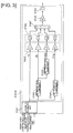
- FIG. 1 is a schematic system diagram of a vehicle controller according to a first embodiment.
- a vehicle comprises an engine 1 constituting a power source, brakes 20 for generating braking torque by applying frictional force to the wheels (brakes corresponding to individual wheels will be referred to hereafter as follows: front right brake: 20FR; front left brake: 20FL; rear right brake: 20RR; rear left brake: 20RL), and variable-damping-force shock absorbers 3 provided between each of the wheels and the vehicle body (“shock absorber” will be abbreviated "S/A” in the following description; shock absorbers corresponding to individual wheels will be referred to as follows: front right S/A: 3FR; front left S/A: 3FL; rear right S/A: 3RR; rear left S/A: 3RL).
- An engine 1 comprises an engine controller 1a (also referred to hereafter as an engine control unit; equivalent to motive power source control means) for controlling the torque outputted by the engine 1; the engine controller 1a controls the engine operation state (engine rpm, engine output torque, etc.) as desired by controlling the opening of the throttle valve, the fuel injection level, the ignition timing, and the like of the engine 1.
- the brakes 20 generate braking torque on the basis of hydraulic pressure supplied from a brake control unit 2 capable of controlling brake hydraulic pressure for each of the wheels according to driving state.
- the brake control unit 2 comprises a brake controller 2a (also referred to hereafter as a brake control unit) for controlling the braking torque generated by the brakes 20; the desired hydraulic pressure is generated in the brakes 20 for each of the wheels by the opening and closing of a plurality of solenoid valves using master cylinder pressure generated by a driver operating the brake pedal or pump pressure generated by a built-in motor-driven pump as a hydraulic pressure source.
- a brake controller 2a also referred to hereafter as a brake control unit
- the S/A 3 are damping force-generating devices for damping the elastic motion of coil springs provided between the unsprung mass (the axles, wheels, etc.) and the sprung mass (vehicle body, etc.) of the vehicle, and the damping force generated thereby can be adjusted by the operation of actuators.
- Each of the S/As 3 comprises a cylinder in which fluid is sealed, a piston that makes strokes within the cylinder, and an orifice for controlling the movement of the fluid between fluid chambers formed above and below the piston. Orifices of various diameters are formed in the piston, and an orifice corresponding to a control command is selected from the various orifices when the S/A actuator operates. Damping force corresponding to the diameter of the orifice is thereby generated. The movement of the piston will be more easily restricted if the orifice diameter is small, increasing damping force, and movement of the piston will be less easily restricted if the orifice diameter is large, decreasing damping force.
- damping force may also be set, for example, by disposing a solenoid control valve over a passage linking the fluid chambers formed above and below the piston and controlling the opening and closing of the solenoid control valve; the invention is not particularly limited with respect to this point.
- Each of the S/As 3 comprises an S/A controller 3a (equivalent to damping force control means) for controlling the damping force of the S/A 3, and damping force is controlled by the operating of the orifice diameter by the S/A actuator.
- wheel speed sensors 5 for detecting the wheel speed of each of the wheels (the sensors will be referred to as follows when wheel speeds corresponding to individual wheels are indicated: front right wheel speed: 5FR; front left wheel speed 5FL; rear right wheel speed: 5RR; rear left wheel speed: 5RL), an integrated sensor 6 for detecting forward/reverse acceleration, yaw rate, and lateral acceleration acting upon the center of gravity of the vehicle, a steering angle sensor 7 for detecting a steering angle indicating the amount to which the driver has operated the steering wheel, a vehicle speed sensor 8 for detecting vehicle speed, an engine torque sensor 9 for detecting engine torque, an engine rpm sensor 10 for detecting engine rpm, a master pressure sensor 11 for detecting master cylinder pressure, a brake switch 12 for outputting an on state signal when a brake pedal is operated, and an accelerator opening sensor 13 for detecting the degree to which an accelerator pedal is open.
- an integrated sensor 6 for detecting forward/reverse acceleration, yaw rate, and lateral acceleration acting upon the center of gravity of the vehicle
- the integrated sensor 6 may be disposed at the center of gravity of the vehicle or at another location without restriction as long as the sensor is capable of estimating various values at the position of the center of gravity.
- the sensor need not be integrated; individual sensors for detecting yaw rate, forward/reverse acceleration, and lateral acceleration may also be provided.
- FIG. 2 is a control block diagram showing a configuration of control performed by the vehicle controller according to the first embodiment.
- the first embodiment comprises three controllers: the engine controller 1a, the brake controller 2a, and the S/A controller 3a.
- the S/A controller 3a comprises a driver input control unit 31 for performing driver input control so that a desired vehicle orientation is attained on the basis of driver operations (of the steering wheel, accelerator and brake pedals, etc.), a driving state estimator unit 32 for estimating driving state on the basis of values detected by the sensors, a sprung mass vibration damping control unit 33 for controlling the vibrational state of the sprung mass of the vehicle on the basis of the estimated driving state, an unsprung mass vibration damping control unit 34 for controlling the vibrational state of the unsprung mass of the vehicle on the basis of the estimated driving state, and a damping force control unit 35 for deciding upon the damping force to be set for the S/As 3 on the basis of a shock absorber orientation control amount outputted from the driver input control unit 31, a sprung mass vibration
- the damping force control unit 35 may be provided separately from the S/A controller 3a as an orientation controller for a total of four S/A controllers including the damping force control unit 35, or all the controllers may be combined into a single integrated controller.
- the configuration of the first embodiment envisions the repurposing of an engine controller and a brake controller in an existing vehicle as an engine control unit 1a and a brake control unit 2a, and the installation of a separate S/A controller 3a to create the vehicle controller according to the first embodiment.
- Three actuators are used in the vehicle controller according to the first embodiment in order to control the vibrational state of the sprung mass of the vehicle. Because the control performed by each of the activators affects the state of the sprung mass of the vehicle, interference is a problem.
- the elements controllable by the engine 1, the elements controllable by the brakes 20, and the elements controllable by the S/As 3 all differ, and the matter of the combinations in which these elements should be controlled is another problem.
- the brakes 20 are capable of controlling bouncing motion and pitching motion, but controlling both at the same time will create a strong sense of deceleration and tend to create an unnatural feel for the driver.
- the S/As 3 are capable of absorbing rolling motion, bouncing motion, and pitching motion, but controlling all three of these using the S/As 3 will lead to increased manufacturing costs for the S/As 3, and tends to increase damping force; this facilitates high-frequency vibrational input from the road surface, also creating an unnatural feel for the driver.
- a trade-off must be made in that control performed by the brakes 20 will not lead to worse high-frequency vibration but will lead to an increased sense of deceleration, and control performed by the S/As 3 will not create a sense of deceleration but will lead to high-frequency vibrational input.
- the driver input control unit 31 comprises an engine driver input control unit 31a for attaining the vehicle orientation demanded by the driver by controlling the torque of the engine 1, and an S/A driver input control unit 31b for attaining the vehicle orientation demanded by the driver by controlling the damping force of the S/As 3.
- the engine driver input control unit 31a calculates a ground load variation minimization control amount for minimizing variations in the ground loads of the front wheels and the rear wheels, and a yaw response control amount corresponding to the vehicle behavior desired by the driver on the basis of signals from the steering angle sensor 7 and the vehicle speed sensor 8.
- the S/A driver input control unit 31b calculates a driver input damping force control amount corresponding to the vehicle behavior desired by the driver on the basis of the signals from the steering angle sensor 7 and the vehicle speed sensor 8, and outputs this amount to the damping force control unit 35. If, for example, the nose of the vehicle rises while the driver is turning, the driver's field of view can easily be taken off the road; in such cases, the damping force of the four wheels is outputted as the driver input damping force control amount so as to prevent the nose from rising. A driver input damping force control amount for minimizing rolling generating during turning is also outputted.
- FIG. 3 is a control block diagram showing a configuration of roll rate minimization control according to the first embodiment.
- a lateral acceleration estimator unit 31b1 estimates lateral acceleration Yg on the basis of a front wheel steering angle ⁇ f detected by the steering angle sensor 7, a rear wheel steering angle ( ⁇ r (the actual rear wheel steering angle if a rear wheel steering device is provided; otherwise, 0 as appropriate), and a vehicle speed VSP detected by the vehicle speed sensor 8.
- the lateral acceleration Yg is calculated according to the following formula using an estimated yaw rate value ⁇ .
- Yg VSp ⁇ ⁇
- a 90° phase lead component-generating unit 31b2 differentiates the estimated lateral acceleration Yg and outputs a lateral acceleration derivative dYg.
- a 90° phase lag component-generating unit 31b3 outputs a component F(dYg) in which the phase of the lateral acceleration derivative dYg is delayed 90°.
- the component F(dYg) 90° the phase of the component from which the low-frequency region has been removed generated by the phase lead component-generated unit 31b2 is returned to the phase of the lateral acceleration Yg, and the DC is cut from the lateral acceleration Yg; i.e., the component is a transitional component of lateral acceleration Yg.
- a 90° phase lag component-generating unit 31b4 outputs a component F(Yg) in which the phase of the lateral acceleration Yg is delayed 90°.
- a gain multiplier unit 31b5 multiplies the lateral acceleration Yg, lateral acceleration derivative dYg, lateral acceleration DC-cut component F(dYg), and 90° phase lag component F(Yg) by gain. Gain is set according to the roll rate transfer function for the steering angle. Gain may also be adjusted according to four control modes described hereafter.
- a square calculator unit 31b6 squares and outputs the components having been multiplied by gain.
- a synthesizer unit 31b7 adds the values outputted by the squaring processor unit 31b6.
- a gain multiplier unit 31b8 multiplies the square of the summed components by gain, and outputs the results.
- a square root calculator unit 31 b9 calculates the square root of the value outputted by the gain multiplier unit 31b7, thereby calculating a driver input orientation control amount for use in roll rate minimization control, and outputs the amount to the damping force control unit 35.
- the 90° phase lead component-generating unit 31b2, 90° phase lag component-generating unit 31b3, 90° phase lag component-generating unit 31b4, gain multiplier unit 31b5, square calculator unit 31b6, synthesizer unit 31b7, gain multiplier unit 31b8, and square root calculator unit 31b9 constitute a Hilbert transform unit 31b10 for generating an envelope waveform using a Hilbert transform.
- Figure 4 is a time chart showing an envelope waveform formation process performed in the roll rate minimization control of the first embodiment.
- a roll rate gradually begins to be generated.
- the 90° phase lead component dYg is added to form an envelope waveform, and the driver input orientation control amount is calculated on the basis of the envelope waveform-based scalar quantity, thereby allowing roll rate generation during the initial stage of steering to be minimized.
- the addition of the lateral acceleration DC-cut component F(dYg) to form the envelope waveform allows roll rates generated during transitional states, such as when the driver is beginning or ending steering, to be efficiently minimized. In other words, damping force is not excessively increased and degradation in ride comfort can be avoided during constant turning states in which roll is stably generated.
- the 90° phase lead component dYG and the lateral acceleration DC-cut component F(dYg) disappear, and the 90° phase lag component F(Yg) is then added.
- a roll rate resonance component equivalent to the roll aftershock is generated after rolling occurs, even if there is little change in the roll rate itself in a steady steering state.
- damping force would be set to a low value from time t2 to time t3, risking destabilization of vehicle behavior by the roll rate resonance component.
- the 90° phase lag component F(Yg) is added in order to minimize the roll rate resonance component.
- FIG. 5 is a control block diagram showing the configuration of a driving state estimator unit of the first embodiment.
- the driving state estimator unit 32 of the first embodiment calculates a stroke speed, bounce rate, roll rate, and pitch rate for each wheel used in the skyhook control performed by the sprung mass vibration damping control unit 33 as described hereafter primarily on the basis of the wheel speeds detected by the wheel speed sensors 5.
- the values from the wheel speed sensors 5 of the wheels are inputted into a stroke speed calculator unit 321, and sprung mass speed is calculated by the stroke speed calculator unit 321 from the stroke speeds calculated for the wheels.
- Figure 6 is a control block diagram showing the specifics of control in a stroke speed calculator unit of the first embodiment.
- a stroke speed calculator unit 321 is separately provided for each wheel; the control block diagram shown in Figure 6 focuses on a specific wheel.
- the stroke speed calculator unit 321 comprises a reference wheel speed calculator unit 300 for calculating a reference wheel speed on the basis of the values from the wheel speed sensors 5, the front wheel steering angle ⁇ f detected by the steering angle sensor 7, a rear wheel steering angle ⁇ r (the actual rear wheel steering angle if a rear wheel steering device is provided, 0 otherwise), a vehicle body lateral speed, and an actual yaw rate detected by the integrated sensor 6, a tire rotational vibration frequency calculator unit 321a for calculating tire rotational vibration frequency on the basis of the calculated reference wheel speed, a deviation calculator unit 321b for calculating the deviation between the reference wheel speed and the value from the wheel speed sensor (i.e., wheel speed variation), a GEO conversion unit 321c for converting the deviation calculated by the deviation calculator unit 321
- FIG. 7 is a block diagram showing the configuration of a reference wheel speed calculator unit of the first embodiment.
- the reference wheel speed is a wheel speed from which various types of interference from the individual wheels have been removed.
- the difference between the value from the wheel speed sensor and the reference wheel speed is related to a component that varies according to a stroke generated by vehicle body bouncing motion, rolling motion, pitching motion, or unsprung vertical vibration; in the present embodiment, the stroke speed is calculated on the basis of this difference.
- a flat surface motion component extractor unit 301 uses the wheel speed sensor values as inputs to calculate a first wheel speed V0 as a reference wheel speed for each of the wheels on the basis of the vehicle body plan view model.
- ⁇ (rad/s) is the wheel speed sensor detected by the wheel speed sensor 5
- ⁇ f (rad) is a front wheel actual steering angle detected by the steering angle sensor 7
- ⁇ r (rad) is a rear wheel actual steering angle
- Vx is vehicle body lateral speed
- ⁇ (rad/s) is the yaw rate detected by the integrated sensor 6
- V (m/s) is a vehicle body speed estimated from the calculated reference wheel speed ⁇
- VFL, VFR, VRL, and VRR are the reference wheel speeds to be calculated
- Tf is a front wheel treat
- Tr is a rear wheel treat
- Lf is the distance from the position of the vehicle center of gravity to the front wheels
- Lr is the distance from the position of the vehicle center of gravity to the rear wheel.
- VFL V - Tf / 2 ⁇ ⁇ cos ⁇ ⁇ f + Vx + Lf ⁇ ⁇ ⁇ sin ⁇ ⁇ f
- VFR V + Tf / 2 ⁇ ⁇ cos ⁇ ⁇ f + Vx + Lf ⁇ ⁇ ⁇ sin ⁇ ⁇ f
- VRL V - Tr / 2 ⁇ ⁇ cos ⁇ ⁇ r + Vx - Lr ⁇ ⁇ ⁇ sin ⁇ ⁇ r
- VRR V + Tr / 2 ⁇ ⁇ cos ⁇ ⁇ r + Vx - Lr ⁇ ⁇ ⁇ sin ⁇ ⁇ r
- V is written as V0FL, V0FR, V0RL, and V0RR (equivalent to first wheel speeds) as values corresponding to the various wheels.
- a roll interference -removing unit 302 uses the first wheel speed V0 as an input to calculate second wheel speeds V0F, V0R as reference wheel speeds for the front and rear wheels on the basis of a vehicle body front view model.
- the vehicle body front view model is used to remove wheel speed differences generated by rolling motion occurring around a center of roll rotation on a normal line passing through the vehicle center of gravity as viewed from the front of the vehicle, and is represented as follows.
- V ⁇ 0 ⁇ F V ⁇ 0 ⁇ FL + V ⁇ 0 ⁇ FR / 2
- V ⁇ 0 ⁇ R V ⁇ 0 ⁇ RL + V ⁇ 0 ⁇ RR / 2
- a pitch interference-removing unit 303 uses the second wheel speeds V0F, V0R as inputs to calculate third wheel speeds VbFL, VbFR, VbRL, and VbRR constituting reference wheel speeds for all the wheels according to a vehicle body side view model.
- the vehicle body side view model is used to remove wheel speed differences generated by pitching motion occurring around a center of pitch rotation on a normal line passing through the vehicle center of gravity as viewed from the side of the vehicle.
- the deviation between the reference wheel speed ⁇ 0 and the wheel speed sensor value is calculated; the deviation represents a wheel speed variation arising from suspension strokes, and is therefore converted into a stroke speed Vzs.
- the wheel rotational centers move forwards and backwards as strokes occur, and the axles equipped with the wheel speed sensors 5 become tilted, creating a difference in rotational angle with the wheels. Because this forward and backward motion leads to changes in wheel speed, deviations between the reference wheel speed and the wheel speed sensor value can be extracted as stroke-induced variations.
- the degree of variation that occurs can be set, as appropriate, according to the suspension geometry.
- a sprung mass speed calculator unit 322 calculates a bounce rate, roll rate, and pitch rate for use in skyhook control.
- Figure 8 is a schematic diagram of a vehicle body vibration model.
- Figure 8(a) is a model for a vehicle provided with S/As of constant damping force (hereafter referred to as a conventional vehicle)
- Figure 8(b) is a model for a vehicle provided with variable S/As in which skyhook control is performed.
- Ms indicates sprung mass
- Mu indicates unsprung mass
- Ks indicates coil spring modulus of elasticity
- Cs indicates S/A damping coefficient
- Ku indicates unsprung (tire) modulus of elasticity
- Cu indicates unsprung (tire) damping coefficient
- Cv indicates a variable damping coefficient.
- z2 indicates the position of the sprung mass
- z1 indicates the position of the unsprung mass
- z0 indicates the position of the road surface.
- dz2 - dz1 is stroke speed (Vz_sFL, Vz_sFR, Vz_sRL, Vz_sRR)
- the sprung mass speed can be calculated from the stroke speed.
- adjusting damping force via skyhook control will vastly reduce estimation precision, creating the problem that a large orientation control force (damping force adjustment) cannot be applied in the conventional vehicle model.
- Cv is a discontinuous value
- the variables are equivalent to filter coefficients, and a variable damping coefficient Cv that is discontinuous in the pseudo-differential term ⁇ (Cs + Cv) ⁇ s + Ks ⁇ ; thus, filter response is unstable, and suitable estimation precision cannot be obtained. In particular, unstable filter response will lead to phase shifting. Skyhook control cannot be achieved if the correspondence between the phase and the sign for sprung mass speed breaks down. The decision was thus made to estimate sprung mass speed using an active skyhook model, in which a stable Csky can be directly used without relying upon the sign relationship between sprung mass speed and the stroke speed even if semi-active S/As 3 are used.
- dz ⁇ 2 - 1 / s ⁇ 1 / s + Csky / Ms ⁇ Cs / Ms ⁇ s + Ks / Ms ⁇ dz ⁇ 2 - dz ⁇ 1
- xsB as the bounce term of the stroke amount
- xsR as the roll term
- xsP as the pitch term
- xsW as the warp term
- z_sFL, z_sFR, z_sRL, z_sRR as stroke amounts corresponding to Vz_sFL, Vz_sFR, Vz_sRL, Vz_sRR
- z_sFL z_sFR z_sRL z_sRR 1 1 - 1 - 1 1 - 1 - 1 1 1 1 1 1 1 1 - 1 1 - 1 xsB xsR xsP xsW ⁇ 1 1 - 1 - 1 - 1 1 - 1 - 1 1 1 1 1 1 - 1 1 - 1 - 1 z_sFL z_sFR z_sRL z_sRR
- the differentials dxsB,... of xsB, xsR, xsP, xsW are expressed by the following formulas.
- the state of the sprung mass of an actual vehicle can be estimated on the basis of the stroke speeds for the various wheels.
- the sprung mass vibration damping control unit 33 comprises a skyhook control unit 33a for controlling orientation according to the estimated value for sprung mass speed described above, and a frequency-sensitive control unit 33b for minimizing sprung mass vibration on the basis of the road surface input frequency.
- the vehicle controller comprises three actuators for achieving sprung mass orientation control in the form of the engine 1, the brakes 20, and the S/As 3.
- bounce rate, roll rate, and pitch rate are the objects of control for the S/As 3
- bounce rate and pitch rate are the objects of control for the engine 1
- pitch rate is the object of control for the brakes 20 in the skyhook control unit 33a.
- a shared control amount must be used for each.
- the control amount for each of the actuators can be determined by using the sprung mass speed estimated by the driving state estimator unit 32.
- FB is sent to the engine 1 and the S/As 3 as the bounce orientation control amount.
- FR is for control performed only by the S/As 3, and so is sent to the damping force control unit 35 as a roll orientation control amount.
- Pitch control is performed by the engine 1, the brakes 20, and the S/As 3.
- FIG. 9 is a control block diagram of actuator control amount calculation processes performed during pitch control in the first embodiment.
- the skyhook control unit 33a comprises a first target orientation control amount calculator unit 331 for calculating a target pitch rate constituting a first target orientation control amount that is a control amount that can used in common for all of the actuators, an engine orientation control amount calculator unit 332 for calculating the engine orientation control amount achieved by the engine 1, a brake orientation control amount calculator unit 334 for calculating the brake orientation control amount achieved by the brakes 20, and an S/A orientation control amount calculator unit 336 for calculating the S/A orientation control amount achieved by the S/As 3.
- a first target orientation control amount calculator unit 331 for calculating a target pitch rate constituting a first target orientation control amount that is a control amount that can used in common for all of the actuators
- an engine orientation control amount calculator unit 332 for calculating the engine orientation control amount achieved by the engine 1
- a brake orientation control amount calculator unit 334 for calculating the brake orientation control amount achieved by the brakes 20
- the first target orientation control amount calculator unit 331 outputs pitch rate without further modification (hereafter, this pitch rate will be referred to as the first target orientation control amount).
- the engine orientation control amount calculator unit 332 calculates the engine orientation control amount, which is the control amount achievable by the engine 1, on the basis of the inputted first target orientation control amount.
- a limit value that limits the engine torque control amount according to the engine orientation control amount so as not to create an unnatural feel for the driver is set in the engine orientation control amount calculator unit 332.
- the engine torque control amount is thus kept within a predetermined forward/reverse acceleration range when converted to forward/reverse acceleration. Accordingly, when the engine torque control amount is calculated on the basis of the first target orientation control amount and results in a value that is equal to or greater than the limit value, a skyhook control amount for the pitch rate attainable using the limit value (i.e., the product of the pitch rate minimized by the engine 1 multiplied by CskyP; hereafter, "engine orientation control amount”) is outputted.
- a value converted to the pitch rate by a converter unit 332a is outputted to a second target orientation control amount calculator unit 333, to be described hereafter.
- the engine control unit 1a calculates the engine torque control amount on the basis of the engine orientation control amount corresponding to the limit value, and outputs this amount to the engine 1.
- the second target orientation control amount calculator unit 333 calculates the difference between the first target orientation control amount and the value of the engine orientation control amount converted to pitch rate by the converter unit 332a, and outputs this difference to the brake orientation control amount calculator unit 334.
- the braking torque control amount is thus kept within a predetermined forward/reverse acceleration range when converted to forward/reverse acceleration (with the limit value being calculated on the basis of naturalness of ride feel for passengers, actuator lifespan, etc.). Accordingly, when the brake orientation control amount is calculated based on the second target orientation control amount, and the calculated value is equal to or greater than the limit value, a pitch rate minimization amount (hereafter, "brake orientation control amount") achievable by such a limit value is outputted. At this time, a value converted to the pitch rate by a converter unit 3344 is outputted to a third target orientation control amount calculator unit 335, to be described hereafter. In addition, the brake control unit 2a calculates a braking torque control amount (or deceleration) on the basis of the brake orientation control amount corresponding to the limit value, and is outputted to the brake control unit 2.
- the third target orientation control amount calculator unit 335 calculates a third target orientation control amount constituted by the difference between the second target orientation control amount and the brake orientation control amount, and outputs this amount to the S/A orientation control amount calculator unit 336.
- the S/A orientation control amount calculator unit 336 outputs a pitch orientation control amount corresponding to the third target orientation control amount.
- the damping force control unit 35 calculates the damping force control amount on the basis of the bounce orientation control amount, the roll orientation control amount, and the pitch orientation control amount (hereafter collectively referred to as the S/A orientation control amounts), and outputs this amount to the S/As 3.
- the brakes 20 are capable of controlling both bounce and pitch; thus, it is preferable that they control both.
- bounce control is performed by the brakes 20
- braking force is applied to all four wheels simultaneously, and there is a strong sense of deceleration even in directions of low control priority despite the difficulty in obtaining control effects, tending to create an unnatural feed for the driver.
- Figure 10 is a control block diagram of brake pitch control in the first embodiment.
- m mass of the vehicle body
- Bff front wheel braking force
- BFr rear wheel braking force
- Hcg height between the vehicle center of gravity and the road surface
- a vehicle acceleration
- Mp pitch moment
- Vp pitch rate
- the brake orientation control amount calculator unit 334 comprises the following control blocks on the basis of the relationship described above.
- a dead band process sign determiner unit 3341 determines the sign for the inputted pitch rate Vp; if the sign is positive, no control is necessary, so 0 is outputted to a deceleration sense-reducing processor 3342, and if the sign is negative, control is determined to be possible, so a pitch rate signal is outputted to the deceleration sense-reducing processor 3342.
- a deceleration sense reduction process corresponds to the limit applied by the limit value set in the brake orientation control amount calculator unit 334.
- a squaring processor 3342a squares the pitch rate signal. This reverses the sign, and smoothes the increase in control force.
- a pitch rate square damping moment calculator unit 3342b multiplies the squared pitch rate by a skyhook gain CskyP for the pitch term that takes the squaring process into account to calculate pitch moment Mp.
- a target deceleration calculator unit 3342c divides the pitch moment Mp by mass m and the Height Hcg between the vehicle center of gravity and the road surface to calculate a target deceleration.
- a jerk threshold value limiter unit 3342d determines whether the rate of change in the calculated target deceleration, i.e., jerk, is within preset deceleration jerk threshold value and release jerk threshold value ranges, and whether the target deceleration is within a forward/reverse acceleration limit value range. If any of the threshold values is exceeds, the target deceleration is corrected to a value within the ranges for the jerk threshold values. If the target deceleration exceeds the limit value, it is set to within the limit value. It is thereby possible to generate deceleration so as not to create an unnatural feel for the driver.
- a target pitch moment converter unit 3343 multiplies the target deceleration limited by the jerk threshold value limiter unit 3342d by the mass m and the height Hc9 to calculate a target pitch moment, which is outputted to the brake control unit 2a and a target pitch rate converter unit 3344.
- the target pitch rate converter unit 3344 divides the target pitch moment by the pitch term skyhook gain CskyP to convert to a target pitch rate (equivalent to a brake orientation control amount), which is outputted to a third target orientation control amount calculator unit 335.
- the first target orientation control amount is calculated, the engine orientation control amount is next calculated, the brake orientation control amount is calculated from the second target orientation control amount constituted by the difference between the first target orientation control amount and the engine orientation control amount, and the S/A orientation control amount is calculated from the third target orientation control amount constituted by the difference between the second orientation control amount and the brake orientation control amount. It is thereby possible to reduce the amount of pitch rate control performed by the S/As 3 by the control performed by the engine 1 and the brakes 20, thus allowing for a relative reduction in the controllable range of the S/As 3, and sprung mass orientation control to be achieved using inexpensive S/As 3.
- the sprung mass speed is estimated on the basis of the values detected by the wheel speed sensors 5, and skyhook control is performed based thereon, thereby achieving sprung mass vibration damping control.
- a comfortable driving state i.e., a soft ride rather than a feeling of vehicle body flatness
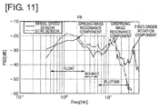
- Figure 11 is a graph simultaneously showing a wheel speed frequency profile detected by a wheel speed sensor and a stroke frequency profile from a stroke sensor not installed in the present embodiment.
- frequency profile refers to a profile in which the magnitude of amplitude against frequency is plotted on the y axis.
- a comparison of the frequency component of the wheel speed sensor 5 and the frequency component of the stroke sensor shows that roughly similar scalar quantities can be plotted from the sprung mass resonance frequency component to the unsprung mass resonance frequency component.
- the damping force has been set on the basis of this frequency profile out of the values detected by the wheel speed sensor 5.
- the region in which the sprung mass resonance frequency component is present is a frequency region in which the swaying of a passenger's entire body creates a sensation as thought the passenger is floating in the air, that is, that the gravitational acceleration affecting the passenger has decreased, and is referred to as the float region (0.5-3 Hz).
- the region between the sprung mass resonance frequency component and the unsprung mass resonance frequency component is a frequency region in which, although there is no sensation of reduced gravitational acceleration, there is a sensation similar to the quick, frequent bouncing experienced by a person on horseback when riding at a trot, that is, an up-and-down motion followed by the entire body, and is referred to as the bounce region (3-6 Hz).
- the region in which the unsprung mass resonance frequency component is present is a frequency region in which, although vertical body mass movement is not experienced, frequent vibrations are conveyed to a part a passenger's body, such as the thighs, and is referred to as a flutter region (6-23 Hz).
- FIG. 12 is a control block diagram showing frequency-sensitive control in sprung mass vibration damping control in the first embodiment.
- a band elimination filter 350 cuts out noise apart from the frequency component in the wheel speed sensor value that is used to perform control.
- a predetermined frequency region splitter unit 351 splits the frequency component into a float region, a bounce region, and a flutter region.
- a Hilbert transform processor unit 352 performs a Hilbert transform upon the split frequency bands, converting them to scalar quantities (specifically, areas calculated using amplitude and frequency band) based on the amplitude of the frequency.
- a vehicle vibrational system weight-setting unit 353 sets weights for the vibration from the float region, bounce region, and flutter region frequency bands that is actually propagated to the vehicle.
- a human sensation weight-setting unit 354 sets weights for the vibration from the float region, bounce region, and flutter region frequency bands that is actually propagated to a passenger.
- Figure 13 is a correlation graph showing human sense profiles plotted against frequency.
- passenger sensitivity to frequencies is comparatively low in the low-frequency float region, with sensitivity gradually increasing as one moves into regions of higher frequencies. Frequencies in the flutter region and higher-frequency regions become progressively harder to transmit to the passenger.
- the float region human sensation weight Wf is set at 0.17
- the bounce region human sensation weight Wh is set higher than Wf at 0.34
- the flutter region human sensation weight Wb is set higher than Wf and Wh at 0.38. It is thereby possible to increase the correlation between the scalar quantities for the various frequency bands and the vibration actually propagated to a passenger.
- These two weighting factors may be altered, as appropriate, according to vehicle concept or passenger preferences.
- a weight-determining means 355 calculates the proportions occupied by the weight for each of the frequency bands. Defining a as the float region weight, b as the bounce region weight, and c as the flutter region weight, the weighting factor for the float region is (a/(a + b + c)), the weighting factor for the bounce region is (b/(a + b + c)), and the weighting factor for the flutter region is (c/(a + b + c)).
- a scalar quantity calculator unit 356 multiplies the scalar quantities for the various frequency bands calculated by the Hilbert transform processor unit 352 by the means 355, and outputs final scalar quantities. The process up to this point is performed on the wheel speed sensor values for each of the wheels.
- a maximum value-selecting unit 357 selects the maximum value out of the final scalar quantities calculated for each of the four wheels. The 0.01 at the bottom is set to avoid having 0 as a denominator, as the total of the maximum values is used as a denominator in a subsequent process.
- a proportion calculator unit 358 calculates proportions using the total of the maximum scalar quantity values for each of the frequency bands as the denominator and the maximum scalar quantity value for the frequency band equivalent to a float region as the numerator. In other words, the proportion of contamination (hereafter, simply "proportion") in the float region contained in all vibration components is calculated.
- a sprung mass resonance filter 359 performs a filter process having a sprung mass resonance frequency of roughly 1.2 Hz on the calculated proportion, and extracts a sprung mass resonance frequency band component representing the float region from the calculated proportion. In other words, because the float region is present at roughly 1.2 Hz, it is believed that the proportion of this region will also vary around 1.2 Hz.
- the finally extracted proportion is then outputted to the damping force control unit 35, and a frequency-sensitive damping force control amount corresponding to the proportion is outputted.
- Figure 14 is a plot showing the relationship between the proportion of vibration contamination and damping force in a float region in the frequency-sensitive control of the first embodiment.
- a high damping force is set when the float region occupies a large proportion, thereby reducing the vibration level of sprung mass resonance. Even if a high damping force is set, no high-frequency vibration or bounce-like vibration is transmitted to the passenger because the bounce region and flutter region occupy small proportions. Meanwhile, setting a low damping force when the float region occupies a small proportion reduces the vibration transmission profile at and above sprung mass resonance, minimizing high-frequency vibration and yielding a smooth ride.
- Figure 15 is a wheel speed frequency profile detected by a wheel speed sensor 5 in certain driving conditions. This profile especially appears when driving on road surfaces having continuous small bumps, such as cobbled roads.
- skyhook control is performed while driving on a road surface exhibiting this profile, the problem arises that, because damping force is determined using the peak amplitude value in skyhook control, any degradation in phase estimation for high-frequency vibrational input will cause an extremely high damping force to be set at the wrong timing, leading to exacerbated high-frequency vibration.
- a resonance frequency band is also present in tires, as they possess both a modulus of elasticity and a damping coefficient.
- the band is present toward frequencies higher than sprung mass resonance.
- the unsprung mass resonance component causes tire rumbling in the unsprung mass, potentially degrading ground contact.
- rumbling in the unsprung mass can be uncomfortable for passengers.
- damping force is set according to the unsprung mass resonance component in order to minimize unsprung mass resonance-induced rumbling.
- FIG 16 is a block diagram showing a control configuration for unsprung mass vibration damping control in the first embodiment.
- An unsprung mass resonance component extractor unit 341 applies a band-pass filter to the wheel speed variation outputted from the deviation calculator unit 321b of the driving state estimator unit 32 to extract an unsprung mass resonance component.
- the unsprung mass resonance component is extracted from the region at roughly 10-20 Hz in the wheel speed frequency component.
- An envelope waveform-forming unit 342 scalarizes the extracted unsprung mass resonance component, and forms an envelope waveform using an envelope filter.
- a gain multiplier unit 343 multiplies the scalarized unsprung mass resonance component by the gain, calculates an unsprung mass vibration damping force control amount, which is outputted to the damping force control unit 35.
- an unsprung mass resonance component is extracted by applying a band-pass filter to the wheel speed variation outputted from the deviation calculator unit 321b of the driving state estimator unit 32, but it is also acceptable to apply a band-pass filter to the value detected by the wheel speed sensor to extract the unsprung mass resonance component, or for the driving state estimator unit 32 to estimate the unsprung mass speed along with the sprung mass speed to extract an unsprung mass resonance component.
- FIG. 17 is a control block diagram showing a control configuration for a damping force control unit of the first embodiment.
- the driver input damping force control amount outputted from the driver input control unit 31, the S/A orientation control amount outputted from the skyhook control unit 33a, the frequency-sensitive damping force control amount outputted from the frequency-sensitive control unit 33b, the unsprung mass vibration damping force control amount outputted from the unsprung mass vibration damping control unit 34, and the stroke speed calculated by the driving state estimator unit 32 are inputted into an equivalent viscous damping coefficient converter unit 35a, which converts these values into an equivalent viscous damping coefficient.
- a damping coefficient-reconciling unit 35b reconciles which damping coefficient, out of the damping coefficients converted by the equivalent viscous damping coefficient converter unit 35a (hereafter referred to individually as the driver input damping coefficient k1, the S/A orientation damping coefficient k2, the frequency-sensitive damping coefficient k3, and the unsprung mass vibration damping coefficient k4), is used to perform control, and outputs a final damping coefficient.
- a control signal converter unit 35c converts a control signal (commanded current value) to be sent to the S/As 3 on the basis of the damping coefficient reconciled by the damping coefficient-reconciling unit 35b and the stroke speed, and outputs the signal to the S/As 3.
- the vehicle controller of the first embodiment has four control modes.
- the first mode is standard mode, for situations in which suitable steering conditions are obtainable while driving on general urban roads.
- the second mode is sports mode, for situations in which stable steering conditions are available while aggressively driving along winding roads and the like.
- the third mode is comfort mode, for situations in which priority is given to comfort while driving, such as when starting off at low vehicle speeds.
- the fourth mode is highway mode, for situations involving driving at high vehicle speeds on highways and the like with multiple straight sections.
- skyhook control is performed by the skyhook control unit 33a and unsprung mass vibration damping control is performed by the unsprung mass vibration damping control unit 34 while giving priority to driver input control performed by the driver input control unit 31.
- control amount for the unsprung mass vibration damping control performed by the unsprung mass vibration damping control unit 34 is added to the skyhook control performed by the skyhook control unit 33a while given priority to the driver input control performed by the driver input control unit 31.
- Figure 18 is a flow chart of a damping coefficient reconciliation process performed during a standard mode in the first embodiment.
- step S1 it is determined whether the S/A orientation damping coefficient k2 is greater than the unsprung mass vibration damping coefficient k4, and, if so, the process continues to step S4, and k2 is set as the damping coefficient.
- step S2 the scalar quantity proportion of the flutter region is calculated on the basis of the scalar quantities for the float region, bounce region, and flutter region described in the context of the frequency-sensitive control unit 33b.
- step S3 it is determined whether the proportion of the flutter region is equal to or greater than a predetermined value, and, if so, the process continues to step S4 and the low value k2 is set as the damping coefficient for fear of high-frequency vibration reducing ride comfort.
- the proportion of the flutter region is less than the predetermined value, there is no worry of high-frequency vibration reducing ride comfort even if a high damping coefficient is set, so the process continues to step S5, and k4 is set as the coefficient.
- Figure 19 is a flow chart of a damping coefficient reconciliation process performed during a sports mode in the first embodiment.
- step S 12 it is determined whether a damping force distribution factor x is within a predetermined range (greater than ⁇ and less than ⁇ ), and, if so, distribution is determined to be roughly equal for all the wheels, and the process continues to step S13; if even one factor is outside the predetermined range, the process continues to step S16.
- step S13 it is determined whether the unsprung mass vibration damping coefficient k4 is greater than the driver input damping coefficient k1, and, if so, the process continues to step S 15, and k4 is set as a first damping coefficient k. On the other hand, if the unsprung mass vibration damping coefficient k4 is equal to or less than the driver input damping coefficient k1, the process continues to step S14, and k1 is set as the first damping coefficient k.
- step S16 it is determined whether the unsprung mass vibration damping coefficient k4 is the maximum value max that can be set for the S/As 3; if so, the process continues to step S17, and, if not, the process continues to step S18.
- step S17 the maximum value for the driver input damping coefficients k1 for the four wheels is the unsprung mass vibration damping coefficient k4, and the damping coefficient that satisfies the damping force distribution factor is calculated as the first damping coefficient k. In other words, a value is calculated such that the damping coefficient is maximized while the damping force distribution factor is satisfied.
- step S18 a damping coefficient such that the damping force distribution factor is satisfied within a range in which the driver input damping coefficients k1 for all four wheels are equal to or greater than k4.
- a value is calculated such that the damping force distribution factor set by the driver input control is satisfied, and the requirements of unsprung mass vibration damping control are also met.
- step S 19 it is determined whether the first damping coefficients k set in the abovementioned steps are less than the S/A orientation damping coefficient k2 set during skyhook control; if so, k2 is set and the process continues to step S20 due to the damping coefficient required by skyhook control being larger. On the other hand, if k is equal to or greater than k2, k is set and the process continues to step S21.
- Figure 20 is a flow chart of a damping coefficient reconciliation process performed during a comfort mode in the first embodiment.
- step S30 it is determined whether the frequency-sensitive damping coefficient k3 is greater than the unsprung mass vibration damping coefficient k4, and, if so, the process continues to step S32 and the frequency-sensitive damping coefficient k3 is set. On the other hand, if the frequency-sensitive damping coefficient k3 is determined to be equal to or less than the unsprung mass vibration damping coefficient k4, the process continues to step S32 and the unsprung mass vibration damping coefficient k4 is set.
- comfort mode priority is given, as a rule, to unsprung mass resonance damping control, which minimizes resonance in the unsprung mass. Because frequency-sensitive control is performed as sprung mass vibration damping control to begin with, and an optimal damping coefficient for the road surface conditions is set, control can be performed while ensuring ride comfort, allowing sensations insufficient ground contact caused by rattling in the unsprung mass to be avoided through unsprung mass vibration damping control. In comfort mode, as in standard mode, it is acceptable for the damping coefficient to be switched according to the proportion of flutter in the frequency scalar quantity. This allows for a super comfort mode in which ride comfort is even better ensured.
- Figure 21 is a flow chart of a damping coefficient reconciliation process performed during a highway mode in the first embodiment.
- the same reconciliation process as in sports mode is performed from steps S11 to S18; thus, description thereof will be omitted.
- step S40 the S/A orientation damping coefficient k2 yielded by skyhook control is added to the reconciled first damping coefficient k yielded by the process up to step S18 and outputted.
- Figure 22 is a time chart showing changes in damping coefficient when driving on a hilly road surface and a bumpy road surface. For instance, if an attempt is made to minimize swaying motion in the vehicle body caused by the effects of slight hills in the road surface when driving at high vehicle speeds via skyhook control alone, it is necessary to detect slight variations in wheel speed, which requires that a comparatively high skyhook control gain be set. In such cases, swaying motion can be minimized, but bumps in the road surface can lead to the control gain being too great, creating the risk of excessive damping force control being performed. This gives rise to concerns of degraded ride comfort or vehicle body orientation.
- the first damping coefficient k is constantly set, as in highway mode, a certain level of damping force can be constantly ensured, allowing swaying motion in the vehicle body to be minimized even if a low damping coefficient is used in skyhook control.
- a low damping coefficient is used in skyhook control.
- bumps in the road surface can be managed using a normal control gain.
- skyhook control is performed in a state in which the damping coefficient k is set, a process of reducing the damping coefficient can be operated in a semi-active control region, unlike in the case of a damping coefficient limit, ensuring a stable vehicle orientation during high-speed driving.
- Figure 23 is a flow chart of a driving state-based mode selection process performed by a damping coefficient-reconciling unit of the first embodiment.
- step S50 it is determined whether the vehicle is driving straight ahead based on the value from the steering angle sensor 7; if so, the process continues to step S51, and if the vehicle is determined to be in a state of turning, the process continues to step S54.
- step S51 it is determined whether the vehicle speed is equal to or greater than a predetermined vehicle speed VSP1 indicating a state of high vehicle speed on the basis of the value from the vehicle speed sensor 8, and, if so, the process continues to step S52 and standard mode is selected. On the other hand, if the speed is less than VSP1, the process continues to step S53 and comfort mode is selected.
- VSP1 vehicle speed indicating a state of high vehicle speed
- standard mode is selected when driving at a high vehicle speed when driving straight ahead, thereby making it possible to stabilize the vehicle body orientation via skyhook control, ensure ride comfort by minimizing high-frequency vibration-induced bouncing or fluttering, and minimizing resonance in the unsprung mass.
- Selecting comfort mode when driving at low speeds makes it possible to minimize resonance in the unsprung mass while minimizing the transmission of vibration such as bouncing or fluttering to passengers.
- highway mode is selected when driving at a high vehicle speed in a state of turning, thereby performing control using a value to which a damping coefficient has been added; thus, high damping force is yielded as a rule. It is thus possible to minimize unsprung mass resonance while actively ensuring the unsprung mass resonance during turning via driver input control, even when traveling at a high vehicle speed. Selecting sports mode when driving at a low vehicle speed allows unsprung mass resonance to be minimized while actively ensuring the vehicle body orientation during turning via driver input control and performing skyhook control as appropriate, thereby allowing for driving with a stable vehicle orientation.
- the first embodiment yields the following effects.
- a value satisfying both the damping force distribution factor and the requirements of unsprung vibration damping control is calculated when the vehicle is in a turning driving state, enabling vibration damping control of the unsprung mass while maintaining a stable vehicle body orientation when the vehicle is in a turning driving state.
Claims (7)
- Dispositif de commande de véhicule caractérisé en ce qu'il comprend :un amortisseur de chocs à force d'amortissement variable (3) ayant une force d'amortissement réglable ;un moyen de commande d'amortissement de vibration de masse suspendue (33) pour calculer une quantité de commande d'amortissement de vibration de masse suspendue constituant une force d'amortissement pour minimiser la vibration d'une masse suspendue ;un moyen de commande d'amortissement de vibration de masse non suspendue (34) pour calculer une quantité de commande d'amortissement de vibration de masse non suspendue constituant une force d'amortissement pour minimiser la vibration d'une masse non suspendue ;un moyen de détermination d'état de conduite (32) pour déterminer si un véhicule se déplace en ligne droite ou tourne ;un moyen de calcul de facteur de répartition de force d'amortissement pour calculer un facteur de répartition de force d'amortissement pour des roues individuelles correspondant à une orientation cible ; etun moyen de commande de force d'amortissement (35) qui, lorsque le moyen de détermination d'état de conduite détermine que le véhicule se déplace en ligne droite, commande la force d'amortissement de l'amortisseur de chocs à force d'amortissement variable (3) sur la base de la plus grande quantité parmi la quantité de commande d'amortissement de vibration de masse non suspendue et la quantité de commande d'amortissement de vibration de masse suspendue, et qui, lorsque le moyen de détermination d'état de conduite détermine que le véhicule tourne, calcule la quantité de commande de force d'amortissement sur la base de la quantité de commande d'amortissement de vibration de masse non suspendue de manière à maintenir le facteur de répartition de force d'amortissement et commande la force d'amortissement de l'amortisseur de chocs à force d'amortissement variable (3) sur la base de la plus grande quantité parmi la quantité de commande de force d'amortissement calculée et la quantité de commande d'amortissement de vibration de masse suspendue.
- Dispositif de commande de véhicule selon la revendication 1, caractérisé en ce que :lorsque la quantité de commande d'amortissement de vibration de masse non suspendue est supérieure ou égale à une valeur prédéterminée, le moyen de commande de force d'amortissement (35) calcule la quantité de commande de force d'amortissement sur la base de la valeur prédéterminée préréglée de manière à maintenir le facteur de répartition de force d'amortissement.
- Dispositif de commande de véhicule selon la revendication 1 ou 2, caractérisé en ce que :le moyen de commande d'amortissement de vibration de masse suspendue (33) effectue une commande de type skyhook.
- Dispositif de commande de véhicule selon l'une quelconque des revendications 1 à 3, caractérisé en ce que :le moyen de commande d'amortissement de vibration de masse suspendue (33) calcule la quantité de commande d'amortissement de vibration de masse suspendue sur la base de changements de la vitesse de roues.
- Dispositif de commande de véhicule selon l'une quelconque des revendications 1 à 4 caractérisé en ce que :le moyen de commande d'amortissement de vibration de masse non suspendue (34) calcule la quantité de commande d'amortissement de vibration de masse non suspendue sur la base de changements de la vitesse de roues.
- Dispositif de commande de véhicule comprenant :un dispositif de commande (3a) pour calculer une quantité de commande d'amortissement de vibration de masse suspendue constituant une force d'amortissement pour minimiser la vibration d'une masse suspendue, pour calculer une quantité de commande d'amortissement de vibration de masse non suspendue constituant une force d'amortissement pour minimiser la vibration d'une masse non suspendue, pour déterminer si un véhicule se déplace en ligne droite ou tourne, pour calculer un facteur de répartition de force d'amortissement pour des roues individuelles correspondant à une orientation cible, pour calculer une quantité de commande de force d'amortissement sur la base de la plus grande quantité parmi la quantité de commande d'amortissement de vibration de masse non suspendue et la quantité de commande d'amortissement de vibration de masse suspendue lorsqu'il est déterminé que le véhicule se déplace en ligne droite, pour calculer la quantité de commande de force d'amortissement sur la base de la quantité de commande d'amortissement de vibration de masse non suspendue de manière à maintenir le facteur de répartition de force d'amortissement lorsqu'il est déterminé que le véhicule tourne, et pour calculer une quantité de commande de force d'amortissement sur la base de la plus grande quantité parmi la quantité de commande de force amortissement calculée et la quantité de commande d'amortissement de vibration de masse suspendue ; etun amortisseur de chocs à force d'amortissement variable (3) pour générer une force d'amortissement en fonction de la quantité de commande de force d'amortissement.
- Procédé de commande de véhicule caractérisé en ce qu'un dispositif de commande :calcule une quantité de commande d'amortissement de vibration de masse suspendue constituant une force d'amortissement pour minimiser la vibration d'une masse suspendue ;calcule une quantité de commande d'amortissement de vibration de masse non suspendue constituant une force d'amortissement pour minimiser la vibration d'une masse non suspendue ;détermine si un véhicule se déplace en ligne droite ou tourne (S50) ;calcule un facteur de répartition de force d'amortissement pour des roues individuelles correspondant à une orientation cible (S11) ; etcommande la force d'amortissement d'un amortisseur de chocs à force d'amortissement variable (3) sur la base de la plus grande quantité parmi la quantité de commande d'amortissement de vibration de masse non suspendue et la quantité de commande d'amortissement de vibration de masse suspendue (S11, S12, S13, S15, S19, S21) lorsqu'il est déterminé que le véhicule se déplace en ligne droite, et calcule la quantité de commande de force d'amortissement sur la base de la quantité de commande d'amortissement de vibration de masse non suspendue de manière à maintenir le facteur de répartition de force d'amortissement et commande la force d'amortissement de l'amortisseur de chocs à force d'amortissement variable (3) sur la base de la plus grande quantité parmi la quantité de commande de force d'amortissement calculée et la quantité de commande d'amortissement de vibration de masse suspendue (S11, S12, S16, S17, S19, S21) lorsqu'il est déterminé que le véhicule tourne.
Applications Claiming Priority (2)
| Application Number | Priority Date | Filing Date | Title |
|---|---|---|---|
| JP2012012589 | 2012-01-25 | ||
| PCT/JP2013/051178 WO2013111738A1 (fr) | 2012-01-25 | 2013-01-22 | Système et procédé de commande de véhicule |
Publications (3)
| Publication Number | Publication Date |
|---|---|
| EP2808190A1 EP2808190A1 (fr) | 2014-12-03 |
| EP2808190A4 EP2808190A4 (fr) | 2015-04-01 |
| EP2808190B1 true EP2808190B1 (fr) | 2016-01-20 |
Family
ID=48873458
Family Applications (1)
| Application Number | Title | Priority Date | Filing Date |
|---|---|---|---|
| EP13740909.0A Active EP2808190B1 (fr) | 2012-01-25 | 2013-01-22 | Système et procédé de commande de véhicule |
Country Status (5)
| Country | Link |
|---|---|
| US (1) | US9327574B2 (fr) |
| EP (1) | EP2808190B1 (fr) |
| JP (1) | JP5733430B2 (fr) |
| CN (1) | CN104080628B (fr) |
| WO (1) | WO2013111738A1 (fr) |
Families Citing this family (13)
| Publication number | Priority date | Publication date | Assignee | Title |
|---|---|---|---|---|
| EP2808191B1 (fr) * | 2012-01-25 | 2016-01-13 | Nissan Motor Co., Ltd | Système et procédé de commande de véhicule |
| JP5746246B2 (ja) * | 2013-03-13 | 2015-07-08 | カヤバ工業株式会社 | ダンパ制御装置 |
| DE102014101084A1 (de) * | 2014-01-29 | 2015-07-30 | Knorr-Bremse Systeme für Nutzfahrzeuge GmbH | Luftfederungssteuergerät mit Datenverbindung mit weiterem Steuergerät |
| DE102015013808B4 (de) * | 2014-10-31 | 2021-11-04 | Mando Corporation | Vorrichtung und Verfahren zur Steuerung der Dämpfung eines Fahrzeugs |
| KR101846734B1 (ko) * | 2016-11-09 | 2018-05-18 | 현대자동차주식회사 | 운전 상태 판단 장치 및 방법 |
| JP6273059B1 (ja) | 2017-03-24 | 2018-01-31 | 株式会社ショーワ | 車両制御装置、および、車両 |
| JP6734912B2 (ja) * | 2018-12-24 | 2020-08-05 | 本田技研工業株式会社 | 車両のサスペンション制御装置 |
| CN111775649B (zh) * | 2019-04-04 | 2021-11-09 | 上海汽车集团股份有限公司 | 一种减振器控制方法、装置及系统 |
| KR20210022296A (ko) * | 2019-08-20 | 2021-03-03 | 현대자동차주식회사 | 차량 및 그 제어 방법 |
| JP7247948B2 (ja) * | 2020-04-28 | 2023-03-29 | トヨタ自動車株式会社 | 車両の制振制御装置、制振制御方法 |
| JP7188414B2 (ja) * | 2020-06-04 | 2022-12-13 | トヨタ自動車株式会社 | 制振制御装置及び制振制御方法 |
| CN112339517B (zh) * | 2020-11-13 | 2023-10-10 | 成都九鼎科技(集团)有限公司 | 一种半主动悬架控制方法及控制系统 |
| JP7281498B2 (ja) * | 2021-03-22 | 2023-05-25 | 本田技研工業株式会社 | 電動サスペンション装置 |
Family Cites Families (18)
| Publication number | Priority date | Publication date | Assignee | Title |
|---|---|---|---|---|
| JP2917652B2 (ja) | 1991-06-10 | 1999-07-12 | 株式会社デンソー | サスペンション制御装置 |
| JP2845031B2 (ja) | 1992-05-15 | 1999-01-13 | 日産自動車株式会社 | サスペンション制御装置 |
| JP3052698B2 (ja) | 1993-10-29 | 2000-06-19 | 日産自動車株式会社 | サスペンション制御装置 |
| JPH08240240A (ja) | 1995-03-03 | 1996-09-17 | Nissan Motor Co Ltd | ショックアブソーバー |
| JP3353653B2 (ja) | 1997-06-27 | 2002-12-03 | 三菱自動車工業株式会社 | 車両用サスペンション制御装置 |
| JP4747436B2 (ja) * | 2000-07-31 | 2011-08-17 | 日立オートモティブシステムズ株式会社 | サスペンション制御装置 |
| JP2005075238A (ja) | 2003-09-02 | 2005-03-24 | Toyota Motor Corp | 車両用サスペンション装置 |
| JP4155299B2 (ja) * | 2005-12-26 | 2008-09-24 | トヨタ自動車株式会社 | 車両の減衰力制御装置 |
| JP4828325B2 (ja) * | 2006-07-03 | 2011-11-30 | カヤバ工業株式会社 | 緩衝器の制御装置 |
| JP4525651B2 (ja) * | 2006-09-15 | 2010-08-18 | トヨタ自動車株式会社 | 車両用サスペンションシステム |
| JP5050717B2 (ja) | 2007-08-03 | 2012-10-17 | 日産自動車株式会社 | 車両のセミアクティブサスペンション、および車両の挙動抑制制御方法 |
| EP2052891B1 (fr) * | 2007-10-26 | 2013-02-27 | Honda Motor Co., Ltd. | Dispositif de contrôle pour amortisseur variable |
| JP4931789B2 (ja) * | 2007-12-21 | 2012-05-16 | アイシン精機株式会社 | 減衰特性制御装置 |
| JP5162283B2 (ja) | 2008-03-11 | 2013-03-13 | 本田技研工業株式会社 | 減衰力可変ダンパの制御装置および制御方法 |
| DE602009001128D1 (de) * | 2008-03-26 | 2011-06-09 | Honda Motor Co Ltd | Vorrichtung zur Regelung einer Radaufhängung |
| JP5212015B2 (ja) * | 2008-10-27 | 2013-06-19 | アイシン精機株式会社 | 減衰力制御装置 |
| WO2010061498A1 (fr) * | 2008-11-27 | 2010-06-03 | トヨタ自動車株式会社 | Corps mobile et procédé de commande pour celui-ci |
| EP2451662B1 (fr) * | 2009-07-09 | 2013-09-11 | Toyota Jidosha Kabushiki Kaisha | Système de commande d'amortissement d'un véhicule |
-
2013
- 2013-01-22 WO PCT/JP2013/051178 patent/WO2013111738A1/fr active Application Filing
- 2013-01-22 JP JP2013555265A patent/JP5733430B2/ja active Active
- 2013-01-22 EP EP13740909.0A patent/EP2808190B1/fr active Active
- 2013-01-22 CN CN201380006731.0A patent/CN104080628B/zh active Active
- 2013-01-22 US US14/365,695 patent/US9327574B2/en active Active
Also Published As
| Publication number | Publication date |
|---|---|
| US9327574B2 (en) | 2016-05-03 |
| JPWO2013111738A1 (ja) | 2015-05-11 |
| JP5733430B2 (ja) | 2015-06-10 |
| CN104080628A (zh) | 2014-10-01 |
| WO2013111738A1 (fr) | 2013-08-01 |
| US20140309883A1 (en) | 2014-10-16 |
| CN104080628B (zh) | 2016-07-06 |
| EP2808190A4 (fr) | 2015-04-01 |
| EP2808190A1 (fr) | 2014-12-03 |
Similar Documents
| Publication | Publication Date | Title |
|---|---|---|
| EP2808191B1 (fr) | Système et procédé de commande de véhicule | |
| EP2808214B1 (fr) | Système et procédé de commande de véhicule | |
| EP2808212B1 (fr) | Système et procédé de commande de véhicule | |
| EP2808190B1 (fr) | Système et procédé de commande de véhicule | |
| EP2808215B1 (fr) | Système et procédé de commande de véhicule | |
| EP2808189B1 (fr) | Système de commande de véhicule | |
| EP2808210B1 (fr) | Système et procédé de commande de véhicule | |
| EP2851220B1 (fr) | Dispositif de commande de véhicule et procédé de commande de véhicule | |
| EP2851221B1 (fr) | Dispositif de commande de véhicule, et procédé de commande de véhicule | |
| EP2851250B1 (fr) | Dispositif de commande de véhicule et procédé de commande de véhicule | |
| EP2799263B1 (fr) | Dispositif de commande de véhicule | |
| WO2013161537A1 (fr) | Dispositif de commande de véhicule et procédé de commande de véhicule | |
| JP5858054B2 (ja) | 車両の制御装置 | |
| WO2013111737A1 (fr) | Système et procédé de commande de véhicule | |
| WO2013111502A1 (fr) | Système et procédé de commande de véhicule | |
| WO2013161637A1 (fr) | Dispositif de commande de véhicule et procédé de commande de véhicule | |
| WO2013111501A1 (fr) | Système et procédé de commande de véhicule |
Legal Events
| Date | Code | Title | Description |
|---|---|---|---|
| PUAI | Public reference made under article 153(3) epc to a published international application that has entered the european phase |
Free format text: ORIGINAL CODE: 0009012 |
|
| 17P | Request for examination filed |
Effective date: 20140707 |
|
| AK | Designated contracting states |
Kind code of ref document: A1 Designated state(s): AL AT BE BG CH CY CZ DE DK EE ES FI FR GB GR HR HU IE IS IT LI LT LU LV MC MK MT NL NO PL PT RO RS SE SI SK SM TR |
|
| A4 | Supplementary search report drawn up and despatched |
Effective date: 20150226 |
|
| RIC1 | Information provided on ipc code assigned before grant |
Ipc: B60G 17/0195 20060101ALN20150220BHEP Ipc: B60G 17/08 20060101ALI20150220BHEP Ipc: B60G 17/016 20060101ALI20150220BHEP Ipc: B60G 17/015 20060101AFI20150220BHEP |
|
| DAX | Request for extension of the european patent (deleted) | ||
| RIN1 | Information on inventor provided before grant (corrected) |
Inventor name: KIKUCHI, HIRONOBU Inventor name: HIRAYAMA, KATSUHIKO |
|
| GRAP | Despatch of communication of intention to grant a patent |
Free format text: ORIGINAL CODE: EPIDOSNIGR1 |
|
| RIC1 | Information provided on ipc code assigned before grant |
Ipc: B60G 17/016 20060101ALI20150703BHEP Ipc: B60G 17/08 20060101ALI20150703BHEP Ipc: B60G 17/015 20060101AFI20150703BHEP Ipc: B60G 17/0195 20060101ALN20150703BHEP |
|
| INTG | Intention to grant announced |
Effective date: 20150721 |
|
| GRAS | Grant fee paid |
Free format text: ORIGINAL CODE: EPIDOSNIGR3 |
|
| GRAA | (expected) grant |
Free format text: ORIGINAL CODE: 0009210 |
|
| AK | Designated contracting states |
Kind code of ref document: B1 Designated state(s): AL AT BE BG CH CY CZ DE DK EE ES FI FR GB GR HR HU IE IS IT LI LT LU LV MC MK MT NL NO PL PT RO RS SE SI SK SM TR |
|
| REG | Reference to a national code |
Ref country code: GB Ref legal event code: FG4D |
|
| REG | Reference to a national code |
Ref country code: CH Ref legal event code: EP |
|
| REG | Reference to a national code |
Ref country code: IE Ref legal event code: FG4D |
|
| REG | Reference to a national code |
Ref country code: AT Ref legal event code: REF Ref document number: 771525 Country of ref document: AT Kind code of ref document: T Effective date: 20160215 |
|
| REG | Reference to a national code |
Ref country code: FR Ref legal event code: PLFP Year of fee payment: 4 |
|
| REG | Reference to a national code |
Ref country code: DE Ref legal event code: R096 Ref document number: 602013004783 Country of ref document: DE |
|
| REG | Reference to a national code |
Ref country code: LT Ref legal event code: MG4D Ref country code: NL Ref legal event code: MP Effective date: 20160120 |
|
| PG25 | Lapsed in a contracting state [announced via postgrant information from national office to epo] |
Ref country code: BE Free format text: LAPSE BECAUSE OF NON-PAYMENT OF DUE FEES Effective date: 20160131 |
|
| REG | Reference to a national code |
Ref country code: AT Ref legal event code: MK05 Ref document number: 771525 Country of ref document: AT Kind code of ref document: T Effective date: 20160120 |
|
| PG25 | Lapsed in a contracting state [announced via postgrant information from national office to epo] |
Ref country code: NL Free format text: LAPSE BECAUSE OF FAILURE TO SUBMIT A TRANSLATION OF THE DESCRIPTION OR TO PAY THE FEE WITHIN THE PRESCRIBED TIME-LIMIT Effective date: 20160120 |
|
| PG25 | Lapsed in a contracting state [announced via postgrant information from national office to epo] |
Ref country code: HR Free format text: LAPSE BECAUSE OF FAILURE TO SUBMIT A TRANSLATION OF THE DESCRIPTION OR TO PAY THE FEE WITHIN THE PRESCRIBED TIME-LIMIT Effective date: 20160120 Ref country code: ES Free format text: LAPSE BECAUSE OF FAILURE TO SUBMIT A TRANSLATION OF THE DESCRIPTION OR TO PAY THE FEE WITHIN THE PRESCRIBED TIME-LIMIT Effective date: 20160120 Ref country code: NO Free format text: LAPSE BECAUSE OF FAILURE TO SUBMIT A TRANSLATION OF THE DESCRIPTION OR TO PAY THE FEE WITHIN THE PRESCRIBED TIME-LIMIT Effective date: 20160420 Ref country code: GR Free format text: LAPSE BECAUSE OF FAILURE TO SUBMIT A TRANSLATION OF THE DESCRIPTION OR TO PAY THE FEE WITHIN THE PRESCRIBED TIME-LIMIT Effective date: 20160421 Ref country code: FI Free format text: LAPSE BECAUSE OF FAILURE TO SUBMIT A TRANSLATION OF THE DESCRIPTION OR TO PAY THE FEE WITHIN THE PRESCRIBED TIME-LIMIT Effective date: 20160120 Ref country code: IT Free format text: LAPSE BECAUSE OF FAILURE TO SUBMIT A TRANSLATION OF THE DESCRIPTION OR TO PAY THE FEE WITHIN THE PRESCRIBED TIME-LIMIT Effective date: 20160120 |
|
| PG25 | Lapsed in a contracting state [announced via postgrant information from national office to epo] |
Ref country code: PL Free format text: LAPSE BECAUSE OF FAILURE TO SUBMIT A TRANSLATION OF THE DESCRIPTION OR TO PAY THE FEE WITHIN THE PRESCRIBED TIME-LIMIT Effective date: 20160120 Ref country code: AT Free format text: LAPSE BECAUSE OF FAILURE TO SUBMIT A TRANSLATION OF THE DESCRIPTION OR TO PAY THE FEE WITHIN THE PRESCRIBED TIME-LIMIT Effective date: 20160120 Ref country code: LT Free format text: LAPSE BECAUSE OF FAILURE TO SUBMIT A TRANSLATION OF THE DESCRIPTION OR TO PAY THE FEE WITHIN THE PRESCRIBED TIME-LIMIT Effective date: 20160120 Ref country code: PT Free format text: LAPSE BECAUSE OF FAILURE TO SUBMIT A TRANSLATION OF THE DESCRIPTION OR TO PAY THE FEE WITHIN THE PRESCRIBED TIME-LIMIT Effective date: 20160520 Ref country code: IS Free format text: LAPSE BECAUSE OF FAILURE TO SUBMIT A TRANSLATION OF THE DESCRIPTION OR TO PAY THE FEE WITHIN THE PRESCRIBED TIME-LIMIT Effective date: 20160520 Ref country code: SE Free format text: LAPSE BECAUSE OF FAILURE TO SUBMIT A TRANSLATION OF THE DESCRIPTION OR TO PAY THE FEE WITHIN THE PRESCRIBED TIME-LIMIT Effective date: 20160120 Ref country code: RS Free format text: LAPSE BECAUSE OF FAILURE TO SUBMIT A TRANSLATION OF THE DESCRIPTION OR TO PAY THE FEE WITHIN THE PRESCRIBED TIME-LIMIT Effective date: 20160120 Ref country code: LV Free format text: LAPSE BECAUSE OF FAILURE TO SUBMIT A TRANSLATION OF THE DESCRIPTION OR TO PAY THE FEE WITHIN THE PRESCRIBED TIME-LIMIT Effective date: 20160120 |
|
| REG | Reference to a national code |
Ref country code: CH Ref legal event code: PL |
|
| REG | Reference to a national code |
Ref country code: DE Ref legal event code: R097 Ref document number: 602013004783 Country of ref document: DE |
|
| PG25 | Lapsed in a contracting state [announced via postgrant information from national office to epo] |
Ref country code: MC Free format text: LAPSE BECAUSE OF FAILURE TO SUBMIT A TRANSLATION OF THE DESCRIPTION OR TO PAY THE FEE WITHIN THE PRESCRIBED TIME-LIMIT Effective date: 20160120 Ref country code: DK Free format text: LAPSE BECAUSE OF FAILURE TO SUBMIT A TRANSLATION OF THE DESCRIPTION OR TO PAY THE FEE WITHIN THE PRESCRIBED TIME-LIMIT Effective date: 20160120 Ref country code: EE Free format text: LAPSE BECAUSE OF FAILURE TO SUBMIT A TRANSLATION OF THE DESCRIPTION OR TO PAY THE FEE WITHIN THE PRESCRIBED TIME-LIMIT Effective date: 20160120 Ref country code: CH Free format text: LAPSE BECAUSE OF NON-PAYMENT OF DUE FEES Effective date: 20160131 Ref country code: LI Free format text: LAPSE BECAUSE OF NON-PAYMENT OF DUE FEES Effective date: 20160131 |
|
| REG | Reference to a national code |
Ref country code: IE Ref legal event code: MM4A |
|
| PLBE | No opposition filed within time limit |
Free format text: ORIGINAL CODE: 0009261 |
|
| STAA | Information on the status of an ep patent application or granted ep patent |
Free format text: STATUS: NO OPPOSITION FILED WITHIN TIME LIMIT |
|
| PG25 | Lapsed in a contracting state [announced via postgrant information from national office to epo] |
Ref country code: RO Free format text: LAPSE BECAUSE OF FAILURE TO SUBMIT A TRANSLATION OF THE DESCRIPTION OR TO PAY THE FEE WITHIN THE PRESCRIBED TIME-LIMIT Effective date: 20160120 Ref country code: SK Free format text: LAPSE BECAUSE OF FAILURE TO SUBMIT A TRANSLATION OF THE DESCRIPTION OR TO PAY THE FEE WITHIN THE PRESCRIBED TIME-LIMIT Effective date: 20160120 Ref country code: SM Free format text: LAPSE BECAUSE OF FAILURE TO SUBMIT A TRANSLATION OF THE DESCRIPTION OR TO PAY THE FEE WITHIN THE PRESCRIBED TIME-LIMIT Effective date: 20160120 Ref country code: CZ Free format text: LAPSE BECAUSE OF FAILURE TO SUBMIT A TRANSLATION OF THE DESCRIPTION OR TO PAY THE FEE WITHIN THE PRESCRIBED TIME-LIMIT Effective date: 20160120 |
|
| REG | Reference to a national code |
Ref country code: FR Ref legal event code: PLFP Year of fee payment: 5 |
|
| 26N | No opposition filed |
Effective date: 20161021 |
|
| PG25 | Lapsed in a contracting state [announced via postgrant information from national office to epo] |
Ref country code: BE Free format text: LAPSE BECAUSE OF FAILURE TO SUBMIT A TRANSLATION OF THE DESCRIPTION OR TO PAY THE FEE WITHIN THE PRESCRIBED TIME-LIMIT Effective date: 20160120 |
|
| PG25 | Lapsed in a contracting state [announced via postgrant information from national office to epo] |
Ref country code: IE Free format text: LAPSE BECAUSE OF NON-PAYMENT OF DUE FEES Effective date: 20160122 |
|
| PG25 | Lapsed in a contracting state [announced via postgrant information from national office to epo] |
Ref country code: BG Free format text: LAPSE BECAUSE OF FAILURE TO SUBMIT A TRANSLATION OF THE DESCRIPTION OR TO PAY THE FEE WITHIN THE PRESCRIBED TIME-LIMIT Effective date: 20160420 Ref country code: SI Free format text: LAPSE BECAUSE OF FAILURE TO SUBMIT A TRANSLATION OF THE DESCRIPTION OR TO PAY THE FEE WITHIN THE PRESCRIBED TIME-LIMIT Effective date: 20160120 |
|
| PG25 | Lapsed in a contracting state [announced via postgrant information from national office to epo] |
Ref country code: MT Free format text: LAPSE BECAUSE OF FAILURE TO SUBMIT A TRANSLATION OF THE DESCRIPTION OR TO PAY THE FEE WITHIN THE PRESCRIBED TIME-LIMIT Effective date: 20160120 |
|
| REG | Reference to a national code |
Ref country code: FR Ref legal event code: PLFP Year of fee payment: 6 |
|
| PG25 | Lapsed in a contracting state [announced via postgrant information from national office to epo] |
Ref country code: HU Free format text: LAPSE BECAUSE OF FAILURE TO SUBMIT A TRANSLATION OF THE DESCRIPTION OR TO PAY THE FEE WITHIN THE PRESCRIBED TIME-LIMIT; INVALID AB INITIO Effective date: 20130122 |
|
| PG25 | Lapsed in a contracting state [announced via postgrant information from national office to epo] |
Ref country code: MK Free format text: LAPSE BECAUSE OF FAILURE TO SUBMIT A TRANSLATION OF THE DESCRIPTION OR TO PAY THE FEE WITHIN THE PRESCRIBED TIME-LIMIT Effective date: 20160120 Ref country code: CY Free format text: LAPSE BECAUSE OF FAILURE TO SUBMIT A TRANSLATION OF THE DESCRIPTION OR TO PAY THE FEE WITHIN THE PRESCRIBED TIME-LIMIT Effective date: 20160120 Ref country code: LU Free format text: LAPSE BECAUSE OF NON-PAYMENT OF DUE FEES Effective date: 20160122 Ref country code: MT Free format text: LAPSE BECAUSE OF FAILURE TO SUBMIT A TRANSLATION OF THE DESCRIPTION OR TO PAY THE FEE WITHIN THE PRESCRIBED TIME-LIMIT Effective date: 20160131 |
|
| PG25 | Lapsed in a contracting state [announced via postgrant information from national office to epo] |
Ref country code: TR Free format text: LAPSE BECAUSE OF FAILURE TO SUBMIT A TRANSLATION OF THE DESCRIPTION OR TO PAY THE FEE WITHIN THE PRESCRIBED TIME-LIMIT Effective date: 20160120 Ref country code: AL Free format text: LAPSE BECAUSE OF FAILURE TO SUBMIT A TRANSLATION OF THE DESCRIPTION OR TO PAY THE FEE WITHIN THE PRESCRIBED TIME-LIMIT Effective date: 20160120 |
|
| PGFP | Annual fee paid to national office [announced via postgrant information from national office to epo] |
Ref country code: DE Payment date: 20221220 Year of fee payment: 11 |
|
| PGFP | Annual fee paid to national office [announced via postgrant information from national office to epo] |
Ref country code: GB Payment date: 20231219 Year of fee payment: 12 |
|
| PGFP | Annual fee paid to national office [announced via postgrant information from national office to epo] |
Ref country code: FR Payment date: 20231219 Year of fee payment: 12 |