EP2807036B1 - Sicherheitsdokument sowie verfahren zur herstellung eines sicherheitsdokuments - Google Patents
Sicherheitsdokument sowie verfahren zur herstellung eines sicherheitsdokuments Download PDFInfo
- Publication number
- EP2807036B1 EP2807036B1 EP13701240.7A EP13701240A EP2807036B1 EP 2807036 B1 EP2807036 B1 EP 2807036B1 EP 13701240 A EP13701240 A EP 13701240A EP 2807036 B1 EP2807036 B1 EP 2807036B1
- Authority
- EP
- European Patent Office
- Prior art keywords
- layer
- heat
- film element
- security
- carrier substrate
- Prior art date
- Legal status (The legal status is an assumption and is not a legal conclusion. Google has not performed a legal analysis and makes no representation as to the accuracy of the status listed.)
- Active
Links
- 238000004519 manufacturing process Methods 0.000 title claims description 11
- 239000010410 layer Substances 0.000 claims description 240
- 239000010408 film Substances 0.000 claims description 155
- 239000000758 substrate Substances 0.000 claims description 69
- 239000011248 coating agent Substances 0.000 claims description 59
- 238000000576 coating method Methods 0.000 claims description 59
- 239000012790 adhesive layer Substances 0.000 claims description 53
- 238000012546 transfer Methods 0.000 claims description 39
- 230000003287 optical effect Effects 0.000 claims description 22
- 230000008859 change Effects 0.000 claims description 20
- 238000000034 method Methods 0.000 claims description 15
- 239000000049 pigment Substances 0.000 claims description 15
- 239000000853 adhesive Substances 0.000 claims description 13
- 230000001070 adhesive effect Effects 0.000 claims description 13
- 230000004913 activation Effects 0.000 claims description 9
- 230000000694 effects Effects 0.000 claims description 8
- 239000004922 lacquer Substances 0.000 claims description 7
- 239000004973 liquid crystal related substance Substances 0.000 claims description 7
- 239000010409 thin film Substances 0.000 claims description 7
- 230000001419 dependent effect Effects 0.000 claims description 6
- 239000004033 plastic Substances 0.000 claims description 4
- 229920003023 plastic Polymers 0.000 claims description 4
- 238000001035 drying Methods 0.000 claims description 3
- 238000007493 shaping process Methods 0.000 claims description 3
- 230000003362 replicative effect Effects 0.000 claims 3
- 238000007639 printing Methods 0.000 description 37
- 230000010076 replication Effects 0.000 description 17
- 229910052751 metal Inorganic materials 0.000 description 15
- 239000002184 metal Substances 0.000 description 15
- 239000000463 material Substances 0.000 description 8
- 239000000975 dye Substances 0.000 description 7
- 238000010438 heat treatment Methods 0.000 description 7
- 241000283070 Equus zebra Species 0.000 description 6
- 238000006243 chemical reaction Methods 0.000 description 5
- 239000003086 colorant Substances 0.000 description 5
- 230000008569 process Effects 0.000 description 5
- 125000006850 spacer group Chemical group 0.000 description 5
- VYPSYNLAJGMNEJ-UHFFFAOYSA-N Silicium dioxide Chemical compound O=[Si]=O VYPSYNLAJGMNEJ-UHFFFAOYSA-N 0.000 description 4
- 230000009471 action Effects 0.000 description 3
- 229910052782 aluminium Inorganic materials 0.000 description 3
- XAGFODPZIPBFFR-UHFFFAOYSA-N aluminium Chemical compound [Al] XAGFODPZIPBFFR-UHFFFAOYSA-N 0.000 description 3
- 230000008901 benefit Effects 0.000 description 3
- 238000005516 engineering process Methods 0.000 description 3
- 150000002739 metals Chemical class 0.000 description 3
- 238000007645 offset printing Methods 0.000 description 3
- -1 polyethylene terephthalate Polymers 0.000 description 3
- 230000001681 protective effect Effects 0.000 description 3
- 239000005995 Aluminium silicate Substances 0.000 description 2
- VTYYLEPIZMXCLO-UHFFFAOYSA-L Calcium carbonate Chemical compound [Ca+2].[O-]C([O-])=O VTYYLEPIZMXCLO-UHFFFAOYSA-L 0.000 description 2
- 239000004986 Cholesteric liquid crystals (ChLC) Substances 0.000 description 2
- PXHVJJICTQNCMI-UHFFFAOYSA-N Nickel Chemical compound [Ni] PXHVJJICTQNCMI-UHFFFAOYSA-N 0.000 description 2
- ATJFFYVFTNAWJD-UHFFFAOYSA-N Tin Chemical compound [Sn] ATJFFYVFTNAWJD-UHFFFAOYSA-N 0.000 description 2
- GWEVSGVZZGPLCZ-UHFFFAOYSA-N Titan oxide Chemical compound O=[Ti]=O GWEVSGVZZGPLCZ-UHFFFAOYSA-N 0.000 description 2
- XLOMVQKBTHCTTD-UHFFFAOYSA-N Zinc monoxide Chemical compound [Zn]=O XLOMVQKBTHCTTD-UHFFFAOYSA-N 0.000 description 2
- 230000003213 activating effect Effects 0.000 description 2
- 235000012211 aluminium silicate Nutrition 0.000 description 2
- TZCXTZWJZNENPQ-UHFFFAOYSA-L barium sulfate Chemical compound [Ba+2].[O-]S([O-])(=O)=O TZCXTZWJZNENPQ-UHFFFAOYSA-L 0.000 description 2
- 230000015572 biosynthetic process Effects 0.000 description 2
- 239000004927 clay Substances 0.000 description 2
- 239000008119 colloidal silica Substances 0.000 description 2
- 238000001723 curing Methods 0.000 description 2
- 230000006378 damage Effects 0.000 description 2
- 238000013461 design Methods 0.000 description 2
- 238000007646 gravure printing Methods 0.000 description 2
- NLYAJNPCOHFWQQ-UHFFFAOYSA-N kaolin Chemical compound O.O.O=[Al]O[Si](=O)O[Si](=O)O[Al]=O NLYAJNPCOHFWQQ-UHFFFAOYSA-N 0.000 description 2
- 239000000155 melt Substances 0.000 description 2
- 150000002989 phenols Chemical class 0.000 description 2
- 229920000139 polyethylene terephthalate Polymers 0.000 description 2
- 239000005020 polyethylene terephthalate Substances 0.000 description 2
- 239000011241 protective layer Substances 0.000 description 2
- 230000005855 radiation Effects 0.000 description 2
- 239000000376 reactant Substances 0.000 description 2
- 239000002904 solvent Substances 0.000 description 2
- 229920001169 thermoplastic Polymers 0.000 description 2
- 239000004416 thermosoftening plastic Substances 0.000 description 2
- 229910052718 tin Inorganic materials 0.000 description 2
- 238000009281 ultraviolet germicidal irradiation Methods 0.000 description 2
- 238000007740 vapor deposition Methods 0.000 description 2
- 229920002799 BoPET Polymers 0.000 description 1
- OYPRJOBELJOOCE-UHFFFAOYSA-N Calcium Chemical compound [Ca] OYPRJOBELJOOCE-UHFFFAOYSA-N 0.000 description 1
- RYGMFSIKBFXOCR-UHFFFAOYSA-N Copper Chemical compound [Cu] RYGMFSIKBFXOCR-UHFFFAOYSA-N 0.000 description 1
- JOYRKODLDBILNP-UHFFFAOYSA-N Ethyl urethane Chemical compound CCOC(N)=O JOYRKODLDBILNP-UHFFFAOYSA-N 0.000 description 1
- FYYHWMGAXLPEAU-UHFFFAOYSA-N Magnesium Chemical compound [Mg] FYYHWMGAXLPEAU-UHFFFAOYSA-N 0.000 description 1
- 239000004988 Nematic liquid crystal Substances 0.000 description 1
- BQCADISMDOOEFD-UHFFFAOYSA-N Silver Chemical compound [Ag] BQCADISMDOOEFD-UHFFFAOYSA-N 0.000 description 1
- RTAQQCXQSZGOHL-UHFFFAOYSA-N Titanium Chemical compound [Ti] RTAQQCXQSZGOHL-UHFFFAOYSA-N 0.000 description 1
- HCHKCACWOHOZIP-UHFFFAOYSA-N Zinc Chemical compound [Zn] HCHKCACWOHOZIP-UHFFFAOYSA-N 0.000 description 1
- YKTSYUJCYHOUJP-UHFFFAOYSA-N [O--].[Al+3].[Al+3].[O-][Si]([O-])([O-])[O-] Chemical compound [O--].[Al+3].[Al+3].[O-][Si]([O-])([O-])[O-] YKTSYUJCYHOUJP-UHFFFAOYSA-N 0.000 description 1
- 238000010521 absorption reaction Methods 0.000 description 1
- 230000002378 acidificating effect Effects 0.000 description 1
- WNROFYMDJYEPJX-UHFFFAOYSA-K aluminium hydroxide Chemical compound [OH-].[OH-].[OH-].[Al+3] WNROFYMDJYEPJX-UHFFFAOYSA-K 0.000 description 1
- 238000013459 approach Methods 0.000 description 1
- 230000008033 biological extinction Effects 0.000 description 1
- 230000005540 biological transmission Effects 0.000 description 1
- 239000007767 bonding agent Substances 0.000 description 1
- 229910052791 calcium Inorganic materials 0.000 description 1
- 239000011575 calcium Substances 0.000 description 1
- 229910000019 calcium carbonate Inorganic materials 0.000 description 1
- 229910052570 clay Inorganic materials 0.000 description 1
- 230000006835 compression Effects 0.000 description 1
- 238000007906 compression Methods 0.000 description 1
- 229910052802 copper Inorganic materials 0.000 description 1
- 239000010949 copper Substances 0.000 description 1
- 238000005520 cutting process Methods 0.000 description 1
- 238000011161 development Methods 0.000 description 1
- 230000018109 developmental process Effects 0.000 description 1
- CZZYITDELCSZES-UHFFFAOYSA-N diphenylmethane Chemical compound C=1C=CC=CC=1CC1=CC=CC=C1 CZZYITDELCSZES-UHFFFAOYSA-N 0.000 description 1
- 238000004049 embossing Methods 0.000 description 1
- 230000001747 exhibiting effect Effects 0.000 description 1
- 238000002474 experimental method Methods 0.000 description 1
- 239000000945 filler Substances 0.000 description 1
- FWQHNLCNFPYBCA-UHFFFAOYSA-N fluoran Chemical compound C12=CC=CC=C2OC2=CC=CC=C2C11OC(=O)C2=CC=CC=C21 FWQHNLCNFPYBCA-UHFFFAOYSA-N 0.000 description 1
- PCHJSUWPFVWCPO-UHFFFAOYSA-N gold Chemical compound [Au] PCHJSUWPFVWCPO-UHFFFAOYSA-N 0.000 description 1
- 229910052737 gold Inorganic materials 0.000 description 1
- 239000010931 gold Substances 0.000 description 1
- 238000005286 illumination Methods 0.000 description 1
- 230000006872 improvement Effects 0.000 description 1
- 229910010272 inorganic material Inorganic materials 0.000 description 1
- 239000011147 inorganic material Substances 0.000 description 1
- 238000009413 insulation Methods 0.000 description 1
- 238000002372 labelling Methods 0.000 description 1
- 150000002596 lactones Chemical group 0.000 description 1
- 238000010030 laminating Methods 0.000 description 1
- 238000003475 lamination Methods 0.000 description 1
- 229910052749 magnesium Inorganic materials 0.000 description 1
- 239000011777 magnesium Substances 0.000 description 1
- WPBNNNQJVZRUHP-UHFFFAOYSA-L manganese(2+);methyl n-[[2-(methoxycarbonylcarbamothioylamino)phenyl]carbamothioyl]carbamate;n-[2-(sulfidocarbothioylamino)ethyl]carbamodithioate Chemical compound [Mn+2].[S-]C(=S)NCCNC([S-])=S.COC(=O)NC(=S)NC1=CC=CC=C1NC(=S)NC(=O)OC WPBNNNQJVZRUHP-UHFFFAOYSA-L 0.000 description 1
- 239000011159 matrix material Substances 0.000 description 1
- 230000001404 mediated effect Effects 0.000 description 1
- 239000000203 mixture Substances 0.000 description 1
- 229910052759 nickel Inorganic materials 0.000 description 1
- 239000011368 organic material Substances 0.000 description 1
- 239000012860 organic pigment Substances 0.000 description 1
- TWNQGVIAIRXVLR-UHFFFAOYSA-N oxo(oxoalumanyloxy)alumane Chemical compound O=[Al]O[Al]=O TWNQGVIAIRXVLR-UHFFFAOYSA-N 0.000 description 1
- 238000007649 pad printing Methods 0.000 description 1
- 239000003973 paint Substances 0.000 description 1
- 239000002985 plastic film Substances 0.000 description 1
- 229920006255 plastic film Polymers 0.000 description 1
- 229920000728 polyester Polymers 0.000 description 1
- 150000003222 pyridines Chemical class 0.000 description 1
- 238000003847 radiation curing Methods 0.000 description 1
- 150000003839 salts Chemical class 0.000 description 1
- 238000012216 screening Methods 0.000 description 1
- 239000000377 silicon dioxide Substances 0.000 description 1
- 235000012239 silicon dioxide Nutrition 0.000 description 1
- 229910052709 silver Inorganic materials 0.000 description 1
- 239000004332 silver Substances 0.000 description 1
- 125000003003 spiro group Chemical group 0.000 description 1
- 239000007858 starting material Substances 0.000 description 1
- 239000000126 substance Substances 0.000 description 1
- 239000000454 talc Substances 0.000 description 1
- 229910052623 talc Inorganic materials 0.000 description 1
- 238000012360 testing method Methods 0.000 description 1
- 238000007651 thermal printing Methods 0.000 description 1
- 239000011135 tin Substances 0.000 description 1
- 229910052719 titanium Inorganic materials 0.000 description 1
- 239000010936 titanium Substances 0.000 description 1
- 239000004408 titanium dioxide Substances 0.000 description 1
- 230000000007 visual effect Effects 0.000 description 1
- 230000003442 weekly effect Effects 0.000 description 1
- 238000004804 winding Methods 0.000 description 1
- 229910052725 zinc Inorganic materials 0.000 description 1
- 239000011701 zinc Substances 0.000 description 1
- 239000011787 zinc oxide Substances 0.000 description 1
- NWONKYPBYAMBJT-UHFFFAOYSA-L zinc sulfate Chemical compound [Zn+2].[O-]S([O-])(=O)=O NWONKYPBYAMBJT-UHFFFAOYSA-L 0.000 description 1
- 229960001763 zinc sulfate Drugs 0.000 description 1
- 229910000368 zinc sulfate Inorganic materials 0.000 description 1
- MLVWCBYTEFCFSG-UHFFFAOYSA-L zinc;dithiocyanate Chemical class [Zn+2].[S-]C#N.[S-]C#N MLVWCBYTEFCFSG-UHFFFAOYSA-L 0.000 description 1
Images

Classifications
-
- B—PERFORMING OPERATIONS; TRANSPORTING
- B42—BOOKBINDING; ALBUMS; FILES; SPECIAL PRINTED MATTER
- B42D—BOOKS; BOOK COVERS; LOOSE LEAVES; PRINTED MATTER CHARACTERISED BY IDENTIFICATION OR SECURITY FEATURES; PRINTED MATTER OF SPECIAL FORMAT OR STYLE NOT OTHERWISE PROVIDED FOR; DEVICES FOR USE THEREWITH AND NOT OTHERWISE PROVIDED FOR; MOVABLE-STRIP WRITING OR READING APPARATUS
- B42D25/00—Information-bearing cards or sheet-like structures characterised by identification or security features; Manufacture thereof
- B42D25/20—Information-bearing cards or sheet-like structures characterised by identification or security features; Manufacture thereof characterised by a particular use or purpose
- B42D25/24—Passports
-
- B—PERFORMING OPERATIONS; TRANSPORTING
- B41—PRINTING; LINING MACHINES; TYPEWRITERS; STAMPS
- B41M—PRINTING, DUPLICATING, MARKING, OR COPYING PROCESSES; COLOUR PRINTING
- B41M3/00—Printing processes to produce particular kinds of printed work, e.g. patterns
- B41M3/12—Transfer pictures or the like, e.g. decalcomanias
-
- B—PERFORMING OPERATIONS; TRANSPORTING
- B41—PRINTING; LINING MACHINES; TYPEWRITERS; STAMPS
- B41M—PRINTING, DUPLICATING, MARKING, OR COPYING PROCESSES; COLOUR PRINTING
- B41M3/00—Printing processes to produce particular kinds of printed work, e.g. patterns
- B41M3/14—Security printing
- B41M3/142—Security printing using chemical colour-formers or chemical reactions, e.g. leuco-dye/acid, photochromes
-
- B—PERFORMING OPERATIONS; TRANSPORTING
- B41—PRINTING; LINING MACHINES; TYPEWRITERS; STAMPS
- B41M—PRINTING, DUPLICATING, MARKING, OR COPYING PROCESSES; COLOUR PRINTING
- B41M5/00—Duplicating or marking methods; Sheet materials for use therein
- B41M5/26—Thermography ; Marking by high energetic means, e.g. laser otherwise than by burning, and characterised by the material used
- B41M5/267—Marking of plastic artifacts, e.g. with laser
-
- B—PERFORMING OPERATIONS; TRANSPORTING
- B41—PRINTING; LINING MACHINES; TYPEWRITERS; STAMPS
- B41M—PRINTING, DUPLICATING, MARKING, OR COPYING PROCESSES; COLOUR PRINTING
- B41M5/00—Duplicating or marking methods; Sheet materials for use therein
- B41M5/26—Thermography ; Marking by high energetic means, e.g. laser otherwise than by burning, and characterised by the material used
- B41M5/40—Thermography ; Marking by high energetic means, e.g. laser otherwise than by burning, and characterised by the material used characterised by the base backcoat, intermediate, or covering layers, e.g. for thermal transfer dye-donor or dye-receiver sheets; Heat, radiation filtering or absorbing means or layers; combined with other image registration layers or compositions; Special originals for reproduction by thermography
- B41M5/42—Intermediate, backcoat, or covering layers
-
- B—PERFORMING OPERATIONS; TRANSPORTING
- B42—BOOKBINDING; ALBUMS; FILES; SPECIAL PRINTED MATTER
- B42D—BOOKS; BOOK COVERS; LOOSE LEAVES; PRINTED MATTER CHARACTERISED BY IDENTIFICATION OR SECURITY FEATURES; PRINTED MATTER OF SPECIAL FORMAT OR STYLE NOT OTHERWISE PROVIDED FOR; DEVICES FOR USE THEREWITH AND NOT OTHERWISE PROVIDED FOR; MOVABLE-STRIP WRITING OR READING APPARATUS
- B42D25/00—Information-bearing cards or sheet-like structures characterised by identification or security features; Manufacture thereof
- B42D25/20—Information-bearing cards or sheet-like structures characterised by identification or security features; Manufacture thereof characterised by a particular use or purpose
- B42D25/25—Public transport tickets
-
- B—PERFORMING OPERATIONS; TRANSPORTING
- B42—BOOKBINDING; ALBUMS; FILES; SPECIAL PRINTED MATTER
- B42D—BOOKS; BOOK COVERS; LOOSE LEAVES; PRINTED MATTER CHARACTERISED BY IDENTIFICATION OR SECURITY FEATURES; PRINTED MATTER OF SPECIAL FORMAT OR STYLE NOT OTHERWISE PROVIDED FOR; DEVICES FOR USE THEREWITH AND NOT OTHERWISE PROVIDED FOR; MOVABLE-STRIP WRITING OR READING APPARATUS
- B42D25/00—Information-bearing cards or sheet-like structures characterised by identification or security features; Manufacture thereof
- B42D25/30—Identification or security features, e.g. for preventing forgery
- B42D25/351—Translucent or partly translucent parts, e.g. windows
-
- B—PERFORMING OPERATIONS; TRANSPORTING
- B42—BOOKBINDING; ALBUMS; FILES; SPECIAL PRINTED MATTER
- B42D—BOOKS; BOOK COVERS; LOOSE LEAVES; PRINTED MATTER CHARACTERISED BY IDENTIFICATION OR SECURITY FEATURES; PRINTED MATTER OF SPECIAL FORMAT OR STYLE NOT OTHERWISE PROVIDED FOR; DEVICES FOR USE THEREWITH AND NOT OTHERWISE PROVIDED FOR; MOVABLE-STRIP WRITING OR READING APPARATUS
- B42D25/00—Information-bearing cards or sheet-like structures characterised by identification or security features; Manufacture thereof
- B42D25/30—Identification or security features, e.g. for preventing forgery
- B42D25/355—Security threads
-
- G—PHYSICS
- G09—EDUCATION; CRYPTOGRAPHY; DISPLAY; ADVERTISING; SEALS
- G09F—DISPLAYING; ADVERTISING; SIGNS; LABELS OR NAME-PLATES; SEALS
- G09F3/00—Labels, tag tickets, or similar identification or indication means; Seals; Postage or like stamps
- G09F3/02—Forms or constructions
- G09F3/0291—Labels or tickets undergoing a change under particular conditions, e.g. heat, radiation, passage of time
-
- B—PERFORMING OPERATIONS; TRANSPORTING
- B42—BOOKBINDING; ALBUMS; FILES; SPECIAL PRINTED MATTER
- B42D—BOOKS; BOOK COVERS; LOOSE LEAVES; PRINTED MATTER CHARACTERISED BY IDENTIFICATION OR SECURITY FEATURES; PRINTED MATTER OF SPECIAL FORMAT OR STYLE NOT OTHERWISE PROVIDED FOR; DEVICES FOR USE THEREWITH AND NOT OTHERWISE PROVIDED FOR; MOVABLE-STRIP WRITING OR READING APPARATUS
- B42D25/00—Information-bearing cards or sheet-like structures characterised by identification or security features; Manufacture thereof
- B42D25/20—Information-bearing cards or sheet-like structures characterised by identification or security features; Manufacture thereof characterised by a particular use or purpose
- B42D25/26—Entrance cards; Admission tickets
-
- G—PHYSICS
- G09—EDUCATION; CRYPTOGRAPHY; DISPLAY; ADVERTISING; SEALS
- G09F—DISPLAYING; ADVERTISING; SIGNS; LABELS OR NAME-PLATES; SEALS
- G09F3/00—Labels, tag tickets, or similar identification or indication means; Seals; Postage or like stamps
- G09F3/02—Forms or constructions
- G09F2003/0201—Label sheets intended to be introduced in a printer, e.g. laser printer
-
- G—PHYSICS
- G09—EDUCATION; CRYPTOGRAPHY; DISPLAY; ADVERTISING; SEALS
- G09F—DISPLAYING; ADVERTISING; SIGNS; LABELS OR NAME-PLATES; SEALS
- G09F3/00—Labels, tag tickets, or similar identification or indication means; Seals; Postage or like stamps
- G09F3/02—Forms or constructions
- G09F2003/0202—Forms or constructions printed before use
- G09F2003/0207—Ticket
-
- G—PHYSICS
- G09—EDUCATION; CRYPTOGRAPHY; DISPLAY; ADVERTISING; SEALS
- G09F—DISPLAYING; ADVERTISING; SIGNS; LABELS OR NAME-PLATES; SEALS
- G09F3/00—Labels, tag tickets, or similar identification or indication means; Seals; Postage or like stamps
- G09F3/02—Forms or constructions
- G09F2003/0225—Carrier web
- G09F2003/0226—Carrier sheet
-
- G—PHYSICS
- G09—EDUCATION; CRYPTOGRAPHY; DISPLAY; ADVERTISING; SEALS
- G09F—DISPLAYING; ADVERTISING; SIGNS; LABELS OR NAME-PLATES; SEALS
- G09F3/00—Labels, tag tickets, or similar identification or indication means; Seals; Postage or like stamps
- G09F3/02—Forms or constructions
- G09F2003/023—Adhesive
-
- G—PHYSICS
- G09—EDUCATION; CRYPTOGRAPHY; DISPLAY; ADVERTISING; SEALS
- G09F—DISPLAYING; ADVERTISING; SIGNS; LABELS OR NAME-PLATES; SEALS
- G09F3/00—Labels, tag tickets, or similar identification or indication means; Seals; Postage or like stamps
- G09F3/02—Forms or constructions
- G09F2003/0255—Forms or constructions laminated
Definitions
- the invention relates to a security document, a method for producing a security document and a method for producing an individualized security document.
- Tickets and travel information are increasingly provided by ticket vending machines.
- the ticket machine In order to increase the counterfeit security of tickets, the ticket machine is often equipped with a security paper, which is provided by the ticket vending machine when issuing the ticket with an individualized imprint, which indicates, for example, the destination and the period of validity.
- the security against counterfeiting is particularly important for longer valid and higher quality weeks, monthly or annual tickets or for international tickets in cross-border traffic.
- the invention is now the task of increasing the security against forgery of customizable security documents, in particular tickets and tickets.
- a security document here is to be understood as meaning both an isolated security document, such as a ticket or a ticket, and a security paper which, for example, can be separated into several isolated security documents by cutting it.
- thermosensitive coating is between the film element and the Carrier layer arranged so that the thermosensitive layer and the data written in this area are no longer freely accessible and are protected by the film element from manipulation attempts. Since in this area immediate access to the thermosensitive layer is no longer possible and furthermore the thermosensitive layer is also connected via an adhesive layer to the film element, mechanical manipulation attempts lead to destruction of the film element and thus the security features provided on it, so that manipulation attempts easily recognizable. Furthermore, manipulation attempts are also made more difficult by the special properties of the thermosensitive coating, since detachment tests based on a heating of the value document, for example with a hair dryer, lead to a full-surface color change, so that also such counterfeiting attempts are immediately recognizable.
- the security documents that have not yet been individualized can be produced on a large scale at low cost, and for the individualization of the security documents, only the use of inexpensive printers without additional handling steps is necessary (for example, the additional lamination of a film to an individualized one is no longer necessary Imprint) necessary. This can be achieved with very little technical effort in the vending machines a significant improvement in the security against forgery of security documents, especially tickets and tickets.
- a cold adhesive layer or a UV-curable adhesive layer is used to apply the film element to the carrier substrate.
- a cold adhesive layer is understood to mean an adhesive layer in which the adhesive force mediated by the adhesive layer between the film element and the carrier substrate is activated solely by the compression of the film element and carrier substrate, that is, activated without the use of heat.
- cold adhesive for example, conventional without pressure and radiation curing adhesive or pressure-curing adhesive used.
- Adhesives containing the following substance groups are preferably used as UV-curable adhesives (amounts in% by weight): 50-80 polyester 2-20 urethane 10-15 bonding agent 3-8 Photoinitiator (s) 3-10 Filler (e) 0-5 Monomeracrylate 0.1-2 organic pigment (s)
- the curing of the adhesive layer is preferably carried out with UV radiation having a wavelength between about 250 nm and about 400 nm.
- the adhesive layer is transparent in the visible wavelength range for the human eye, in particular transparent and clear.
- transmissivity is meant a transmissivity in the wavelength range visible to the human eye of more than 50%, more preferably more than 80%, more preferably 90%.
- a “clear” adhesive layer is understood to be an adhesive layer in which less than 50%, more preferably less than 80%, of the transmitted light is scattered during the transmission of the light through the adhesive layer.
- the adhesive layer preferably has a layer thickness between 1 .mu.m and 10 .mu.m, preferably between 1 .mu.m and 5 .mu.m.
- the adhesive layer is preferably printed onto the carrier substrate for application of the film element, in particular by means of gravure printing, flexographic printing or offset printing.
- the imprint of the adhesive layer is not carried out over the entire surface, but pattern-shaped. This makes it possible, as described below, to control the shape of the applied on the carrier substrate film element by the pattern-shaped imprint, without the need for expensive embossing or stamping tools must be made for this purpose.
- the film element is preferably applied to the carrier substrate as part of a transfer layer of a transfer film.
- a transfer film comprising a carrier film and a transfer layer detachable therefrom is applied to the adhesive layer printed on the carrier substrate, the adhesive layer is activated by the pressure exerted or by UV irradiation and then the carrier film is removed.
- the area of the transfer layer contacted with the adhesive layer and thus adhering to the carrier substrate is released from the carrier film and remains as a film element on the adhesive layer.
- the use of a cold adhesive and / or a UV-curable adhesive for the adhesive layer further ensures that the thermosensitive coating is not destroyed or activated by the application of the film element without sufficient to activate the thermosensitive coating heat or activated and remains writable.
- the shape of the film element can be varied at low cost.
- the film element may for example be formed over the entire surface, in strip-shaped or patch-shaped form.
- a further security feature can be provided.
- the film element can have, for example, a finely structured edge and / or finely structured interruptions or fine detents, so that detachment attempts result in the destruction of these fine structures. Cut-out experiments are made considerably more difficult.
- the fineness of the structures is limited only by the achievable printing resolution of the adhesive layer pressure and may be below the resolution limit of the eye, in particular, the smallest dimensions of the structures may be about 300 microns or less.
- the film element thus preferably has a shape in plan view, which is characterized by an edge which is at least partially structured, in particular finely structured, and / or characterized in that the film element has a plurality of interruptions and / or the film element of a Variety of sub-areas, which are arranged separately on the carrier substrate.
- the structural elements of the edge, the interruptions and / or the partial regions preferably have a lateral dimension of at least one direction of less than 400 ⁇ m, in particular less than 300 ⁇ m, preferably between 300 ⁇ m and 50 ⁇ m, in at least one direction.
- a finely screened application of the adhesive layer and a correspondingly finely screened film element may be advantageous to achieve that the film element optically acts as a full surface applied element, however, the fine interruptions in the film element better activation of the thermosensitive coating by the thermal print head also at higher printing speeds and / or to reach lower pressure temperatures.
- the fine screening can also be provided only surface area, so that a surface area of the film element is applied over the entire surface and another part is applied finely rastered.
- a first information is written into the security document by means of a thermal print head by activating the color change of the thermosensitive coating in regions such that at least part of the first information is covered by the film element, when viewed vertically to the plane defined by the top of the carrier substrate.
- the first information is preferably an individualized information, for example the validity date, the scope or the destination of the ticket desired by the customer. Characterized in that at least part of the first information is covered by the film element, as described above, a subsequent manipulation of the security document greatly impeded.
- the thermal print head when writing the first information, is positioned on the side of the carrier substrate facing the film element.
- the heat generated by the heating elements of the thermal print head thus transmits through the film element and activates in the respective zones a color change of the thermo-sensitive coating to form the first information.
- the film element preferably has a layer thickness between 3 .mu.m and 25 .mu.m, more preferably between 5 .mu.m and 15 .mu.m.
- the layers of the Film element, which are in the writing of the first information between heating elements of the thermal print head and he thermosensitive coating, and the adhesive layer have a certain heat-insulating effect with respect to the heat from the heating elements of the thermal print head, but due to the very small thickness of these layers is negligible for the sufficient activation of the thermosensitive coating, as long as a not too high labeling speed and a not too low temperature for the heating elements is selected.
- the skilled person can, starting from the known values for uncoated thermal paper on a conventional thermal printer set a slightly higher temperature level for the thermal print head and / or a slightly lower transport speed of the paper to achieve sufficiently good printing results.
- At least one of the optical security features of the decorative layer of the film element has a security feature which can be recognized in incident light and which is arranged in a transparent region of the film element.
- a transparent region of the film element preferably has an (average) transmissivity in the wavelength range visible to the human eye in at least one spatial direction of more than 50%, more preferably of more than 70%.
- the transparent region of the film element is formed such that optical information arranged below the film element in at least one spatial direction is visible to the human viewer.
- this information overlaps with those visible in incident light Features of the security feature, so that the human viewer perceives a combination of this information in this area.
- a transparent region of the film element preferably covers the thermosensitive coating at least in regions, when viewed perpendicularly to the plane spanned by the upper side of the carrier substrate. Furthermore, the visually recognizable first information is preferably written into the security document by activating the color change of the thermosensitive coating in regions such that at least part of the first information is covered by a transparent region of the film element when viewed perpendicular to the plane defined by the upper side of the carrier substrate ,
- At least one of the optical security features of the film element is further arranged such that it at least partially covers the thermosensitive coating and in particular also the first information when viewed perpendicular to the plane defined by the upper side of the carrier substrate.
- This measure makes it possible to further increase the security against forgery of the security document.
- the decorative layer preferably has one or more layers providing the security feature.
- This layer or these layers preferably comprise one or more of the following elements: UV or IR printing, microprint, layer containing optically variable pigments, layer containing a refractive element or diffractive element, an isotropic or anisotropic matt structure, a relief hologram A volume hologram, a zero-order diffraction structure, a color shift effect-generating thin film layer element, and / or a crosslinked liquid crystal layer.
- a UV print is invisible in visible light and visible only in ultraviolet light, especially in a specific UV wavelength range.
- An IR print is invisible in visible light and visible only in the infrared, especially in a specific IR wavelength range, light.
- thin-film layer pigments or liquid-crystal pigments are preferably used as optically variable pigments.
- a refractive element is formed, for example, by one or more lenses, a microlens grid, prisms or blaze grids.
- a diffractive element is preferably formed by a relief structure with a spatial frequency between 100 lines / mm to 5000 lines / mm. This relief structure is preferably coated with a dielectric HRI or LRI (High Refraction Index) layer in order to improve the visibility of the relief structure.
- An anisotropic matt structure is formed by a matt structure which has a scattering effect which is different depending on the viewing angle.
- a zero-order diffraction structure is preferably obtained from a relief structure with a spacing of the structural elements of formed less than a wavelength ⁇ in the visible light range.
- This relief structure is preferably coated with a dielectric HRI or LRI (High Refraction Index) layer in order to take advantage of the waveguide effect that forms as a result.
- the viewing angle-dependent color shift effect-generating thin-film layer elements have one or more spacer layers whose refractive index differs from the refractive index of the subsequent layers or media, and where the thickness of the spacer layer has an optical thickness of ⁇ / 2 or ⁇ / 4 for ⁇ in the wavelength range of FIG human eye has visible light.
- a crosslinked liquid crystal layer is preferably a nematic or cholesteric liquid crystal layer which encodes information recognizable by means of a polarizer or exhibits a viewing angle-dependent color shift effect.
- the film element has a transparent replication layer and a transparent reflection-enhancing layer.
- a relief structure which provides an optical security feature is preferably molded into the interface between the replication layer and the reflection-enhancing layer.
- This relief structure can be, for example, the relief structure of a 2D / 3D hologram, a diffractive security element, such as a Kinegram®, or else a refractive structure, for example a microlens grid.
- the transparent reflection-enhancing layer used is preferably a (dielectric) layer whose refractive index differs from the refractive index of the replication layer by at least 0.2.
- an HRI or LRI layer for example a ZnS layer, is used as the transparent reflection-enhancing layer.
- the transparent reflection-enhancing layer is preferably formed by a metal layer.
- the layer thickness of the metal layer or its shape is chosen so that the average transmissivity of this layer in the wavelength range visible to the human eye is more than 60%, preferably more than 80%.
- the layer thickness of the metal layer is chosen to be correspondingly thin in order to meet these transmissivity conditions.
- the metallic layer is formed of a sequence of a plurality of first zones in which the metal of the metal layer is provided and second zones in which the metal of the metal layer is not provided, wherein the dimension of the first and second zone is less than 300 microns, preferably less than 50 microns.
- Such a metal layer can be produced by vapor deposition methods, for example tin vapor deposition, or by corresponding demetallization of a metal layer applied over the entire surface.
- the film element comprises not only transparent areas but also opaque areas and, in particular, in these opaque areas, one or more security features recognizable in incident light are provided.
- the arrangement of opaque and transparent areas and the shaping of these areas provide an additional security feature which is easily recognizable to the viewer and further increases the security against counterfeiting.
- the film element is formed over the entire surface transparent.
- the carrier substrate comprises a thermal paper or consists of a thermal paper.
- the carrier layer is coated with the thermosensitive coating and the thermosensitive coating extends at least partially into the volume of the carrier layer.
- the security against counterfeiting of the security document is further increased, since the first information thus also extends into the carrier layer during the writing and thus further manipulation is made more difficult.
- the carrier layer is a paper, in particular a thickness between 20 ⁇ m and 500 ⁇ m, in particular between 50 ⁇ m and 200 ⁇ m, or the carrier layer has one or more paper and / or plastic layers.
- the carrier substrate has one or more layers providing second optical information. These layers are preferably formed by a security imprint, a color coat, a layer containing optically variable pigments, UV or IR-active pigments or dyes.
- These layers are preferably applied by gravure, offset printing or intaglio printing.
- thermosensitive coating is preferably applied with an application weight between 1 and 60 g / m 2 after drying.
- the thermosensitive coating preferably has a dye, which undergoes a color reaction upon the action of heat.
- This color reaction leads, in particular, to a color change recognizable to the human observer, for example from colorless to a color such as black or red or from a first color, for example white, to a second color, for example red.
- the dyes are preferably colorless in the unexcited state.
- the coating preferably comprises co-reactants which react when the heat is applied in a melt with the dye in a color reaction.
- thermosensitive coating is preferably transparent before the action of heat and in particular colorless. After exposure to heat, a color change preferably takes place in a covering body color, in particular in a dark body color such as black.
- the degree of coverage of the activated regions of the thermosensitive coating is preferably more than 50%, preferably more than 70%.
- the activation temperature at which the thermosensitive coating is caused to change color is preferably above 50 ° C., in particular above 60 ° C.
- the production of the security document is preferably carried out in a roll-to-roll process. Furthermore, the step of applying the film element to the carrier substrate is preferably carried out several times laterally spaced apart from each other, thus obtaining as security document a security paper which is divided into a plurality of individual security documents can be isolated. This security paper is singled out into individual security documents, in particular after the first information has been registered, for example in the vending machine.
- the security document is preferably used as a security paper, as a ticket, as a ticket, as a concert ticket, as a boarding pass, as a label or label for securing merchandise, as a software certificate, etc.
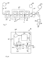
- Fig. 1 and Fig. 2 illustrate the basic sequence of a method for producing a security document, in particular a ticket or a ticket.
- Fig. 1 illustrates the production of security documents in an advantageous large-scale roll-to-roll process
- Fig. 2 the individualization of the thus produced Security documents at the point of sale, for example in a ticket machine.
- Fig. 1 shows a plurality of film rolls 81, 82, 83 and 84, a plurality of printing units 63, 61 and 62.
- the printing units 61 to 63 are preferably gravure or offset printing devices.
- thermosensitive coating which is veranladbar by the action of heat, in particular by means of a thermal print head, to a color change.
- the thermosensitive coating can be applied to the carrier layer 10 from the printing unit 63 over the whole area or even in pattern form.
- the multi-layer body 1 'thus formed comprising the carrier layer 10 and the applied thermosensitive coating is then fed to a printing device 60, which may comprise one or more printing units 61.
- the printing unit 63 can also be arranged in a separate machine, so that between the printing units 63 and the printing device 60, a winding and re-unwinding of the multi-layer body 1 'takes place.
- the printing units 61 one or more further layers are now printed on the top and / or bottom of the multi-layer body 1 '.
- These layers may, for example, be optical information-indicating layers, protective layers and / or adhesion-promoting layers.
- the carrier substrate 1 thus formed is now fed to the printing unit 62.
- the printing unit 62 prints an adhesive layer on the side of the carrier substrate 1, on which the thermosensitive coating is applied to the carrier layer 10.
- the adhesive layer can be printed on the carrier substrate 1 over the entire surface or in a pattern, as will also be explained in detail below.
- the printed adhesive layer preferably consists of a cold adhesive or a UV-curable adhesive.
- the film web thus formed is then fed to the applicator 70.
- a film web forming a transfer film 20 is wound up.
- the application device 70 preferably has an applicator roller 71 and a counterpressure roller 72, which press the carrier substrate with the adhesive layer comprising the film web and the transfer film 20 against each other.
- the adhesive layer is activated and the region of the transfer layer of the transfer film 20 contacted with the adhesive layer is connected to the carrier substrate 1 via the adhesive layer.
- the transfer film 20 is removed from the carrier substrate 1 by passing the webs apart, with the region of the transfer layer contacted with the adhesive layer detaching from the transfer film 20 and remaining as a film element on the adhesive layer.
- the remainder of the transfer film 20 is wound on the film rolls 83.
- the film web thus formed is then fed to the separating device 73 which separates the film web into individual, in particular strip-shaped, regions of a predetermined length cuts.
- the thus formed security document 30, which here consists of a security paper which can be singulated into a plurality of individual security documents, is then wound on the film roll 84.
- thermosensitive coating substrate As the starting material, the use of thermal paper as a substrate provided with a thermosensitive coating, for example the paper Mitsubishi Thermoscript TF 12 or Mitsubishi Thermoscript TF 7067, has proved to be useful.
- the printing device 60 it is also possible to dispense with the printing device 60 and, for example, directly supply the thermal paper wound on a film roll to the printing group 62. Furthermore, it is also possible that, for example, the thermal paper is printed in a separate production device by means of the printing device 60 and the film roll thus produced is then transported to the printing unit 62 and fed to the printing unit 62 as a starting substrate.
- the printing with the adhesive can also be done by means of a sheet-fed press.
- the application of the transfer film can also be done by means of appropriate plunger.
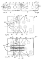
- the transfer film 20 has a carrier film 21 and a transfer layer 27 which can be separated or detached from it.
- a release layer 22 is applied, which preferably consists of a layer containing wax components, which facilitates the detachment of the transfer layer 27 of the carrier film 21.
- the transfer layer 27 preferably has a sequence of a protective lacquer layer 23, one or more decorative layers 24, 25 and an adhesion-promoting layer 26.
- the protective lacquer layer 23 preferably has a layer thickness of approximately 1 ⁇ m.
- the adhesion-promoting layer 26 preferably has a layer thickness of less than 1 ⁇ m.
- the protective lacquer layer 23 and the adhesion-promoting layer 26 as well as also the release layer 22 could also be dispensed with.
- the decorative layer has at least one optical security feature.
- the decorative layer may in this case likewise consist of one or more layers, which are required in order to generate the corresponding security features.
- the decorative layer may have a layer containing a security print, a UV or IR print, a microprint or an imprint or a layer containing optically variable pigments.
- a security print e.g., a security print
- a UV or IR print e.g., a UV or IR print
- a microprint or an imprint e.g., a layer containing optically variable pigments.
- Such layers are generated, for example, by printing corresponding printing materials by means of suitable printing processes, it also being possible to use printing processes such as intaglio printing, intaglio printing or pad printing.
- Security layers are thus provided by such layers, which are characterized by a security print, a microfilm recognizable by means of a microscope, a UV or IR print detectable by UV or IR illumination, or a color shift effect generated by the optically variable pigments.
- the decorative layer comprises layers which provide a refractive element, a diffractive element, an anisotropic matt structure, a relief hologram or a zero-order diffraction structure which provide one or more optically detectable, in particular optically variable security features.
- the decorative layer preferably comprises a replication layer and a reflection-enhancing layer, wherein one or more relief structures are molded into a surface of the replication layer, in particular into the interface between replication layer and reflection-enhancing layer.
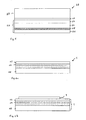
- the embodiment according to Fig. 3 and Fig. 5 illustrates a transfer layer 27 with such a decorative layer, which has a replication layer 24 and a preferably adjacent to this reflection-enhancing layer 25.
- the replication layer 24 preferably consists of a thermoplastic or UV-curable replication lacquer layer of a layer thickness between 1 and 3 ⁇ m.
- the relief structure is molded by means of a corresponding replication tool using heat and pressure, using a thermoplastic replication layer, or by subsequent or simultaneous UV irradiation with a UV-curable replication layer.
- the relief structures may be the relief structure of a 2D / 3D hologram, which is holographically generated and copied onto the replication master.
- the relief structures can also be computer-generated holograms and diffractive elements, for example a Kinegram®.
- Such relief structures preferably have a spatial frequency between 100 lines / mm and 5000 lines / mm and optionally have a plurality of different areas, which are covered with relief structures that differ in their Spatialfrequenz, their azimuth angle and / or relief shape and so generate a desired optically variable appearance.
- the relief structures may also be relief structures which form matt structures, in particular anisotropic matt structures.
- Anisotropic matt structures are here understood to mean matt structures whose scattering characteristic is dependent on the viewing angle and thus an optically variable appearance shows. These matt structures are preferably generated holographically, but can also be formed by a corresponding computer-generated arrangements of diffractive elements. Furthermore, it is possible for the relief structures to form refractive elements, for example to form lenses, microlens screens or microprisms. Furthermore, it is also possible for the relief structures to form a zero-order diffraction structure. These diffraction structures are formed by gratings, in particular regular gratings, for example cross gratings or linear gratings, in which the spacing of the individual structural elements from each other is less than a wavelength ⁇ in the visible light range. By such relief structures, a striking optically variable security feature is provided in which the viewer shows a color change when turning.
- the reflection-enhancing layer 25 may be formed over the entire surface or partially. Furthermore, it is also possible for the reflection-intensifying layer 25 to be formed in regions as an opaque reflection-enhancing layer and as a transparent reflection-enhancing layer in some regions.
- the transparent reflection-enhancing layer it is preferable to use a (transparent) layer whose refractive index differs from the refractive index of the replication layer 24 by at least 0.2.
- an HRI or LRI layer for example ZnS, is used as the transparent reflection-enhancing layer.
- a metal layer which is selected to be correspondingly thin, that the layer still has at least some residual transmissivity for the human eye, or which is correspondingly finely structured, so that this layer still provides sufficient light is transmitted and in particular arranged below this layer information is still visible to the human observer.
- Opaque reflection-enhancing layers are preferably formed by a metal layer or by a transparent reflection-enhancing layer provided with a corresponding opaque lacquer layer.
- the metals used for the reflection-enhancing layer 25 are preferably aluminum, silver, gold and copper. In this case, it is also possible for different regions of the reflection-enhancing layer 25 to be formed from different metals, which due to their inherent color also cause a corresponding different visual appearance of the corresponding optical security features.
- a volume hologram layer in which a volume hologram is inscribed, to be used as the decorative layer.
- the decorative layer may have one or more thin film layer elements which generate a viewing angle-dependent color shift effect.
- a thin-film layer element has one or more spacer layers adjoining a medium with different refractive index, the optical thickness of which is in the range of ⁇ / 2 or ⁇ / 4 for a wavelength ⁇ in the range of visible light.
- Such a thin-film layer element may thus consist, for example, of a sequence of an absorption layer, for example a thin metal layer, a dielectric spacer layer and a reflection-enhancing layer, or else an even or odd sequence consist of high and low refractive layers, which act as spacer layers.
- the decorative layer has a crosslinked liquid-crystal layer.
- Such liquid crystal layers on the one hand show recognizable security features by means of a polarizer.
- a cholesteric liquid crystal material By using a cholesteric liquid crystal material, it is further possible to provide such a liquid crystal layer with a security feature exhibiting a viewing angle-dependent color shifting effect.
- Fig. 3 shows a plan view of a section of the transfer layer 27 of the transfer sheet 20. As in Fig. 3 indicated this section is intended to provide two film elements 2 for the application to security documents.
- the respective film element 2 providing sections are constructed identically.
- the film elements 2 thus each have a region 41 in which the film element is formed transparent, and a region 42 in which the film element 2 is not formed transparent.
- One or more security features 51 are provided in the transparent area 41 and one or more security features 52 are provided in the non-transparent area 42.
- the security features 51 and 52 are provided by the corresponding configuration of the decorative layer as described above.
- the security features 51 thus represent security features which can be recognized in incident light and which are arranged in a transparent region of the film element 2, and the security features 52 represent security features which can be seen in incident light and which are arranged in an opaque region of the film element 2.
- an optically recognizable security feature can further be implemented in the film element 2.
- the security features 51 and 52 may each be formed by diffractive relief structures and / or matt structures, which are coated in the non-transparent region 42 with an opaque metallic reflection layer, in particular of vapor-deposited aluminum, and coated in the transparent region 41 with a transparent vapor-deposited HRI reflection layer are.
- Fig. 6a shows a sectional view of the printing unit 62 supplied to the carrier substrate 1.
- the carrier substrate 1 comprises the carrier layer 10 and the above-mentioned thermosensitive coating 11 and a layer 12 applied by the printing device 60 on.
- the thermosensitive coating applied to the carrier layer 10 extends at least in regions into the volume of the carrier layer 10.
- the carrier layer 10 is preferably a paper layer, preferably with a layer thickness between 70 ⁇ m and 250 ⁇ m, for example 125 ⁇ m.
- the carrier layer further preferably has a weight per unit area of 40 to 300 g / m 2 (oven-dry).
- the carrier layer it is also possible for the carrier layer to consist of one or more paper and / or plastic layers and in particular of a sequence of paper and plastic layers.
- the thermosensitive coating 10 may consist of one or more layers.
- the thermosensitive coating may comprise, for example, a first coating which has thermal energy-insulating properties (insulation layer), a thermoreactive layer applied thereto and a protective layer applied thereto.
- the insulating layer preferably contains pigments selected from the group consisting of kaolin, calcined kaolin, calcium carbonate, zinc oxide, aluminum oxide, titanium dioxide, silicon dioxide, aluminum hydroxide, barium sulfate, zinc sulfate, talc, clay, colloidal silica, hollow sphere pigments or mixtures thereof.
- the thermosensitive coating preferably comprises a thermal reactive layer containing, for example, leuco dyes which are colorless in the unexcited state, and co-reactants which react with each other when heat is applied in a melt.
- leuco dyes a lactone ring is thermally opened and a color reaction occurs.
- the thermal reactive layer preferably contains a paint base and / or a color developing material. Examples of such colorants are triarylmetane-based colorants, diphenylmethane-based colorants, spiro-based colorants and fluoran-based colorants.
- the color developing material may be selected from organic or inorganic materials which initiate the color reaction in contact with the color base materials.
- the color developing material is preferably acidic.
- inorganic color developing materials are activated clay, attapulgites, colloidal silica, aluminum silicate and the like.
- organic color developing materials are phenolic compounds, salts of phenolic compounds or aromatic carboxylic acids and the like with polyvalent metals such as zinc, magnesium, aluminum, calcium, titanium, manganese, tin, nickel and the like and / or pyridine complexes of zinc thiocyanates.
- thermosensitive coating or the individual layers which make up the thermosensitive coating preferably each have an application weight of from 1 to 20 g / mm (oven-dried) after drying.
- the layer 12 preferably forms a layer providing an optical information.
- This layer consists in particular of a security printing, a colored lacquer layer, a layer containing optically variable pigments, UV or IR-active pigments or dyes.
- This layer thus preferably provides a basic information which is uniform for all value documents, for example all tickets.
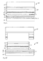
- the adhesive layer 3 is preferably applied in a pattern in a shape which is to correspond to the shape of the film element 2 on the carrier substrate.
- the transfer film 20 is then brought together with the carrier substrate 1, so that the adhesive layer 3 between the transfer film 20 and the carrier substrate 1 is arranged.
- the transfer film 20 adheres to the carrier substrate 1 in these areas, so that after removal of the transfer film 20 from the carrier substrate 1 the area of the transfer layer 27 contacted by the adhesive layer 3 is detached from the transfer film 20 and as the film element 2 remains on the carrier substrate 1.
- the resulting security document 30 is exemplified in plan view in FIG Fig. 4a shown.
- Fig. 4a shows the security document 30 with the carrier substrate 1 and the film element 2.
- the layer 12 of the carrier substrate 1 represents a plurality of optical Information 53 ready, which in Fig. 4a exemplified by dashed lines.
- the film element 2 shows in the embodiment Fig. 4a
- the film element 2 has any other shape, for example, the security document 30 is covered over the entire surface or, for example, shaped in the form of a patch.
- the shape of the film element 2 is, as already described above, determined by the shape of the adhesive layer 3, so that the film element 2 may have any arbitrary shape. So it is for example advantageous that the edges in a strip-shaped design of the film element 2 is not straight as in Fig. 4a are indicated, but for example jagged or in the form of a pattern and thus form an additional security feature.
- the film element 2 has one or more transparent regions 41, in which the underlying regions of the carrier substrate 1 can be seen by the human observer under at least one spatial direction.
- the information 53 applied to the carrier substrate 1 is as shown in FIG Fig. 4a indicated, visible through the film element 2 through.
- one or more security features 51 are generated by the decorative layer or the decorative layers of the film element 2 in the region 41 of the film element 2, so that one or more of the optical security features of the decorative layer are arranged in one of the transparent regions 41.
- the security features 51 are preferably security features that only reflect part of the incident light to generate an optical security feature by diffraction / reflection and transmit part of the light, so that the underlying information 53 can be seen through these security features 51 and overlay with these optically.
- security features are generated, for example, by the layer structure described above with a replication layer and a transparent reflection-enhancing layer.
- the film element 2 preferably also has one or more opaque areas 42, in which the underlying information of the carrier substrate is not or only with difficulty recognizable to the human observer.
- the security features 52 are further provided. In the above exemplary embodiment, these are formed, for example, by a replication layer with shaped relief structures and an opaque reflection-enhancing layer.
- Fig. 2 shows the schematic structure of a device 9 for outputting an individualized security document.
- the device 9 represents, for example, a ticket vending machine.
- the device 9 has an input device 94, a control device 93, a printer 91 and an output device 92.
- the device 9 is a according to Fig. 1 produced film roll 84 supplied.
- the security document formed as security paper 30 is unwound from the film roll 84 and fed to the printer 91.
- the printer 91 has at least one thermal print head 911, which is provided by the control device 93 is controlled.
- the thermal printhead 911 is brought into contact with the top of the security document 30 as shown in FIG Fig. 7a is indicated. Heating elements 912 of the thermal printing head 911 are thus brought into contact with the side of the security paper 30 on which the film element 2 is applied to the carrier substrate 1.
- Fig. 1 produced film roll 84 supplied.
- the security document formed as security paper 30 is unwound from the film roll 84 and fed to the printer 91.
- the printer 91 has at least one thermal print head 911, which is provided by the control device 93 is controlled.
- the thermal printhead 911 is brought into contact with
- thermosensitive coating 11 is partially activated and excited to a color change.
- printer 91 CAB a4 + (cab Mathtechnik GmbH & Co. KG, Düsseldorf), Avery Dennison 64-08 (Avery Dennison, USA), Zebra 110Xi4 (Zebra Technologies Corporation USA).
- the individualized security document 30 ' is optionally separated from the film web and separated, and then output as an individualized security document 30 ".
- the security document 30 is exemplary in FIG Fig. 4b shown.
- the security document 30 "is like the security document 30 after Fig. 4a constructed, except that in addition by area-wise activation of the color change of the thermo-sensitive coating 11 information 54 is inscribed in the security document.
- the security document 30 thus has the carrier substrate 1 with the information 53 and the film element 2 with the transparent areas 41, the opaque areas 42 and the security features 51 and 52.
- the information 54 is written into the security document such that at least part of the information 54 is covered by a transparent region 41 of the film element 2. Thus at least part of the information 54 is visible through the film element 2.
Landscapes
- Physics & Mathematics (AREA)
- Optics & Photonics (AREA)
- General Physics & Mathematics (AREA)
- Engineering & Computer Science (AREA)
- Theoretical Computer Science (AREA)
- Chemical & Material Sciences (AREA)
- Chemical Kinetics & Catalysis (AREA)
- General Chemical & Material Sciences (AREA)
- Credit Cards Or The Like (AREA)
- Heat Sensitive Colour Forming Recording (AREA)
Priority Applications (1)
| Application Number | Priority Date | Filing Date | Title |
|---|---|---|---|
| PL13701240T PL2807036T3 (pl) | 2012-01-23 | 2013-01-21 | Dokument bezpieczny jak i sposób wytwarzania dokumentu bezpiecznego |
Applications Claiming Priority (2)
| Application Number | Priority Date | Filing Date | Title |
|---|---|---|---|
| DE102012001121.0A DE102012001121C5 (de) | 2012-01-23 | 2012-01-23 | Sicherheitsdokument, Verfahren zur Herstellung eines Sicherheitsdokuments und Verfahren zur Herstellung eines individualisierten Sicherheitsdokuments |
| PCT/EP2013/051024 WO2013110565A1 (de) | 2012-01-23 | 2013-01-21 | Sicherheitsdokument sowie verfahren zur herstellung eines sicherheitsdokuments |
Publications (2)
| Publication Number | Publication Date |
|---|---|
| EP2807036A1 EP2807036A1 (de) | 2014-12-03 |
| EP2807036B1 true EP2807036B1 (de) | 2015-12-23 |
Family
ID=47603688
Family Applications (1)
| Application Number | Title | Priority Date | Filing Date |
|---|---|---|---|
| EP13701240.7A Active EP2807036B1 (de) | 2012-01-23 | 2013-01-21 | Sicherheitsdokument sowie verfahren zur herstellung eines sicherheitsdokuments |
Country Status (8)
| Country | Link |
|---|---|
| US (1) | US9321294B2 (pl) |
| EP (1) | EP2807036B1 (pl) |
| CN (1) | CN104169098B (pl) |
| DE (1) | DE102012001121C5 (pl) |
| ES (1) | ES2565311T3 (pl) |
| PL (1) | PL2807036T3 (pl) |
| RS (1) | RS54621B1 (pl) |
| WO (1) | WO2013110565A1 (pl) |
Families Citing this family (22)
| Publication number | Priority date | Publication date | Assignee | Title |
|---|---|---|---|---|
| DE102013221337A1 (de) * | 2013-10-21 | 2015-04-23 | Bundesdruckerei Gmbh | Verfahren zum Bilden mindestens einer dreidimensionalen Struktur auf mindestens einer Oberfläche eines Substrats |
| DE102014112073A1 (de) * | 2014-08-22 | 2016-02-25 | Ovd Kinegram Ag | Transferfolie sowie Verfahren zur Herstellung einer Transferfolie |
| DE102014116940A1 (de) | 2014-11-19 | 2016-05-19 | Leonhard Kurz Stiftung & Co. Kg | Mehrschichtkörper und Verfahren zu dessen Herstellung |
| DE102014118366A1 (de) | 2014-12-10 | 2016-06-16 | Ovd Kinegram Ag | Mehrschichtkörper und Verfahren zu dessen Herstellung |
| CA3015522C (en) * | 2015-02-24 | 2019-01-08 | Igt Global Solutions Corporation | Distributed production of lottery tickets |
| DE102015105285A1 (de) * | 2015-04-08 | 2016-10-13 | Kurz Typofol Gmbh | Verfahren zur Herstellung eines Dokuments sowie ein Dokument |
| US9842456B2 (en) * | 2015-07-01 | 2017-12-12 | Xerox Corporation | Vending machine for creating and dispensing personalized articles |
| CN105023505B (zh) * | 2015-07-30 | 2018-06-08 | 李峰 | 一种局部纹理防伪结构及其制造方法、防伪方法 |
| PL3178660T3 (pl) | 2015-12-07 | 2019-07-31 | Hueck Folien Ges.M.B.H | Personalizowany element zabezpieczający |
| DE102016109633B4 (de) * | 2016-05-25 | 2022-12-29 | Leonhard Kurz Stiftung & Co. Kg | Verfahren zur Herstellung einer Volumenhologrammfolie mit als Übertragungsabschnitte ausgebildeten Sicherheitselementen |
| CN106313934B (zh) * | 2016-09-29 | 2017-04-26 | 滕泽其 | 用于防伪的安全元件及其制造方法和安全票证 |
| US11065910B2 (en) * | 2017-07-14 | 2021-07-20 | Illinois Tool Works Inc. | Color shifting heat transfer label |
| JP6986885B2 (ja) * | 2017-07-20 | 2021-12-22 | 共同印刷株式会社 | 証券 |
| US11351710B2 (en) | 2018-11-05 | 2022-06-07 | Case Western Reserve University | Multilayered structures and uses thereof in security markings |
| US11194094B2 (en) | 2018-11-05 | 2021-12-07 | Case Western Reserve University | Multilayered structures and uses thereof in security markings |
| DE102019001422A1 (de) * | 2019-02-28 | 2020-09-03 | Giesecke+Devrient Currency Technology Gmbh | Transfervorrichtung und Verfahren in einer Transfervorrichtung |
| US20200338922A1 (en) * | 2019-04-26 | 2020-10-29 | Viavi Solutions Inc. | Optical device with magnetic flakes and structured substrate |
| DE102019005551A1 (de) * | 2019-08-07 | 2021-02-11 | Giesecke+Devrient Currency Technology Gmbh | Herstellverfahren für ein Sicherheitspapier und damit erhältliches Sicherheitspapier |
| CN110481199A (zh) * | 2019-09-06 | 2019-11-22 | 中国民航大学 | 一种飞机登机牌技术 |
| CN111823746B (zh) * | 2020-05-26 | 2021-10-29 | 湖南天琪智慧印刷有限公司 | 用于防伪票据的防伪热敏纸及其制作方法 |
| CN115230277A (zh) * | 2021-04-25 | 2022-10-25 | 中钞特种防伪科技有限公司 | 薄膜元件、透明防伪元件、及数据载体 |
| CN114179541A (zh) * | 2021-12-15 | 2022-03-15 | 公安部交通管理科学研究所 | 一种证卡签注方法 |
Family Cites Families (27)
| Publication number | Priority date | Publication date | Assignee | Title |
|---|---|---|---|---|
| DE2907004C2 (de) * | 1979-02-22 | 1981-06-25 | GAO Gesellschaft für Automation und Organisation mbH, 8000 München | Ausweiskarte und Verfahren zu ihrer Herstellung |
| DE3151407C1 (de) * | 1981-12-24 | 1983-10-13 | GAO Gesellschaft für Automation und Organisation mbH, 8000 München | Ausweiskarte und Verfahren zu deren Herstellung |
| ATE59717T1 (de) | 1985-10-01 | 1991-01-15 | Maurer Electronics Gmbh | Kartenfoermiger datentraeger und verfahren zu seiner herstellung. |
| ES2038119T3 (es) | 1985-10-15 | 1993-07-16 | Gao Gesellschaft Fur Automation Und Organisation Mbh | Soporte de datos con caracteristica optica de autenticidad, asi como procedimiento para la fabricacion y comprobacion de dicho soporte de datos. |
| ATE124153T1 (de) | 1989-06-05 | 1995-07-15 | Landis & Gyr Betriebs Ag | Schichtverbund mit beugungstrukturen. |
| EP0537439B2 (de) * | 1991-10-14 | 2003-07-09 | OVD Kinegram AG | Sicherheitselement |
| EP0556071B1 (en) | 1992-02-13 | 1997-09-17 | Fujitsu Limited | Ticket printer |
| CN2166496Y (zh) * | 1993-08-12 | 1994-05-25 | 李晓茹 | 防伪标识 |
| DE4339216A1 (de) | 1993-11-18 | 1994-04-21 | Raoul Dr Nakhmanson | Termosensitiver Aufzeichnungsträger für farbige Darstellungen |
| DE69515928T2 (de) * | 1994-05-30 | 2000-10-05 | Agfa Gevaert Nv | Wärmeempfindliches Aufzeichnungsmaterial |
| DE69500570T2 (de) * | 1994-06-15 | 1998-02-26 | Agfa Gevaert Nv | Wärmeempfindliches Aufzeichnungsverfahren |
| DE19915943A1 (de) | 1999-04-09 | 2000-10-12 | Ovd Kinegram Ag Zug | Dekorationsfolie |
| ES2269067T3 (es) * | 1999-04-22 | 2007-04-01 | Ricoh Company, Ltd. | Activar y grabar mediante calor una etiqueta adhesiva termosensible. |
| DE10008851A1 (de) * | 2000-02-25 | 2001-08-30 | Giesecke & Devrient Gmbh | Verfahren zur Herstellung laserbeschriftbarer Datenträger und damit hergestellte Datenträger |
| JP4137498B2 (ja) * | 2002-04-22 | 2008-08-20 | セイコーインスツル株式会社 | 熱活性シートの熱活性化装置およびその熱活性化装置を用いたプリンタ装置 |
| JP2005529004A (ja) * | 2002-05-08 | 2005-09-29 | レオナード クルツ ゲーエムベーハー ウント コンパニー カーゲー | 少なくとも一部分に紙材料を含む基材を備えた多層体およびそのような多層体にレーザ誘起マークを作成する方法 |
| DE10243653A1 (de) | 2002-09-19 | 2004-04-01 | Giesecke & Devrient Gmbh | Sicherheitspapier |
| DE102005017170B4 (de) * | 2005-04-13 | 2010-07-01 | Ovd Kinegram Ag | Transferfolie, Verfahren zu deren Herstellung sowie Mehrschichtkörper und dessen Verwendung |
| DE102005017169B4 (de) * | 2005-04-13 | 2023-06-22 | Ovd Kinegram Ag | Transferfolie |
| DE102006022798A1 (de) * | 2006-05-08 | 2007-11-15 | Puttkammer, Frank | Manipulationsgeschütztes geldwertes Blattgut |
| DE102007044482A1 (de) | 2007-09-18 | 2009-03-19 | Giesecke & Devrient Gmbh | Sicherheitselement mit Tamper Evident-Effekt |
| DE102008005136A1 (de) | 2008-01-16 | 2009-07-23 | U-Nica Technology Ag | Dokument sowie Verfahren zur Herstellung eines Dokumentes |
| DE102008005019B4 (de) * | 2008-01-17 | 2010-08-05 | Ovd Kinegram Ag | Folienelement sowie die Verwendung dieses Folienelements |
| DE102008019092A1 (de) * | 2008-04-16 | 2009-10-22 | Giesecke & Devrient Gmbh | Verfahren zur Herstellung eines Sicherheits- oder Wertdokuments |
| DE102008062149B3 (de) | 2008-12-16 | 2010-04-29 | Ovd Kinegram Ag | Verfahren zur Herstellung eines Sicherheitselements sowie Transferfolie |
| EP2199100A1 (en) * | 2008-12-22 | 2010-06-23 | Agfa-Gevaert N.V. | Security laminates for security documents. |
| KR101608764B1 (ko) | 2009-07-14 | 2016-04-04 | 엘지전자 주식회사 | 이동 단말기 및 이것의 디스플레이 제어 방법 |
-
2012
- 2012-01-23 DE DE102012001121.0A patent/DE102012001121C5/de active Active
-
2013
- 2013-01-21 RS RS20160103A patent/RS54621B1/en unknown
- 2013-01-21 US US14/374,057 patent/US9321294B2/en active Active
- 2013-01-21 PL PL13701240T patent/PL2807036T3/pl unknown
- 2013-01-21 ES ES13701240.7T patent/ES2565311T3/es active Active
- 2013-01-21 CN CN201380014175.1A patent/CN104169098B/zh active Active
- 2013-01-21 EP EP13701240.7A patent/EP2807036B1/de active Active
- 2013-01-21 WO PCT/EP2013/051024 patent/WO2013110565A1/de active Application Filing
Also Published As
| Publication number | Publication date |
|---|---|
| CN104169098A (zh) | 2014-11-26 |
| WO2013110565A1 (de) | 2013-08-01 |
| ES2565311T3 (es) | 2016-04-01 |
| DE102012001121A1 (de) | 2013-07-25 |
| RS54621B1 (en) | 2016-08-31 |
| CN104169098B (zh) | 2016-08-24 |
| EP2807036A1 (de) | 2014-12-03 |
| US20150018206A1 (en) | 2015-01-15 |
| US9321294B2 (en) | 2016-04-26 |
| DE102012001121B4 (de) | 2014-02-20 |
| PL2807036T3 (pl) | 2016-06-30 |
| DE102012001121C5 (de) | 2018-01-04 |
Similar Documents
| Publication | Publication Date | Title |
|---|---|---|
| EP2807036B1 (de) | Sicherheitsdokument sowie verfahren zur herstellung eines sicherheitsdokuments | |
| EP0537439B2 (de) | Sicherheitselement | |
| EP1330369B1 (de) | Mehrschichtenkörper, insbesondere mehrschichtenfolie sowie verfahren zur erhöhung der fälschungssicherheit eines mehrschichtenkörpers | |
| EP2303594B1 (de) | Sicherheitselement | |
| EP2265999B1 (de) | Holographisches sicherheitselement sowie verfahren zu seiner herstellung | |
| EP3183124B1 (de) | Transferfolie sowie verfahren zur herstellung einer transferfolie | |
| EP2585314B1 (de) | Verfahren zur dekoration von oberflächen | |
| EP1132862A2 (de) | Datenträger mit einem optisch variablen Element | |
| WO2016162439A1 (de) | Verfahren zur herstellung eines dokuments sowie ein dokument | |
| EP3802144B1 (de) | Verfahren zur herstellung eines laminatkörpers und einer laminierfolie sowie laminatkörper und laminierfolie | |
| DE102007005416B4 (de) | Prägefolie und damit gebildeter Sicherheitsaufkleber | |
| EP1664863B1 (de) | Verfahren und foliensystem zur herstellung eines individualisierten optisch variablen elements | |
| EP3894232B1 (de) | Verfahren zur herstellung eines folienzwischenprodukts, folienzwischenprodukt sowie verfahren zur herstellung eines produkts | |
| OA20537A (en) | Method for creating security element on security documents, security document containing security element, and hot stamping foil for security document. | |
| EP3060409B1 (de) | Mit mindestens einem druckmerkmal versehenes druckprodukt, verfahren zu dessen herstellung und transferfolie | |
| EP3060408B1 (de) | Verfahren zum bilden mindestens einer dreidimensionalen struktur auf mindestens einer oberfläche eines substrats und transferfolie | |
| EP3860863A2 (en) | Method for creating security element on security documents, security document containing security element, and hot stamping foil for security document | |
| EP3041685B1 (de) | Sicherheitsdokument mit zumindest einem eine strukturierung umfassenden sicherheitselement und verfahren zu dessen herstellung |
Legal Events
| Date | Code | Title | Description |
|---|---|---|---|
| PUAI | Public reference made under article 153(3) epc to a published international application that has entered the european phase |
Free format text: ORIGINAL CODE: 0009012 |
|
| 17P | Request for examination filed |
Effective date: 20140814 |
|
| AK | Designated contracting states |
Kind code of ref document: A1 Designated state(s): AL AT BE BG CH CY CZ DE DK EE ES FI FR GB GR HR HU IE IS IT LI LT LU LV MC MK MT NL NO PL PT RO RS SE SI SK SM TR |
|
| DAX | Request for extension of the european patent (deleted) | ||
| REG | Reference to a national code |
Ref country code: DE Ref legal event code: R079 Ref document number: 502013001653 Country of ref document: DE Free format text: PREVIOUS MAIN CLASS: B41M0005260000 Ipc: B42D0025000000 |
|
| GRAP | Despatch of communication of intention to grant a patent |
Free format text: ORIGINAL CODE: EPIDOSNIGR1 |
|
| RIC1 | Information provided on ipc code assigned before grant |
Ipc: B42D 25/00 20140101AFI20150609BHEP |
|
| INTG | Intention to grant announced |
Effective date: 20150630 |
|
| GRAS | Grant fee paid |
Free format text: ORIGINAL CODE: EPIDOSNIGR3 |
|
| GRAA | (expected) grant |
Free format text: ORIGINAL CODE: 0009210 |
|
| AK | Designated contracting states |
Kind code of ref document: B1 Designated state(s): AL AT BE BG CH CY CZ DE DK EE ES FI FR GB GR HR HU IE IS IT LI LT LU LV MC MK MT NL NO PL PT RO RS SE SI SK SM TR |
|
| REG | Reference to a national code |
Ref country code: GB Ref legal event code: FG4D Free format text: NOT ENGLISH |
|
| REG | Reference to a national code |
Ref country code: CH Ref legal event code: EP Ref country code: CH Ref legal event code: NV Representative=s name: FIAMMENGHI-FIAMMENGHI, CH |
|
| REG | Reference to a national code |
Ref country code: FR Ref legal event code: PLFP Year of fee payment: 4 |
|
| REG | Reference to a national code |
Ref country code: IE Ref legal event code: FG4D Free format text: LANGUAGE OF EP DOCUMENT: GERMAN |
|
| REG | Reference to a national code |
Ref country code: AT Ref legal event code: REF Ref document number: 766377 Country of ref document: AT Kind code of ref document: T Effective date: 20160115 |
|
| REG | Reference to a national code |
Ref country code: DE Ref legal event code: R096 Ref document number: 502013001653 Country of ref document: DE |
|
| REG | Reference to a national code |
Ref country code: NL Ref legal event code: FP |
|
| REG | Reference to a national code |
Ref country code: ES Ref legal event code: FG2A Ref document number: 2565311 Country of ref document: ES Kind code of ref document: T3 Effective date: 20160401 |
|
| PG25 | Lapsed in a contracting state [announced via postgrant information from national office to epo] |
Ref country code: HR Free format text: LAPSE BECAUSE OF FAILURE TO SUBMIT A TRANSLATION OF THE DESCRIPTION OR TO PAY THE FEE WITHIN THE PRESCRIBED TIME-LIMIT Effective date: 20151223 Ref country code: NO Free format text: LAPSE BECAUSE OF FAILURE TO SUBMIT A TRANSLATION OF THE DESCRIPTION OR TO PAY THE FEE WITHIN THE PRESCRIBED TIME-LIMIT Effective date: 20160323 |
|
| PG25 | Lapsed in a contracting state [announced via postgrant information from national office to epo] |
Ref country code: BE Free format text: LAPSE BECAUSE OF NON-PAYMENT OF DUE FEES Effective date: 20160131 Ref country code: SE Free format text: LAPSE BECAUSE OF FAILURE TO SUBMIT A TRANSLATION OF THE DESCRIPTION OR TO PAY THE FEE WITHIN THE PRESCRIBED TIME-LIMIT Effective date: 20151223 Ref country code: GR Free format text: LAPSE BECAUSE OF FAILURE TO SUBMIT A TRANSLATION OF THE DESCRIPTION OR TO PAY THE FEE WITHIN THE PRESCRIBED TIME-LIMIT Effective date: 20160324 Ref country code: LV Free format text: LAPSE BECAUSE OF FAILURE TO SUBMIT A TRANSLATION OF THE DESCRIPTION OR TO PAY THE FEE WITHIN THE PRESCRIBED TIME-LIMIT Effective date: 20151223 |
|
| PG25 | Lapsed in a contracting state [announced via postgrant information from national office to epo] |
Ref country code: CZ Free format text: LAPSE BECAUSE OF FAILURE TO SUBMIT A TRANSLATION OF THE DESCRIPTION OR TO PAY THE FEE WITHIN THE PRESCRIBED TIME-LIMIT Effective date: 20151223 |
|
| PG25 | Lapsed in a contracting state [announced via postgrant information from national office to epo] |
Ref country code: PT Free format text: LAPSE BECAUSE OF FAILURE TO SUBMIT A TRANSLATION OF THE DESCRIPTION OR TO PAY THE FEE WITHIN THE PRESCRIBED TIME-LIMIT Effective date: 20160426 Ref country code: LU Free format text: LAPSE BECAUSE OF FAILURE TO SUBMIT A TRANSLATION OF THE DESCRIPTION OR TO PAY THE FEE WITHIN THE PRESCRIBED TIME-LIMIT Effective date: 20160121 Ref country code: RO Free format text: LAPSE BECAUSE OF FAILURE TO SUBMIT A TRANSLATION OF THE DESCRIPTION OR TO PAY THE FEE WITHIN THE PRESCRIBED TIME-LIMIT Effective date: 20151223 Ref country code: SM Free format text: LAPSE BECAUSE OF FAILURE TO SUBMIT A TRANSLATION OF THE DESCRIPTION OR TO PAY THE FEE WITHIN THE PRESCRIBED TIME-LIMIT Effective date: 20151223 Ref country code: EE Free format text: LAPSE BECAUSE OF FAILURE TO SUBMIT A TRANSLATION OF THE DESCRIPTION OR TO PAY THE FEE WITHIN THE PRESCRIBED TIME-LIMIT Effective date: 20151223 Ref country code: SK Free format text: LAPSE BECAUSE OF FAILURE TO SUBMIT A TRANSLATION OF THE DESCRIPTION OR TO PAY THE FEE WITHIN THE PRESCRIBED TIME-LIMIT Effective date: 20151223 Ref country code: IS Free format text: LAPSE BECAUSE OF FAILURE TO SUBMIT A TRANSLATION OF THE DESCRIPTION OR TO PAY THE FEE WITHIN THE PRESCRIBED TIME-LIMIT Effective date: 20160423 |
|
| REG | Reference to a national code |
Ref country code: DE Ref legal event code: R097 Ref document number: 502013001653 Country of ref document: DE |
|
| PG25 | Lapsed in a contracting state [announced via postgrant information from national office to epo] |
Ref country code: MC Free format text: LAPSE BECAUSE OF FAILURE TO SUBMIT A TRANSLATION OF THE DESCRIPTION OR TO PAY THE FEE WITHIN THE PRESCRIBED TIME-LIMIT Effective date: 20151223 |
|
| PLBE | No opposition filed within time limit |
Free format text: ORIGINAL CODE: 0009261 |
|
| STAA | Information on the status of an ep patent application or granted ep patent |
Free format text: STATUS: NO OPPOSITION FILED WITHIN TIME LIMIT |
|
| PG25 | Lapsed in a contracting state [announced via postgrant information from national office to epo] |
Ref country code: DK Free format text: LAPSE BECAUSE OF FAILURE TO SUBMIT A TRANSLATION OF THE DESCRIPTION OR TO PAY THE FEE WITHIN THE PRESCRIBED TIME-LIMIT Effective date: 20151223 |
|
| REG | Reference to a national code |
Ref country code: IE Ref legal event code: MM4A |
|
| 26N | No opposition filed |
Effective date: 20160926 |
|
| REG | Reference to a national code |
Ref country code: FR Ref legal event code: PLFP Year of fee payment: 5 |
|
| PG25 | Lapsed in a contracting state [announced via postgrant information from national office to epo] |
Ref country code: IE Free format text: LAPSE BECAUSE OF NON-PAYMENT OF DUE FEES Effective date: 20160121 |
|
| PG25 | Lapsed in a contracting state [announced via postgrant information from national office to epo] |
Ref country code: SI Free format text: LAPSE BECAUSE OF FAILURE TO SUBMIT A TRANSLATION OF THE DESCRIPTION OR TO PAY THE FEE WITHIN THE PRESCRIBED TIME-LIMIT Effective date: 20151223 |
|
| PG25 | Lapsed in a contracting state [announced via postgrant information from national office to epo] |
Ref country code: MT Free format text: LAPSE BECAUSE OF FAILURE TO SUBMIT A TRANSLATION OF THE DESCRIPTION OR TO PAY THE FEE WITHIN THE PRESCRIBED TIME-LIMIT Effective date: 20151223 |
|
| REG | Reference to a national code |
Ref country code: FR Ref legal event code: PLFP Year of fee payment: 6 |
|
| PG25 | Lapsed in a contracting state [announced via postgrant information from national office to epo] |
Ref country code: HU Free format text: LAPSE BECAUSE OF FAILURE TO SUBMIT A TRANSLATION OF THE DESCRIPTION OR TO PAY THE FEE WITHIN THE PRESCRIBED TIME-LIMIT; INVALID AB INITIO Effective date: 20130121 |
|
| PG25 | Lapsed in a contracting state [announced via postgrant information from national office to epo] |
Ref country code: CY Free format text: LAPSE BECAUSE OF FAILURE TO SUBMIT A TRANSLATION OF THE DESCRIPTION OR TO PAY THE FEE WITHIN THE PRESCRIBED TIME-LIMIT Effective date: 20151223 Ref country code: MK Free format text: LAPSE BECAUSE OF FAILURE TO SUBMIT A TRANSLATION OF THE DESCRIPTION OR TO PAY THE FEE WITHIN THE PRESCRIBED TIME-LIMIT Effective date: 20151223 |
|
| PG25 | Lapsed in a contracting state [announced via postgrant information from national office to epo] |
Ref country code: AL Free format text: LAPSE BECAUSE OF FAILURE TO SUBMIT A TRANSLATION OF THE DESCRIPTION OR TO PAY THE FEE WITHIN THE PRESCRIBED TIME-LIMIT Effective date: 20151223 |
|
| PGFP | Annual fee paid to national office [announced via postgrant information from national office to epo] |
Ref country code: FR Payment date: 20230123 Year of fee payment: 11 |
|
| PGFP | Annual fee paid to national office [announced via postgrant information from national office to epo] |
Ref country code: TR Payment date: 20230118 Year of fee payment: 11 Ref country code: RS Payment date: 20230113 Year of fee payment: 11 Ref country code: IT Payment date: 20230131 Year of fee payment: 11 |
|
| PGFP | Annual fee paid to national office [announced via postgrant information from national office to epo] |
Ref country code: PL Payment date: 20231124 Year of fee payment: 12 Ref country code: NL Payment date: 20240123 Year of fee payment: 12 |
|
| PGFP | Annual fee paid to national office [announced via postgrant information from national office to epo] |
Ref country code: LT Payment date: 20240104 Year of fee payment: 12 |
|
| PGFP | Annual fee paid to national office [announced via postgrant information from national office to epo] |
Ref country code: ES Payment date: 20240216 Year of fee payment: 12 |
|
| PGFP | Annual fee paid to national office [announced via postgrant information from national office to epo] |
Ref country code: AT Payment date: 20240118 Year of fee payment: 12 |
|
| PGFP | Annual fee paid to national office [announced via postgrant information from national office to epo] |
Ref country code: FI Payment date: 20240119 Year of fee payment: 12 Ref country code: DE Payment date: 20231124 Year of fee payment: 12 Ref country code: BG Payment date: 20240118 Year of fee payment: 12 Ref country code: GB Payment date: 20240124 Year of fee payment: 12 Ref country code: CH Payment date: 20240202 Year of fee payment: 12 |