EP2807018B1 - Backflow protector - Google Patents
Backflow protector Download PDFInfo
- Publication number
- EP2807018B1 EP2807018B1 EP13700031.1A EP13700031A EP2807018B1 EP 2807018 B1 EP2807018 B1 EP 2807018B1 EP 13700031 A EP13700031 A EP 13700031A EP 2807018 B1 EP2807018 B1 EP 2807018B1
- Authority
- EP
- European Patent Office
- Prior art keywords
- inlet
- container
- line
- assistance system
- inlet valve
- Prior art date
- Legal status (The legal status is an assumption and is not a legal conclusion. Google has not performed a legal analysis and makes no representation as to the accuracy of the status listed.)
- Active
Links
- 230000001012 protector Effects 0.000 title 1
- 239000000565 sealant Substances 0.000 claims description 29
- 230000015556 catabolic process Effects 0.000 claims description 21
- 238000007789 sealing Methods 0.000 claims description 7
- 238000009826 distribution Methods 0.000 description 7
- 239000000463 material Substances 0.000 description 5
- 238000004519 manufacturing process Methods 0.000 description 3
- 230000002950 deficient Effects 0.000 description 2
- 230000000694 effects Effects 0.000 description 2
- 238000003860 storage Methods 0.000 description 2
- 230000015572 biosynthetic process Effects 0.000 description 1
- 238000006243 chemical reaction Methods 0.000 description 1
- 230000001112 coagulating effect Effects 0.000 description 1
- 238000010276 construction Methods 0.000 description 1
- 230000000994 depressogenic effect Effects 0.000 description 1
- 238000005553 drilling Methods 0.000 description 1
- 229920001971 elastomer Polymers 0.000 description 1
- 239000004744 fabric Substances 0.000 description 1
- 210000003746 feather Anatomy 0.000 description 1
- 238000001746 injection moulding Methods 0.000 description 1
- 238000009434 installation Methods 0.000 description 1
- 239000004816 latex Substances 0.000 description 1
- 229920000126 latex Polymers 0.000 description 1
- 238000000034 method Methods 0.000 description 1
- 239000008267 milk Substances 0.000 description 1
- 210000004080 milk Anatomy 0.000 description 1
- 235000013336 milk Nutrition 0.000 description 1
- 238000003801 milling Methods 0.000 description 1
- 239000000203 mixture Substances 0.000 description 1
- 239000004033 plastic Substances 0.000 description 1
- 229920003023 plastic Polymers 0.000 description 1
- 238000003825 pressing Methods 0.000 description 1
- 238000010992 reflux Methods 0.000 description 1
- 239000000243 solution Substances 0.000 description 1
Images

Classifications
-
- B—PERFORMING OPERATIONS; TRANSPORTING
- B29—WORKING OF PLASTICS; WORKING OF SUBSTANCES IN A PLASTIC STATE IN GENERAL
- B29C—SHAPING OR JOINING OF PLASTICS; SHAPING OF MATERIAL IN A PLASTIC STATE, NOT OTHERWISE PROVIDED FOR; AFTER-TREATMENT OF THE SHAPED PRODUCTS, e.g. REPAIRING
- B29C73/00—Repairing of articles made from plastics or substances in a plastic state, e.g. of articles shaped or produced by using techniques covered by this subclass or subclass B29D
- B29C73/16—Auto-repairing or self-sealing arrangements or agents
- B29C73/166—Devices or methods for introducing sealing compositions into articles
-
- B—PERFORMING OPERATIONS; TRANSPORTING
- B29—WORKING OF PLASTICS; WORKING OF SUBSTANCES IN A PLASTIC STATE IN GENERAL
- B29L—INDEXING SCHEME ASSOCIATED WITH SUBCLASS B29C, RELATING TO PARTICULAR ARTICLES
- B29L2030/00—Pneumatic or solid tyres or parts thereof
Definitions
- the invention relates to a breakdown assistance system for sealing and inflating motor vehicle tires, wherein the breakdown assistance system comprises a compressed gas source, preferably a compressor, and a container for a self-sealing means which can be filled into the motor vehicle tire.
- the container has a container opening located at its upper end, and a distributor unit for sealant and compressed gas connected to the container.
- the distributor unit is designed as a lid for the container opening and is provided both with an inlet line which can be connected to the compressed gas source and with an outlet line (4) which can be connected to the motor vehicle tire.
- the intake passage has an intake valve with an intake valve body.
- repair kits which include a compressor, a coagulating in the tire sealant, usually a latex milk mixture, the corresponding connecting hoses and the necessary cable connections for power supply and switch, pressure gauge and control element and thus a constantly deployable and complete
- a repair kit that can be dispensed with the carry on a rim mounted spare wheel or the constant control of other repair materials such as hoses, various tool wrench, jack etc.
- repair kits are not easy. Depending on the operating condition, sealant containers and various hose connections must first be connected or rebuilt. In fact, most repair kits are also well suited to be used without the use of sealant only for inflating tires, inflatable boats, air mattresses, etc. Due to the now rarely occurring punctures the repair kits are usually used more often for such recreational purposes than for emergencies. But when this happens, the user is in an unfamiliar and inexperienced situation.
- a problem with the use in repair cases arises, for example, when the sealant container is falsely connected with its hose or the associated connector first with the tire valve and still prevails a residual pressure in the tire.
- the residual pressure flowing into the container can cause sealant to escape from the container into the environment, provided that safety caps on the Inlet side of the distributor unit are already solved or not present, or that sealant is transported in the direction of already connected to the distribution unit, but not yet switched compressor and there glued valves.
- the object of the invention was to provide a device for sealing and inflating inflatable objects, which provides a secure connection between the sealant container or valve and distributor unit, which allows a simplified application in one or the other mode, the is tolerated easily in faulty connection order in the tire residual pressure and thus safe to handle and in particular has the simplest possible construction with a rugged design and this is easy and inexpensive to manufacture.
- a return flow in the direction of the compressor and there arranged line and valve components is realized in that a valve body, e.g. a slidable O-ring, in the event of pressure build-up in the sealant bottle caused by a pressure source on the outlet side (e.g., residual pressure tires), closes the inlet port / port of the sealant bottle.
- a valve body e.g. a slidable O-ring
- the inlet valve Upon application of compressed gas from the pressure source, i. as soon as the pressure through the pressure source becomes greater than the pressure within the sealant bottle, the inlet valve thus constructed as a "backflow valve" reopens the inlet port / inlet port and the breakdown assistance system can be used as intended.
- the "backflow valve” When used properly, in which the pressurization of the sealant bottle takes place only from the inlet side, the "backflow valve" has virtually no function. As delivered, the inlet channel is not closed by the “reflux valve” in this case. The closure of the bottle is ensured by the cap / screw cap.
- the inlet valve has a closed starting position and the inlet valve when pressurized gas the pressure source opens the inlet line (3) to the container interior.
- Such a design is suitable as an alternative to the basically "open" arrangement of the inlet valve when, for example, for cost reasons, only provide a valve on the inlet side and provide a screw cap designed as simple as possible.
- a further advantageous embodiment consists in that the inlet valve body is permanently displaceable when pressurized gas is applied from the inlet line, in particular in that the inlet line leads into an inlet connection communicating with the container opening, which is designed as an annular space line, wherein the inlet valve body consists of an in the annulus line is inserted O-ring seal.
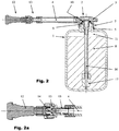
- the Fig. 1 shows a container 1 of a breakdown assistance system according to the invention with the associated distributor unit and the inlet and exhaust valves in section, the breakdown assistance system having a compressed gas source not shown here, which is connected to the distribution unit 2 via an inlet line 3.
- the distributor unit 2 has an outlet line 4, which can be connected to the motor vehicle tire likewise not shown here.
- the distributor unit is designed as a lid or closure for the container opening 5.
- the Fig. 1 also shows a screw cap 6 on the inlet line 3, which must be removed before connecting the container to a compressed gas source.
- the distributor unit 2 is connected via a screw thread 7 with the bottle-shaped sealant container 1.
- the sealant container contains an automatic sealant 8 that can be filled into the inflatable object.
- the outlet line 4 of the container 1 leads to the vehicle tire and consists of a flexible and airtight tube made of rubber.
- a flexible and airtight tube made of rubber.
- plastics and / or fabric materials can be used as a hose material.
- the inlet pipe has an inlet valve with an inlet valve body 10 and is configured so that the inlet pipe 3 in a communicating with the container opening Inlet port leads, which is designed as an annular space line 9, wherein the inlet valve body consists of an inserted into the annulus line 9 O-ring seal 10.
- the formed as an O-ring seal 10 inlet valve body opens when exposed to compressed gas from the pressure source, the inlet line 3 to the container interior 11. In detail, this also shows once again Fig. 1b ,
- the exhaust pipe 4 has at its tire-side end by connection to a tire valve 12, see Fig. 2 and 2a , opening exhaust valve 13 on how it increases in the Fig. 1a and 2a is shown.
- the tire valve 12 is here a so-called Schrader valve.
- the well-known used in motor vehicles Schrader valve is constructed so that when plugging a pump head, a pressure gauge or even the exhaust valve shown here 13 of the breakdown assistance system in the Schrader valve a pin is depressed, the latter opens as well as the correspondingly constructed exhaust valve 13 of a breakdown assistance system.
- the outlet valve 13 has a valve body 14 cooperating in the manner mentioned with the pin of the Schrader valve and provided with a pin-like projection, which can be pressed against a spring 15 into the open position. This open position of the valve body 14 shows the Fig. 2a ,
- the outlet line 4 communicates with a projecting into the container interior 11 and reaching below the sealant level riser 16 in connection, the latter being held by a weight 17 in its position.
- the inlet valve or the O-ring seal 10 has a closed starting position, in which an increase in the internal pressure in the container via the opened outlet valve 13 by means of a residual pressure still present in the tire, the inlet valve body or the O-ring seal 10 closing presses on its sealing seat and thus the container 1 compressor side firmly and self-reinforcing closes.
- These Position of the inlet valve body 10 is in the Fig. 1, 1b and 2 shown.
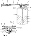
- the inlet valve body or the O-ring seal 10 is permanently displaced from the inlet line 3 when pressurized gas is applied, as shown in FIG Fig. 3 and Fig. 3a represented by the position 10a.
- the O-ring seal 10 is also shown in its originally closed position, so that the "sliding movement" becomes clear.
- the inlet line 3 merges into an inlet connection 18 arranged centrally to the container opening and arranged inside the latter.
- the inlet nozzle or, in its continuation, the container opening annularly surround the container-side partial length of the outlet line 4 extending into the riser pipe 16.
- Fig. 2 also shows the breakdown assistance system, as in the Fig. 1 is shown, but here already the screw cap 6 is removed on the intake pipe 3 and the exhaust valve 13 is already screwed onto the tire valve 12, whereby the exhaust valve is opened.
- the open position of the valve body 14 shows the Fig. 2a enlarged again.
- Fig. 3 shows the same breakdown assistance system, but here the compressor line 19 is already connected to the inlet line 3, the O-ring seal 10 is permanently displaced by pressurized gas and a part of the sealant 8 is already through the reaching under the sealant level riser 16, the distribution unit 2, the exhaust duct 4 and the valves 13 and 12 are expelled in the tire.
Description
Die Erfindung betrifft ein Pannenhilfesystem zum Abdichten und Aufpumpen von Kraftfahrzeugreifen, wobei das Pannenhilfesystem eine Druckgasquelle, vorzugsweise einen Kompressor umfasst, sowie einen Behälter für ein in den Kraftfahrzeugreifen einfüllbares selbsttätiges Dichtmittel. Der Behälter weist eine an seinem oberen Ende befindlichen Behälteröffnung auf, sowie eine mit dem Behälter verbundene Verteilereinheit für Dichtmittel und Druckgas. Die Verteilereinheit ist als Deckel für die Behälteröffnung ausgebildet und ist sowohl mit einer an die Druckgasquelle anschließbaren Einlassleitung als auch mit einer an den Kraftfahrzeugreifen anschließbaren Auslassleitung (4) versehen. Die Einlassleitung weist ein Einlassventil mit einem Einlassventilkörper auf.The invention relates to a breakdown assistance system for sealing and inflating motor vehicle tires, wherein the breakdown assistance system comprises a compressed gas source, preferably a compressor, and a container for a self-sealing means which can be filled into the motor vehicle tire. The container has a container opening located at its upper end, and a distributor unit for sealant and compressed gas connected to the container. The distributor unit is designed as a lid for the container opening and is provided both with an inlet line which can be connected to the compressed gas source and with an outlet line (4) which can be connected to the motor vehicle tire. The intake passage has an intake valve with an intake valve body.
Bei Reifenpannen besteht in aller Regel das Problem, dass - wie beispielsweise bei einem PKW bisher üblich - ein gefüllter und auf einer Felge montierter Reservereifen mitgeführt werden muss, der dann anstelle des Rades mit dem defekten Reifen montiert wird, wonach der defekte Reifen in dem für den Reservereifen vorgesehenen Stauraum im Fahrzeug befestigt werden und später einer Reparatur zugeführt werden muss. Hierzu ist es nicht nur oft notwendig, ein beladenes Fahrzeug auszuräumen, um an den entsprechenden Stauraum zu gelangen, sondern es muss auch das Fahrzeug selbst mit Wagenhebern aufgebockt und eine umständliche Reparaturarbeit durchgeführt werden.In the case of flat tires there is usually the problem that - as for example in a car so far - a filled and mounted on a rim spare tire must be carried, which is then mounted instead of the wheel with the defective tire, after which the defective tire in the for the spare tire provided storage space to be fixed in the vehicle and later a repair must be supplied. For this it is not only often necessary to clear a loaded vehicle to get to the appropriate storage space, but it must also jacked up the vehicle itself with jacks and a cumbersome repair work is performed.
Bei Fahrzeugen, die nicht mit schlauchlosen Reifen versehen sind, wie etwa bei Fahrrädern, ist es bei einer Reifenpanne nötigt, mit umfangreichem Werkzeug nach der Montage des Reifens den Mantel von der Felge zu entfernen, den Schlauch zu entnehmen und mit entsprechend mitgeführtem Reparaturmaterial zu flicken. Danach muss der Reifen bzw. der Schlauch oft mehrfach aufgepumpt werden, um eine einigermaßen sichere Weiterfahrt zu gewährleisten. Neben der schwierigen Reparaturtätigkeit besteht bei dem bisher bekannten Verfahren der Nachteil, dass die notwendigen Reparaturmaterialien, wie etwa eine entsprechende Pumpe sowie Hebe- und Schraubwerkzeuge, sowie bei nächtlichen Pannen nötige Beleuchtungskörper, in oder bei den entsprechenden Fahrzeugen nur unvollständig oder gar nicht vorhanden oder an den unterschiedlichsten Stellen verstaut sind und lange gesucht werden müssen.In vehicles that are not provided with tubeless tires, such as bicycles, it is necessary in a flat tire to remove with extensive tools after installation of the tire, the jacket of the rim, remove the hose and mend with appropriately entrained repair material , After that, the tire has to be or the hose often be inflated several times to ensure a reasonably safe onward journey. In addition to the difficult repair activity is in the previously known method, the disadvantage that the necessary repair materials, such as a corresponding pump and lifting and screwing tools, as well as necessary for nightly mishap lighting fixtures, in or on the corresponding vehicles incomplete or not available or at stowed in different places and have to be searched for a long time.
Um diese Nachteile zu vermeiden, sind bereits Reparatursätze bekannt, die einen Kompressor, ein im Reifen koagulierendes Dichtmittel, meistens ein Latexmilch-Gemisch, die entsprechenden Verbindungsschläuche und die notwendigen Kabelanschlüsse zur Energiezufuhr sowie Schalter, Manometer und Bedienelement beinhalten und somit einen ständig einsetzbaren und vollständigen Reparatursatz bereitstellen, mit dem auf das Mitführen eines auf eine Felge aufgezogenen Reserverades oder auf die ständige Kontrolle anderer Reparaturmaterialien wie Schläuche, verschiedene Werkzeugschlüssel, Wagenheber etc. verzichtet werden kann.To avoid these disadvantages, repair kits are already known, which include a compressor, a coagulating in the tire sealant, usually a latex milk mixture, the corresponding connecting hoses and the necessary cable connections for power supply and switch, pressure gauge and control element and thus a constantly deployable and complete Provide a repair kit that can be dispensed with the carry on a rim mounted spare wheel or the constant control of other repair materials such as hoses, various tool wrench, jack etc.
Die Bedienung solcher Reparatursätze ist aber auch nicht ganz einfach. So müssen je nach Betriebszustand zunächst Dichtmittelbehälter und diverse Schlauchverbindungen angeschlossen oder umgebaut werden. Die meisten Reparatursätze sind nämlich auch gut dazu geeignet, ohne Dichtmitteleinsatz lediglich zum Aufblasen von Reifen, Schlauchbooten, Luftmatratzen, etc. eingesetzt zu werden. Aufgrund der heutzutage nur noch selten auftretenden Reifenpannen werden die Reparatursätze in der Regel häufiger für solche Freizeitzwecke gebraucht als für Notfälle. Wenn dies dann aber doch geschieht, befindet sich der Nutzer in ungewohnter und ungeübter Situation.The operation of such repair kits is not easy. Depending on the operating condition, sealant containers and various hose connections must first be connected or rebuilt. In fact, most repair kits are also well suited to be used without the use of sealant only for inflating tires, inflatable boats, air mattresses, etc. Due to the now rarely occurring punctures the repair kits are usually used more often for such recreational purposes than for emergencies. But when this happens, the user is in an unfamiliar and inexperienced situation.
Ein Problem bei der Nutzung in Reparaturfällen entsteht zum Beispiel, wenn der Dichtmittelbehälter fälschlicherweise mit seinem Schlauch bzw. dem zugehörigen Anschlussstück zuerst mit dem Reifenventil verbunden wird und noch ein Restdruck im Reifen vorherrscht. Der in den Behälter einströmende Restdruck kann dazu führen, dass Dichtmittel aus dem Behälter in die Umgebung austritt, sofern Sicherungskappen auf der Einlassseite der Verteilereinheit bereits gelöst oder gar nicht vorhanden sind, oder dazu, dass Dichtmittel in Richtung eines bereits mit der Verteilereinheit verbundenen, aber noch nicht eingeschalteten Kompressors befördert wird und dort Ventile verklebt.A problem with the use in repair cases arises, for example, when the sealant container is falsely connected with its hose or the associated connector first with the tire valve and still prevails a residual pressure in the tire. The residual pressure flowing into the container can cause sealant to escape from the container into the environment, provided that safety caps on the Inlet side of the distributor unit are already solved or not present, or that sealant is transported in the direction of already connected to the distribution unit, but not yet switched compressor and there glued valves.
Zur Erleichterung der Handhabung der Geräte/Reparatursätze in solchen unterschiedlichen Anwendungen sind im Stand der Technik bereits Lösungen bekannt, die im Wesentlichen ein vereinfachtes Umschalten von der einen auf die andere Betriebsart beinhalten. So offenbart die
Ausgehend von diesem Stand der Technik bestand für die Erfindung die Aufgabe, eine Vorrichtung zum Abdichten und Aufpumpen aufblasbarer Gegenstände bereitzustellen, die eine sichere Verbindung zwischen Dichtmittelbehälter bzw. Ventil- und Verteilereinheit bereitstellt, die eine vereinfachte Anwendung in der einen oder anderen Betriebsart erlaubt, die bei fehlerhafter Anschlussreihenfolge im Reifen vorhandenen Restdruck problemlos toleriert und somit sicher zu handhaben ist und die insbesondere eine möglichst einfache Konstruktion bei gleichzeitig robuster Ausführung aufweist und dazu einfach und preisgünstig herzustellen ist.Based on this prior art, the object of the invention was to provide a device for sealing and inflating inflatable objects, which provides a secure connection between the sealant container or valve and distributor unit, which allows a simplified application in one or the other mode, the is tolerated easily in faulty connection order in the tire residual pressure and thus safe to handle and in particular has the simplest possible construction with a rugged design and this is easy and inexpensive to manufacture.
Gelöst wird diese Aufgabe durch die Merkmale des Hauptanspruchs. Weitere vorteilhafte Ausbildungen sind in den Unteransprüchen offenbart.This object is achieved by the features of the main claim. Further advantageous embodiments are disclosed in the subclaims.
Dabei weist die Auslassleitung an ihrem reifenseitigen Ende ein Auslassventil auf, welches durch Anschluss an ein Reifenventil, ein so genanntes Schraderventil, geöffnet wird, wobei eine über das Auslassventil erfolgende, also reifenseitige, d.h. durch Restdruck im Reifen erfolgende Erhöhung des Innendrucks im Behälter den Einlassventilkörper schließend auf seinen Dichtsitz presst. Dadurch wird der Behälter kompressorseitig sicher und "selbstverstärkend" geschlossen, so dass mit der erfindungsgemäßen Ausbildung ein ungewollter Austritt von Dichtmittel ebenso sicher vermieden wird wie das Einpressen von Dichtmittel in empfindliche Kompressorbereiche.In this case, the exhaust pipe at its tire-side end to an exhaust valve, which is opened by connection to a tire valve, called a Schrader valve, with a taking place via the exhaust valve, so tire side, i. By increasing residual pressure in the tire, the internal pressure in the container increases and the inlet valve body closes and presses against its sealing seat. As a result, the container is closed on the compressor side safely and "self-reinforcing", so that with the formation of the invention an unwanted leakage of sealant is just as reliably avoided as the pressing of sealant in sensitive compressor areas.
Dabei wird eine Rückflußsicherung in Richtung Kompressor und dort angeordneter Leitungs- und Ventilbauteile dadurch realisiert, dass ein Ventilkörper, z.B. ein verschiebarer O-Ring, im Falle eines Druckaufbaus in der Dichtmittelflasche, hervorgerufen durch eine Druckquelle auf der Auslaßseite (z.B. Reifen mit Restdruck), den Einlaßkanal / die Einlaßöffnung der Dichtmittelflasche verschließt.In this case, a return flow in the direction of the compressor and there arranged line and valve components is realized in that a valve body, e.g. a slidable O-ring, in the event of pressure build-up in the sealant bottle caused by a pressure source on the outlet side (e.g., residual pressure tires), closes the inlet port / port of the sealant bottle.
Bei Beaufschlagung mit Druckgas aus der Druckquelle, d.h. sobald der Druck durch die Druckquelle größer wird als der Druck innerhalb der Dichtmittelflasche, öffnet das somit als "Rückflußsicherungsventil" aufgebaute Einlassventil den Einlaßkanal / die Einlaßöffnung wieder und das Pannenhilfesystem kann, wie vorgesehen, benutzt werden.Upon application of compressed gas from the pressure source, i. as soon as the pressure through the pressure source becomes greater than the pressure within the sealant bottle, the inlet valve thus constructed as a "backflow valve" reopens the inlet port / inlet port and the breakdown assistance system can be used as intended.
Bei ordnungsgemäßem Gebrauch, bei dem die Druckbeaufschlagung der Dichtmittelflasche nur von der Einlaßseite erfolgt, hat das "Rückflußsicherungsventil" quasi keine Funktion. Im Lieferzustand ist der Einlaßkanal in diesem Falle nicht vom "Rückflußsicherungsventil" verschlossen. Der Verschluß der Flasche wird durch die Verschlußkappe / Schraubdeckel gewährleistet.When used properly, in which the pressurization of the sealant bottle takes place only from the inlet side, the "backflow valve" has virtually no function. As delivered, the inlet channel is not closed by the "reflux valve" in this case. The closure of the bottle is ensured by the cap / screw cap.
Eine vorteilhafte Ausführung besteht darin, dass das Einlassventil eine geschlossene Ausgangsstellung aufweist und das Einlassventil bei Beaufschlagung mit Druckgas aus der Druckquelle die Einlassleitung (3) zum Behälterinnenraum öffnet. Eine solche Ausbildung ist als Alternative zu der grundsätzlich "geöffneten" Anordnung des Einlassventils dann geeignet, wenn man z.B. aus Kostengründen nur ein Ventil auf der Einlassseite vorsehen und einen möglichst einfach konstruierten Schraubdeckel vorsehen will.An advantageous embodiment is that the inlet valve has a closed starting position and the inlet valve when pressurized gas the pressure source opens the inlet line (3) to the container interior. Such a design is suitable as an alternative to the basically "open" arrangement of the inlet valve when, for example, for cost reasons, only provide a valve on the inlet side and provide a screw cap designed as simple as possible.
Eine weitere vorteilhafte Ausführung besteht darin, dass der Einlassventilkörper bei Beaufschlagung mit Druckgas aus der Einlassleitung bleibend verschiebbar ist, insbesondere darin, dass die Einlassleitung in einen mit der Behälteröffnung kommunizierenden Einlassstutzen führt, welcher als Ringraum-Leitung ausgebildet ist, wobei der Einlassventilkörper aus einer in die Ringraum-Leitung eingesetzte O-Ring-Dichtung besteht.A further advantageous embodiment consists in that the inlet valve body is permanently displaceable when pressurized gas is applied from the inlet line, in particular in that the inlet line leads into an inlet connection communicating with the container opening, which is designed as an annular space line, wherein the inlet valve body consists of an in the annulus line is inserted O-ring seal.
Durch eine solche Ausbildung ergeben sich eine überaus kompakte Bauweise und eine sehr einfache Herstellung aus Normbauteilen und mit nur wenigen einfachen Fertigungsschritten wie Bohren oder Fräsen oder Spritzgießen. Das Öffnen des Einlassventils und des Auslassventils erfolgt dabei automatisch und sicher.Such a design results in a very compact design and a very simple production of standard components and with only a few simple manufacturing steps such as drilling or milling or injection molding. The opening of the inlet valve and the exhaust valve is carried out automatically and safely.
Die weiteren vorteilhaften Ausbildungen lassen sich am besten anhand der nachfolgend beschriebenen Ausführungsbeispiele erläutern. Es zeigen
- Fig. 1
- ein erfindungsgemäßes Pannenhilfesystems mit der zugehörige Verteilereinheit und den Einlass- und Auslassventilen im Schnitt
- Fig. 1a
- eine vergrößerte Darstellung des noch nicht an das Reifenventil angeschlossenen Auslassventils der
Fig. 1 - Fig. 1b
- eine vergrößerte Darstellung der Verteilereinheit der
Fig. 1 mit in Schließstellung befindlichem Einlassventilkörper, ausgebildet als O-Ring-Dichtung - Fig. 2
- das erfindungsgemäße Pannenhilfesystem gem.
Fig. 1 , bereits angeschlossen an das Reifenventil - Fig. 2a
- eine vergrößerte Darstellung des an das Reifenventil angeschlossenen Auslassventils der
Fig. 2 - Fig. 3
- das erfindungsgemäße Pannenhilfesystem gem.
Fig. 1 und2 , bereits angeschlossen an das Reifenventil und an eine Druckquelle/Kompressor - Fig. 3a
- eine vergrößerte Darstellung der Verteilereinheit der
Fig. 3 mit bleibend verschobenem Einlassventilkörper, ausgebildet als O-Ring-Dichtung
- Fig. 1
- an inventive breakdown assistance system with the associated distribution unit and the intake and exhaust valves in section
- Fig. 1a
- an enlarged view of the exhaust valve not yet connected to the tire valve
Fig. 1 - Fig. 1b
- an enlarged view of the distribution unit of
Fig. 1 with inlet valve body located in the closed position, designed as an O-ring seal - Fig. 2
- the breakdown assistance system according to the invention.
Fig. 1 , already connected to the tire valve - Fig. 2a
- an enlarged view of the exhaust valve connected to the tire valve
Fig. 2 - Fig. 3
- the breakdown assistance system according to the invention.
Fig. 1 and2 , already connected to the tire valve and to a pressure source / compressor - Fig. 3a
- an enlarged view of the distribution unit of
Fig. 3 with permanently displaced inlet valve body, designed as O-ring seal
Die
Die Verteilereinheit ist dabei als Deckel oder Verschluss für die Behälteröffnung 5 ausgebildet. Die
Die Verteilereinheit 2 ist über ein Schraubgewinde 7 mit dem flaschenförmigen Dichtmittelbehälter 1 verbunden. Im Dichtmittelbehälter befindet sich ein in den aufblasbaren Gegenstand einfüllbares selbsttätiges Dichtmittel 8.The
Die Auslassleitung 4 des Behälters 1 führt zum Kraftfahrzeugreifen und besteht aus einem flexiblen und luftdichten Schlauch aus Gummi. Natürlich können hier auch Kunststoffe und/oder Gewebematerialien als Schlauchmaterial eingesetzt werden.The
Die Einlassleitung weist ein Einlassventil mit einem Einlassventilkörper 10 auf und ist so gestaltet, dass die Einlassleitung 3 in einen mit der Behälteröffnung kommunizierenden Einlassstutzen führt, welcher als Ringraum-Leitung 9 ausgebildet ist, wobei der Einlassventilkörper aus einer in die Ringraum-Leitung 9 eingesetzte O-Ring-Dichtung 10 besteht. Der als O-Ring-Dichtung 10 ausgebildete Einlassventilkörper öffnet bei Beaufschlagung mit Druckgas aus der Druckquelle die Einlassleitung 3 zum Behälterinnenraum 11. Im Detail zeigt dies auch noch einmal die
Die Auslassleitung 4 weist an ihrem reifenseitigen Ende ein durch Anschluss an ein Reifenventil 12 , siehe
Das bekannte in Kraftfahrzeugen eingesetzte Schraderventil ist so aufgebaut, dass beim Aufstecken des eines Pumpenkopfes, eines Manometers oder eben auch des hier gezeigten Auslassventils 13 des Pannenhilfesystems im Schraderventil ein Stift heruntergedrückt wird, der letzteres ebenso öffnet wie auch das entsprechend konstruiertes Auslassventil 13 eines Pannenhilfesystems. Das Auslassventil 13 weist hierzu einen in genannter Weise mit dem Stift des Schraderventils zusammenwirkenden und mit einem stiftartigen Vorsprung versehenen Ventilkörper 14 auf, der gegen eine Feder 15 in die Öffnungsstellung gedrückt werden kann. Diese Öffnungsstellung des Ventilkörpers 14 zeigt die
Da der Behälter 1 ist in dieser Ausführung im Betriebszustand aufrecht angeordnet ist, steht die Auslassleitung 4 mit einem in den Behälterinnenraum 11 hineinragenden und bis unter den Dichtmittelspiegel reichenden Steigrohr 16 in Verbindung, wobei letzteres durch ein Gewicht 17 in seiner Position gehalten wird..Since the
Das Einlassventil bzw. die O-Ring-Dichtung 10 weist eine geschlossene Ausgangsstellung auf, bei der eine über das geöffnete Auslassventil 13 evtl. erfolgende Erhöhung des Innendrucks im Behälter durch einen noch im Reifen vorhandenen Restdruck den Einlassventilkörper bzw. die O-Ring-Dichtung 10 schließend auf seinen Dichtsitz presst und somit den Behälter 1 kompressorseitig fest und selbstverstärkend schließt. Diese Stellung des Einlassventilkörpers 10 ist in der
Der Einlassventilkörper bzw. die O-Ring-Dichtung 10 wird bei Beaufschlagung mit Druckgas aus der Einlassleitung 3 bleibend verschoben, wie dies in
Die Einlassleitung 3 geht in einen zentrisch zur Behälteröffnung angeordneten und innerhalb letzterer angeordneten Einlassstutzen 18 über. Der Einlassstutzen bzw. in seiner Fortsetzung die Behälteröffnung umgeben ringförmig die in das Steigrohr 16 reichende bzw. übergehende behälterseitige Teillänge der Auslassleitung 4.The
Auch die
- 11
- Behältercontainer
- 22
- Verteilereinheitdistribution unit
- 33
- Einlassleitunginlet line
- 44
- Auslassleitungoutlet pipe
- 55
- Behälteröffnungcontainer opening
- 66
- Schraubdeckelscrew
- 77
- Schraubgewindescrew thread
- 88th
- Dichtmittelsealant
- 99
- Ringraum-LeitungAnnulus line
- 1010
- Einlassventilkörper / O-Ring-DichtungInlet valve body / O-ring seal
- 1111
- BehälterinnenraumContainer interior
- 1212
- Reifenventiltire valve
- 1313
- Auslassventiloutlet valve
- 1414
- Ventilkörper des AuslassventilsValve body of the exhaust valve
- 1515
- Federfeather
- 1616
- Steigrohrriser
- 1717
- Gewicht am Ende des SteigrohresWeight at the end of the riser
- 1818
- Einlassstutzeninlet port
- 1919
- Kompressorleitungcompressor line
Claims (8)
- Breakdown assistance system for sealing and inflating motor vehicle tyres, wherein the breakdown assistance system comprises the following means:- a pressurized gas source, preferably a compressor,- a container (1) for a self-acting sealant (8) which can be introduced into the motor vehicle tyre, wherein the container (1) has a container opening (5) situated at its upper end,- a distributor unit (2), which is connected to the container (1), for sealant and pressurized gas, wherein the distributor unit (2) is designed as a cover for the container opening (5) and is equipped with an inlet line (3), which is connectable to the pressurized gas source, and with an outlet line (4), which is connectable to the motor vehicle tyre,- and wherein the inlet line (3) has an inlet valve with an inlet valve body (10), wherein the outlet line (4) has, at its tyre-side end, an outlet valve (13) which opens as a result of connection to a tyre valve (12),- wherein the inlet valve opens the inlet channel as soon as the pressure effected by the pressure source is higher than the pressure within the container or the sealant bottle,characterized in that, in the event of an increase, taking place via the outlet valve (13), of the internal pressure in the container, the inlet valve closes the container at the compressor side by virtue of the inlet valve body (10) being pressed with a closing action onto its sealing seat.
- Breakdown assistance system according to Claim 1, in which the inlet valve has an open initial position and the inlet valve, after closure, opens the inlet line (3) to the container interior again when charged with pressurized gas from the pressure source.
- Breakdown assistance system according to Claim 1, in which the inlet valve has a closed initial position and the inlet valve opens the inlet line (3) to the container interior when charged with pressurized gas from the pressure source.
- Breakdown assistance system according to one of Claims 1 to 3, in which the inlet valve body (10) can be displaced permanently out of the inlet line (3) when acted on with pressurized gas.
- Breakdown assistance system according to one of Claims 1 to 4, in which the inlet line (3) leads into an inlet connector which communicates with the container opening and which is formed as a ring-shaped chamber line (9), and the inlet valve body (10) is composed of an O-ring seal inserted into the ring-shaped chamber line.
- Breakdown assistance system according to one of Claims 1 to 5, in which the container (1) is arranged upright, and the outlet line (4) is connected to a riser pipe (16) which projects into the container interior (11) and which extends as far as below the sealant surface.
- Breakdown assistance system according to one of Claims 1 to 6, in which the inlet line (3) leads into an inlet connector (18) which is arranged centrally with respect to the container opening and which communicates with the latter, wherein the inlet connector surrounds, in ring-shaped fashion, a partial length of the outlet line (4).
- Breakdown assistance system according to Claim 7, in which the inlet connector (18) is formed within the distributor unit (2) and/or within the container opening.
Applications Claiming Priority (2)
| Application Number | Priority Date | Filing Date | Title |
|---|---|---|---|
| DE201210100636 DE102012100636A1 (en) | 2012-01-26 | 2012-01-26 | Return protection |
| PCT/EP2013/050131 WO2013110486A1 (en) | 2012-01-26 | 2013-01-07 | Backflow protector |
Publications (2)
| Publication Number | Publication Date |
|---|---|
| EP2807018A1 EP2807018A1 (en) | 2014-12-03 |
| EP2807018B1 true EP2807018B1 (en) | 2018-10-24 |
Family
ID=47521026
Family Applications (1)
| Application Number | Title | Priority Date | Filing Date |
|---|---|---|---|
| EP13700031.1A Active EP2807018B1 (en) | 2012-01-26 | 2013-01-07 | Backflow protector |
Country Status (5)
| Country | Link |
|---|---|
| EP (1) | EP2807018B1 (en) |
| JP (1) | JP6370224B2 (en) |
| CN (1) | CN104080594B (en) |
| DE (1) | DE102012100636A1 (en) |
| WO (1) | WO2013110486A1 (en) |
Cited By (1)
| Publication number | Priority date | Publication date | Assignee | Title |
|---|---|---|---|---|
| US11794426B2 (en) | 2021-06-30 | 2023-10-24 | Illinois Tool Works Inc. | Flat tire repair device |
Families Citing this family (4)
| Publication number | Priority date | Publication date | Assignee | Title |
|---|---|---|---|---|
| DE102015203972A1 (en) * | 2015-03-05 | 2016-09-08 | Continental Reifen Deutschland Gmbh | Portable repair kit |
| TWI745753B (en) * | 2019-09-24 | 2021-11-11 | 周文三 | Anti-spray joint structure for gas nozzle of tire of vehicle and connection hose of vehicle air compressor |
| TWI729506B (en) * | 2019-09-24 | 2021-06-01 | 周文三 | Check connector structure for a gas nozzle of a tire of vehicle and an air compressor |
| TWI728479B (en) * | 2019-09-25 | 2021-05-21 | 周文三 | Check structure for gas nozzle of ire of vehicle and air compressor |
Citations (11)
| Publication number | Priority date | Publication date | Assignee | Title |
|---|---|---|---|---|
| US3429330A (en) | 1964-02-04 | 1969-02-25 | Halkey Roberts Corp | Mouthpiece for orally operated valve |
| WO2005084968A2 (en) | 2004-02-27 | 2005-09-15 | Tek S.R.L. | Container for sealing liquid for repairing inflatable articles, in particular tyres, and repair kit featuring such a container |
| WO2005085028A1 (en) | 2004-02-27 | 2005-09-15 | Tek S.R.L. | Kit for inflating and repairing inflatable articles, in particular tyres |
| DE202006001994U1 (en) | 2006-02-07 | 2007-06-06 | Stehle, Michael | Device for dispensing tire sealant from a container |
| DE102006059479A1 (en) | 2006-02-07 | 2007-08-09 | Michael Stehle | Device for discharging air and/or tire sealant from a container useful in automotive industry, comprises a fastening element, a pressure source, a withdrawal opening for discharging air and/or tire sealant, and an inlet closure |
| JP2008002513A (en) | 2006-06-20 | 2008-01-10 | Bridgestone Corp | Valve connector and sealing pumping up device |
| WO2008035163A2 (en) | 2006-09-18 | 2008-03-27 | Tek Global S.R.L. | Kit for repairing and inflating inflatable articles |
| JP2009056681A (en) | 2007-08-31 | 2009-03-19 | Honda Motor Co Ltd | Tire puncture repair apparatus |
| DE102008015022B3 (en) | 2008-03-19 | 2009-11-05 | Continental Aktiengesellschaft | Roadside Assistance System |
| WO2010078626A1 (en) | 2009-01-07 | 2010-07-15 | Trydel Research Pty. Ltd. | Apparatus for repairing and inflating of damaged inflatable articles |
| US20110041951A1 (en) | 2009-08-21 | 2011-02-24 | Tek Global S.R.L. | Sealing fluid canister, and repair kit comprising such a canister |
Family Cites Families (2)
| Publication number | Priority date | Publication date | Assignee | Title |
|---|---|---|---|---|
| DE20122862U1 (en) | 2001-02-13 | 2008-09-11 | Doukas Ag | Device for dispensing tire sealant |
| JP2012006347A (en) * | 2010-06-28 | 2012-01-12 | Sumitomo Rubber Ind Ltd | Method of connecting kit for fixing flat tire |
-
2012
- 2012-01-26 DE DE201210100636 patent/DE102012100636A1/en not_active Withdrawn
-
2013
- 2013-01-07 CN CN201380006896.8A patent/CN104080594B/en active Active
- 2013-01-07 EP EP13700031.1A patent/EP2807018B1/en active Active
- 2013-01-07 WO PCT/EP2013/050131 patent/WO2013110486A1/en active Application Filing
- 2013-01-07 JP JP2014553664A patent/JP6370224B2/en active Active
Patent Citations (12)
| Publication number | Priority date | Publication date | Assignee | Title |
|---|---|---|---|---|
| US3429330A (en) | 1964-02-04 | 1969-02-25 | Halkey Roberts Corp | Mouthpiece for orally operated valve |
| WO2005084968A2 (en) | 2004-02-27 | 2005-09-15 | Tek S.R.L. | Container for sealing liquid for repairing inflatable articles, in particular tyres, and repair kit featuring such a container |
| WO2005085028A1 (en) | 2004-02-27 | 2005-09-15 | Tek S.R.L. | Kit for inflating and repairing inflatable articles, in particular tyres |
| DE202006001994U1 (en) | 2006-02-07 | 2007-06-06 | Stehle, Michael | Device for dispensing tire sealant from a container |
| DE102006059479A1 (en) | 2006-02-07 | 2007-08-09 | Michael Stehle | Device for discharging air and/or tire sealant from a container useful in automotive industry, comprises a fastening element, a pressure source, a withdrawal opening for discharging air and/or tire sealant, and an inlet closure |
| JP2008002513A (en) | 2006-06-20 | 2008-01-10 | Bridgestone Corp | Valve connector and sealing pumping up device |
| WO2008035163A2 (en) | 2006-09-18 | 2008-03-27 | Tek Global S.R.L. | Kit for repairing and inflating inflatable articles |
| JP2009056681A (en) | 2007-08-31 | 2009-03-19 | Honda Motor Co Ltd | Tire puncture repair apparatus |
| DE102008015022B3 (en) | 2008-03-19 | 2009-11-05 | Continental Aktiengesellschaft | Roadside Assistance System |
| WO2010078626A1 (en) | 2009-01-07 | 2010-07-15 | Trydel Research Pty. Ltd. | Apparatus for repairing and inflating of damaged inflatable articles |
| US20110290372A1 (en) | 2009-01-07 | 2011-12-01 | Try-Del Research Pty. Ltd. | Apparatus for repairing and inflating of damaged inflatable articles |
| US20110041951A1 (en) | 2009-08-21 | 2011-02-24 | Tek Global S.R.L. | Sealing fluid canister, and repair kit comprising such a canister |
Cited By (1)
| Publication number | Priority date | Publication date | Assignee | Title |
|---|---|---|---|---|
| US11794426B2 (en) | 2021-06-30 | 2023-10-24 | Illinois Tool Works Inc. | Flat tire repair device |
Also Published As
| Publication number | Publication date |
|---|---|
| JP6370224B2 (en) | 2018-08-08 |
| CN104080594B (en) | 2016-07-06 |
| WO2013110486A1 (en) | 2013-08-01 |
| DE102012100636A1 (en) | 2013-08-01 |
| EP2807018A1 (en) | 2014-12-03 |
| JP2015508349A (en) | 2015-03-19 |
| CN104080594A (en) | 2014-10-01 |
Similar Documents
| Publication | Publication Date | Title |
|---|---|---|
| EP2217431B1 (en) | Device having a valve unit for sealing and pumping up inflatable objects | |
| DE602005002034T2 (en) | CONTAINER FOR SEALING LIQUID FOR REPAIRING INFLATABLE ARTICLES, ESPECIALLY TIRES AND SUCH A REPAIR KIT CONTAINING SUCH CONTAINER | |
| EP2807018B1 (en) | Backflow protector | |
| EP2276624B1 (en) | Car breakdown aide system | |
| DE202005021981U1 (en) | Set for inflating and repairing inflatable articles, in particular tires | |
| EP3383630B1 (en) | Device for sealing and inflating motor vehicle tyres | |
| WO2009065653A1 (en) | Apparatus comprising a switching mark for sealing and pumping up inflatable objects | |
| DE102015119917A1 (en) | Method and device for dispensing a means for sealing an inflatable article | |
| WO2008151870A2 (en) | Tire sealing device | |
| DE10110713C2 (en) | Hand pump with automatic and hand pumping function | |
| DE102007003667B4 (en) | Device for sealing and inflating inflatable objects | |
| DE102015220060A1 (en) | Tire valve connection | |
| EP2212101B1 (en) | Apparatus comprising a plug-in connection for sealing and pumping up inflatable objects | |
| EP3068616B1 (en) | Device for sealing and inflating inflatable objects | |
| DE112016005755B4 (en) | REPAIR DEVICE AND PROCEDURE | |
| EP3068615B1 (en) | Device for sealing and inflating inflatable articles with attitude valve | |
| EP1275532B1 (en) | Tire valve for tire with runflat-tube | |
| DE2843605A1 (en) | Pneumatic cylinder inflation valve - has test valve at end in line with sliding pin for inflator and manometer one side | |
| DE202004009114U1 (en) | Vehicle tire sealing system is fitted with retarder which retards flow of sealant after at least its first operation | |
| DE306916C (en) | ||
| DE2649057A1 (en) | Safety pneumatic tyre is filled with balls - contg. air or foam to give continued running after puncture | |
| DE2947218A1 (en) | Cushioning equipment for securing rail wagon load - has compressed air supply with valve screwing onto nipple, and safety valve fitting | |
| DE1505177A1 (en) | Device for inflating inflatable objects | |
| DE202008005408U1 (en) | Roadside Assistance System | |
| DE102014109358A1 (en) | Motor vehicle with a tire measuring and filling device |
Legal Events
| Date | Code | Title | Description |
|---|---|---|---|
| PUAI | Public reference made under article 153(3) epc to a published international application that has entered the european phase |
Free format text: ORIGINAL CODE: 0009012 |
|
| 17P | Request for examination filed |
Effective date: 20140826 |
|
| AK | Designated contracting states |
Kind code of ref document: A1 Designated state(s): AL AT BE BG CH CY CZ DE DK EE ES FI FR GB GR HR HU IE IS IT LI LT LU LV MC MK MT NL NO PL PT RO RS SE SI SK SM TR |
|
| DAX | Request for extension of the european patent (deleted) | ||
| RIC1 | Information provided on ipc code assigned before grant |
Ipc: B29L 30/00 20060101ALN20180614BHEP Ipc: B29C 73/16 20060101AFI20180614BHEP |
|
| GRAP | Despatch of communication of intention to grant a patent |
Free format text: ORIGINAL CODE: EPIDOSNIGR1 |
|
| STAA | Information on the status of an ep patent application or granted ep patent |
Free format text: STATUS: GRANT OF PATENT IS INTENDED |
|
| RIC1 | Information provided on ipc code assigned before grant |
Ipc: B29C 73/16 20060101AFI20180625BHEP Ipc: B29L 30/00 20060101ALN20180625BHEP |
|
| INTG | Intention to grant announced |
Effective date: 20180720 |
|
| GRAS | Grant fee paid |
Free format text: ORIGINAL CODE: EPIDOSNIGR3 |
|
| GRAA | (expected) grant |
Free format text: ORIGINAL CODE: 0009210 |
|
| STAA | Information on the status of an ep patent application or granted ep patent |
Free format text: STATUS: THE PATENT HAS BEEN GRANTED |
|
| AK | Designated contracting states |
Kind code of ref document: B1 Designated state(s): AL AT BE BG CH CY CZ DE DK EE ES FI FR GB GR HR HU IE IS IT LI LT LU LV MC MK MT NL NO PL PT RO RS SE SI SK SM TR |
|
| REG | Reference to a national code |
Ref country code: CH Ref legal event code: EP |
|
| REG | Reference to a national code |
Ref country code: IE Ref legal event code: FG4D Free format text: LANGUAGE OF EP DOCUMENT: GERMAN |
|
| REG | Reference to a national code |
Ref country code: AT Ref legal event code: REF Ref document number: 1056168 Country of ref document: AT Kind code of ref document: T Effective date: 20181115 |
|
| REG | Reference to a national code |
Ref country code: DE Ref legal event code: R096 Ref document number: 502013011410 Country of ref document: DE |
|
| REG | Reference to a national code |
Ref country code: NL Ref legal event code: MP Effective date: 20181024 |
|
| REG | Reference to a national code |
Ref country code: LT Ref legal event code: MG4D |
|
| PG25 | Lapsed in a contracting state [announced via postgrant information from national office to epo] |
Ref country code: NL Free format text: LAPSE BECAUSE OF FAILURE TO SUBMIT A TRANSLATION OF THE DESCRIPTION OR TO PAY THE FEE WITHIN THE PRESCRIBED TIME-LIMIT Effective date: 20181024 |
|
| PG25 | Lapsed in a contracting state [announced via postgrant information from national office to epo] |
Ref country code: LT Free format text: LAPSE BECAUSE OF FAILURE TO SUBMIT A TRANSLATION OF THE DESCRIPTION OR TO PAY THE FEE WITHIN THE PRESCRIBED TIME-LIMIT Effective date: 20181024 Ref country code: HR Free format text: LAPSE BECAUSE OF FAILURE TO SUBMIT A TRANSLATION OF THE DESCRIPTION OR TO PAY THE FEE WITHIN THE PRESCRIBED TIME-LIMIT Effective date: 20181024 Ref country code: IS Free format text: LAPSE BECAUSE OF FAILURE TO SUBMIT A TRANSLATION OF THE DESCRIPTION OR TO PAY THE FEE WITHIN THE PRESCRIBED TIME-LIMIT Effective date: 20190224 Ref country code: NO Free format text: LAPSE BECAUSE OF FAILURE TO SUBMIT A TRANSLATION OF THE DESCRIPTION OR TO PAY THE FEE WITHIN THE PRESCRIBED TIME-LIMIT Effective date: 20190124 Ref country code: LV Free format text: LAPSE BECAUSE OF FAILURE TO SUBMIT A TRANSLATION OF THE DESCRIPTION OR TO PAY THE FEE WITHIN THE PRESCRIBED TIME-LIMIT Effective date: 20181024 Ref country code: ES Free format text: LAPSE BECAUSE OF FAILURE TO SUBMIT A TRANSLATION OF THE DESCRIPTION OR TO PAY THE FEE WITHIN THE PRESCRIBED TIME-LIMIT Effective date: 20181024 Ref country code: PL Free format text: LAPSE BECAUSE OF FAILURE TO SUBMIT A TRANSLATION OF THE DESCRIPTION OR TO PAY THE FEE WITHIN THE PRESCRIBED TIME-LIMIT Effective date: 20181024 Ref country code: BG Free format text: LAPSE BECAUSE OF FAILURE TO SUBMIT A TRANSLATION OF THE DESCRIPTION OR TO PAY THE FEE WITHIN THE PRESCRIBED TIME-LIMIT Effective date: 20190124 Ref country code: FI Free format text: LAPSE BECAUSE OF FAILURE TO SUBMIT A TRANSLATION OF THE DESCRIPTION OR TO PAY THE FEE WITHIN THE PRESCRIBED TIME-LIMIT Effective date: 20181024 |
|
| PG25 | Lapsed in a contracting state [announced via postgrant information from national office to epo] |
Ref country code: GR Free format text: LAPSE BECAUSE OF FAILURE TO SUBMIT A TRANSLATION OF THE DESCRIPTION OR TO PAY THE FEE WITHIN THE PRESCRIBED TIME-LIMIT Effective date: 20190125 Ref country code: RS Free format text: LAPSE BECAUSE OF FAILURE TO SUBMIT A TRANSLATION OF THE DESCRIPTION OR TO PAY THE FEE WITHIN THE PRESCRIBED TIME-LIMIT Effective date: 20181024 Ref country code: AL Free format text: LAPSE BECAUSE OF FAILURE TO SUBMIT A TRANSLATION OF THE DESCRIPTION OR TO PAY THE FEE WITHIN THE PRESCRIBED TIME-LIMIT Effective date: 20181024 Ref country code: SE Free format text: LAPSE BECAUSE OF FAILURE TO SUBMIT A TRANSLATION OF THE DESCRIPTION OR TO PAY THE FEE WITHIN THE PRESCRIBED TIME-LIMIT Effective date: 20181024 Ref country code: PT Free format text: LAPSE BECAUSE OF FAILURE TO SUBMIT A TRANSLATION OF THE DESCRIPTION OR TO PAY THE FEE WITHIN THE PRESCRIBED TIME-LIMIT Effective date: 20190224 |
|
| REG | Reference to a national code |
Ref country code: DE Ref legal event code: R026 Ref document number: 502013011410 Country of ref document: DE |
|
| PLBI | Opposition filed |
Free format text: ORIGINAL CODE: 0009260 |
|
| PG25 | Lapsed in a contracting state [announced via postgrant information from national office to epo] |
Ref country code: IT Free format text: LAPSE BECAUSE OF FAILURE TO SUBMIT A TRANSLATION OF THE DESCRIPTION OR TO PAY THE FEE WITHIN THE PRESCRIBED TIME-LIMIT Effective date: 20181024 Ref country code: DK Free format text: LAPSE BECAUSE OF FAILURE TO SUBMIT A TRANSLATION OF THE DESCRIPTION OR TO PAY THE FEE WITHIN THE PRESCRIBED TIME-LIMIT Effective date: 20181024 Ref country code: CZ Free format text: LAPSE BECAUSE OF FAILURE TO SUBMIT A TRANSLATION OF THE DESCRIPTION OR TO PAY THE FEE WITHIN THE PRESCRIBED TIME-LIMIT Effective date: 20181024 |
|
| PLAX | Notice of opposition and request to file observation + time limit sent |
Free format text: ORIGINAL CODE: EPIDOSNOBS2 |
|
| 26 | Opposition filed |
Opponent name: ITW GLOBAL TIRE REPAIR EUROPE GMBH Effective date: 20190717 |
|
| PG25 | Lapsed in a contracting state [announced via postgrant information from national office to epo] |
Ref country code: MC Free format text: LAPSE BECAUSE OF FAILURE TO SUBMIT A TRANSLATION OF THE DESCRIPTION OR TO PAY THE FEE WITHIN THE PRESCRIBED TIME-LIMIT Effective date: 20181024 Ref country code: SK Free format text: LAPSE BECAUSE OF FAILURE TO SUBMIT A TRANSLATION OF THE DESCRIPTION OR TO PAY THE FEE WITHIN THE PRESCRIBED TIME-LIMIT Effective date: 20181024 Ref country code: RO Free format text: LAPSE BECAUSE OF FAILURE TO SUBMIT A TRANSLATION OF THE DESCRIPTION OR TO PAY THE FEE WITHIN THE PRESCRIBED TIME-LIMIT Effective date: 20181024 Ref country code: EE Free format text: LAPSE BECAUSE OF FAILURE TO SUBMIT A TRANSLATION OF THE DESCRIPTION OR TO PAY THE FEE WITHIN THE PRESCRIBED TIME-LIMIT Effective date: 20181024 Ref country code: SM Free format text: LAPSE BECAUSE OF FAILURE TO SUBMIT A TRANSLATION OF THE DESCRIPTION OR TO PAY THE FEE WITHIN THE PRESCRIBED TIME-LIMIT Effective date: 20181024 |
|
| REG | Reference to a national code |
Ref country code: CH Ref legal event code: PL |
|
| PG25 | Lapsed in a contracting state [announced via postgrant information from national office to epo] |
Ref country code: LU Free format text: LAPSE BECAUSE OF NON-PAYMENT OF DUE FEES Effective date: 20190107 |
|
| REG | Reference to a national code |
Ref country code: BE Ref legal event code: MM Effective date: 20190131 |
|
| REG | Reference to a national code |
Ref country code: IE Ref legal event code: MM4A |
|
| PG25 | Lapsed in a contracting state [announced via postgrant information from national office to epo] |
Ref country code: SI Free format text: LAPSE BECAUSE OF FAILURE TO SUBMIT A TRANSLATION OF THE DESCRIPTION OR TO PAY THE FEE WITHIN THE PRESCRIBED TIME-LIMIT Effective date: 20181024 |
|
| PG25 | Lapsed in a contracting state [announced via postgrant information from national office to epo] |
Ref country code: BE Free format text: LAPSE BECAUSE OF NON-PAYMENT OF DUE FEES Effective date: 20190131 |
|
| PLBB | Reply of patent proprietor to notice(s) of opposition received |
Free format text: ORIGINAL CODE: EPIDOSNOBS3 |
|
| PG25 | Lapsed in a contracting state [announced via postgrant information from national office to epo] |
Ref country code: CH Free format text: LAPSE BECAUSE OF NON-PAYMENT OF DUE FEES Effective date: 20190131 Ref country code: LI Free format text: LAPSE BECAUSE OF NON-PAYMENT OF DUE FEES Effective date: 20190131 |
|
| PG25 | Lapsed in a contracting state [announced via postgrant information from national office to epo] |
Ref country code: IE Free format text: LAPSE BECAUSE OF NON-PAYMENT OF DUE FEES Effective date: 20190107 |
|
| REG | Reference to a national code |
Ref country code: AT Ref legal event code: MM01 Ref document number: 1056168 Country of ref document: AT Kind code of ref document: T Effective date: 20190107 |
|
| PG25 | Lapsed in a contracting state [announced via postgrant information from national office to epo] |
Ref country code: TR Free format text: LAPSE BECAUSE OF FAILURE TO SUBMIT A TRANSLATION OF THE DESCRIPTION OR TO PAY THE FEE WITHIN THE PRESCRIBED TIME-LIMIT Effective date: 20181024 |
|
| PG25 | Lapsed in a contracting state [announced via postgrant information from national office to epo] |
Ref country code: AT Free format text: LAPSE BECAUSE OF NON-PAYMENT OF DUE FEES Effective date: 20190107 |
|
| PG25 | Lapsed in a contracting state [announced via postgrant information from national office to epo] |
Ref country code: MT Free format text: LAPSE BECAUSE OF FAILURE TO SUBMIT A TRANSLATION OF THE DESCRIPTION OR TO PAY THE FEE WITHIN THE PRESCRIBED TIME-LIMIT Effective date: 20181024 |
|
| RAP2 | Party data changed (patent owner data changed or rights of a patent transferred) |
Owner name: CONTINENTAL REIFEN DEUTSCHLAND GMBH |
|
| PG25 | Lapsed in a contracting state [announced via postgrant information from national office to epo] |
Ref country code: CY Free format text: LAPSE BECAUSE OF FAILURE TO SUBMIT A TRANSLATION OF THE DESCRIPTION OR TO PAY THE FEE WITHIN THE PRESCRIBED TIME-LIMIT Effective date: 20181024 |
|
| PG25 | Lapsed in a contracting state [announced via postgrant information from national office to epo] |
Ref country code: HU Free format text: LAPSE BECAUSE OF FAILURE TO SUBMIT A TRANSLATION OF THE DESCRIPTION OR TO PAY THE FEE WITHIN THE PRESCRIBED TIME-LIMIT; INVALID AB INITIO Effective date: 20130107 |
|
| PLCK | Communication despatched that opposition was rejected |
Free format text: ORIGINAL CODE: EPIDOSNREJ1 |
|
| APBM | Appeal reference recorded |
Free format text: ORIGINAL CODE: EPIDOSNREFNO |
|
| APBP | Date of receipt of notice of appeal recorded |
Free format text: ORIGINAL CODE: EPIDOSNNOA2O |
|
| APAH | Appeal reference modified |
Free format text: ORIGINAL CODE: EPIDOSCREFNO |
|
| APBQ | Date of receipt of statement of grounds of appeal recorded |
Free format text: ORIGINAL CODE: EPIDOSNNOA3O |
|
| PG25 | Lapsed in a contracting state [announced via postgrant information from national office to epo] |
Ref country code: MK Free format text: LAPSE BECAUSE OF FAILURE TO SUBMIT A TRANSLATION OF THE DESCRIPTION OR TO PAY THE FEE WITHIN THE PRESCRIBED TIME-LIMIT Effective date: 20181024 |
|
| PLAB | Opposition data, opponent's data or that of the opponent's representative modified |
Free format text: ORIGINAL CODE: 0009299OPPO |
|
| R26 | Opposition filed (corrected) |
Opponent name: ITW GLOBAL TIRE REPAIR EUROPE GMBH Effective date: 20190717 |
|
| PGFP | Annual fee paid to national office [announced via postgrant information from national office to epo] |
Ref country code: FR Payment date: 20230124 Year of fee payment: 11 |
|
| PGFP | Annual fee paid to national office [announced via postgrant information from national office to epo] |
Ref country code: GB Payment date: 20230119 Year of fee payment: 11 Ref country code: DE Payment date: 20230131 Year of fee payment: 11 |
|
| P01 | Opt-out of the competence of the unified patent court (upc) registered |
Effective date: 20230602 |
|
| RAP4 | Party data changed (patent owner data changed or rights of a patent transferred) |
Owner name: CONTINENTAL REIFEN DEUTSCHLAND GMBH |
|
| REG | Reference to a national code |
Ref country code: DE Ref legal event code: R081 Ref document number: 502013011410 Country of ref document: DE Owner name: CONTINENTAL REIFEN DEUTSCHLAND GMBH, DE Free format text: FORMER OWNER: CONTINENTAL REIFEN DEUTSCHLAND GMBH, 30165 HANNOVER, DE |
|
| APBU | Appeal procedure closed |
Free format text: ORIGINAL CODE: EPIDOSNNOA9O |