EP2806773B1 - Brühmodul - Google Patents
Brühmodul Download PDFInfo
- Publication number
- EP2806773B1 EP2806773B1 EP13702321.4A EP13702321A EP2806773B1 EP 2806773 B1 EP2806773 B1 EP 2806773B1 EP 13702321 A EP13702321 A EP 13702321A EP 2806773 B1 EP2806773 B1 EP 2806773B1
- Authority
- EP
- European Patent Office
- Prior art keywords
- capsule
- brewing
- brewing module
- support element
- support
- Prior art date
- Legal status (The legal status is an assumption and is not a legal conclusion. Google has not performed a legal analysis and makes no representation as to the accuracy of the status listed.)
- Active
Links
- 239000002775 capsule Substances 0.000 claims description 285
- 238000000605 extraction Methods 0.000 claims description 50
- 238000007789 sealing Methods 0.000 claims description 43
- 239000007788 liquid Substances 0.000 claims description 20
- 235000016213 coffee Nutrition 0.000 claims description 18
- 235000013353 coffee beverage Nutrition 0.000 claims description 18
- 238000003780 insertion Methods 0.000 claims description 15
- 230000037431 insertion Effects 0.000 claims description 15
- 239000000463 material Substances 0.000 claims description 13
- 230000007246 mechanism Effects 0.000 claims description 13
- 238000000034 method Methods 0.000 claims description 13
- 235000013361 beverage Nutrition 0.000 claims description 10
- 238000007599 discharging Methods 0.000 claims description 6
- 230000002093 peripheral effect Effects 0.000 claims description 6
- 230000005484 gravity Effects 0.000 claims description 3
- 238000010438 heat treatment Methods 0.000 claims description 3
- 238000013124 brewing process Methods 0.000 description 14
- XLYOFNOQVPJJNP-UHFFFAOYSA-N water Substances O XLYOFNOQVPJJNP-UHFFFAOYSA-N 0.000 description 14
- 230000008569 process Effects 0.000 description 10
- 239000011324 bead Substances 0.000 description 8
- 238000013461 design Methods 0.000 description 8
- 230000000284 resting effect Effects 0.000 description 7
- 230000002787 reinforcement Effects 0.000 description 6
- 230000008901 benefit Effects 0.000 description 5
- 238000006073 displacement reaction Methods 0.000 description 5
- 238000002347 injection Methods 0.000 description 5
- 239000007924 injection Substances 0.000 description 5
- 239000000243 solution Substances 0.000 description 5
- 230000000694 effects Effects 0.000 description 4
- 238000004519 manufacturing process Methods 0.000 description 4
- 241001295925 Gegenes Species 0.000 description 3
- 230000009471 action Effects 0.000 description 3
- 238000013459 approach Methods 0.000 description 3
- 230000014759 maintenance of location Effects 0.000 description 3
- 229920001817 Agar Polymers 0.000 description 2
- 240000003517 Elaeocarpus dentatus Species 0.000 description 2
- 238000011010 flushing procedure Methods 0.000 description 2
- 230000003993 interaction Effects 0.000 description 2
- 239000004033 plastic Substances 0.000 description 2
- 229920003023 plastic Polymers 0.000 description 2
- 238000002360 preparation method Methods 0.000 description 2
- 238000003466 welding Methods 0.000 description 2
- 239000004743 Polypropylene Substances 0.000 description 1
- 208000012886 Vertigo Diseases 0.000 description 1
- XAGFODPZIPBFFR-UHFFFAOYSA-N aluminium Chemical compound [Al] XAGFODPZIPBFFR-UHFFFAOYSA-N 0.000 description 1
- 229910052782 aluminium Inorganic materials 0.000 description 1
- 210000000481 breast Anatomy 0.000 description 1
- 239000003795 chemical substances by application Substances 0.000 description 1
- 238000004140 cleaning Methods 0.000 description 1
- 230000000295 complement effect Effects 0.000 description 1
- 238000013016 damping Methods 0.000 description 1
- 239000013013 elastic material Substances 0.000 description 1
- 239000013536 elastomeric material Substances 0.000 description 1
- 235000015114 espresso Nutrition 0.000 description 1
- 230000002349 favourable effect Effects 0.000 description 1
- 239000012530 fluid Substances 0.000 description 1
- 238000009434 installation Methods 0.000 description 1
- 239000002655 kraft paper Substances 0.000 description 1
- 230000013011 mating Effects 0.000 description 1
- -1 polypropylene Polymers 0.000 description 1
- 229920001155 polypropylene Polymers 0.000 description 1
- 230000000717 retained effect Effects 0.000 description 1
- 239000000565 sealant Substances 0.000 description 1
- 238000000926 separation method Methods 0.000 description 1
- 238000013519 translation Methods 0.000 description 1
- 230000001960 triggered effect Effects 0.000 description 1
Images


Classifications
-
- A—HUMAN NECESSITIES
- A47—FURNITURE; DOMESTIC ARTICLES OR APPLIANCES; COFFEE MILLS; SPICE MILLS; SUCTION CLEANERS IN GENERAL
- A47J—KITCHEN EQUIPMENT; COFFEE MILLS; SPICE MILLS; APPARATUS FOR MAKING BEVERAGES
- A47J31/00—Apparatus for making beverages
- A47J31/40—Beverage-making apparatus with dispensing means for adding a measured quantity of ingredients, e.g. coffee, water, sugar, cocoa, milk, tea
- A47J31/407—Beverage-making apparatus with dispensing means for adding a measured quantity of ingredients, e.g. coffee, water, sugar, cocoa, milk, tea with ingredient-containing cartridges; Cartridge-perforating means
-
- A—HUMAN NECESSITIES
- A23—FOODS OR FOODSTUFFS; TREATMENT THEREOF, NOT COVERED BY OTHER CLASSES
- A23F—COFFEE; TEA; THEIR SUBSTITUTES; MANUFACTURE, PREPARATION, OR INFUSION THEREOF
- A23F5/00—Coffee; Coffee substitutes; Preparations thereof
- A23F5/24—Extraction of coffee; Coffee extracts; Making instant coffee
- A23F5/26—Extraction of water-soluble constituents
- A23F5/262—Extraction of water-soluble constituents the extraction liquid flows through a stationary bed of solid substances, e.g. in percolation columns
-
- A—HUMAN NECESSITIES
- A47—FURNITURE; DOMESTIC ARTICLES OR APPLIANCES; COFFEE MILLS; SPICE MILLS; SUCTION CLEANERS IN GENERAL
- A47J—KITCHEN EQUIPMENT; COFFEE MILLS; SPICE MILLS; APPARATUS FOR MAKING BEVERAGES
- A47J31/00—Apparatus for making beverages
- A47J31/24—Coffee-making apparatus in which hot water is passed through the filter under pressure, i.e. in which the coffee grounds are extracted under pressure
- A47J31/34—Coffee-making apparatus in which hot water is passed through the filter under pressure, i.e. in which the coffee grounds are extracted under pressure with hot water under liquid pressure
- A47J31/36—Coffee-making apparatus in which hot water is passed through the filter under pressure, i.e. in which the coffee grounds are extracted under pressure with hot water under liquid pressure with mechanical pressure-producing means
- A47J31/3604—Coffee-making apparatus in which hot water is passed through the filter under pressure, i.e. in which the coffee grounds are extracted under pressure with hot water under liquid pressure with mechanical pressure-producing means with a mechanism arranged to move the brewing chamber between loading, infusing and ejecting stations
- A47J31/3623—Cartridges being employed
- A47J31/3633—Means to perform transfer from a loading position to an infusing position
-
- A—HUMAN NECESSITIES
- A47—FURNITURE; DOMESTIC ARTICLES OR APPLIANCES; COFFEE MILLS; SPICE MILLS; SUCTION CLEANERS IN GENERAL
- A47J—KITCHEN EQUIPMENT; COFFEE MILLS; SPICE MILLS; APPARATUS FOR MAKING BEVERAGES
- A47J31/00—Apparatus for making beverages
- A47J31/24—Coffee-making apparatus in which hot water is passed through the filter under pressure, i.e. in which the coffee grounds are extracted under pressure
- A47J31/34—Coffee-making apparatus in which hot water is passed through the filter under pressure, i.e. in which the coffee grounds are extracted under pressure with hot water under liquid pressure
- A47J31/36—Coffee-making apparatus in which hot water is passed through the filter under pressure, i.e. in which the coffee grounds are extracted under pressure with hot water under liquid pressure with mechanical pressure-producing means
- A47J31/3604—Coffee-making apparatus in which hot water is passed through the filter under pressure, i.e. in which the coffee grounds are extracted under pressure with hot water under liquid pressure with mechanical pressure-producing means with a mechanism arranged to move the brewing chamber between loading, infusing and ejecting stations
- A47J31/3623—Cartridges being employed
- A47J31/3638—Means to eject the cartridge after brewing
-
- A—HUMAN NECESSITIES
- A47—FURNITURE; DOMESTIC ARTICLES OR APPLIANCES; COFFEE MILLS; SPICE MILLS; SUCTION CLEANERS IN GENERAL
- A47J—KITCHEN EQUIPMENT; COFFEE MILLS; SPICE MILLS; APPARATUS FOR MAKING BEVERAGES
- A47J31/00—Apparatus for making beverages
- A47J31/24—Coffee-making apparatus in which hot water is passed through the filter under pressure, i.e. in which the coffee grounds are extracted under pressure
- A47J31/34—Coffee-making apparatus in which hot water is passed through the filter under pressure, i.e. in which the coffee grounds are extracted under pressure with hot water under liquid pressure
- A47J31/36—Coffee-making apparatus in which hot water is passed through the filter under pressure, i.e. in which the coffee grounds are extracted under pressure with hot water under liquid pressure with mechanical pressure-producing means
- A47J31/3666—Coffee-making apparatus in which hot water is passed through the filter under pressure, i.e. in which the coffee grounds are extracted under pressure with hot water under liquid pressure with mechanical pressure-producing means whereby the loading of the brewing chamber with the brewing material is performed by the user
- A47J31/3676—Cartridges being employed
- A47J31/369—Impermeable cartridges being employed
- A47J31/3695—Cartridge perforating means for creating the hot water inlet
Definitions
- the invention relates to extraction devices for preparing beverages or the like from an extraction material contained in a capsule, for example ground coffee. It relates in particular to a brewing module for an extraction device and to an extraction device having such a brewing module.
- Extraction devices for preparing beverages or the like from an extraction material present in a portion package are known, for example, as coffee or espresso machines.
- the portion packages are designed as capsules, in which the extraction material, for example, is airtight.
- the capsule is pierced, for example on two opposite sides. On the first side then an extraction liquid - generally hot water - is introduced. On the second side, the extraction product is discharged from the capsule. This happens in a so-called brewing module.
- brewing module Such has a brewing chamber in which the capsule is received.
- Brewing modules in which the capsule is inserted into the brewing module and the brewing chamber is closed by means of an operating lever are particularly popular, the capsule being automatically removed from the brewing chamber and ejected into a capsule container when the brewing chamber is opened again after brewing.
- Such brewing modules with automatic capsule ejection are generally designed as horizontal brewing modules, ie the capsule is inserted from above, the closure of the brewing chamber is a horizontal relative movement of two brewing chamber parts, the brewing liquid flows in the essentially horizontally, and the capsule container is formed below the brewing chamber.
- WO 2008/004116 and WO 2008/014830 show examples of devices with horizontal brewing chambers. All of these devices are intended for use with capsules that are rotationally symmetric about the horizontal axis.
- the capsule is inserted into an intermediate position in which a circumferential collar of the capsule is held by specially provided holding means, for example, pivot arms arranged laterally of the capsule.
- the two Brühcrockerer be moved relative to each other to insert the capsule in a brewing chamber.
- the capsule is pushed from the intermediate position to a brewing position, whereby the connection between the holding means and the collar is released.
- the brewing chamber is opened, and the capsule falls - no longer held by the holding means - in the capsule container.
- WO 2005/060801 show brewing modules in which the capsule is to be inserted into a capsule holder with a cavity, wherein the cavity is exactly matched in its shape and volume to the capsule.
- the circumferential collar of the capsule and its cup shape have a central function.
- the collar is mandatory for sealing the injection side against the extraction side, and the cup shape is a prerequisite for easy operability in these solutions.
- the and WO 2010/043451 shows a brewing module, in which the capsule is guided after its throw on the collar in an intermediate position.
- a brewing module which has a first brewing module part and a second brewing module part which can be displaced linearly relative to the first brewing module part, wherein the first brewing module part forms a capsule receptacle with a support and a lateral guide.
- the capsule is inserted before closing the brewing chamber that it rests directly on the support guided by the lateral guide, wherein after the closing of the brewing chamber, the support and its lateral guide form part of the brewing chamber; ie the throw is made directly into a part of the brewing chamber.
- the font FR 2 723 524 shows a coffee machine for preparing coffee by means of "pods" (flat portion packs in which the extraction material is held in water-permeable filter material and are not pierced have to).
- the pods are held by a wegkippbares element after insertion and before closing the brewing chamber. For the pod to remain in the intended upright position, it must remain routed along the lateral collar until the brewing chamber closes.
- WO 95 17121 shows - also for pods - a comparable solution with a linearly displaceable in the axial direction support element.
- WO 2012/045184 shows an extraction device with a brewing module, which has a capsule encompassing seal.
- a movable and downwardly pivotable capsule support is also present.
- the invention has the object to provide a brewing module for an extraction device, such as a coffee machine, for portionwise preparation of a beverage or other extraction product from a packed in a capsule extraction material, overcomes the disadvantages of existing brewing modules and the a simple and compact design and a great flexibility in the capsule design allows.
- the brewing module should be suitable in particular for horizontal installation and preferably also for large brewing pressures of more than 10 bar, for example up to 20 bar.
- the brewing module has a first brewing module part and a second brewing module part movable relative thereto, the first and second brewing module parts forming a discharge device for discharging an extraction product from the capsule and an injector for introducing an extraction liquid into the capsule.
- a brewing chamber In a closed position (the first and second brewing module parts are, for example, "together"), a brewing chamber is closed, which at least partially surrounds the capsule during the brewing process.
- the support element is designed such that it catches a capsule inserted over the defined insertion position in a support position when the brewing chamber is open, so that the capsule rests on the support element after it has been inserted.
- the support element By closing the brewing chamber, the support element is displaced away from the support position into a rest position, wherein the capsule is held by a gripping element of the first brewing module part and / or the second brewing module part at the same time, and wherein the movement from the support position to the rest position takes place in one direction, which is different from the direction of movement of the second brewing module part relative to the first brewing module part when the brewing chamber is closed.
- the movement takes place, for example, as a pivoting movement downwards or with respect to the axial direction in a lateral direction.
- the capsule according to the invention in the generally horizontal Brühmodul the capsule is not simply held on the circumferential collar after insertion in the open position of the brewing chamber, but it is on the one hand on the support element and on the other hand on a Supporting part of the first brewing module part.
- the support element forms a pad that comes to rest under the actual capsule body.
- the support element forms, together with the support part of the first brewing module part, a support which supports the center of gravity of the capsule, ie in the open state of the brewing module the capsule rests completely on the support without, as in the prior art, having to receive a torque (ie Brewing module can be free of after the capsule insert a torque of the stationary capsule receiving guide means, for example.
- the capsule rests before closing the brewing chamber on the support formed by the support element and bearing pad at the position defined by the insertion in equilibrium, such that no possible torque must be absorbed by guide means, so that the capsule does not tilt away. For these reasons, capsules without the stiff circumferential collar can also be used.
- the capsule may rest on the support element at a peripheral point relative to the axial direction and on a support part of the brewing module on the opposite side.
- the bearing center on the support element can, for example, be located at least 10% of the axial extent of both axial ends of the capsule.
- the support center on the support as a whole i.e., the support element support and support part of the brewing module part
- support element and support section can optionally be an empty space available. It is advantageous in any case that support element and support part form two support locations at different axial positions.
- the support element can also extend over the entire width of the capsule, so that the orientation of the capsule is completely defined by support element and support section.
- the support member may support only a portion of the width of the capsule.
- the support element has two support element parts which each engage under one area of the capsule from one side.
- the resting on the support member lot of the capsule is formed, for example, surface, i. it forms part of the capsule wall separating the capsule interior (filled with the extraction material) and the capsule exterior.
- the support element for example, the capsule wall is pressed against a capsule interior.
- the fact that the capsule wall is pressed against a capsule interior means that there is no dimensionally stable stiffening and no supporting counter element at the location of the support element, but that the capsule wall is pressed by the support element rather against the capsule filling.
- the support element may be formed so that a collar-free, for example. Cube-shaped or cylindrical or conical, capsule is held by the support.
- cylindrical or conical capsule unavoidable circumferential weld can, for example, rest on the support part, wherein the position is then adjusted accordingly.
- the support element is displaced away from the support position into a rest position by the closure of the brewing chamber.
- the support element may in particular be subjected to a downward movement.
- the support element may be formed as a bracket, which forms a support part and which is pivotable about a pivot axis so that during pivotal movement the support part is moved away from the capsule downwards (or, when opening the brewing chamber, in the opposite direction) ,
- the support element may also be designed in several parts, in particular by a plurality of support element parts which are movable in the same or different directions.
- a pivoting movement to the side or a translational movement, for example, obliquely downward, are conceivable.
- a multi-part support element for example, two support element parts in different directions, e.g. each be pivoted to one side.
- the movement of the support element by closing the brewing chamber is preferably purely mechanical, without electric drive.
- the movement is effected by the relative movement of the second Brühschteils to the first Brühhuntteil itself.
- the different direction of movement of the support element movement can then be effected, for example, by deflection and / or guide means which convert a movement of the second Brühhuntteils in a first direction in a movement of the support element in a second direction.
- deflecting and / or guiding means can be effected, for example, by means of a support which can be pivoted about a fixed axis of rotation of the support element or, alternatively, guide means predetermining the direction of translation.
- the support element may in particular be attached to a stationary, non-moving brewing module part (for example the first brewing module part, in particular the discharge device) or another object stationary relative to the first brewing module part, for example a module housing, pivotable or otherwise movable.
- a stationary, non-moving brewing module part for example the first brewing module part, in particular the discharge device
- another object stationary relative to the first brewing module part for example a module housing, pivotable or otherwise movable.
- the support element When the brewing chamber is opened, the support element is moved back into the resting position only when the brewing chamber is open to a certain predetermined extent - for example, it is completely open.
- the predetermined dimension is chosen so that the brewing chamber during movement of the Support element in the support position during the opening process is further open than when moving the support element away from the support position during the closing process (hysteresis).
- the support element when closing the brewing chamber, the support element is moved counter to a spring force and locked so that when reopening the brewing module, the support element initially remains in the rest position and the capsule can fall into the capsule container.
- the triggering of the support element takes place by opening the brewing chamber, for example. Only by the complete opening.
- a retaining element which holds the support element in the rest position after closing the brewing chamber, for example against a spring force. Only by a complete opening of the brewing chamber, the support element is moved back into the support position. This can happen, for example, that the retaining element is possibly displaced by a release part of the moving brewing module part so that a latching connection or other connection with the support element dissolves and this can return to the support position.
- the operative connection between the retaining element and the moving brewing module part can be direct (for example by the triggering part abutting the retaining element) or indirectly via a separate triggering element.
- Another possibility is to support the support element so that it is bistable due to the action of at least one spring.
- the support element can be moved counter to a spring force until it is moved beyond a dead center position, whereupon it is moved further due to the spring force until it is present at a stop.
- the support element is moved back beyond the dead center.
- a corresponding return mechanism may be designed so that it is effective only when the brewing module is open so far that the capsule has been ejected or is and can fall down.
- a serving as a trigger element operated by the second Brühmodulteil opening when bracket is so dimensioned that it is moved only on the last part of the route (eg., Maximum on the last third) when opening.
- a suitable damping may be present, which prevents the support element on the rapid snap back into the support position.
- the deflection and / or guide means may be designed in the manner of a slotted guide.
- a slotted guide Such may, for example, be formed in the moving (second) brewing module part, while the supporting element is pivotally or otherwise movably attached to the other brewing module part and has a guided element engaging in the slotted guide - or vice versa.
- the desired hysteresis behavior can, for example, be effected by the slotted guide having a first guide groove and a second guide groove.
- a guided element for example a guide pin
- the first guide groove which runs in such a way that the support element remains in the resting position until the brewing chamber is almost closed and the support element only then, ie at or shortly before full closure of the brewing chamber is moved to the rest position.
- the guided element is then guided in a second guide groove, which lies so that the support element remains in the rest position until the brewing chamber is almost completely opened and the capsule is ejected. By fully opening the support element is then moved back into the support position.
- the support member may have lateral guides tuned to the capsule geometry so as to position the capsule in desired precision with respect to lateral directions (horizontal directions transverse to the axis).
- Such lateral guides can be formed as protruding from the support surface on both sides upwardly projecting projections / webs; a slightly conical configuration with an upwardly opening receptacle for the capsule may be useful.
- the gripping element which supports the capsule when the support element is moved away, can, for example, be designed as a gripping seal of the first and / or the second brewing module part.
- this encompassing seal can have a sealing collar that encloses and holds the capsule in a manner that encompasses the capsule.
- the seal In the region of the sealing collar, the seal can surround the capsule along a circumferential surface and be pressed against the capsule wall due to their elasticity, such that the capsule is held by the seal.
- the capsule can be optimally centered for the brewing process. This is especially valuable if the capsule is not held and positioned by a lateral collar engaging guide throughout the insertion process and thereafter so that some residual inaccuracy of the capsule position must be expected.
- sealing collar On the sealing collar can / may be present for the sealing function, one or more circumferential sealing lips or sealing beads.
- This at least one sealing lip and / or sealing bead can be designed in such a way that that he / she linear or strip-like rests against a surface of the capsule and presses the capsule wall against a capsule interior.
- a plurality of circumferential sealing lips and / or Dichtungswülsten be present, which press the capsule wall against a Kapselinneres due to their elasticity, wherein between successive sealing lips or sealing beads each having a recess is arranged such that in the operating state between the successive sealing lips or sealing beads and the capsule a circumferential cavity is formed.
- the seal seals against both an end face and against a circumferential surface.
- at least one of the circumferential sealing lips or sealing beads against an end face of the capsule and at least one of the circumferential sealing lips or sealing beads against a circumferential surface can be pressed.
- Capsule seals may be present on both sides, ie on the side of the injector and on the side of the diversion device.
- the injector-side sealing collar is more extensive and / or the injector-side seal has more sealing lips than the extraction-side seal, or there is no elastomeric seal on the extraction side. Therefore, in general, in these embodiments, the capsule on the injector side is held with greater frictional force than on the extraction side. In combination with arrangements in which the injector forms the movable brewing module part, this has the advantage that, when the brewing chamber is opened, the capsule is first moved along with the injector. A release from the encompassing effect of the injector-side seal can for example be done by Abstreifsch, as will be discussed in more detail below.
- the first brewing module part can form the discharge device and the second brewing module part can form the injector.
- the reverse can also be the case, ie the first brewing module part forms the injector and the second the discharge device.
- the diverter and the injector are both formed by the same Brühmodulteil, in which case the other Brühmodulteil in particular may have the function of exerting a compressive force against the capsule and / or sealing.
- the discharge device and the injector are preferably arranged opposite one another and have, for example, a discharge plate with at least one piercing tip projecting from the plate into the brewing chamber or an injector plate, likewise with at least one injector tip projecting from the plate into the brewing chamber.
- the piercing tips are formed, for example, for piercing deep-drawn plastic capsule walls, for example of polypropylene with, for example, a thickness of between 0.2 mm and 0.4 mm, for example between 0.25 mm and 0.35 mm; as such, they differ markedly from piercing tips for aluminum capsules.
- piercing devices for other capsule wall materials than thermoformed plastics may also be present.
- the capsule receptacle can be designed to form a support of any desired shape according to the capsule shape.
- Capsule molds without circumferential collar are even particularly preferred. As a result, capsule shapes are also considered that are no longer anisotropically stiffened by a circumferential collar, which allows more degrees of freedom.
- the brewing chamber is designed to accommodate a capsule that conically widening in contrast to the prior art not to the diversion or injector side but rather to a cube-shaped or cuboid-shaped capsule, for example.
- Cuboid or cube-shaped here means a shape that does not deviate so much from the geometrically exact cuboid or cube shape that they would be functionally very different;
- the shape of a truncated pyramid with a rectangular or square base wherein the adjacent to the base side surfaces are inclined relative to the perpendicular to the base by only a small inclination angle ⁇ of, for example.
- the cuboid shape excludes a circumferential collar projecting from the capsule body on the plane of an end face and intended to hold the capsule in guide slots.
- the cuboid or cube-shaped capsule may nevertheless have production-related peripheral edges (for example a welding brow), which, for example, protrude laterally to a maximum of 1.5 mm or 1 mm or less and which, for example, are offset from an end surface plane.
- the second brewing module part can be movable relative to the first brewing module part linearly along an axial direction-that is, translationally or substantially translationally.
- a pivoting movement of the brewing module parts relative to each other is not excluded, but generally unnecessary.
- the capsule is preferably not pivoted when closing the brewing chamber, that is, the orientation of the capsule is substantially retained when closing the brewing chamber.
- the brewing module may be configured such that the capsule does not substantially move upon closure of the brewing chamber except for an axial displacement of about the length of a piercing tip for piercing the capsule.
- the brewing module is designed so that the capsule is not tilted when closing the brewing chamber, but that its orientation is maintained.
- the support and, for example, the entire capsule receptacle or the entire brewing module is tilted relative to the horizontal; it is downhill to the first Brühmodulteil down.
- the brewing module may, for example, have a fastening element which is connected to a brewing module scaffold such that said inclination of the brewing module is present.
- a brewing module housing may also be shaped such that this inclination is achieved.
- the inclination of the axis injector-deflector towards the horizontal is preferably between 2 ° and 15 ° or 10 °, preferably between 3 ° and 7 °.
- the brewing chamber encloses the capsule completely, ie the capsule receptacle and the second brewing module part have elements which precisely match one another and together form the brewing chamber in the closed position.
- the walls in the axial direction form, for example, an injector plate with at least one injector tip projecting from the plate into the brewing chamber and one Ausleitplatte, also with at least one projecting from the plate into the brewing into piercing.
- the upper, lower and side walls are formed by corresponding abutting wall portions of the first and the second Brühmodulteils.
- a first sealing step is formed by the capsule seal (s), which surrounds the capsule and prevent the introduced extraction liquid or the extracted product from flowing past the capsule.
- This first sealing step seals the capsule against the injector or against the diversion device.
- the second sealing step seals the brewing module parts against each other. On the one hand, it can serve as a supplementary seal during the brewing process. On the other hand, as mentioned, it can serve for sealing during a rinsing process.
- the holding of the capsule in the brewing chamber by a peripheral seal has compared to embodiments in which a circumferential collar of the capsule is held, also another striking advantage. Namely, substantial manufacturing tolerances are possible, ie the accuracy of the positioning of the brewing module parts relative to each other need not be more accurate than tenths of a millimeter, but the tolerance may be several tenths of a millimeter under certain circumstances. Holding the capsule by a circumferential seal or circumferential seals can accommodate the tolerances.
- the procedure according to the claimed invention initially allows a very compact design, since the capsule can be configured without a collar and thereby the brewing chamber does not have to have a corresponding receptacle and holder for a collar.
- the brewing module may comprise movable capsule stripping means.
- the gripping element in particular the capsule seal with the circumferential sealing collar - when opening the brewing chamber, the capsule first with the second Brühmodulteil move and the Abstreifsch then automatically engage in further opening of the brewing chamber with the capsule and prevent further co-movement of the capsule with the second brewing module part.
- the brewing module may also have at least one ejector. Such is moved when opening or closing the brewing chamber in an approximately axial direction relative to the brewing module part, in which the capsule hangs when opening the brewing module.
- the at least one ejector is therefore moved relative to the injector upon opening / closing of the brewing chamber, such that upon opening the brewing chamber, it releases the capsule from the injector, i. possibly also ejects from the capsule encompassing seal.
- the ejector may, for example, be mounted so as to be axially displaceable in the corresponding brewing module part (eg injector) and eject the capsule in the manner of a piston after the brewing process.
- the baffle can, for example, be mounted fixed to the housing so that it does not take part in the opening or closing movement.
- the ejector participates in the relative movement of the corresponding brewing module part relative to the other brewing module part, but by a reduced distance.
- the ejector is moved by the operation of the operating lever, but, for example, to a shorter distance. This can be effected, for example, by an operating lever actuated by a connecting rod moving the connecting rod closer to the pivot axis of the operating lever is attached as the corresponding connecting rod for the moving brewing module.
- an extraction device in particular a coffee machine, with one of said brewing modules.
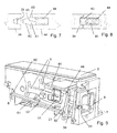
- the brewing module according to Figures 1-6 has guided in an outer housing 1 a diverter 3 and an injector 4.
- the diversion device 3 and the injector 4 are displaceable relative to one another by pivoting the operating lever 5.
- the operating lever is pivotable for this purpose about a pivot pin 6, which is present on the outer housing 1 or held by this.
- the injector 4 is displaceable by a pivoting movement of the operating lever 5 down in the direction of the discharge device 3, while the latter is immovable relative to the outer housing 1.
- the outer housing 1 can be composed as in the illustrated embodiment of two half-shells 1.1, 1.2, which is in Figures 1 and 2 sees.
- the half-shells 1.1, 1.2 may be formed on the inside so that they receive the housing-mounted parts - eg. The diverter or slidingly mounted injector positioning. So these parts may even be stored without separate fasteners (screws or the like), of course, of screws (or similar), which fasten the two half-shells together.
- the brewing module serves as a horizontal brewing module of a coffee machine, which together with the brewing module a water tank, a
- Water heating device eg, instantaneous water heater
- a pump for supplying brewing water to the injector 4 has.
- the corresponding feed channels 18 and possibly a check valve etc. of the injector can be designed as known per se; they are not the subject of the invention and will not be described in detail here.
- the injector also has at least one piercing tip 12 with associated feed opening, so that the capsule can be pierced and supplied with the extraction liquid through the feed opening.
- the coffee machine further has, for example, a capsule container arranged below the brewing chamber, into which the capsule is automatically ejected after the brewing process by lifting the operating lever.
- the diversion device 3 is provided with at least one piercing tip 11 and an associated discharge opening 19. Furthermore, depending on the configuration, there is also a discharge line with which coffee (or the like) emerging from the outlet 8 of the diversion device is guided in such a way that it runs into a cup parked at the intended location. Also leading to the exit 8 channels are not described here in detail.
- the injector 4 is constructed in the illustrated embodiment of four parts: an injector support as the first injector 41 with supply channel for bringing hot water and held on the first injector Injektorplattenhalter injectors with piercing tips 12, a capsule 43 and the capsule at least partially surrounding injetations wornem Brühhuntgepatuseteil 44th
- the discharge device is here constructed in several parts with a Ausleitvoriquessgephaseuse 31 with Ausleitkanal 19 or Ausleitkanälen 19 for the Brühgetränk and extraction-side piercing tips 11, an extraction-side capsule 33 and extraction-side Brühttinggephin 34.
- the injection-side 44 and / or the extraction-side Brühschgeophuseteil 34 can still - a groove 45 out - have a Brühhuntdichtung 81 which rests in the closed state of the brewing chamber on each other Brühmodulteil and thus seals the brewing chamber from the outside.
- the multipartite nature of the injector and / or diversion device can be advantageous in terms of production, but is not a prerequisite for the functioning of the invention.
- the respective piercing tips 11, 12 can be formed on the actual respective brewing module part 31, 41 or as in FIG WO 2010/118544 based Fig. 19-24 executed on a separate part piercing (plate) available or otherwise be designed as appropriate. Apart from the type of attachment, the piercing tips and elements to which they are attached, according to the WO 2010/118544 be executed.
- the throw-in opening is formed in the outer housing 1, is located in the region of the diversion device 3 and, like the latter, remains stationary during a movement of the operating lever.
- the throw-in opening may narrow slightly conically towards the bottom so as to have a centering effect on the capsule during insertion without the risk of tilting of the capsule being too great.
- the brewing module is designed so that the axial direction - the axis connecting the injector and discharge device, along which the movable brewing module part (ie here the injector) is moved when opening and closing the brewing chamber - easily, for example by about 5 °, opposite is inclined to the horizontal, in such a way that the movable brewing module part (ie, here the injector) moves slightly downward when it moves toward the stationary brewing module part (ie here the discharge device).
- FIG. 6 are also the axis injector-diverter 14 and the angle 15 to the horizontal 16 drawn out; the axis injector-diverting device essentially also corresponds to the capsule axis of symmetry or is parallel to it.
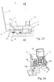
- the brewing module further comprises a support element 21. Together with a support projection 36 of the diversion device 3, this forms a support for the inserted through the insertion opening 7 capsule.
- FIG. 4 shows a detail of the brewing module in the open state with inserted capsule 10. It can also be seen that the insertion opening 7 and the discharge device 3 are positioned relative to each other so that the capsule comes to lie directly in front of the extraction-side piercing tips 11, that either already touched or is at a distance of at most the height of a peak of these.
- FIGS. 4 and 5 one also sees the extraction-side capsule seal 33 and the injector-side capsule seal 43 particularly well.
- the injector-side capsule seal 43 has a plurality of successive sealing ribs 48, which are formed on the sealing collar and surround the capsule in a sealing manner.
- the capsule seals 33, 43 according to the teaching of PCT / CH2010 / 000249 be formed, to which express reference is made here.
- FIG. 6 shows the brewing chamber in the closed state of the brewing module.
- the brewing chamber housing parts 34, 44 of the diversion device and the injector fit together accurately.
- the circulating, surrounding the capsule brewing chamber housing parts 34, 44 of the discharge device and the injector abut each other and thus close the brewing chamber. They form (in the capsule form shown here) side walls of the closed brewing chamber.
- a Brühtredichtung At the contact surface (front side) may still be present for this purpose a Brühschichtung.
- the Brühschichtung can be attached to the injector or on the diversion and pressed against a corresponding sealing surface of the other part. Often, it is preferred that the seal be secured to the injector, since in the open state it is in a retracted position and therefore better protected.
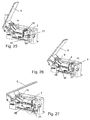
- FIGS. 7 and 8 show two examples of such a sealing principle.
- the brewing chamber seal 81 according to FIG. 7 has an axially projecting lip 82 which engages in a corresponding groove 35 of the other Brühhuntteils. In addition, it also forms a shoulder 83, which is pressed against the corresponding surface of the other Brühhuntteils.
- a rear attachment section 84 anchors the seal in the corresponding brew chamber.
- the brewing chamber seal according to FIG. 8 corresponds to the front side of the 'Quadring' principle with two sealing lips 82 which engage in a common wide groove of the other Brühhuntteils.
- Other sealing principles would be conceivable, for example, even with a single Sealing lip or a sealing bead, which is pressed against a surface, for example. In the form of an O-ring - or according to several sealing lips / sealing beads.
- FIG. 9 shows still a non-sectional view, in which one of the two half-shells of the outer housing 1, however, is not shown.
- Fig. 9 the brewing chamber is closed.
- the Kapselabstreifimplantation 51 have been folded on both sides by the approaching injector to the outside, and the support member 21 is moved downwards into the rest position.
- a retaining element 61 designed as a rod pivotable about a housing-fixed axis 62 is in engagement with the support element 21 with its extraction-side end.
- the extraction-side end of the retaining element 61 was clipped onto the corresponding part of the support element when the brewing chamber was closed by a pivoting movement of the retaining element.
- the injector When the brewing chamber is opened by pivoting the operating lever 5, the injector is displaced away from the discharge device (in FIG Fig. 9 back left). Once the leading edge of the injector is displaced behind the capsule stripping elements 51, they fold inwardly toward the capsule and clamp them against further retraction.
- the retaining member 61 prevents at the same time that the support element is pivoted back into the support position due to the action of the spring (s) holding it (not shown).
- the capsule can fall down into the capsule container as soon as the brewing chamber is sufficiently wide open. Only upon complete opening of the brewing chamber by moving the operating lever almost to a stop, the support element comes back into the support position.
- Fig. 9 clearly visible are the two connecting rods 9, which implement the pivotal movement of the operating lever 5 in the linear movement of the injector 4.
- the operation of individual parts is explained in more detail with reference to a second embodiment of the brewing module.
- the second embodiment differs from the first embodiment, first, by the not discussed here in detail deviating configuration of the outer housing.
- the mechanism of the operative connection between injector and support element is solved differently.
- the design of the support element triggering mechanism does not depend on the shape and design of the individual parts, except, of course, of the function-related features discussed here explicitly.
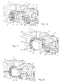
- FIG. 10 shows the attached alternative brewing module in view without capsule.
- the support element 21 which in this embodiment has an optional planar lateral guide section 22, and one of the stripping elements 51. Both the support element 21 and the stripping elements 51 are due to the action of associated springs in the in Fig. 10 illustrated position / orientation.
- FIG. 11 shows the brewing module with also shown cut, inserted through the insertion opening capsule 10. To brew the drink, the brewing chamber is closed. For this purpose, for example, likewise by actuating an operating lever, the first brewing module part is displaced relative to the second brewing module part; Here, the injector 4 is driven in the direction of the discharge device 3.
- FIG. 12 shows the brewing module during this movement.
- FIG. 13 shows as the following figures, a view of the breast module not shown cut from another side, (compared to Orientation according to Fig. 13 rotated by about 180 ° about a vertical axis) with parts of the outer housing are omitted.
- the stripping elements 51 are still in the non-pivoted starting position.
- FIG. 14 the brewing chamber is almost and in FIG. 15 completely closed.
- the scraper elements 51 which are mounted so as to be pivotable about a vertical axis, are swung back and forth against the extraction side by the approaching injector against the spring force.
- An optional over the pivot axis outwardly projecting batch serves here to attach the spring;
- the retaining element 61 is here a pivotable about a retaining element pivot pin 65 with a retention portion 64 which engages in a correspondingly shaped receiving recess 24 of the support element 21 when it is pivoted to its rest position.
- a correspondingly biased spring pivots the retaining element in this orientation.
- the stripping elements 51 When opening the brewing chamber as in FIG. 16 visible initially the support element 21 held by the retaining member 61 in the rest position, because it remains locked with this. As a result of the moving away of the injector, the stripping elements 51 can fold back inwards on account of the spring force and bear against the capsule 10 with their inside edge. As the injector continues to move away, the stripping elements 51 retain the capsule (FIG. FIG. 16 ), so that this, as soon as the injector is no longer sufficient for them, falls down into the capsule container.
- FIG. 16 illustrated variant on the combination of a quiescent at a circumferential weld of the capsule (as developed in the separation welding process, which in the WO 2010/118543 described) and frictional forces.
- the embodiment of Figures 1-6 and 9 provides that the stripping elements are dimensioned so that they are not completely folded inwards when standing on the capsule, but remain at an angle to the radial direction. So it comes (also) to a jamming, possibly in combination with a queuing at a reinforcement (weld seam, collar). In FIG. 17 you can see the queuing of the circumferential weld 10.1 on the stripping element even more clearly.
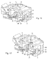
- FIG. 18 shows the brewing module with the brewing chamber completely open.
- the capsule has fallen down into the capsule container and is no longer visible.
- the moving back of the support element 21 in the support position is in the embodiment of Fig. 11-19 triggered as follows.
- a triggering pin 66 serving as the triggering part, which is fastened or formed on the injector, is guided in an elongate recess (oblong hole) 69 of a triggering element 68.
- the trigger element 68 is connected to the retaining element 61 at one extraction-side end.
- the triggering pin When the brewing chamber is fully opened, the triggering pin abuts the injector-side end of the oblong hole 69 and pulls the triggering element somewhat with it so that it tilts the retaining element 61 counter to the spring force and thus releases the latching connection with the supporting element. This pivots back into the resting position.
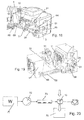
- An extraction device in particular a coffee machine with a brewing module has, as in FIG. 20 schematically illustrated, in addition to the brewing module a water tank 71, a pump 72 for supplying brewing water to the injector 4 and a water heater 73 (eg, water heater) on. Below the brewing module, a capsule container 75 is arranged, in which the capsules 10 fall or are transported after the brewing process.
- the coffee machine further has, for example, a capsule container 75 arranged below the brewing chamber, into which the capsule is automatically ejected after the brewing process by raising the operating lever 5.
- brewing modules for an extraction device, such as a coffee machine, for portionwise preparation of a beverage or other extraction product from a packed in a capsule extraction material feasible which comprises a first brewing module part and a second brewing module part movable relative thereto, the first and second brewing module parts forming a discharge device for discharging an extraction product from the capsule and an injector for introducing an extraction liquid into the capsule and a brewing chamber which encloses the capsule Brewing at least partially surrounds and by moving the second Brühmodulteils relative to the first Brühmodulteil from an open to a closed state can be brought, wherein the first and / or the second Brühmodulteil piercing tips for piercing the capsule by puncturing a capsule wall.
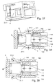
- Figures 21-24 show the brewing module or parts thereof in the opened state when inserting the capsule.
- the ejectors 101 protrude into the space formed by the injection-side seal 43 and will form the brewing chamber when closed.
- the capsule is centered and positioned by the lateral guides.
- a Ausstosser connecting rod 103 is present in addition to the connecting rods 9 for converting the operating lever 5 -Schwenkamba in an axial movement of the injector 4. This is attached to the operating lever 5 at a closer to the pivot axis (defined by the pivot pin 6) as the attachment point of the connecting rod 9 point. As a result, the ejectors 101 are also moved in a pivoting movement of the operating lever in the direction of movement of the injector, but slower and thus ultimately a shorter distance.
- Figures 25-27 show the brewing module in continuous stages of the closing process. It can be seen how a ramp-like actuating surface 46 of the injector presses the support element 21 away from the support position.
- the retaining element 68 is axially freely movable and is moved if necessary ( Fig. 27 . Fig. 29 ).
- the geometry of the arrangement is chosen so that in the closed state, the ejector 101 are completely withdrawn from the brewing chamber.
- the ejector (see in particular Fig. 22 ) on the front side a head section 105 with a slightly enlarged diameter, at the back of a - not shown in the figures - circumferential seal may be present, which is pressed against relative to the injector 4 retracted state of the ejector against a arranged in the interior of the injector shoulder and so seals.
- Fig. 28 it can be seen how, when the brewing chamber is closed, the capsule is pierced by the piercing tips 12 at least on the injection side.
- the capsule When opening the brewing chamber ( FIGS. 32 and 33 ), the capsule is first ejected from the injector-side capsule seal 43 which surrounds it by the ejectors 101 being retracted by a shorter distance than the injector and thus being displaced into the brewing chamber relative thereto.
- the ejectors are dimensioned and the ejector connecting rod 103 is arranged so that the capsule is completely detached from the injector-side capsule seal 43 and falls down before the brewing module is fully opened. Only at the end of the opening movement of the driving pin 66 of the injector will take the trigger element (bracket) 68 and retract the support element over the dead center, whereupon the spring 121 moves it back into the support position.
- the rotary damper 125 prevents an immediate snap back into the support position, which ensures that even with very rapid opening of the brewing module, the support element can not be in the resting position again, before the capsule has fallen down.
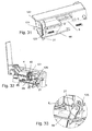
- Figures 34-39 show an embodiment of a brewing module (shown without control lever and ejection / ejection mechanism), in which the support element 21 is in two parts. It has a first support element part 21.1 and a second support element part 21.2.
- Figures 34-36 show the brewing module in the opened state of the brewing chamber in which the capsule can be inserted or inserted.
- FIG. 35 and in particular in the view according to Fig. 36 which illustrates the brewing module tilted to the side, it can be seen how the support element parts 21.1, 21.2 are formed as a bracket running laterally of the capsule with an end portion engaging under the capsule.
- FIG. 37 shows the brewing module in the closed state of the brewing chamber in which the support element is in its rest position by the two support element parts are pivoted outwardly.
- the support element parts in addition to the side of the capsule extending bracket with end part also has a substantially horizontal pivoting lever game here.
- the pivot lever parts are fixed by a housing-fixed pivot pin 141 pivotally mounted on the housing 1.
- the movement of the support element parts 21.1, 21.2 is effected by the guidance of a guide pin 142 in a gate of the second Brühmodulteils (the injector 4).
- a backdrop is present here in a mirror-image arrangement.
- the scenes include an outer guide groove 144 and an inner guide groove 146.
- the guide pin When reopening the brewing chamber ( Fig. 39 ; Injector 4 is moved back to the right) the guide pin will remain in the inner guide groove 146 until the guide pin abuts a second stop 149. As a result of the further retraction of the injector 4, the guide pin is carried along to the rear (ie towards the injector side), which causes the support element part 21.1, 21.2 to pivot inwards while the guide pin 142 slides outwards at the same time.
- the brewing module is ready again for a capsule insert, and when re-closing the guide pin is according Fig. 38 again guided in the outer guide groove 144.
- the features of the support element and the corresponding actuating mechanism described with reference to the embodiments and the characteristics of the stripping elements and the corresponding mechanism can be implemented and varied independently of each other, including embodiments with a direct connection between these elements are conceivable.
- An interaction between the support element and stripping elements is characterized in that the support element should optionally be preferably in the rest position when the stripping elements engage the capsule.
Priority Applications (1)
| Application Number | Priority Date | Filing Date | Title |
|---|---|---|---|
| EP13702321.4A EP2806773B1 (de) | 2012-01-25 | 2013-01-25 | Brühmodul |
Applications Claiming Priority (3)
| Application Number | Priority Date | Filing Date | Title |
|---|---|---|---|
| EP12405010 | 2012-01-25 | ||
| EP13702321.4A EP2806773B1 (de) | 2012-01-25 | 2013-01-25 | Brühmodul |
| PCT/CH2013/000014 WO2013110206A1 (de) | 2012-01-25 | 2013-01-25 | Brühmodul |
Publications (2)
| Publication Number | Publication Date |
|---|---|
| EP2806773A1 EP2806773A1 (de) | 2014-12-03 |
| EP2806773B1 true EP2806773B1 (de) | 2016-09-21 |
Family
ID=47632641
Family Applications (1)
| Application Number | Title | Priority Date | Filing Date |
|---|---|---|---|
| EP13702321.4A Active EP2806773B1 (de) | 2012-01-25 | 2013-01-25 | Brühmodul |
Country Status (14)
| Country | Link |
|---|---|
| US (1) | US9492028B2 (da) |
| EP (1) | EP2806773B1 (da) |
| JP (1) | JP6086929B2 (da) |
| KR (1) | KR102115045B1 (da) |
| CN (1) | CN104168804B (da) |
| BR (1) | BR112014017900B1 (da) |
| CA (1) | CA2866728C (da) |
| DK (1) | DK2806773T3 (da) |
| ES (1) | ES2608721T3 (da) |
| HU (1) | HUE031109T2 (da) |
| PL (1) | PL2806773T3 (da) |
| PT (1) | PT2806773T (da) |
| RU (1) | RU2623953C2 (da) |
| WO (1) | WO2013110206A1 (da) |
Cited By (1)
| Publication number | Priority date | Publication date | Assignee | Title |
|---|---|---|---|---|
| WO2023036484A1 (de) | 2021-09-10 | 2023-03-16 | Eugster / Frismag Ag | Brüheinheit mit optimierter haltestruktur und verfahren zum betrieb einer solchen brüheinheit |
Families Citing this family (22)
| Publication number | Priority date | Publication date | Assignee | Title |
|---|---|---|---|---|
| EP2850980A1 (de) | 2013-09-20 | 2015-03-25 | Luna Technology Systems LTS GmbH | Perforationsvorrichtung für Extraktionsgerät zum Herstellen von Brühprodukten |
| EP2856917A1 (de) * | 2013-10-01 | 2015-04-08 | Luna Technology Systems LTS GmbH | Brühmodul |
| ITRM20130593A1 (it) * | 2013-10-25 | 2015-04-26 | Io Come Ides Ltd | Macchina per erogazione di bevande |
| EP2889225A1 (de) * | 2013-12-24 | 2015-07-01 | Luna Technology Systems LTS GmbH | Portionenkapsel zum Zubereiten eines Brüherzeugnisses |
| US10045654B2 (en) | 2014-02-14 | 2018-08-14 | Coffee Solutions, Llc | Moving inlet nozzles in beverage systems |
| EP3028608A1 (de) | 2014-12-01 | 2016-06-08 | Qbo Coffee GmbH | Brühmodul, kapselerkennungsmodul und getränkezubereitungsmaschine |
| WO2017046294A1 (en) * | 2015-09-18 | 2017-03-23 | Nestec S.A. | Removal of a capsule from a capsule holder |
| US11745906B2 (en) * | 2015-11-23 | 2023-09-05 | Cupper Llc | System, apparatus, and method for preparing a beverage cartridge |
| US20220361705A1 (en) * | 2015-11-23 | 2022-11-17 | Cupper, Llc | System, apparatus and method for preparing a beverage cartridge |
| EP3175749A1 (de) * | 2015-12-01 | 2017-06-07 | Qbo Coffee GmbH | Getränkezubereitungsmaschine zum zubereiten eines getränks |
| EP3175747A1 (de) * | 2015-12-03 | 2017-06-07 | Qbo Coffee GmbH | Getränkezubereitungsmaschine |
| WO2017108759A1 (en) * | 2015-12-22 | 2017-06-29 | Koninklijke Philips N.V. | Brewing unit for a beverage producing machine and machine containing the brewing unit |
| PT109303B (pt) * | 2016-04-07 | 2021-02-15 | Novadelta Comercio Ind Cafes Sa | Dispositivo de extração com suporte de cápsula móvel |
| IT201600126287A1 (it) * | 2016-12-14 | 2018-06-14 | Caffitaly System Spa | Apparecchiatura per la preparazione di una bevanda tramite infusione di una sostanza alimentare con acqua |
| EP3338600A1 (de) * | 2016-12-22 | 2018-06-27 | Qbo Coffee GmbH | Brühmodul und getränkezubereitungsmaschine |
| EP3338601A1 (de) * | 2016-12-22 | 2018-06-27 | Qbo Coffee GmbH | Brühmodul und getränkezubereitungsmaschine |
| WO2018200186A1 (en) * | 2017-04-28 | 2018-11-01 | Contessa Christopher | Automated smoothie machine using smoothie packets |
| DE102018105213A1 (de) * | 2018-03-07 | 2019-09-12 | Melitta Single Portions Gmbh & Co. Kg | Vorrichtung und Verfahren zur Herstellung eines Brühgetränks |
| IT201800005819A1 (it) * | 2018-05-29 | 2019-11-29 | Sistema per la preparazione di bevande da capsule monouso | |
| KR20190010520A (ko) | 2018-12-12 | 2019-01-30 | 이찬호 | 음료 추출 시스템 |
| CN109588987B (zh) * | 2018-12-25 | 2023-11-28 | 深圳市西啡科技有限公司 | 饮料制备装置及饮料制备设备 |
| CN112021941B (zh) * | 2019-06-04 | 2022-04-15 | 广东美的生活电器制造有限公司 | 酿造装置和饮品机 |
Family Cites Families (45)
| Publication number | Priority date | Publication date | Assignee | Title |
|---|---|---|---|---|
| FR2723524B1 (fr) * | 1994-08-10 | 1996-10-04 | Mediterraneenne Cafes | Perfectionnements aux machines pour la preparation d'infusions de boissons chaudes |
| HU219923B (hu) | 1993-12-20 | 2001-09-28 | Compagnie Mediterraneenne Des Cafes (S.A.) | Automata gép meleg italok, mint például kávé leforrázásos elkészítésére |
| US6079315A (en) | 1999-01-19 | 2000-06-27 | Keurig, Inc. | Beverage filter cartridge holder |
| GB2397505B (en) * | 2003-01-24 | 2006-01-04 | Kraft Foods R & D Inc | System and method for the preparation of beverages |
| EP1495702A1 (fr) * | 2003-07-10 | 2005-01-12 | Nestec S.A. | Dispositif pour l'extraction d'une capsule |
| US7165488B2 (en) | 2003-12-12 | 2007-01-23 | Keurig, Incorporated | Brew chamber for a single serve beverage brewer |
| ITMI20050854A1 (it) | 2005-05-12 | 2006-11-13 | Perfect Steam Appliances Ltd | Gruppo di infusione per macchine per la preparazione di bevande |
| WO2007016977A1 (de) | 2005-08-05 | 2007-02-15 | Delica Ag | Vorrichtung zum extrahieren eines in einer kapsel enthaltenen extraktionsgutes mit einem flüssigen extraktionsmittel |
| ITLE20060009A1 (it) * | 2006-03-10 | 2006-06-09 | Giovanni Spinelli | Invenzione nel campo delle macchine da caffe' a fap/capsule |
| PT1859712E (pt) * | 2006-05-24 | 2009-02-02 | Nestec Sa | Módulo de perfuração de cápsulas |
| PT1859714E (pt) * | 2006-05-24 | 2009-03-25 | Nestec Sa | Dispositivo de infusão e sistema de infusão de cápsulas com um porta-cápsulas para facilitar introdução e remoção de cápsulas |
| ITMI20061307A1 (it) * | 2006-07-06 | 2008-01-07 | Perfect Steam Appliances Ltd | Gruppo di infusione per macchina per la preparazione di bevande |
| ITFI20060194A1 (it) | 2006-08-04 | 2008-02-05 | Saeco Ipr Ltd | Dispositivo di infusione per la preparazione di bevande da capsule monodose |
| ES2342224T3 (es) * | 2006-08-25 | 2010-07-02 | Delica Ag | Medio para penetrar un embalaje individual, el cual contiene un producto de extraccion, dispositivo de extraccion del producto de extraccion conteniendo en el embalaje individual, asi como metodo de fabricacion del medio. |
| ATE474798T1 (de) * | 2007-01-15 | 2010-08-15 | Swiss Caffe Asia Ltd | Kapsel, mittel zum penetrieren des bodens einer kapsel und vorrichtung für die zubereitung eines getränks |
| ITFI20070028A1 (it) * | 2007-02-07 | 2008-08-08 | Saeco Ipr Ltd | Dispositivo di infusione per la preparazione di bevande da capsule monodose con un dispositivo di centraggio delle capsule. |
| GB2449422B (en) * | 2007-05-18 | 2009-09-16 | Kraft Foods R & D Inc | Improvements in or relating to beverage preparation machines |
| GB2449420B (en) * | 2007-05-18 | 2009-10-21 | Kraft Foods R & D Inc | Improvments in or relating to beverage preparation machines |
| CN100544647C (zh) * | 2007-06-15 | 2009-09-30 | 宁波三A集团电器有限公司 | 咖啡机中咖啡包的自动脱落机构 |
| CN103169378B (zh) * | 2007-10-04 | 2016-09-07 | 雀巢产品技术援助有限公司 | 饮料冲煮单元 |
| PL2071987T3 (pl) * | 2007-12-18 | 2010-09-30 | Nestec Sa | Urządzenie do przyrządzania napojów zawierające regulowany mechanizm zamykający |
| PT2679120T (pt) * | 2008-03-14 | 2017-02-14 | Mocoffee Ag | Aparelho e cápsula para a preparação de uma bebida |
| EP2105074B1 (de) * | 2008-03-28 | 2011-07-20 | Delica AG | Vorrichtung und Anordnung zum Zubereiten eines flüssigen Lebens- oder Genussmittels sowie Portionsverpackung |
| EP2177136A1 (de) | 2008-10-17 | 2010-04-21 | Delica AG | Vorrichtung und Anordnung zum Zubereiten eines flüssigen Lebens- oder Genussmittels |
| IT1391885B1 (it) * | 2008-11-03 | 2012-01-27 | Hausbrandt Trieste 1892 Spa | Dispositivo perforatore per capsule e macchina per la preparazione di bevande inglobante tale dispositivo. |
| BRPI1008321A2 (pt) * | 2009-02-11 | 2019-09-24 | Ethical Coffee Company Sa | dispositivo para a preparação de uma bebida extraída a partir de uma cápsula |
| IT1393007B1 (it) * | 2009-03-12 | 2012-04-11 | Emmebielle S R L | Macchina per la preparazione mediante infusione di bevande mediante capsule |
| DK2687460T3 (da) * | 2009-04-15 | 2016-01-11 | Qbo Coffee Gmbh | Indretning til brygning af kaffe |
| WO2010118545A2 (de) | 2009-04-15 | 2010-10-21 | Luna Technology Systems Lts Gmbh | Brühmodul |
| AU2010237535B2 (en) | 2009-04-15 | 2016-10-20 | Qbo Coffee Gmbh | Device for discharging an extraction product out of a portion packaging; puncturing device and extraction apparatus |
| EP2485629B1 (en) * | 2009-10-05 | 2014-01-08 | Nestec S.A. | Ergonomic capsule extraction device |
| IT1396016B1 (it) * | 2009-10-15 | 2012-11-09 | Swiss Caffe Asia Ltd | Dispositivo di infusione per capsule da infusi e simili, particolarmente per macchine da caffe' espresso e simili. |
| ES2438840T3 (es) * | 2009-12-01 | 2014-01-20 | Nestec S.A. | Dispositivo de extracción de cartucho |
| CN101744537A (zh) * | 2009-12-18 | 2010-06-23 | 广东亿龙电器股份有限公司 | 一种胶囊萃取设备 |
| PL2368466T3 (pl) * | 2010-03-24 | 2014-06-30 | Delica Ag | Urządzenie do przyrządzania napoju |
| EP2384996A1 (de) * | 2010-05-04 | 2011-11-09 | Luna Technology Systems LTS GmbH | Kapsel für ein Extraktionsgut, Verfahren zu deren Herstellung, und Einrichtung zum Brühen von Kaffee |
| DE102010044945A1 (de) * | 2010-05-28 | 2011-12-01 | Eugster/Frismag Ag | Brühvorrichtung zum Extrahieren einer Portionskapsel, Verfahren zum Betrieb einer Brühvorrichtung, Verfahren zur Herstellung einer Brühvorrichtung und Verwendung einer Brühvorrichtung |
| DE102011011204A1 (de) * | 2010-05-28 | 2011-12-01 | Eugster/Frismag Ag | Brühvorrichtung zum Extrahieren einer Portionskapsel, Verfahren zum Betrieb einer Brühvorrichtung und Verwendung einer Brühvorrichtung |
| CN201755135U (zh) * | 2010-07-28 | 2011-03-09 | 沈高明 | 咖啡机冲泡器结构 |
| PT2624731E (pt) * | 2010-10-08 | 2015-12-07 | Qbo Coffee Gmbh | Aparelho de extração e sistema vedante |
| CN102151089B (zh) * | 2011-01-30 | 2013-04-17 | 苏州工业园区咖乐美电器有限公司 | 冲泡咖啡胶囊的咖啡机 |
| CN102188161B (zh) * | 2011-01-31 | 2013-01-16 | 苏州工业园区咖乐美电器有限公司 | 一种手动胶囊咖啡机 |
| IT1403684B1 (it) * | 2011-02-07 | 2013-10-31 | Emmebielle S R L | Macchina per la preparazione di bevande mediante infusione. |
| CN102178456B (zh) * | 2011-03-30 | 2013-03-06 | 苏州工业园区咖乐美电器有限公司 | 一种手动胶囊咖啡机 |
| CN102309255B (zh) * | 2011-09-14 | 2014-02-12 | 广东新宝电器股份有限公司 | 一种饮料淬取机构 |
-
2013
- 2013-01-25 CA CA2866728A patent/CA2866728C/en not_active Expired - Fee Related
- 2013-01-25 PT PT137023214T patent/PT2806773T/pt unknown
- 2013-01-25 BR BR112014017900-0A patent/BR112014017900B1/pt active IP Right Grant
- 2013-01-25 US US14/373,702 patent/US9492028B2/en active Active
- 2013-01-25 EP EP13702321.4A patent/EP2806773B1/de active Active
- 2013-01-25 ES ES13702321.4T patent/ES2608721T3/es active Active
- 2013-01-25 PL PL13702321T patent/PL2806773T3/pl unknown
- 2013-01-25 DK DK13702321.4T patent/DK2806773T3/da active
- 2013-01-25 JP JP2014553592A patent/JP6086929B2/ja active Active
- 2013-01-25 WO PCT/CH2013/000014 patent/WO2013110206A1/de active Application Filing
- 2013-01-25 RU RU2014133873A patent/RU2623953C2/ru active
- 2013-01-25 HU HUE13702321A patent/HUE031109T2/en unknown
- 2013-01-25 CN CN201380015487.4A patent/CN104168804B/zh active Active
- 2013-01-25 KR KR1020147023273A patent/KR102115045B1/ko active IP Right Grant
Cited By (1)
| Publication number | Priority date | Publication date | Assignee | Title |
|---|---|---|---|---|
| WO2023036484A1 (de) | 2021-09-10 | 2023-03-16 | Eugster / Frismag Ag | Brüheinheit mit optimierter haltestruktur und verfahren zum betrieb einer solchen brüheinheit |
Also Published As
| Publication number | Publication date |
|---|---|
| US9492028B2 (en) | 2016-11-15 |
| HUE031109T2 (en) | 2017-06-28 |
| DK2806773T3 (da) | 2017-01-02 |
| PL2806773T3 (pl) | 2017-02-28 |
| JP2015504745A (ja) | 2015-02-16 |
| BR112014017900A8 (pt) | 2017-07-11 |
| RU2014133873A (ru) | 2016-03-20 |
| BR112014017900A2 (pt) | 2017-06-20 |
| CA2866728A1 (en) | 2013-08-01 |
| KR102115045B1 (ko) | 2020-05-26 |
| WO2013110206A1 (de) | 2013-08-01 |
| JP6086929B2 (ja) | 2017-03-01 |
| ES2608721T3 (es) | 2017-04-12 |
| CN104168804A (zh) | 2014-11-26 |
| CN104168804B (zh) | 2017-10-03 |
| CA2866728C (en) | 2020-04-28 |
| BR112014017900B1 (pt) | 2021-08-10 |
| PT2806773T (pt) | 2016-12-29 |
| US20140348994A1 (en) | 2014-11-27 |
| KR20140116945A (ko) | 2014-10-06 |
| RU2623953C2 (ru) | 2017-06-29 |
| EP2806773A1 (de) | 2014-12-03 |
Similar Documents
| Publication | Publication Date | Title |
|---|---|---|
| EP2806773B1 (de) | Brühmodul | |
| EP2418987B1 (de) | Brühmodul | |
| EP2624731B1 (de) | Extraktionsgerät und dichtungssystem | |
| EP3051986B1 (de) | Brühmodul | |
| EP1559351B1 (de) | Brühvorrichtung für eine Kaffeemaschine | |
| EP2566784B2 (de) | Kapsel für ein extraktionsgut und getränke-zubereitungssystem | |
| EP2512302B1 (de) | Vorrichtung zum zubereiten eines getränks und kapsel | |
| EP2742832B1 (de) | Zubereitungssystem zum Zubereiten eines Brüherzeugnisses | |
| DE60107199T2 (de) | Extraktionsvorrichtung mit integrierter Kapselzuführeinrichtung | |
| EP1183975B1 (de) | Kaffeemaschine zum Aufbrühen von in einer Kapsel abgepacktem Pulverkaffee | |
| EP3052408B1 (de) | Kapsel und system zur zubereitung eines flüssigen lebensmittels | |
| WO2010118543A1 (de) | Kapsel für ein extraktionsgut, verfahren zu deren herstellung, und einrichtung zum brühen von kaffee | |
| EP1674007A1 (de) | Getränkemaschine zur Herstellung eines Heissgetränks durch Aufbrühen und Extrahieren einer in einer Kapsel abgepackten Substanz | |
| WO2012004256A1 (de) | Behälter | |
| EP3175748B1 (de) | Getränkezubereitungsvorrichtung, system sowie betriebsverfahren | |
| EP4013271A1 (de) | Getränkezubereitungsvorrichtung und verfahren zur zubereitung eines getränks mithilfe einer portionskapsel eines ersten und eines zweiten typs, sowie system umfassend eine getränkezubereitungsvorrichtung und ein portionskapselset | |
| DE202005021159U1 (de) | Brühvorrichtung für eine Kaffeemaschine | |
| WO2023036601A1 (de) | Getränkezubereitungsmaschine, sowie verfahren und system zur getränkezubereitung | |
| WO2018099983A1 (de) | Brühvorrichtung zum extrahieren einer portionskapsel, portionskapselmaschine und kapseladapter | |
| EP2989943A1 (de) | Brühvorrichtung zum Extrahieren einer Portionskapsel |
Legal Events
| Date | Code | Title | Description |
|---|---|---|---|
| PUAI | Public reference made under article 153(3) epc to a published international application that has entered the european phase |
Free format text: ORIGINAL CODE: 0009012 |
|
| 17P | Request for examination filed |
Effective date: 20140709 |
|
| AK | Designated contracting states |
Kind code of ref document: A1 Designated state(s): AL AT BE BG CH CY CZ DE DK EE ES FI FR GB GR HR HU IE IS IT LI LT LU LV MC MK MT NL NO PL PT RO RS SE SI SK SM TR |
|
| DAX | Request for extension of the european patent (deleted) | ||
| RIN1 | Information on inventor provided before grant (corrected) |
Inventor name: DEUBER, LOUIS |
|
| RAP1 | Party data changed (applicant data changed or rights of an application transferred) |
Owner name: QBO COFFEE GMBH |
|
| GRAP | Despatch of communication of intention to grant a patent |
Free format text: ORIGINAL CODE: EPIDOSNIGR1 |
|
| RIC1 | Information provided on ipc code assigned before grant |
Ipc: A47J 31/36 20060101AFI20160316BHEP Ipc: A23F 5/26 20060101ALI20160316BHEP Ipc: A47J 31/40 20060101ALI20160316BHEP |
|
| INTG | Intention to grant announced |
Effective date: 20160414 |
|
| GRAS | Grant fee paid |
Free format text: ORIGINAL CODE: EPIDOSNIGR3 |
|
| GRAA | (expected) grant |
Free format text: ORIGINAL CODE: 0009210 |
|
| AK | Designated contracting states |
Kind code of ref document: B1 Designated state(s): AL AT BE BG CH CY CZ DE DK EE ES FI FR GB GR HR HU IE IS IT LI LT LU LV MC MK MT NL NO PL PT RO RS SE SI SK SM TR |
|
| REG | Reference to a national code |
Ref country code: GB Ref legal event code: FG4D Free format text: NOT ENGLISH |
|
| REG | Reference to a national code |
Ref country code: CH Ref legal event code: EP |
|
| REG | Reference to a national code |
Ref country code: AT Ref legal event code: REF Ref document number: 830342 Country of ref document: AT Kind code of ref document: T Effective date: 20161015 |
|
| REG | Reference to a national code |
Ref country code: IE Ref legal event code: FG4D Free format text: LANGUAGE OF EP DOCUMENT: GERMAN |
|
| RIN2 | Information on inventor provided after grant (corrected) |
Inventor name: DEUBER, LOUIS |
|
| REG | Reference to a national code |
Ref country code: DE Ref legal event code: R096 Ref document number: 502013004668 Country of ref document: DE |
|
| REG | Reference to a national code |
Ref country code: RO Ref legal event code: EPE |
|
| REG | Reference to a national code |
Ref country code: CH Ref legal event code: NV Representative=s name: FREI PATENTANWALTSBUERO AG, CH |
|
| REG | Reference to a national code |
Ref country code: SE Ref legal event code: TRGR |
|
| REG | Reference to a national code |
Ref country code: PT Ref legal event code: SC4A Ref document number: 2806773 Country of ref document: PT Date of ref document: 20161229 Kind code of ref document: T Free format text: AVAILABILITY OF NATIONAL TRANSLATION Effective date: 20161221 |
|
| REG | Reference to a national code |
Ref country code: DK Ref legal event code: T3 Effective date: 20161227 |
|
| REG | Reference to a national code |
Ref country code: NL Ref legal event code: FP |
|
| REG | Reference to a national code |
Ref country code: FR Ref legal event code: PLFP Year of fee payment: 5 |
|
| REG | Reference to a national code |
Ref country code: LT Ref legal event code: MG4D |
|
| REG | Reference to a national code |
Ref country code: NO Ref legal event code: T2 Effective date: 20160921 |
|
| PG25 | Lapsed in a contracting state [announced via postgrant information from national office to epo] |
Ref country code: RS Free format text: LAPSE BECAUSE OF FAILURE TO SUBMIT A TRANSLATION OF THE DESCRIPTION OR TO PAY THE FEE WITHIN THE PRESCRIBED TIME-LIMIT Effective date: 20160921 Ref country code: HR Free format text: LAPSE BECAUSE OF FAILURE TO SUBMIT A TRANSLATION OF THE DESCRIPTION OR TO PAY THE FEE WITHIN THE PRESCRIBED TIME-LIMIT Effective date: 20160921 Ref country code: LT Free format text: LAPSE BECAUSE OF FAILURE TO SUBMIT A TRANSLATION OF THE DESCRIPTION OR TO PAY THE FEE WITHIN THE PRESCRIBED TIME-LIMIT Effective date: 20160921 |
|
| PG25 | Lapsed in a contracting state [announced via postgrant information from national office to epo] |
Ref country code: LV Free format text: LAPSE BECAUSE OF FAILURE TO SUBMIT A TRANSLATION OF THE DESCRIPTION OR TO PAY THE FEE WITHIN THE PRESCRIBED TIME-LIMIT Effective date: 20160921 Ref country code: GR Free format text: LAPSE BECAUSE OF FAILURE TO SUBMIT A TRANSLATION OF THE DESCRIPTION OR TO PAY THE FEE WITHIN THE PRESCRIBED TIME-LIMIT Effective date: 20161222 |
|
| REG | Reference to a national code |
Ref country code: ES Ref legal event code: FG2A Ref document number: 2608721 Country of ref document: ES Kind code of ref document: T3 Effective date: 20170412 |
|
| PG25 | Lapsed in a contracting state [announced via postgrant information from national office to epo] |
Ref country code: EE Free format text: LAPSE BECAUSE OF FAILURE TO SUBMIT A TRANSLATION OF THE DESCRIPTION OR TO PAY THE FEE WITHIN THE PRESCRIBED TIME-LIMIT Effective date: 20160921 |
|
| PG25 | Lapsed in a contracting state [announced via postgrant information from national office to epo] |
Ref country code: SK Free format text: LAPSE BECAUSE OF FAILURE TO SUBMIT A TRANSLATION OF THE DESCRIPTION OR TO PAY THE FEE WITHIN THE PRESCRIBED TIME-LIMIT Effective date: 20160921 Ref country code: SM Free format text: LAPSE BECAUSE OF FAILURE TO SUBMIT A TRANSLATION OF THE DESCRIPTION OR TO PAY THE FEE WITHIN THE PRESCRIBED TIME-LIMIT Effective date: 20160921 Ref country code: IS Free format text: LAPSE BECAUSE OF FAILURE TO SUBMIT A TRANSLATION OF THE DESCRIPTION OR TO PAY THE FEE WITHIN THE PRESCRIBED TIME-LIMIT Effective date: 20170121 Ref country code: BG Free format text: LAPSE BECAUSE OF FAILURE TO SUBMIT A TRANSLATION OF THE DESCRIPTION OR TO PAY THE FEE WITHIN THE PRESCRIBED TIME-LIMIT Effective date: 20161221 |
|
| REG | Reference to a national code |
Ref country code: DE Ref legal event code: R097 Ref document number: 502013004668 Country of ref document: DE |
|
| REG | Reference to a national code |
Ref country code: HU Ref legal event code: AG4A Ref document number: E031109 Country of ref document: HU |
|
| PLBE | No opposition filed within time limit |
Free format text: ORIGINAL CODE: 0009261 |
|
| STAA | Information on the status of an ep patent application or granted ep patent |
Free format text: STATUS: NO OPPOSITION FILED WITHIN TIME LIMIT |
|
| 26N | No opposition filed |
Effective date: 20170622 |
|
| PG25 | Lapsed in a contracting state [announced via postgrant information from national office to epo] |
Ref country code: MC Free format text: LAPSE BECAUSE OF FAILURE TO SUBMIT A TRANSLATION OF THE DESCRIPTION OR TO PAY THE FEE WITHIN THE PRESCRIBED TIME-LIMIT Effective date: 20160921 |
|
| PG25 | Lapsed in a contracting state [announced via postgrant information from national office to epo] |
Ref country code: SI Free format text: LAPSE BECAUSE OF FAILURE TO SUBMIT A TRANSLATION OF THE DESCRIPTION OR TO PAY THE FEE WITHIN THE PRESCRIBED TIME-LIMIT Effective date: 20160921 Ref country code: LU Free format text: LAPSE BECAUSE OF NON-PAYMENT OF DUE FEES Effective date: 20170125 |
|
| REG | Reference to a national code |
Ref country code: FR Ref legal event code: PLFP Year of fee payment: 6 |
|
| PG25 | Lapsed in a contracting state [announced via postgrant information from national office to epo] |
Ref country code: MT Free format text: LAPSE BECAUSE OF FAILURE TO SUBMIT A TRANSLATION OF THE DESCRIPTION OR TO PAY THE FEE WITHIN THE PRESCRIBED TIME-LIMIT Effective date: 20160921 |
|
| PG25 | Lapsed in a contracting state [announced via postgrant information from national office to epo] |
Ref country code: AL Free format text: LAPSE BECAUSE OF FAILURE TO SUBMIT A TRANSLATION OF THE DESCRIPTION OR TO PAY THE FEE WITHIN THE PRESCRIBED TIME-LIMIT Effective date: 20160921 |
|
| REG | Reference to a national code |
Ref country code: CH Ref legal event code: PCAR Free format text: NEW ADDRESS: POSTFACH, 8032 ZUERICH (CH) |
|
| PG25 | Lapsed in a contracting state [announced via postgrant information from national office to epo] |
Ref country code: CY Free format text: LAPSE BECAUSE OF FAILURE TO SUBMIT A TRANSLATION OF THE DESCRIPTION OR TO PAY THE FEE WITHIN THE PRESCRIBED TIME-LIMIT Effective date: 20160921 |
|
| PG25 | Lapsed in a contracting state [announced via postgrant information from national office to epo] |
Ref country code: MK Free format text: LAPSE BECAUSE OF FAILURE TO SUBMIT A TRANSLATION OF THE DESCRIPTION OR TO PAY THE FEE WITHIN THE PRESCRIBED TIME-LIMIT Effective date: 20160921 |
|
| PGFP | Annual fee paid to national office [announced via postgrant information from national office to epo] |
Ref country code: RO Payment date: 20230119 Year of fee payment: 11 Ref country code: NO Payment date: 20230123 Year of fee payment: 11 Ref country code: IE Payment date: 20230119 Year of fee payment: 11 Ref country code: FR Payment date: 20230124 Year of fee payment: 11 Ref country code: FI Payment date: 20230120 Year of fee payment: 11 Ref country code: DK Payment date: 20230123 Year of fee payment: 11 Ref country code: CZ Payment date: 20230117 Year of fee payment: 11 Ref country code: CH Payment date: 20230106 Year of fee payment: 11 Ref country code: AT Payment date: 20230120 Year of fee payment: 11 |
|
| PGFP | Annual fee paid to national office [announced via postgrant information from national office to epo] |
Ref country code: TR Payment date: 20230123 Year of fee payment: 11 Ref country code: SE Payment date: 20230119 Year of fee payment: 11 Ref country code: IT Payment date: 20230120 Year of fee payment: 11 Ref country code: BE Payment date: 20230119 Year of fee payment: 11 |
|
| P01 | Opt-out of the competence of the unified patent court (upc) registered |
Effective date: 20230529 |
|
| PGFP | Annual fee paid to national office [announced via postgrant information from national office to epo] |
Ref country code: ES Payment date: 20230405 Year of fee payment: 11 |
|
| PGFP | Annual fee paid to national office [announced via postgrant information from national office to epo] |
Ref country code: PT Payment date: 20231221 Year of fee payment: 12 |
|
| PGFP | Annual fee paid to national office [announced via postgrant information from national office to epo] |
Ref country code: PL Payment date: 20231221 Year of fee payment: 12 Ref country code: NL Payment date: 20240119 Year of fee payment: 12 |
|
| PGFP | Annual fee paid to national office [announced via postgrant information from national office to epo] |
Ref country code: ES Payment date: 20240223 Year of fee payment: 12 Ref country code: IE Payment date: 20240119 Year of fee payment: 12 |
|
| PGFP | Annual fee paid to national office [announced via postgrant information from national office to epo] |
Ref country code: AT Payment date: 20240122 Year of fee payment: 12 |
|
| PGFP | Annual fee paid to national office [announced via postgrant information from national office to epo] |
Ref country code: RO Payment date: 20240111 Year of fee payment: 12 Ref country code: HU Payment date: 20240123 Year of fee payment: 12 Ref country code: FI Payment date: 20240119 Year of fee payment: 12 Ref country code: DE Payment date: 20240119 Year of fee payment: 12 Ref country code: CZ Payment date: 20240115 Year of fee payment: 12 Ref country code: GB Payment date: 20240123 Year of fee payment: 12 Ref country code: CH Payment date: 20240202 Year of fee payment: 12 |