EP2806719B1 - Montagekopf-haltevorrichtung für eine komponentenmontagemaschine - Google Patents
Montagekopf-haltevorrichtung für eine komponentenmontagemaschine Download PDFInfo
- Publication number
- EP2806719B1 EP2806719B1 EP12866384.6A EP12866384A EP2806719B1 EP 2806719 B1 EP2806719 B1 EP 2806719B1 EP 12866384 A EP12866384 A EP 12866384A EP 2806719 B1 EP2806719 B1 EP 2806719B1
- Authority
- EP
- European Patent Office
- Prior art keywords
- holding section
- head
- head holding
- engaging member
- mounting head
- Prior art date
- Legal status (The legal status is an assumption and is not a legal conclusion. Google has not performed a legal analysis and makes no representation as to the accuracy of the status listed.)
- Active
Links
Images






Classifications
-
- H—ELECTRICITY
- H05—ELECTRIC TECHNIQUES NOT OTHERWISE PROVIDED FOR
- H05K—PRINTED CIRCUITS; CASINGS OR CONSTRUCTIONAL DETAILS OF ELECTRIC APPARATUS; MANUFACTURE OF ASSEMBLAGES OF ELECTRICAL COMPONENTS
- H05K13/00—Apparatus or processes specially adapted for manufacturing or adjusting assemblages of electric components
- H05K13/04—Mounting of components, e.g. of leadless components
- H05K13/0404—Pick-and-place heads or apparatus, e.g. with jaws
-
- Y—GENERAL TAGGING OF NEW TECHNOLOGICAL DEVELOPMENTS; GENERAL TAGGING OF CROSS-SECTIONAL TECHNOLOGIES SPANNING OVER SEVERAL SECTIONS OF THE IPC; TECHNICAL SUBJECTS COVERED BY FORMER USPC CROSS-REFERENCE ART COLLECTIONS [XRACs] AND DIGESTS
- Y10—TECHNICAL SUBJECTS COVERED BY FORMER USPC
- Y10T—TECHNICAL SUBJECTS COVERED BY FORMER US CLASSIFICATION
- Y10T403/00—Joints and connections
- Y10T403/60—Biased catch or latch
- Y10T403/602—Biased catch or latch by separate spring
-
- Y—GENERAL TAGGING OF NEW TECHNOLOGICAL DEVELOPMENTS; GENERAL TAGGING OF CROSS-SECTIONAL TECHNOLOGIES SPANNING OVER SEVERAL SECTIONS OF THE IPC; TECHNICAL SUBJECTS COVERED BY FORMER USPC CROSS-REFERENCE ART COLLECTIONS [XRACs] AND DIGESTS
- Y10—TECHNICAL SUBJECTS COVERED BY FORMER USPC
- Y10T—TECHNICAL SUBJECTS COVERED BY FORMER US CLASSIFICATION
- Y10T403/00—Joints and connections
- Y10T403/70—Interfitted members
-
- Y—GENERAL TAGGING OF NEW TECHNOLOGICAL DEVELOPMENTS; GENERAL TAGGING OF CROSS-SECTIONAL TECHNOLOGIES SPANNING OVER SEVERAL SECTIONS OF THE IPC; TECHNICAL SUBJECTS COVERED BY FORMER USPC CROSS-REFERENCE ART COLLECTIONS [XRACs] AND DIGESTS
- Y10—TECHNICAL SUBJECTS COVERED BY FORMER USPC
- Y10T—TECHNICAL SUBJECTS COVERED BY FORMER US CLASSIFICATION
- Y10T403/00—Joints and connections
- Y10T403/70—Interfitted members
- Y10T403/7005—Lugged member, rotary engagement
- Y10T403/7007—Bayonet joint
Definitions
- the present invention relates to a component mounter mounting head holding device which detachably holds a mounting head for mounting components on a circuit board to a head holding section of a component mounter.
- the component mounter given in patent literature 1 (Japanese Patent Publication Number 4546857 ) comprises a mounting head holding multiple suction nozzles, wherein the mounting head is attached and held to a head holding section of a component mounter using negative air pressure in order to be capable of being automatically exchanged according to circumstances such as the type, shape, and size of components.
- a system according to the preamble of independent claim 1 is disclosed in patent literature 2 (Japanese Patent Application Publication Number H03-82197 ).
- the object of the present invention is a component mounter mounting head holding device which prevents a mounting head that is detachably held to a head holding section of a component mounter from deviating positionally or falling off.
- An embodiment of the present disclosure is a component mounter mounting head holding device for detachably holding a mounting head which mounts components to a circuit board to a head holding section of a component mounter, comprising: a member to be engaged provided on the connecting section for the head holding section of the mounting head; an engaging member provided on the head holding section which moves between an engagement position for holding the mounting head in which the engaging member is engaged with the member to be engaged and a release position in which the engaging member is separated from the member to be engaged; and an air cylinder provided on the head holding section which is the power source for moving the engaging member between the engagement position and the release position.
- the holding power of the mounting head can be increased more than conventional negative pressure attachment power, and it is possible to prevent a mounting head which is detachably held to the head holding section from deviating positionally or falling off.
- the engaging member of the head holding section in an L-shape or J-shape which holds the member to be engaged of the mounting head by hooking it from underneath.
- the engaging member may be provided on the head holding section so that it is capable of being moved up and down with the uppermost position and lowermost position of that movement stroke being the engagement position and release position respectively.
- the head holding section of a component mounter is generally configured to be capable of being rotated around its center axis (Z axis) by a rotating mechanism, if that rotating mechanism is used, the respective positions of the head holding section and the mounting head can be shifted and the mounting head can be attached/detached to/from the head holding section.
- the configuration may be such that the engaging member is provided on the head holding section so that it is capable of being rotated around a rotating axis, with one direction position of that rotation stroke and another direction position thereof being the engagement position and release position respectively.
- the engaging member of the head holding section is held in a state rotated to the release position, it is possible for the engaging member of the head holding section to pass by the side of the member to be engaged of the mounting head, and the mounting head can be attached/detached.
- an elastic member for biasing the engaging member in the engagement position direction on the head holding section.
- the mounting head which is detachably held to a head holding section may be a rotary head with multiple suction nozzles for picking up components arranged in a circumferential direction at predetermined intervals, a mounting head with only one large suction nozzle attached, or a mounting head with a chuck for grabbing components attached.
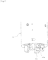
- FIG. 1 This describes embodiment 1 of the present invention based on FIG. 1 to FIG. 6 .
- Multiple (for example, four) engaging members 13 for detachably engaging and holding mounting head 12 are provided movably in the up/down direction on head holding section 11 of the component mounter.
- head holding section 11 is configured such that, as well as being capable of being moved in the XYZ directions by an XYZ moving mechanism, is capable of being rotated around the center axis (Z axis) of said head holding section 11 by a rotating mechanism.
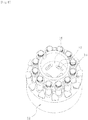
- Mounting head 12 is a rotary head with multiple suction nozzles (not shown in figures) for picking up components arranged in a circumferential direction at predetermined intervals.
- Multiple engaging members 13 are formed respectively as L-shapes or J-shapes and are arranged at even intervals in a circumferential direction with the center axis (Z axis) of head holding section 11 as the center, and the direction of claw section 13a of each engaging member 13 is arranged so as to be facing in the same direction as the normal rotational direction (or the reverse rotational direction) of head holding section 11.
- multiple elongated holes 16 are formed at even intervals in a circumferential direction on connecting section 15 for the head holding section 11 of mounting head 12 in order for each engaging member 13 of head holding section 11 to pass through, and pin to be engaged 17 which is a member to be engaged that is engaged by claw section 13a of engaging member 13 is fixedly penetrating on one side of each elongated hole 16 in the radial direction of mounting head 12.
- pin to be engaged 17 of each elongated hole 16 To the side of pin to be engaged 17 of each elongated hole 16, a gap is maintained so that engaging member 13 can pass by in the up/down direction.
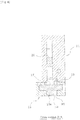
- air cylinders 18 for moving each engaging member 13 respectively in the up/down direction are provided close to each engaging member 13 of head holding section 11.
- Engaging member 13 is connected via arm 20 to piston 19 of each air cylinder 18, piston 19 is moved up/down and engaging member 13 moves in the up/down direction, and the uppermost position and lowermost position of that movement stroke are the engagement position and release position respectively.
- Spring 21 (elastic member) such as a compression coil spring for biasing piston 19 in the up direction which is the engagement position direction is provided below piston 19 of each air cylinder 18. Further, it is acceptable to provide the elastic member such as a spring for biasing engaging member 13 in the engagement position direction close to engaging member 13.
- the space above and the space below piston 19 of each air cylinder 18 are respectively configured such that it is possible to switch between a state connected to a compressed air supply system for supplying compressed air and a state connected to an exhaust system for exhausting air.
- piston 19 If compressed air is supplied to the space below piston 19 of air cylinder 18 with the space above piston 19 in a state connected to an exhaust system, as shown in FIG. 3 and FIG. 4 , piston 19 is pushed up by the pressure of the compressed air and the elastic force of spring 21 such that engaging member 13 rises to the engagement position. And, if compressed air is supplied to the space above piston 19 with the space below piston 19 in a state connected to an exhaust system, as shown in FIG.5 and FIG. 6 , piston 19 is pushed down against the elastic force of spring 21 by the pressure of the compressed air such that engaging member 13 lowers to the release position.
- the configuration may be such that negative pressure (vacuum pressure) is supplied instead of compressed air to the space above and the space below piston 19 of each air cylinder 18, in which case it is acceptable to supply negative pressure to the space above piston 19 when raising engaging member 13 to the engagement position and to supply negative pressure to the space below piston 19 when lowering engaging member 13 to the release position.
- negative pressure vacuum pressure
- claw 13a of engaging member 13 is made to be in a position below pin to be engaged 17. After this, as shown in FIG. 3 and FIG. 4 , claw section 13a of engaging member 13 is engaged with pin 17 to be engaged by raising piston 19 of air cylinder 18 and raising engaging member 13 to the engagement position. By this, mounting head 12 becomes attached to head holding section 11.
- the holding power of mounting head 12 can be increased more than conventional negative pressure attachment power, and it is possible to prevent mounting head 12 which is detachably held to head holding section 11 from deviating positionally or falling off even when electricity is not being supplied.
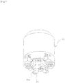
- the configuration was such that multiple engaging members 13 were provided on head holding section 11 capable of being moved up and down, but with embodiment 2 shown in FIG. 7 to FIG. 11 , multiple engaging members 31 are provided on head holding section 11 capable of being rotated in a perpendicular direction to pin to be engaged 17 via rotational axis 32, with one direction (the pin to be engaged 17 side) position and another direction position of that rotation stroke being the engagement position and release position respectively.
- Each engaging member 31 is formed as a whole in a roughly chevron shape, with the bend section thereof penetrated by rotational axis 32, with the lower section of engaging member 31 formed in an L-shape or J-shape, the tip of which is claw section 31a for engaging with pin to be engaged 17, and with the upper section of engaging member 31 extending above air cylinder 18, in the tip of which is formed elongated hole 33, with this elongated hole 33 engaged in a freely sliding manner with fixed pin 34 which is fixed to piston 19 of air cylinder 18.
- engaging member 31 is rotated between the engagement position and the release position by moving piston 19 of air cylinder 18 up/down.
- Spring 35 such as a torsion coil spring which is an elastic member for biasing engaging member 31 in the direction of the engagement position is provided on head holding section 11 close to each engaging member 31. Further, it is acceptable to provide the elastic member such as a spring for biasing engaging member 31 in the engagement position direction inside air cylinder 18.
- mounting head 12 which is detachably held to head holding section 11 is not limited to being a rotary head, and may be a mounting head with only one large suction nozzle attached, or a mounting head with a chuck for grabbing components attached.
- the present invention may be embodied with various changes that do not extend beyond the scope of the invention, such as changing the quantity of engaging members and members to be engaged, or changing the form of the engaging members and members to be engaged.
Landscapes
- Engineering & Computer Science (AREA)
- Manufacturing & Machinery (AREA)
- Microelectronics & Electronic Packaging (AREA)
- Supply And Installment Of Electrical Components (AREA)
- General Engineering & Computer Science (AREA)
- Mechanical Engineering (AREA)
Claims (5)
- System, bei dem ein Teilabschnitt (11) zum Halten eines Kopfes einer Bauteil-Montagevorrichtung einen Montage-Kopf (12), der Bauteile an einer Leiterplatte montiert, abnehmbar hält, wobei es umfasst:den Teilabschnitt (11) zum Halten des Kopfes;den Montage-Kopf (12);ein passives Eingriffselement (17), das sich an einem Verbindungs-Teilabschnitt (15) des Montage-Kopfes (12) befindet und zum Verbinden mit dem Teilabschnitt (11) zum Halten eines Kopfes eingerichtet ist;ein aktives Eingriffselement (13, 31), das in einer L- Form oder einer J- Form ausgebildet ist, sich an dem Teilabschnitt (11) zum Halten eines Kopfes befindet und so eingerichtet ist, dass es sich zwischen einer Eingriffs-Position zum Halten des Montage-Kopfes (12), in der das aktive Eingriffselement (13, 31) in Eingriff mit den passiven Eingriffselement ist, und einer Löse-Position bewegt, in der das aktive Eingriffselement (13, 31) von dem passiven Eingriffselement (17) getrennt ist; sowieeinen Druckluftzylinder (18), der sich an dem Teilabschnitt (11) zum Halten eines Kopfes befindet und die Kraftquelle ist, die zum Bewegen des aktiven Eingriffselementes (13, 31) zwischen der Eingriffs-Position und der Löse-Position eingerichtet ist;dadurch gekennzeichnet, dassdas aktive Eingriffselement (13, 31) so eingerichtet ist, dass es von unten einhakt, um das passive Eingriffselement (17) zu halten.
- System nach Anspruch 1, dadurch gekennzeichnet, dass es des Weiteren umfasst:einen Mechanismus zum Bewegen auf einer Z-Achse, der zum Absenken und Anheben des Teilabschnitts (11) zum Halten eines Kopfes eingerichtet ist; sowieeinen Dreh-Mechanismus, der zum Drehen des Teilabschnitts (11) zum Halten eines Kopfes um die Z-Achse herum eingerichtet ist;wobei das aktive Eingriffselement (13) so beschaffen ist, dass es nach oben und nach unten bewegt werden kann, und die Konstruktion so ist, dass die oberste Position und die unterste Position des Hubs dieser Bewegung die Eingriffs-Position bzw. die Löse-Position sind;wobei, um den Montage-Kopf (12) an dem Teilabschnitt (11) zum Halten eines Kopfes anzubringen:der Druckluftzylinder (18) so eingerichtet ist, dass er das aktive Eingriffselement (13) an die Löse-Position bewegt,der Dreh-Mechanismus so eingerichtet ist, dass er dann den Teilabschnitt (11) zum Halten eines Kopfes an eine Position dreht, an der das aktive Eingriffselement (13) die Seite des passiven Eingriffselementes (17) passieren kann,der Mechanismus zum Bewegen auf einer Z-Achse so eingerichtet ist, dass er dann den Teilabschnitt (11) zum Halten eines Kopfes so absenkt, dass er dem Montage-Kopf (12) gegenüberliegt, der Dreh-Mechanismus so eingerichtet ist, dass er dann den Teilabschnitt (11) zum Halten eines Kopfes so dreht, dass der untere Teilabschnitt des aktiven Eingriffselementes (13) sich unterhalb des passiven Eingriffselementes (17) befindet,der Druckluftzylinder (18) so eingerichtet ist, dass er das aktive Eingriffselement (13) dann an die Eingriffs-Position bewegt und so den Montage-Kopf (12) an dem Teilabschnitt (11) zum Halten eines Kopfes anbringt; undwobei, um den Montage-Kopf (12) von dem Teilabschnitt (11) zum Halten eines Kopfes zu lösen:der Druckluftzylinder (18) so eingerichtet ist, dass er das aktive Eingriffselement (13) an die Löse-Position bewegt,der Dreh-Mechanismus so eingerichtet ist, dass er dann den Teilabschnitt (11) zum Halten eines Kopfes an eine Position dreht, an der das aktive Eingriffselement (13) die Seite des passiven Eingriffselementes (17) passieren kann, undder Mechanismus zum Bewegen auf einer Z-Achse so eingerichtet ist, dass er dann den Teilabschnitt (11) zum Halten eines Kopfes anhebt und so den Montage-Kopf (12) von dem Teilabschnitt (11) zum Halten eines Kopfes löst.
- System nach Anspruch 1, dadurch gekennzeichnet, dass es des Weiteren einen Mechanismus zum Bewegen auf einer Z-Achse umfasst, der zum Absenken und Anheben des Teilabschnitts (11) zum Halten eines Kopfes eingerichtet ist;
wobei das aktive Eingriffselement (31) so beschaffen ist, dass es um eine Drehachse (32) herum gedreht werden kann, und die Konstruktion so ist, dass die eine Position in einer Richtung dieses Dreh-Hubs und die Position in einer anderen Richtung desselben die Eingriffs-Position bzw. die Löse-Position sind;
wobei, um den Montage-Kopf (12) an dem Teilabschnitt (11) zum Halten eines Kopfes anzubringen:der Druckluftzylinder (18) so eingerichtet ist, dass er das aktive Eingriffselement (31) an die Löse-Position dreht,der Mechanismus zum Bewegen auf einer Z-Achse so eingerichtet ist, dass er dann den Teilabschnitt (11) zum Halten eines Kopfes so absenkt, dass er dem Montage-Kopf (12) gegenüberliegt, undder Druckluftzylinder (18) so eingerichtet ist, dass er das aktive Eingriffselement (31) dann an die Eingriffs-Position dreht und so den Montage-Kopf (12) an dem Teilabschnitt (11) zum Halten eines Kopfes anbringt; undwobei, um den Montage-Kopf (12) von dem Teilabschnitt (11) zum Halten eines Kopfes zu lösen:der Druckluftzylinder (18) so eingerichtet ist, dass er das aktive Eingriffselement (31) an die Löse-Position dreht,der Mechanismus zum Bewegen auf einer Z-Achse so eingerichtet ist, dass er dann den Teilabschnitt (11) zum Halten eines Kopfes anhebt und so den Montage-Kopf (12) von dem Teilabschnitt (11) zum Halten eines Kopfes löst. - System nach einem der Ansprüche 1 bis 3, dadurch gekennzeichnet, dass ein elastisches Element (21), das so eingerichtet ist, dass es das aktive Eingriffselement (13, 31) an die Eingriffs-Position spannt, an dem Teilabschnitt (11) zum Halten eines Kopfes vorhanden ist.
- System nach einem der Ansprüche 1 bis 4, dadurch gekennzeichnet, dass der Montage-Kopf (12) ein Dreh-Kopf mit mehreren Saugdüsen ist, die in einer Umfangsrichtung in vorgegebenen Abständen angeordnet sind und zum Aufnehmen von Bauteilen eingerichtet sind.
Applications Claiming Priority (1)
| Application Number | Priority Date | Filing Date | Title |
|---|---|---|---|
| PCT/JP2012/051203 WO2013108394A1 (ja) | 2012-01-20 | 2012-01-20 | 部品実装機の装着ヘッド保持装置 |
Publications (3)
| Publication Number | Publication Date |
|---|---|
| EP2806719A1 EP2806719A1 (de) | 2014-11-26 |
| EP2806719A4 EP2806719A4 (de) | 2015-07-01 |
| EP2806719B1 true EP2806719B1 (de) | 2019-03-13 |
Family
ID=48798840
Family Applications (1)
| Application Number | Title | Priority Date | Filing Date |
|---|---|---|---|
| EP12866384.6A Active EP2806719B1 (de) | 2012-01-20 | 2012-01-20 | Montagekopf-haltevorrichtung für eine komponentenmontagemaschine |
Country Status (5)
| Country | Link |
|---|---|
| US (1) | US9677588B2 (de) |
| EP (1) | EP2806719B1 (de) |
| JP (1) | JP5808063B2 (de) |
| CN (1) | CN104081888B (de) |
| WO (1) | WO2013108394A1 (de) |
Families Citing this family (7)
| Publication number | Priority date | Publication date | Assignee | Title |
|---|---|---|---|---|
| JP6246212B2 (ja) * | 2013-08-08 | 2017-12-13 | 富士機械製造株式会社 | 部品実装機 |
| EP3051935B1 (de) * | 2013-09-25 | 2018-08-22 | Fuji Machine Mfg. Co., Ltd. | Komponentenmontagevorrichtung |
| JP6438043B2 (ja) * | 2014-10-31 | 2018-12-12 | 株式会社Fuji | 部品実装機及びそれに用いるノズルツール |
| JP6378054B2 (ja) * | 2014-11-12 | 2018-08-22 | 株式会社Fuji | 部品実装機のツール保持装置および部品実装機のノズルツール |
| JP6762528B2 (ja) * | 2016-04-28 | 2020-09-30 | 株式会社Fuji | 部品実装機及びそれに用いるノズルツール |
| JP7121143B2 (ja) * | 2018-12-28 | 2022-08-17 | 株式会社Fuji | 作業ヘッド、および作業機 |
| JP7300606B2 (ja) * | 2019-10-25 | 2023-06-30 | 株式会社Fuji | 部品実装機 |
Family Cites Families (8)
| Publication number | Priority date | Publication date | Assignee | Title |
|---|---|---|---|---|
| US4664588A (en) * | 1984-03-09 | 1987-05-12 | Applied Robotics Inc. | Apparatus and method for connecting and exchanging remote manipulable elements to a central control source |
| DE3433311A1 (de) * | 1984-09-11 | 1986-03-20 | C. & E. Fein Gmbh & Co, 7000 Stuttgart | Werkzeugwechselvorrichtung fuer industrieroboter |
| JPS63123683A (ja) * | 1986-11-10 | 1988-05-27 | 三菱電機株式会社 | 部品吸着搬送装置 |
| JP2792931B2 (ja) * | 1989-08-25 | 1998-09-03 | 三洋電機株式会社 | 電子部品装着装置 |
| JPH0748384Y2 (ja) * | 1990-07-11 | 1995-11-08 | 株式会社安川電機 | ロボット用工具交換装置 |
| KR930006593B1 (ko) * | 1990-10-20 | 1993-07-21 | 현대 전자 산업 주식회사 | 반도체 리드 프레임 로우더용 헤드 유니트 |
| JP4391290B2 (ja) * | 2004-03-30 | 2009-12-24 | パナソニック株式会社 | ロータリー型部品実装装置 |
| JP4546857B2 (ja) | 2005-03-16 | 2010-09-22 | 富士機械製造株式会社 | 電子部品保持装置および電子部品装着システム |
-
2012
- 2012-01-20 US US14/372,326 patent/US9677588B2/en not_active Expired - Fee Related
- 2012-01-20 JP JP2013554160A patent/JP5808063B2/ja active Active
- 2012-01-20 CN CN201280067533.0A patent/CN104081888B/zh not_active Expired - Fee Related
- 2012-01-20 WO PCT/JP2012/051203 patent/WO2013108394A1/ja not_active Ceased
- 2012-01-20 EP EP12866384.6A patent/EP2806719B1/de active Active
Non-Patent Citations (1)
| Title |
|---|
| None * |
Also Published As
| Publication number | Publication date |
|---|---|
| WO2013108394A1 (ja) | 2013-07-25 |
| EP2806719A1 (de) | 2014-11-26 |
| US20140328617A1 (en) | 2014-11-06 |
| JPWO2013108394A1 (ja) | 2015-05-11 |
| EP2806719A4 (de) | 2015-07-01 |
| CN104081888B (zh) | 2016-10-12 |
| US9677588B2 (en) | 2017-06-13 |
| CN104081888A (zh) | 2014-10-01 |
| JP5808063B2 (ja) | 2015-11-10 |
Similar Documents
| Publication | Publication Date | Title |
|---|---|---|
| US9677588B2 (en) | Component mounter mounting head holding device | |
| EP2892312B1 (de) | Maschine zur montage von komponenten | |
| EP3026996B1 (de) | Komponentenmontagemaschine | |
| CN212824928U (zh) | 一种载具更换设备 | |
| CN101547590B (zh) | 贴装设备及贴装方法 | |
| EP3264878B1 (de) | Komponentenmontagemaschine | |
| JP2009218463A (ja) | ノズル回収装置、ノズル回収装置を備えた実装装置および回収ノズルのメンテナンス方法 | |
| CN211894904U (zh) | 一种上下料旋转机械手 | |
| KR20130051866A (ko) | 캐필러리 자동 교체시스템 | |
| WO2012014467A1 (ja) | 部品実装装置および部品実装方法 | |
| JP2014128841A (ja) | 多関節型双腕ロボットによるベルト組付けシステム | |
| CN217433553U (zh) | 汽车变速箱主从动链轮总成自动装配吸盘式夹爪 | |
| CN203682597U (zh) | 一种用于取放汽车制动盘和轮毂的自动取放装置 | |
| CN211422553U (zh) | 一种钻机 | |
| JP6246212B2 (ja) | 部品実装機 | |
| CN201634240U (zh) | 一种标准箱拆垛夹具 | |
| JP3254260U (ja) | グリッパ交換装置 | |
| CN115383524B (zh) | 一种pcb钻头生产用钻头固定装置 | |
| CN106914597A (zh) | 永磁式嵌件抓手装置 | |
| JP5109924B2 (ja) | 電子部品実装装置 | |
| CN206643320U (zh) | 永磁式嵌件抓手装置 | |
| JP5997631B2 (ja) | タイヤビード取外し装置 | |
| CN111590554A (zh) | 机械臂 | |
| CN209736955U (zh) | 拾取机构及拾取系统 | |
| KR20240167998A (ko) | 콜릿 및 돔 교체 장치 |
Legal Events
| Date | Code | Title | Description |
|---|---|---|---|
| PUAI | Public reference made under article 153(3) epc to a published international application that has entered the european phase |
Free format text: ORIGINAL CODE: 0009012 |
|
| 17P | Request for examination filed |
Effective date: 20140527 |
|
| AK | Designated contracting states |
Kind code of ref document: A1 Designated state(s): AL AT BE BG CH CY CZ DE DK EE ES FI FR GB GR HR HU IE IS IT LI LT LU LV MC MK MT NL NO PL PT RO RS SE SI SK SM TR |
|
| DAX | Request for extension of the european patent (deleted) | ||
| RA4 | Supplementary search report drawn up and despatched (corrected) |
Effective date: 20150603 |
|
| RIC1 | Information provided on ipc code assigned before grant |
Ipc: H05K 13/04 20060101AFI20150528BHEP |
|
| STAA | Information on the status of an ep patent application or granted ep patent |
Free format text: STATUS: EXAMINATION IS IN PROGRESS |
|
| 17Q | First examination report despatched |
Effective date: 20180607 |
|
| RAP1 | Party data changed (applicant data changed or rights of an application transferred) |
Owner name: FUJI CORPORATION |
|
| GRAP | Despatch of communication of intention to grant a patent |
Free format text: ORIGINAL CODE: EPIDOSNIGR1 |
|
| STAA | Information on the status of an ep patent application or granted ep patent |
Free format text: STATUS: GRANT OF PATENT IS INTENDED |
|
| INTG | Intention to grant announced |
Effective date: 20181115 |
|
| GRAS | Grant fee paid |
Free format text: ORIGINAL CODE: EPIDOSNIGR3 |
|
| RIN1 | Information on inventor provided before grant (corrected) |
Inventor name: NISHIYAMA, SATORU |
|
| GRAA | (expected) grant |
Free format text: ORIGINAL CODE: 0009210 |
|
| STAA | Information on the status of an ep patent application or granted ep patent |
Free format text: STATUS: THE PATENT HAS BEEN GRANTED |
|
| AK | Designated contracting states |
Kind code of ref document: B1 Designated state(s): AL AT BE BG CH CY CZ DE DK EE ES FI FR GB GR HR HU IE IS IT LI LT LU LV MC MK MT NL NO PL PT RO RS SE SI SK SM TR |
|
| REG | Reference to a national code |
Ref country code: GB Ref legal event code: FG4D |
|
| REG | Reference to a national code |
Ref country code: CH Ref legal event code: EP Ref country code: AT Ref legal event code: REF Ref document number: 1109500 Country of ref document: AT Kind code of ref document: T Effective date: 20190315 |
|
| REG | Reference to a national code |
Ref country code: IE Ref legal event code: FG4D |
|
| REG | Reference to a national code |
Ref country code: DE Ref legal event code: R096 Ref document number: 602012057899 Country of ref document: DE |
|
| REG | Reference to a national code |
Ref country code: NL Ref legal event code: MP Effective date: 20190313 |
|
| REG | Reference to a national code |
Ref country code: LT Ref legal event code: MG4D |
|
| PG25 | Lapsed in a contracting state [announced via postgrant information from national office to epo] |
Ref country code: LT Free format text: LAPSE BECAUSE OF FAILURE TO SUBMIT A TRANSLATION OF THE DESCRIPTION OR TO PAY THE FEE WITHIN THE PRESCRIBED TIME-LIMIT Effective date: 20190313 Ref country code: SE Free format text: LAPSE BECAUSE OF FAILURE TO SUBMIT A TRANSLATION OF THE DESCRIPTION OR TO PAY THE FEE WITHIN THE PRESCRIBED TIME-LIMIT Effective date: 20190313 Ref country code: NO Free format text: LAPSE BECAUSE OF FAILURE TO SUBMIT A TRANSLATION OF THE DESCRIPTION OR TO PAY THE FEE WITHIN THE PRESCRIBED TIME-LIMIT Effective date: 20190613 Ref country code: FI Free format text: LAPSE BECAUSE OF FAILURE TO SUBMIT A TRANSLATION OF THE DESCRIPTION OR TO PAY THE FEE WITHIN THE PRESCRIBED TIME-LIMIT Effective date: 20190313 |
|
| PG25 | Lapsed in a contracting state [announced via postgrant information from national office to epo] |
Ref country code: RS Free format text: LAPSE BECAUSE OF FAILURE TO SUBMIT A TRANSLATION OF THE DESCRIPTION OR TO PAY THE FEE WITHIN THE PRESCRIBED TIME-LIMIT Effective date: 20190313 Ref country code: NL Free format text: LAPSE BECAUSE OF FAILURE TO SUBMIT A TRANSLATION OF THE DESCRIPTION OR TO PAY THE FEE WITHIN THE PRESCRIBED TIME-LIMIT Effective date: 20190313 Ref country code: BG Free format text: LAPSE BECAUSE OF FAILURE TO SUBMIT A TRANSLATION OF THE DESCRIPTION OR TO PAY THE FEE WITHIN THE PRESCRIBED TIME-LIMIT Effective date: 20190613 Ref country code: LV Free format text: LAPSE BECAUSE OF FAILURE TO SUBMIT A TRANSLATION OF THE DESCRIPTION OR TO PAY THE FEE WITHIN THE PRESCRIBED TIME-LIMIT Effective date: 20190313 Ref country code: GR Free format text: LAPSE BECAUSE OF FAILURE TO SUBMIT A TRANSLATION OF THE DESCRIPTION OR TO PAY THE FEE WITHIN THE PRESCRIBED TIME-LIMIT Effective date: 20190614 Ref country code: HR Free format text: LAPSE BECAUSE OF FAILURE TO SUBMIT A TRANSLATION OF THE DESCRIPTION OR TO PAY THE FEE WITHIN THE PRESCRIBED TIME-LIMIT Effective date: 20190313 |
|
| REG | Reference to a national code |
Ref country code: AT Ref legal event code: MK05 Ref document number: 1109500 Country of ref document: AT Kind code of ref document: T Effective date: 20190313 |
|
| PG25 | Lapsed in a contracting state [announced via postgrant information from national office to epo] |
Ref country code: EE Free format text: LAPSE BECAUSE OF FAILURE TO SUBMIT A TRANSLATION OF THE DESCRIPTION OR TO PAY THE FEE WITHIN THE PRESCRIBED TIME-LIMIT Effective date: 20190313 Ref country code: IT Free format text: LAPSE BECAUSE OF FAILURE TO SUBMIT A TRANSLATION OF THE DESCRIPTION OR TO PAY THE FEE WITHIN THE PRESCRIBED TIME-LIMIT Effective date: 20190313 Ref country code: SK Free format text: LAPSE BECAUSE OF FAILURE TO SUBMIT A TRANSLATION OF THE DESCRIPTION OR TO PAY THE FEE WITHIN THE PRESCRIBED TIME-LIMIT Effective date: 20190313 Ref country code: PT Free format text: LAPSE BECAUSE OF FAILURE TO SUBMIT A TRANSLATION OF THE DESCRIPTION OR TO PAY THE FEE WITHIN THE PRESCRIBED TIME-LIMIT Effective date: 20190713 Ref country code: AL Free format text: LAPSE BECAUSE OF FAILURE TO SUBMIT A TRANSLATION OF THE DESCRIPTION OR TO PAY THE FEE WITHIN THE PRESCRIBED TIME-LIMIT Effective date: 20190313 Ref country code: ES Free format text: LAPSE BECAUSE OF FAILURE TO SUBMIT A TRANSLATION OF THE DESCRIPTION OR TO PAY THE FEE WITHIN THE PRESCRIBED TIME-LIMIT Effective date: 20190313 Ref country code: CZ Free format text: LAPSE BECAUSE OF FAILURE TO SUBMIT A TRANSLATION OF THE DESCRIPTION OR TO PAY THE FEE WITHIN THE PRESCRIBED TIME-LIMIT Effective date: 20190313 Ref country code: RO Free format text: LAPSE BECAUSE OF FAILURE TO SUBMIT A TRANSLATION OF THE DESCRIPTION OR TO PAY THE FEE WITHIN THE PRESCRIBED TIME-LIMIT Effective date: 20190313 |
|
| PG25 | Lapsed in a contracting state [announced via postgrant information from national office to epo] |
Ref country code: SM Free format text: LAPSE BECAUSE OF FAILURE TO SUBMIT A TRANSLATION OF THE DESCRIPTION OR TO PAY THE FEE WITHIN THE PRESCRIBED TIME-LIMIT Effective date: 20190313 Ref country code: PL Free format text: LAPSE BECAUSE OF FAILURE TO SUBMIT A TRANSLATION OF THE DESCRIPTION OR TO PAY THE FEE WITHIN THE PRESCRIBED TIME-LIMIT Effective date: 20190313 |
|
| REG | Reference to a national code |
Ref country code: DE Ref legal event code: R097 Ref document number: 602012057899 Country of ref document: DE |
|
| PG25 | Lapsed in a contracting state [announced via postgrant information from national office to epo] |
Ref country code: AT Free format text: LAPSE BECAUSE OF FAILURE TO SUBMIT A TRANSLATION OF THE DESCRIPTION OR TO PAY THE FEE WITHIN THE PRESCRIBED TIME-LIMIT Effective date: 20190313 Ref country code: IS Free format text: LAPSE BECAUSE OF FAILURE TO SUBMIT A TRANSLATION OF THE DESCRIPTION OR TO PAY THE FEE WITHIN THE PRESCRIBED TIME-LIMIT Effective date: 20190713 |
|
| PLBE | No opposition filed within time limit |
Free format text: ORIGINAL CODE: 0009261 |
|
| STAA | Information on the status of an ep patent application or granted ep patent |
Free format text: STATUS: NO OPPOSITION FILED WITHIN TIME LIMIT |
|
| PG25 | Lapsed in a contracting state [announced via postgrant information from national office to epo] |
Ref country code: DK Free format text: LAPSE BECAUSE OF FAILURE TO SUBMIT A TRANSLATION OF THE DESCRIPTION OR TO PAY THE FEE WITHIN THE PRESCRIBED TIME-LIMIT Effective date: 20190313 |
|
| 26N | No opposition filed |
Effective date: 20191216 |
|
| PG25 | Lapsed in a contracting state [announced via postgrant information from national office to epo] |
Ref country code: SI Free format text: LAPSE BECAUSE OF FAILURE TO SUBMIT A TRANSLATION OF THE DESCRIPTION OR TO PAY THE FEE WITHIN THE PRESCRIBED TIME-LIMIT Effective date: 20190313 |
|
| PG25 | Lapsed in a contracting state [announced via postgrant information from national office to epo] |
Ref country code: TR Free format text: LAPSE BECAUSE OF FAILURE TO SUBMIT A TRANSLATION OF THE DESCRIPTION OR TO PAY THE FEE WITHIN THE PRESCRIBED TIME-LIMIT Effective date: 20190313 |
|
| PG25 | Lapsed in a contracting state [announced via postgrant information from national office to epo] |
Ref country code: MC Free format text: LAPSE BECAUSE OF FAILURE TO SUBMIT A TRANSLATION OF THE DESCRIPTION OR TO PAY THE FEE WITHIN THE PRESCRIBED TIME-LIMIT Effective date: 20190313 |
|
| REG | Reference to a national code |
Ref country code: CH Ref legal event code: PL |
|
| GBPC | Gb: european patent ceased through non-payment of renewal fee |
Effective date: 20200120 |
|
| REG | Reference to a national code |
Ref country code: BE Ref legal event code: MM Effective date: 20200131 |
|
| PG25 | Lapsed in a contracting state [announced via postgrant information from national office to epo] |
Ref country code: FR Free format text: LAPSE BECAUSE OF NON-PAYMENT OF DUE FEES Effective date: 20200131 Ref country code: GB Free format text: LAPSE BECAUSE OF NON-PAYMENT OF DUE FEES Effective date: 20200120 Ref country code: LU Free format text: LAPSE BECAUSE OF NON-PAYMENT OF DUE FEES Effective date: 20200120 |
|
| PG25 | Lapsed in a contracting state [announced via postgrant information from national office to epo] |
Ref country code: CH Free format text: LAPSE BECAUSE OF NON-PAYMENT OF DUE FEES Effective date: 20200131 Ref country code: LI Free format text: LAPSE BECAUSE OF NON-PAYMENT OF DUE FEES Effective date: 20200131 Ref country code: BE Free format text: LAPSE BECAUSE OF NON-PAYMENT OF DUE FEES Effective date: 20200131 |
|
| PG25 | Lapsed in a contracting state [announced via postgrant information from national office to epo] |
Ref country code: IE Free format text: LAPSE BECAUSE OF NON-PAYMENT OF DUE FEES Effective date: 20200120 |
|
| PG25 | Lapsed in a contracting state [announced via postgrant information from national office to epo] |
Ref country code: MT Free format text: LAPSE BECAUSE OF FAILURE TO SUBMIT A TRANSLATION OF THE DESCRIPTION OR TO PAY THE FEE WITHIN THE PRESCRIBED TIME-LIMIT Effective date: 20190313 Ref country code: CY Free format text: LAPSE BECAUSE OF FAILURE TO SUBMIT A TRANSLATION OF THE DESCRIPTION OR TO PAY THE FEE WITHIN THE PRESCRIBED TIME-LIMIT Effective date: 20190313 |
|
| PG25 | Lapsed in a contracting state [announced via postgrant information from national office to epo] |
Ref country code: MK Free format text: LAPSE BECAUSE OF FAILURE TO SUBMIT A TRANSLATION OF THE DESCRIPTION OR TO PAY THE FEE WITHIN THE PRESCRIBED TIME-LIMIT Effective date: 20190313 |
|
| P01 | Opt-out of the competence of the unified patent court (upc) registered |
Effective date: 20230328 |
|
| PGFP | Annual fee paid to national office [announced via postgrant information from national office to epo] |
Ref country code: DE Payment date: 20231128 Year of fee payment: 13 |
|
| REG | Reference to a national code |
Ref country code: DE Ref legal event code: R119 Ref document number: 602012057899 Country of ref document: DE |
|
| PG25 | Lapsed in a contracting state [announced via postgrant information from national office to epo] |
Ref country code: DE Free format text: LAPSE BECAUSE OF NON-PAYMENT OF DUE FEES Effective date: 20250801 |