EP2806508B1 - Federsteckverbinder mit wasserdichtungsfunktion - Google Patents
Federsteckverbinder mit wasserdichtungsfunktion Download PDFInfo
- Publication number
- EP2806508B1 EP2806508B1 EP12866367.1A EP12866367A EP2806508B1 EP 2806508 B1 EP2806508 B1 EP 2806508B1 EP 12866367 A EP12866367 A EP 12866367A EP 2806508 B1 EP2806508 B1 EP 2806508B1
- Authority
- EP
- European Patent Office
- Prior art keywords
- conductive tube
- conductive
- hole
- distal end
- spring connector
- Prior art date
- Legal status (The legal status is an assumption and is not a legal conclusion. Google has not performed a legal analysis and makes no representation as to the accuracy of the status listed.)
- Active
Links
Images


Classifications
-
- H—ELECTRICITY
- H01—ELECTRIC ELEMENTS
- H01R—ELECTRICALLY-CONDUCTIVE CONNECTIONS; STRUCTURAL ASSOCIATIONS OF A PLURALITY OF MUTUALLY-INSULATED ELECTRICAL CONNECTING ELEMENTS; COUPLING DEVICES; CURRENT COLLECTORS
- H01R13/00—Details of coupling devices of the kinds covered by groups H01R12/70 or H01R24/00 - H01R33/00
- H01R13/46—Bases; Cases
- H01R13/52—Dustproof, splashproof, drip-proof, waterproof, or flameproof cases
- H01R13/5219—Sealing means between coupling parts, e.g. interfacial seal
-
- H—ELECTRICITY
- H01—ELECTRIC ELEMENTS
- H01R—ELECTRICALLY-CONDUCTIVE CONNECTIONS; STRUCTURAL ASSOCIATIONS OF A PLURALITY OF MUTUALLY-INSULATED ELECTRICAL CONNECTING ELEMENTS; COUPLING DEVICES; CURRENT COLLECTORS
- H01R13/00—Details of coupling devices of the kinds covered by groups H01R12/70 or H01R24/00 - H01R33/00
- H01R13/02—Contact members
- H01R13/15—Pins, blades or sockets having separate spring member for producing or increasing contact pressure
- H01R13/17—Pins, blades or sockets having separate spring member for producing or increasing contact pressure with spring member on the pin
-
- H—ELECTRICITY
- H01—ELECTRIC ELEMENTS
- H01R—ELECTRICALLY-CONDUCTIVE CONNECTIONS; STRUCTURAL ASSOCIATIONS OF A PLURALITY OF MUTUALLY-INSULATED ELECTRICAL CONNECTING ELEMENTS; COUPLING DEVICES; CURRENT COLLECTORS
- H01R13/00—Details of coupling devices of the kinds covered by groups H01R12/70 or H01R24/00 - H01R33/00
- H01R13/02—Contact members
- H01R13/22—Contacts for co-operating by abutting
- H01R13/24—Contacts for co-operating by abutting resilient; resiliently-mounted
- H01R13/2407—Contacts for co-operating by abutting resilient; resiliently-mounted characterized by the resilient means
- H01R13/2421—Contacts for co-operating by abutting resilient; resiliently-mounted characterized by the resilient means using coil springs
-
- H—ELECTRICITY
- H01—ELECTRIC ELEMENTS
- H01R—ELECTRICALLY-CONDUCTIVE CONNECTIONS; STRUCTURAL ASSOCIATIONS OF A PLURALITY OF MUTUALLY-INSULATED ELECTRICAL CONNECTING ELEMENTS; COUPLING DEVICES; CURRENT COLLECTORS
- H01R13/00—Details of coupling devices of the kinds covered by groups H01R12/70 or H01R24/00 - H01R33/00
- H01R13/46—Bases; Cases
- H01R13/52—Dustproof, splashproof, drip-proof, waterproof, or flameproof cases
- H01R13/521—Sealing between contact members and housing, e.g. sealing insert
-
- H—ELECTRICITY
- H01—ELECTRIC ELEMENTS
- H01R—ELECTRICALLY-CONDUCTIVE CONNECTIONS; STRUCTURAL ASSOCIATIONS OF A PLURALITY OF MUTUALLY-INSULATED ELECTRICAL CONNECTING ELEMENTS; COUPLING DEVICES; CURRENT COLLECTORS
- H01R13/00—Details of coupling devices of the kinds covered by groups H01R12/70 or H01R24/00 - H01R33/00
- H01R13/46—Bases; Cases
- H01R13/52—Dustproof, splashproof, drip-proof, waterproof, or flameproof cases
- H01R13/5224—Dustproof, splashproof, drip-proof, waterproof, or flameproof cases for medical use
-
- H—ELECTRICITY
- H01—ELECTRIC ELEMENTS
- H01R—ELECTRICALLY-CONDUCTIVE CONNECTIONS; STRUCTURAL ASSOCIATIONS OF A PLURALITY OF MUTUALLY-INSULATED ELECTRICAL CONNECTING ELEMENTS; COUPLING DEVICES; CURRENT COLLECTORS
- H01R4/00—Electrically-conductive connections between two or more conductive members in direct contact, i.e. touching one another; Means for effecting or maintaining such contact; Electrically-conductive connections having two or more spaced connecting locations for conductors and using contact members penetrating insulation
- H01R4/28—Clamped connections, spring connections
- H01R4/48—Clamped connections, spring connections utilising a spring, clip, or other resilient member
-
- H—ELECTRICITY
- H01—ELECTRIC ELEMENTS
- H01R—ELECTRICALLY-CONDUCTIVE CONNECTIONS; STRUCTURAL ASSOCIATIONS OF A PLURALITY OF MUTUALLY-INSULATED ELECTRICAL CONNECTING ELEMENTS; COUPLING DEVICES; CURRENT COLLECTORS
- H01R12/00—Structural associations of a plurality of mutually-insulated electrical connecting elements, specially adapted for printed circuits, e.g. printed circuit boards [PCB], flat or ribbon cables, or like generally planar structures, e.g. terminal strips, terminal blocks; Coupling devices specially adapted for printed circuits, flat or ribbon cables, or like generally planar structures; Terminals specially adapted for contact with, or insertion into, printed circuits, flat or ribbon cables, or like generally planar structures
- H01R12/70—Coupling devices
- H01R12/71—Coupling devices for rigid printing circuits or like structures
- H01R12/712—Coupling devices for rigid printing circuits or like structures co-operating with the surface of the printed circuit or with a coupling device exclusively provided on the surface of the printed circuit
- H01R12/714—Coupling devices for rigid printing circuits or like structures co-operating with the surface of the printed circuit or with a coupling device exclusively provided on the surface of the printed circuit with contacts abutting directly the printed circuit; Button contacts therefore provided on the printed circuit
Definitions
- the present invention relates to a spring connector with waterproofing function which is used for electrical connection, and has a structure for preventing intrusion of water drops.
- Patent Document 1 discloses a drip-proofing connector for electrically connecting a circuit board of a pulmonic dosing appliance and a cartridge to each other.
- This drip-proofing connector “includes a hollow body pin 11 which is press-fitted into a mounting hole 2 in a housing 1 to be engaged and fixed there, a movable pin 12 which is reciprocally inserted into this body pin 11, and a coil spring 17 which is interposed between an inner bottom face of the body pin 11 and a bottom face of the movable pin 12" (paragraph [0020] in Patent Document 1), and has such a structure that a drip-proofing cover 20 (silicone rubber or the like) is tightly fitted to an engaging groove 16 on a side face of the movable pin 12 (paragraph [0027] in
- Patent Document 1 1)
- Patent Document 1 JP-A-2007-173073
- US 2011/0159750 A1 relates to an electrical device with a contact assembly comprising at least one electrical contact having a contacting end for contacting a counterpart contact of another electrical device, and a holding device for holding the electrical contact, wherein the holding device comprises an elastomeric material in which the electrical contact is elastically held.
- the invention has been made in view of the above described circumstances, and an object of the invention is to provide a spring connector with waterproofing function which is capable of making more reliable contact as compared with the prior art. According to the invention, the object is solved by the features of claim 1.
- the sub-claims contain further preferred developments of the invention.
- a spring connector with waterproofing function comprising:
- the spring connector with waterproofing function comprises a housing having a hole for supporting at least a part of the side face of the conductive tube at a side close to the base end than the elastic member, and the distal end of the conductive pin may protrude from the hole in the housing, in a state where the distal end of the conductive pin is not in contact with the object.
- the side face of the conductive tube and an inner face of the hole of the housing are respectively provided with convex parts, and by engaging the convex parts with each other, a maximal value of a protruding amount of the distal end of the conductive tube may be restricted.
- the convex part of the conductive tube has a taper part which is reduced in diameter in a taper shape toward the base end side, and the conductive tube can be inserted into the hole of the housing from the base end side.
- the hole of the housing has a small diameter hole part and a large diameter hole part which are continued in order from the base end side of the conductive tube, the conductive tube has a small diameter part which is positioned or extended inside the small diameter hole part, and a large diameter part which is positioned or extended inside the large diameter hole part, and when the distal end of the conductive pin is pushed in so as not to protrude from the hole, a part of the large diameter part of the conductive tube may remain in the large diameter hole part.
- the spring connector with waterproofing function further includes a cover having a hole for exposing the distal end of the conductive tube, and covered over the housing from the distal end side of the conductive tube, wherein the distal end of the conductive tube can protrude from the hole of the cover, in a state where the distal end of the conductive tube is not in contact with the object, and wherein the elastic member may be clamped and pressed between the housing and the cover from both sides of an axial direction of the conductive tube.
- the conductive tube has a concave groove which encircles the side face of the conductive tube, and the elastic member may be fitted into the concave groove in elastic contact with the concave groove.
- the elastic member may be in elastic contact with a bottom face and both side faces of the concave groove at an entire circumference of the concave groove.
- a non-elastic ring which surrounds an outside of the hole of the elastic member may be integrally provided with the elastic member or be fitted into the elastic member.
- a side face of the conductive pin at the base end side may be pressed against an inner face of the conductive tube.
- the elastic member is provided on the conductive tube, while an elastic member for waterproofing is not provided on the conductive pin. For this reason, tilting movement of the conductive pin is not hindered by the elastic member, and the conductive pin can be pressed against the inner face of the conductive tube with a sufficient side pressure. As the results, it is possible to realize the spring connector with waterproofing function which is capable of making more reliable contact as compared with the prior art.
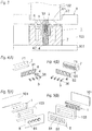
- Embodiment 1 is shown in Figs. 1 to 5(B) .
- Fig. 1 is a sectional view of a spring connector 1 with waterproofing function in an unused state, according to Embodiment 1 of the invention.
- Fig. 2 is a sectional view of the spring connector 1 with waterproofing function in a state connected at one side.
- Fig. 3 is a sectional view of the spring connector 1 with waterproofing function in a state connected at both sides (a state in use).
- Figs. 4(A) and 4(B) are exploded perspective views of the spring connector 1 with waterproofing function, as seen from opposite directions to each other. It is to be noted that a cover 8 is omitted in the drawings.
- Figs. 1 is a sectional view of a spring connector 1 with waterproofing function in an unused state, according to Embodiment 1 of the invention.
- Fig. 2 is a sectional view of the spring connector 1 with waterproofing function in a state connected at one side.
- 5(A) and 5(B) are exploded perspective views of a part of a device to which the spring connector 1 with waterproofing function is applied, as seen from opposite directions to each other.
- the cover 8 is shown in a state separated from the spring connector 1 with waterproofing function.
- the spring connector 1 with waterproofing function includes a conductive tube 3, a conductive pin 4, an insulating elastic member 6, a housing 7, and a cover 8.
- the conductive tube 3 is a conductive metallic body formed of copper alloy or the like, and to be connected to a battery 102, which is an example of an object to be connected at one side (See Fig. 3 ) .
- the conductive pin 4 is a conductive metallic body formed of copper alloy or the like, and to be connected to a circuit board 101 of an object to be connected at the other side (a medical appliance such as an instillator, which is not shown) (See Figs. 2 and 3 ). It is to be noted that in Figs. 2 and 3 , electrodes and conductive patterns of the circuit board 101 and the battery 102 are not shown.
- the conductive tube 3 has a small diameter part 31, a large diameter part 32, and a contact part 33 in order from a base end side thereof.
- a base end of the small diameter part 31 is opened and formed as a calked part 34.
- a convex part 35 is formed on a side face of the small diameter part 31.
- the convex part 35 encircles the side face of the small diameter part 31 at an intermediate position in an axial direction thereof.
- a concave groove 36 is formed on a side face of the large diameter part 32.
- the concave groove 36 encircles the side face of the large diameter part 32 at an intermediate position in an axial direction thereof.
- a hollow part 37 extending from an opening at the base end of the small diameter part 31 to the intermediate position in the axial direction of the large diameter part 32 forms an internal space in the conductive tube 3.
- a distal end of the contact part 33 is formed as a convex face such as a spherical face, and come into contact with the electrode of the battery 102, when the spring connector is used (See Fig. 3 ) .
- the conductive pin 4 has a large diameter part 41 and a small diameter part 42 in order from a base end side thereof.
- the large diameter part 41 has a larger diameter than a diameter of an opening in the caulked part 34 of the conductive tube 3, and can slide in the hollow part 37 of the conductive tube 3.
- a base end face of the large diameter part 41 is formed as an inclined face 43 which is inclined with respect to a plane perpendicular to an axial direction.
- the small diameter part 42 has a smaller diameter than the diameter of the opening in the caulked part 34 of the conductive tube 3, and protrudes from the caulked part 34.
- a distal end of the small diameter part 42 is formed as a convex face such as a spherical face, and come into contact with the electrode of the circuit board 101, when the spring connector is used (See Figs. 2 and 3 ).
- the elastic member 6 is formed of rubber such as silicone rubber, and has a hole 61 through which the conductive tube 3 is inserted to come into tight contact with a side face of the conductive tube 3.
- the elastic member 6 is fitted into the concave groove 36 of the conductive tube 3 to come into elastic contact therewith, and spread in a flange-like shape from the side face of the conductive tube 3.
- a diameter of the hole 61 of the elastic member 6 is smaller than a diameter of a bottom face of the concave groove 36 of the conductive tube 3, and a thickness of the elastic member 6 in vicinity of the hole 61 is larger than a groove width of the concave groove 36.
- an inner face of the hole 61 is in elastic contact with the bottom face of the concave groove 36 of the conductive tube 3, at an entire circumference of the concave groove 36 of the conductive tube 3, and both faces of the elastic member 6 in vicinity of the hole 61 are respectively in elastic contact with both side faces of the concave groove 36 of the conductive tube 3.
- the conductive tube 3 is fixed to the hole 61 of the elastic member 6 in tight contact thereby to prevent intrusion of water drops from the distal end side.
- the elastic member 6 has ring-like convex parts 62 which are partly enlarged in thickness, on both faces thereof, at a position separated from the side face of the conductive tube 3 by a predetermined distance.
- the housing 7 is formed of insulating resin, for example, and has a hole 71 for slidably supporting the side face of the conductive tube 3 at a side closer to the base end than the elastic member 6.
- the hole 71 has a small diameter hole part 72, a large diameter hole part 73, and an open part 74 adjacent to the elastic member, which are continued in order from the base end side of the conductive tube 3.
- the small diameter part 31 of the conductive tube 3 is passed through the small diameter hole part 72, and the large diameter part 32 of the conductive tube 3 is passed through the large diameter hole part 73.
- an edge at the base end side of the large diameter part 32 of the conductive tube 3 is chamfered, thus enabling the large diameter part 32 to be easily inserted into the large diameter hole part 73.
- the open part 74 adjacent to the elastic member is formed so as to have a larger diameter than the large diameter hole part 73, by a predetermined depth, so that deformation of the elastic member 6 along with sliding movement of the conductive tube 3 in the axial direction may not be hindered.
- the distal end of the conductive pin 4 protrudes from the hole 71 in the housing 7.
- the small diameter hole part 72 is provided with a convex part 75 on its inner face.
- the convex part 75 encircles an inner face of the small diameter hole part 72 in vicinity of an end of the small diameter hole part 72 adjacent to the large diameter hole part 73.
- the cover 8 is formed of insulating resin, for example, and covered over the housing 7 from the distal end side of the conductive tube 3, having a hole 81 for exposing the distal end of the conductive tube 3.
- the distal end of the conductive tube 3 protrudes from the hole 81 in the cover 8.
- the convex parts 62 of the elastic member 6 are clamped and pressed between the housing 7 and the cover 8 from both sides in the axial direction of the conductive tube 3. In this manner, intrusion of water drops from gaps between the housing 7 and the cover 8 is prevented.
- a case 103 (formed of insulating resin, for example) in a frame-like shape is fixed to the circuit board 101 which is the object to be connected, and the spring connector 1 with waterproofing function is inserted into the case 103.
- the cover 8 is covered over the housing 7, by being fixed to the case 103.
- a waterproofing structure is also provided between the cover 8 and the case 103, although not shown in the drawings.
- the conductive pin 4 When the spring connector 1 with waterproofing function is inserted into the case 103, the distal end of the conductive pin 4 comes into contact with the circuit board 101. On this occasion, the conductive tube 3 is urged by the spring 5 to slide along the hole 71 in the housing 7, until the convex part 35 of the small diameter part 31 is caught by (engaged with) the convex part 75 of the small diameter hole part 72 in the housing 7. Thereafter, the conductive pin 4 slides to retreat in the hollow part 37 in the conductive tube 3, resisting an urging force of the spring 5 (while pressing and contracting the spring 5).
- a protruding amount of the distal end of the conductive tube 3 is controlled at a constant value, and at the same time, a contact pressure of the distal end of the conductive pin 4 with respect to the electrode of the circuit board 101 is sufficiently secured.
- a base end side of the large diameter part 32 of the conductive tube 3 remains inside the large diameter hole part 73 in the housing7. For this reason, when the distal end of the conductive tube 3 is pushed in, thereafter, as shown in Fig. 3 , the large diameter part 32 of the conductive tube 3 is prevented from interfering with an upper end of the large diameter hole part 73 in the housing 7.
- the conductive pin 4 is tilted, and a side face of the large diameter part 41 at the base end side of the conductive pin 4 is pressed against an inner face of the hole part 37 in the conductive tube 3. As the results, the conductive tube 3 is reliably brought into contact with the conductive pin 4 to be electrically continued.
- the spring connector 1 with waterproofing function is mounted on the circuit board 101, as shown in Fig. 2 , and then, the battery 102 is mounted on the conductive tube 3 from the distal end side, as shown in Fig. 3 .
- the cover 8 is formed with a recess 82 having a shape corresponding to a shape of the battery 102. The battery 102 is inserted along the recess 82, until it comes into contact with a bottom face of the recess 82.
- the conductive tube 3 protruding from the hole 81 in the cover 8 retreats resisting the urging force of the spring 5 (while contracting the spring 5), until the distal end of the conductive tube 3 is contacted and pressed with the electrode of the battery 102 thereby to come into alignment with an open end of the hole 81 (the bottom face of the recess 82). In this manner, electrical continuity between the circuit board 101 and the battery 102 is established.
- the conductive tube 3 further retreats, the large diameter part 32 of the conductive tube 3 is butted against a step part between the large diameter hole part 73 and the small diameter hole part 72 in the housing 7, and thus, the further retreat of the conductive tube 3 is hindered. Therefore, it is possible to prevent damage of the caulked part 34 of the conductive tube 3 when it comes into contact with the circuit board 101.
- the spring 5 and the large diameter part 41 of the conductive pin 4 are inserted into the hollow part 37 in the conductive tube 3, and the base end of the conductive tube 3 is caulked to form the caulked part 34, thereby to integrate these three members in a form of an assembly.
- a plurality of these assemblies are prepared.
- the holes 61 in the elastic members 6 are fitted to the concave grooves 36 in the respective conductive tubes 3, and they are inserted in the holes 71 in the housing 7 (See Figs. 4(A) and 4(B) ).
- the convex parts 35 relatively easily override the convex parts 75 of the small diameter hole parts 72 from the above to the below in the drawings, but cannot easily override from the below to the above in the drawings (in short, the conductive tubes 3 are not withdrawn from the holes 71 in the housing 7).
- the spring connector 1 with waterproofing function In order to mount the spring connector 1 with waterproof ing function on the circuit board 101, after the case 103 is fixed to the circuit board 101, the spring connector 1 with waterproofing function (except the cover 8) is inserted into the case 103, and then, the cover 8 is fixed to the case 103 (See Figs. 5(A) and 5(B) ).
- the elastic member 6 is attached to the conductive tube 3, an elastic member for waterproofing is not attached to the conductive pin 4. Therefore, the conductive pin 4 can be freely tilted, as compared with a case where the drip-proofing cover hinders the tilting movement of the movable pin, like the drip-proofing connector as described in Patent Document 1. For this reason, the conductive pin 4 which is pushed by the spring 5 is easily tilted as compared with the movable pin in Patent Document 1, and the side face of the large diameter part 41 can be brought into contact with the inner face of the hollow part 37 in the conductive tube 3 with sufficient side pressure. Accordingly, more reliable contact can be obtained, as compared with the drip-proofing connector in Patent Document 1, and the spring connector 1 with waterproofing function which is excellent in conductivity and low resistance is realized.
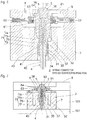
- 10 (A) and 10 (B) are exploded perspective views of a part of a device to which the spring connector 2 with waterproofing function is applied, as seen from opposite directions to each other.
- the cover 8 is shown in a state separated from the spring connector 2 with waterproofing function.
- the elastic member 6 has a thick wall part around the hole 61, and a ring-like groove 64 is formed in this thick wall part.
- a non-elastic ring 63 formed of metal, for example, which surrounds the hole 61 is fitted into the ring-like groove 64 in the elastic member 6.
- the non-elastic ring 63 has a function of enhancing rigidity of the elastic member 6 in vicinity of the hole 61. It is to be noted that the non-elastic ring 63 maybe integrally formed with the elastic member 6 by insert molding, for example.
- the elastic member 6 is provided with the non-elastic ring 63, a depth of the concave groove 36 of the conductive tube 3 is made remarkably shallow, as compared with Embodiment 1, and a main function of the concave groove 36 is to prevent displacement of the elastic member 6.
- a main function of the concave groove 36 is to prevent displacement of the elastic member 6.
- the rigidity is increased by the non-elastic ring 63, sufficient waterproofing function is obtained only by the elastic contact between the inner face of the hole 61 in the elastic member 6 and the side face of the large diameter part 32 of the conductive tube 3.
- a flange part 38 is formed at the distal end of the large diameter part 32 of the conductive tube 3 for the purpose of preventing withdrawal of the elastic member 6.
- Other features in this embodiment are substantially the same as those in Embodiment 1. According to this embodiment, in the same manner as Embodiment 1, the spring connector 2 with waterproofing function which is capable of making more reliable contact, as compared with the drip-proofing connector in
Landscapes
- Connector Housings Or Holding Contact Members (AREA)
Claims (10)
- Zugfederanschluss mit Wasserschutzfunktion, umfassend:- ein leitendes Rohr (3) mit einem distalen Ende, das ein Kontaktteil ist, um mit einem Gegenstand an einer Seite kontaktiert zu werden;- einen leitenden Stift (4) mit einem distalen Ende, das ein Kontaktteil ist, um mit einem Gegenstand an der anderen Seite kontaktiert zu werden, und von einer Öffnung an einem Basisende des leitenden Rohrs (3) hervorsteht, mit einem Basisende des leitenden Stifts (4), der im leitenden Rohr (3) enthalten ist und bezüglich des leitenden Rohrs gleiten kann, mit einer Feder (5), die innerhalb des leitenden Rohrs (3) gehalten wird, und den leitenden Stift (4) drückt, um den leitenden Stift vorzuspannen, um so vom leitenden Rohr (3) hervorzustehen; und- ein elastisches Element (6) mit einer Öffnung, in die das leitende Rohr eingesetzt wird, um in engem Kontakt mit einer Seitenfläche des leitenden Rohrs (3) gebracht zu werden, wobei das elastische Element (6) flanschartig von der Seitenfläche des leitenden Rohrs (3) aus verbreitet wird,- gekennzeichnet durch- einen Teil einer Basisendfläche des leitenden Stifts (4), die als geneigte Fläche (43) ausgebildet ist, die bezüglich einer Ebene, die senkrecht zur axialen Richtung ist, geneigt ist;- die Feder (5), die die geneigte Fläche (43) des leitenden Stifts (4) drückt, und- ferner umfassend ein Gehäuse (7) mit einer Öffnung (71) zum gleitbeweglichen Abstützen von zumindest einem Teil der Seitenfläche des leitenden Rohrs (3) an einer Seite, die näher zum Basisende als das elastische Element (6) ist, wobei das distale Ende des leitenden Stifts (4) von der Öffnung (71) im Gehäuse in einem Zustand hervorstehen kann, in dem das distale Ende des leitenden Stifts (4) nicht mit dem Gegenstand in Kontakt ist.
- Zugfederanschluss mit Wasserschutzfunktion gemäß Anspruch 1, wobei die Seitenfläche des leitenden Rohrs (3) und eine innere Fläche der Öffnung (71) des Gehäuses jeweils mit konvexen Teilen (35, 75) und durch Eingriff der konvexen Teile miteinander versehen sind, wobei ein Maximalwert eines hervorstehenden Ausmaßes des distalen Endes des leitenden Rohrs (3) beschränkt ist.
- Zugfederanschluss mit Wasserschutzfunktion gemäß Anspruch 2, wobei das konvexe Teil (35) des leitenden Rohrs (3) ein konisches Teil aufweist, das im Durchmesser konisch zur Basisendseite reduziert ist, und das leitende Rohr (3) in die Öffnung des Gehäuses von der Basisendseite eingesetzt werden kann.
- Zugfederanschluss mit Wasserschutzfunktion gemäß einem der Ansprüche 1 bis 3, wobei die Öffnung (71) des Gehäuses ein Öffnungsteil mit kleinem Durchmesser und ein Öffnungsteil mit großem Durchmesser aufweist, die der Reihe nach von der Basisendseite des leitenden Rohrs fortgesetzt sind,
wobei das leitende Rohr (3) ein Teil mit kleinem Durchmesser aufweist, das innerhalb des Öffnungsteil mit kleinem Durchmesser positioniert ist oder sich darin erstreckt und ein Teil mit großem Durchmesser aufweist, das innerhalb des Öffnungsteils mit großem Durchmesser positioniert ist oder sich darin erstreckt, und
wenn das distale Ende des leitenden Stifts (4) hineingedrückt wird, um nicht von der Öffnung hervorzustehen, verbleibt ein Teil des Teils mit großem Durchmesser des leitenden Rohrs (3) im Öffnungsteil mit großem Durchmesser. - Zugfederanschluss mit Wasserschutzfunktion gemäß einem der Ansprüche 1 bis 4, der ferner eine Abdeckung (8) mit einer Öffnung (81) zum Herausstellen des distalen Endes des leitenden Rohrs (3) aufweist, und das Gehäuse (7) von der distalen Endseite des leitenden Rohrs überdeckt, wobei das distale Ende des leitenden Rohrs (3) von der Öffnung (81) der Abdeckung (8) in einem Zustand hervorstehen kann, in dem das distale Ende des leitenden Rohrs (3) nicht mit dem Gegenstand in Kontakt ist, und wobei das elastische Element (6) zwischen dem Gehäuse und der Abdeckung von beiden Seiten einer axialen Richtung des leitenden Rohrs festgeklemmt und zusammengedrückt ist.
- Zugfederanschluss mit Wasserschutzfunktion gemäß einem der Ansprüche 1 bis 5, wobei das leitende Rohr (3) eine konkave Nut aufweist, die die Seitenfläche des leitenden Rohrs umgibt, und das elastische Element (6) in die konkave Nut durch elastischen Kontakt mit der konkaven Nut eingepasst ist.
- Zugfederanschluss mit Wasserschutzfunktion gemäß Anspruch 6, wobei das elastische Element (6) mit einer Bodenfläche und beiden Seitenflächen der konkaven Nut an einem Gesamtumfang der konkaven Nut in elastischem Kontakt ist.
- Zugfederanschluss mit Wasserschutzfunktion gemäß einem Ansprüche 1 bis 5, wobei ein nichtelastischer Ring, der eine Außenseite der Öffnung des elastischen Elements (6) umschließt, einstückig mit dem elastischen Element vorgesehen oder in das elastische Element (6) eingepasst ist.
- Zugfederanschluss gemäß einem der Ansprüche 1 bis 8, wobei das Basisende des leitenden Rohrs (3) als verstemmtes Teil (34) ausgebildet ist, während der leitende Stift (4) ein Teil (41) mit großem Durchmesser mit einem größeren Durchmesser als ein Innendurchmesser des verstemmten Teils (34) an der Basisendseite aufweist, und ein Zurückziehen des leitenden Stifts vom leitenden Rohr durch Eingriff des Teils mit großem Durchmesser des leitenden Stifts (4) mit dem verstemmten Teil (34) verhindert wird.
- Zugfederanschluss gemäß einem der Ansprüche 1 bis 9, wobei, wenn das distale des leitenden Stifts (4) gedrückt und die Feder (5) zusammengezogen wird, eine Seitenfläche des leitenden Stifts (4) an der Basisendseite gegen eine innere Fläche des leitenden Rohrs gedrückt wird.
Applications Claiming Priority (2)
| Application Number | Priority Date | Filing Date | Title |
|---|---|---|---|
| JP2012005979A JP5822735B2 (ja) | 2012-01-16 | 2012-01-16 | 防水機能付きスプリングコネクタ |
| PCT/JP2012/084146 WO2013108579A1 (ja) | 2012-01-16 | 2012-12-28 | 防水機能付きスプリングコネクタ |
Publications (3)
| Publication Number | Publication Date |
|---|---|
| EP2806508A1 EP2806508A1 (de) | 2014-11-26 |
| EP2806508A4 EP2806508A4 (de) | 2015-10-07 |
| EP2806508B1 true EP2806508B1 (de) | 2018-03-28 |
Family
ID=48799014
Family Applications (1)
| Application Number | Title | Priority Date | Filing Date |
|---|---|---|---|
| EP12866367.1A Active EP2806508B1 (de) | 2012-01-16 | 2012-12-28 | Federsteckverbinder mit wasserdichtungsfunktion |
Country Status (7)
| Country | Link |
|---|---|
| US (1) | US9391390B2 (de) |
| EP (1) | EP2806508B1 (de) |
| JP (1) | JP5822735B2 (de) |
| KR (1) | KR101938032B1 (de) |
| CN (1) | CN104054221B (de) |
| TW (1) | TWI563748B (de) |
| WO (1) | WO2013108579A1 (de) |
Families Citing this family (27)
| Publication number | Priority date | Publication date | Assignee | Title |
|---|---|---|---|---|
| JP6297288B2 (ja) * | 2013-09-18 | 2018-03-20 | 株式会社ヨコオ | スプリングコネクタ |
| US9761979B2 (en) * | 2013-09-30 | 2017-09-12 | Apple Inc. | Low-profile electrical and mechanical connector |
| DE102015101265A1 (de) * | 2015-01-29 | 2016-08-04 | Phoenix Contact E-Mobility Gmbh | Steckverbinder |
| JP6514909B2 (ja) * | 2015-02-23 | 2019-05-15 | 株式会社ヨコオ | 防水コネクタ |
| CN104682085B (zh) * | 2015-03-20 | 2016-09-14 | 东莞中探探针有限公司 | 一种防水开关连接器 |
| JP6579484B2 (ja) * | 2015-06-02 | 2019-09-25 | カシオ計算機株式会社 | スイッチ装置および時計 |
| TWI586039B (zh) * | 2015-07-22 | 2017-06-01 | 緯創資通股份有限公司 | 連接器模組 |
| CN205104640U (zh) * | 2015-08-18 | 2016-03-23 | 富士康(昆山)电脑接插件有限公司 | 端子组件 |
| WO2017072620A1 (fr) | 2015-10-27 | 2017-05-04 | Fischer Connectors Holding S.A. | Connecteur multipolaire |
| JP6395327B2 (ja) | 2016-03-18 | 2018-09-26 | 株式会社ヨコオ | スプリングコネクタ |
| US10448711B2 (en) * | 2016-09-23 | 2019-10-22 | Apple Inc. | Accessory contacts |
| DE102016012726A1 (de) * | 2016-10-24 | 2018-04-26 | Blum-Novotest Gmbh | Messsystem zur Messung an Werkzeugen in einer Werkzeugmaschine |
| DE102016012725A1 (de) * | 2016-10-24 | 2018-04-26 | Blum-Novotest Gmbh | Messsystem zur Messung an Werkzeugen in einer Werkzeugmaschine |
| CN106443088B (zh) * | 2016-11-16 | 2023-10-03 | 国家电网公司 | 用于小容量蓄电池组放电试验的防触电接头 |
| TWI682588B (zh) * | 2017-08-02 | 2020-01-11 | 英研智能移動股份有限公司 | 可攜式電子裝置 |
| CA3090176A1 (en) * | 2018-02-16 | 2019-08-22 | Carefusion 303, Inc. | Module connectors for infusion pump systems |
| KR101926502B1 (ko) * | 2018-03-27 | 2018-12-07 | 주식회사 기가레인 | Pimd 특성이 향상된 신호 컨택부를 포함하는 기판 메이팅 커넥터 |
| WO2019193567A1 (fr) | 2018-04-06 | 2019-10-10 | Fischer Connectors Holding S.A. | Connecteur multipolaire |
| RU2020134236A (ru) | 2018-04-06 | 2022-05-06 | Фишер Коннекторс Холдинг С.А. | Многополюсный соединитель |
| NL2021198B1 (en) * | 2018-06-07 | 2019-12-13 | Illumina Inc | Liquid resistant shroud |
| US10931058B2 (en) * | 2018-09-24 | 2021-02-23 | Apple Inc. | Gaskets for sealing spring-loaded contacts |
| JP7211750B2 (ja) * | 2018-10-03 | 2023-01-24 | 株式会社ヨコオ | スプリングコネクタ |
| JP7306821B2 (ja) * | 2018-12-17 | 2023-07-11 | 日本メクトロン株式会社 | シール機構付接続端子及び電気機器 |
| US11081832B2 (en) * | 2018-12-18 | 2021-08-03 | Molex, Llc | Terminal sealing member, method of producing the same, and connector including the same |
| CN110190474B (zh) * | 2019-05-24 | 2021-02-19 | 福建星海通信科技有限公司 | 一种电池触点 |
| CN113112747B (zh) * | 2021-04-01 | 2023-05-02 | 呼伦贝尔安泰热电有限责任公司扎兰屯热电厂 | 一种模块化近电预警系统 |
| JP7755617B2 (ja) * | 2023-04-28 | 2025-10-16 | 矢崎総業株式会社 | コネクタ |
Family Cites Families (13)
| Publication number | Priority date | Publication date | Assignee | Title |
|---|---|---|---|---|
| US4223586A (en) * | 1977-09-12 | 1980-09-23 | Miller Michael J | Anchor for sheet metal screws and the like |
| JPS62213015A (ja) * | 1986-03-13 | 1987-09-18 | オリンパス光学工業株式会社 | 防水型電気接点 |
| US5509813A (en) * | 1994-05-20 | 1996-04-23 | Lu; Sheng N. | Joint assembly for electrically engaging a portable computer with a battery |
| JPH08287985A (ja) * | 1995-04-18 | 1996-11-01 | Taisei Plus Kk | 電子機器用電気接触子及びその組立方法 |
| JP3349094B2 (ja) * | 1998-07-02 | 2002-11-20 | 株式会社ヨコオ | スプリングコネクタおよびこれを用いた電装品 |
| JP2000102179A (ja) * | 1998-09-25 | 2000-04-07 | Hitachi Denshi Ltd | 電池端子の防水構造 |
| US6464511B1 (en) | 1999-11-17 | 2002-10-15 | Advantest Corporation | IC socket and IC tester |
| ATE388505T1 (de) * | 2000-09-22 | 2008-03-15 | Shinetsu Polymer Co | Federelement, druckklemmenverbinder und halter mit sonde für elektroakustische komponente |
| JP2007173073A (ja) | 2005-12-22 | 2007-07-05 | Shin Etsu Polymer Co Ltd | 防滴コネクタ及びその接続構造 |
| JP5051640B2 (ja) * | 2007-08-31 | 2012-10-17 | Necカシオモバイルコミュニケーションズ株式会社 | 電子機器 |
| US7695285B2 (en) * | 2008-05-29 | 2010-04-13 | Yokowo Co., Ltd. | Spring connector and connector |
| EP2313947B1 (de) * | 2008-08-14 | 2016-06-15 | Koninklijke Philips N.V. | Elektrische vorrichtung mit kontaktanordnung |
| US7641516B1 (en) * | 2008-09-19 | 2010-01-05 | Harris Corporation | Electrical connector |
-
2012
- 2012-01-16 JP JP2012005979A patent/JP5822735B2/ja active Active
- 2012-12-28 WO PCT/JP2012/084146 patent/WO2013108579A1/ja not_active Ceased
- 2012-12-28 EP EP12866367.1A patent/EP2806508B1/de active Active
- 2012-12-28 CN CN201280067261.4A patent/CN104054221B/zh active Active
- 2012-12-28 US US14/372,265 patent/US9391390B2/en active Active
- 2012-12-28 KR KR1020147019607A patent/KR101938032B1/ko active Active
-
2013
- 2013-01-16 TW TW102101558A patent/TWI563748B/zh active
Also Published As
| Publication number | Publication date |
|---|---|
| CN104054221B (zh) | 2016-09-28 |
| JP5822735B2 (ja) | 2015-11-24 |
| US20140377986A1 (en) | 2014-12-25 |
| TW201340489A (zh) | 2013-10-01 |
| KR101938032B1 (ko) | 2019-01-11 |
| EP2806508A4 (de) | 2015-10-07 |
| CN104054221A (zh) | 2014-09-17 |
| US9391390B2 (en) | 2016-07-12 |
| TWI563748B (en) | 2016-12-21 |
| WO2013108579A1 (ja) | 2013-07-25 |
| JP2013145706A (ja) | 2013-07-25 |
| KR20140112025A (ko) | 2014-09-22 |
| EP2806508A1 (de) | 2014-11-26 |
Similar Documents
| Publication | Publication Date | Title |
|---|---|---|
| EP2806508B1 (de) | Federsteckverbinder mit wasserdichtungsfunktion | |
| CN108701935B (zh) | 弹簧连接器 | |
| US8038450B2 (en) | Coaxial connector and method of assembling the same | |
| US7445458B1 (en) | Coaxial electrical connector | |
| US10027052B2 (en) | Waterproof connection apparatus for electronic equipment, and electronic equipment | |
| KR101041318B1 (ko) | L형 동축 커넥터 | |
| EP3331101A1 (de) | Wasserdichter stecker und elektronische vorrichtung | |
| US20130157523A1 (en) | Connection terminal | |
| US8465296B1 (en) | Electrical connector | |
| JP2005209364A (ja) | 同軸ケーブル用コネクタ | |
| US10446972B2 (en) | Electrical connector | |
| WO2014109165A1 (ja) | 電気コネクタ | |
| JP2018181404A (ja) | 電気コネクタ | |
| US8920181B2 (en) | Coaxial connector | |
| TWI470882B (zh) | Coaxial connector | |
| KR20200049603A (ko) | 전기 커넥터 및 전자 디바이스 | |
| US20110111643A1 (en) | Audio Connector | |
| EP2866305A1 (de) | Steckverbinder | |
| JP2019102285A (ja) | 可動コネクタ | |
| EP4156422A1 (de) | Verbinder | |
| JP7392688B2 (ja) | コネクタセット | |
| JP2007122941A (ja) | 電気的接続装置 | |
| US11237070B2 (en) | Sensor connector | |
| JP2014220050A (ja) | コネクタ | |
| US20250385457A1 (en) | Connector |
Legal Events
| Date | Code | Title | Description |
|---|---|---|---|
| PUAI | Public reference made under article 153(3) epc to a published international application that has entered the european phase |
Free format text: ORIGINAL CODE: 0009012 |
|
| 17P | Request for examination filed |
Effective date: 20140715 |
|
| AK | Designated contracting states |
Kind code of ref document: A1 Designated state(s): AL AT BE BG CH CY CZ DE DK EE ES FI FR GB GR HR HU IE IS IT LI LT LU LV MC MK MT NL NO PL PT RO RS SE SI SK SM TR |
|
| DAX | Request for extension of the european patent (deleted) | ||
| RA4 | Supplementary search report drawn up and despatched (corrected) |
Effective date: 20150904 |
|
| RIC1 | Information provided on ipc code assigned before grant |
Ipc: H01R 13/24 20060101ALI20150831BHEP Ipc: H01R 13/52 20060101AFI20150831BHEP |
|
| GRAP | Despatch of communication of intention to grant a patent |
Free format text: ORIGINAL CODE: EPIDOSNIGR1 |
|
| INTG | Intention to grant announced |
Effective date: 20171121 |
|
| GRAS | Grant fee paid |
Free format text: ORIGINAL CODE: EPIDOSNIGR3 |
|
| GRAA | (expected) grant |
Free format text: ORIGINAL CODE: 0009210 |
|
| AK | Designated contracting states |
Kind code of ref document: B1 Designated state(s): AL AT BE BG CH CY CZ DE DK EE ES FI FR GB GR HR HU IE IS IT LI LT LU LV MC MK MT NL NO PL PT RO RS SE SI SK SM TR |
|
| REG | Reference to a national code |
Ref country code: GB Ref legal event code: FG4D |
|
| REG | Reference to a national code |
Ref country code: CH Ref legal event code: EP |
|
| REG | Reference to a national code |
Ref country code: AT Ref legal event code: REF Ref document number: 984206 Country of ref document: AT Kind code of ref document: T Effective date: 20180415 |
|
| REG | Reference to a national code |
Ref country code: IE Ref legal event code: FG4D |
|
| REG | Reference to a national code |
Ref country code: DE Ref legal event code: R096 Ref document number: 602012044604 Country of ref document: DE |
|
| PG25 | Lapsed in a contracting state [announced via postgrant information from national office to epo] |
Ref country code: FI Free format text: LAPSE BECAUSE OF FAILURE TO SUBMIT A TRANSLATION OF THE DESCRIPTION OR TO PAY THE FEE WITHIN THE PRESCRIBED TIME-LIMIT Effective date: 20180328 Ref country code: NO Free format text: LAPSE BECAUSE OF FAILURE TO SUBMIT A TRANSLATION OF THE DESCRIPTION OR TO PAY THE FEE WITHIN THE PRESCRIBED TIME-LIMIT Effective date: 20180628 Ref country code: HR Free format text: LAPSE BECAUSE OF FAILURE TO SUBMIT A TRANSLATION OF THE DESCRIPTION OR TO PAY THE FEE WITHIN THE PRESCRIBED TIME-LIMIT Effective date: 20180328 Ref country code: LT Free format text: LAPSE BECAUSE OF FAILURE TO SUBMIT A TRANSLATION OF THE DESCRIPTION OR TO PAY THE FEE WITHIN THE PRESCRIBED TIME-LIMIT Effective date: 20180328 |
|
| REG | Reference to a national code |
Ref country code: NL Ref legal event code: MP Effective date: 20180328 |
|
| REG | Reference to a national code |
Ref country code: LT Ref legal event code: MG4D |
|
| PG25 | Lapsed in a contracting state [announced via postgrant information from national office to epo] |
Ref country code: BG Free format text: LAPSE BECAUSE OF FAILURE TO SUBMIT A TRANSLATION OF THE DESCRIPTION OR TO PAY THE FEE WITHIN THE PRESCRIBED TIME-LIMIT Effective date: 20180628 Ref country code: GR Free format text: LAPSE BECAUSE OF FAILURE TO SUBMIT A TRANSLATION OF THE DESCRIPTION OR TO PAY THE FEE WITHIN THE PRESCRIBED TIME-LIMIT Effective date: 20180629 Ref country code: SE Free format text: LAPSE BECAUSE OF FAILURE TO SUBMIT A TRANSLATION OF THE DESCRIPTION OR TO PAY THE FEE WITHIN THE PRESCRIBED TIME-LIMIT Effective date: 20180328 Ref country code: LV Free format text: LAPSE BECAUSE OF FAILURE TO SUBMIT A TRANSLATION OF THE DESCRIPTION OR TO PAY THE FEE WITHIN THE PRESCRIBED TIME-LIMIT Effective date: 20180328 Ref country code: RS Free format text: LAPSE BECAUSE OF FAILURE TO SUBMIT A TRANSLATION OF THE DESCRIPTION OR TO PAY THE FEE WITHIN THE PRESCRIBED TIME-LIMIT Effective date: 20180328 |
|
| PG25 | Lapsed in a contracting state [announced via postgrant information from national office to epo] |
Ref country code: PL Free format text: LAPSE BECAUSE OF FAILURE TO SUBMIT A TRANSLATION OF THE DESCRIPTION OR TO PAY THE FEE WITHIN THE PRESCRIBED TIME-LIMIT Effective date: 20180328 Ref country code: EE Free format text: LAPSE BECAUSE OF FAILURE TO SUBMIT A TRANSLATION OF THE DESCRIPTION OR TO PAY THE FEE WITHIN THE PRESCRIBED TIME-LIMIT Effective date: 20180328 Ref country code: IT Free format text: LAPSE BECAUSE OF FAILURE TO SUBMIT A TRANSLATION OF THE DESCRIPTION OR TO PAY THE FEE WITHIN THE PRESCRIBED TIME-LIMIT Effective date: 20180328 Ref country code: AL Free format text: LAPSE BECAUSE OF FAILURE TO SUBMIT A TRANSLATION OF THE DESCRIPTION OR TO PAY THE FEE WITHIN THE PRESCRIBED TIME-LIMIT Effective date: 20180328 Ref country code: RO Free format text: LAPSE BECAUSE OF FAILURE TO SUBMIT A TRANSLATION OF THE DESCRIPTION OR TO PAY THE FEE WITHIN THE PRESCRIBED TIME-LIMIT Effective date: 20180328 Ref country code: ES Free format text: LAPSE BECAUSE OF FAILURE TO SUBMIT A TRANSLATION OF THE DESCRIPTION OR TO PAY THE FEE WITHIN THE PRESCRIBED TIME-LIMIT Effective date: 20180328 Ref country code: NL Free format text: LAPSE BECAUSE OF FAILURE TO SUBMIT A TRANSLATION OF THE DESCRIPTION OR TO PAY THE FEE WITHIN THE PRESCRIBED TIME-LIMIT Effective date: 20180328 |
|
| PG25 | Lapsed in a contracting state [announced via postgrant information from national office to epo] |
Ref country code: CZ Free format text: LAPSE BECAUSE OF FAILURE TO SUBMIT A TRANSLATION OF THE DESCRIPTION OR TO PAY THE FEE WITHIN THE PRESCRIBED TIME-LIMIT Effective date: 20180328 Ref country code: SM Free format text: LAPSE BECAUSE OF FAILURE TO SUBMIT A TRANSLATION OF THE DESCRIPTION OR TO PAY THE FEE WITHIN THE PRESCRIBED TIME-LIMIT Effective date: 20180328 Ref country code: SK Free format text: LAPSE BECAUSE OF FAILURE TO SUBMIT A TRANSLATION OF THE DESCRIPTION OR TO PAY THE FEE WITHIN THE PRESCRIBED TIME-LIMIT Effective date: 20180328 |
|
| REG | Reference to a national code |
Ref country code: AT Ref legal event code: MK05 Ref document number: 984206 Country of ref document: AT Kind code of ref document: T Effective date: 20180328 |
|
| PG25 | Lapsed in a contracting state [announced via postgrant information from national office to epo] |
Ref country code: PT Free format text: LAPSE BECAUSE OF FAILURE TO SUBMIT A TRANSLATION OF THE DESCRIPTION OR TO PAY THE FEE WITHIN THE PRESCRIBED TIME-LIMIT Effective date: 20180730 |
|
| REG | Reference to a national code |
Ref country code: DE Ref legal event code: R097 Ref document number: 602012044604 Country of ref document: DE |
|
| PG25 | Lapsed in a contracting state [announced via postgrant information from national office to epo] |
Ref country code: AT Free format text: LAPSE BECAUSE OF FAILURE TO SUBMIT A TRANSLATION OF THE DESCRIPTION OR TO PAY THE FEE WITHIN THE PRESCRIBED TIME-LIMIT Effective date: 20180328 Ref country code: DK Free format text: LAPSE BECAUSE OF FAILURE TO SUBMIT A TRANSLATION OF THE DESCRIPTION OR TO PAY THE FEE WITHIN THE PRESCRIBED TIME-LIMIT Effective date: 20180328 |
|
| PLBE | No opposition filed within time limit |
Free format text: ORIGINAL CODE: 0009261 |
|
| STAA | Information on the status of an ep patent application or granted ep patent |
Free format text: STATUS: NO OPPOSITION FILED WITHIN TIME LIMIT |
|
| 26N | No opposition filed |
Effective date: 20190103 |
|
| PG25 | Lapsed in a contracting state [announced via postgrant information from national office to epo] |
Ref country code: SI Free format text: LAPSE BECAUSE OF FAILURE TO SUBMIT A TRANSLATION OF THE DESCRIPTION OR TO PAY THE FEE WITHIN THE PRESCRIBED TIME-LIMIT Effective date: 20180328 |
|
| REG | Reference to a national code |
Ref country code: CH Ref legal event code: PL |
|
| GBPC | Gb: european patent ceased through non-payment of renewal fee |
Effective date: 20181228 |
|
| PG25 | Lapsed in a contracting state [announced via postgrant information from national office to epo] |
Ref country code: LU Free format text: LAPSE BECAUSE OF NON-PAYMENT OF DUE FEES Effective date: 20181228 Ref country code: MC Free format text: LAPSE BECAUSE OF FAILURE TO SUBMIT A TRANSLATION OF THE DESCRIPTION OR TO PAY THE FEE WITHIN THE PRESCRIBED TIME-LIMIT Effective date: 20180328 |
|
| REG | Reference to a national code |
Ref country code: IE Ref legal event code: MM4A |
|
| REG | Reference to a national code |
Ref country code: BE Ref legal event code: MM Effective date: 20181231 |
|
| PG25 | Lapsed in a contracting state [announced via postgrant information from national office to epo] |
Ref country code: FR Free format text: LAPSE BECAUSE OF NON-PAYMENT OF DUE FEES Effective date: 20181231 Ref country code: IE Free format text: LAPSE BECAUSE OF NON-PAYMENT OF DUE FEES Effective date: 20181228 |
|
| PG25 | Lapsed in a contracting state [announced via postgrant information from national office to epo] |
Ref country code: BE Free format text: LAPSE BECAUSE OF NON-PAYMENT OF DUE FEES Effective date: 20181231 |
|
| PG25 | Lapsed in a contracting state [announced via postgrant information from national office to epo] |
Ref country code: CH Free format text: LAPSE BECAUSE OF NON-PAYMENT OF DUE FEES Effective date: 20181231 Ref country code: LI Free format text: LAPSE BECAUSE OF NON-PAYMENT OF DUE FEES Effective date: 20181231 Ref country code: GB Free format text: LAPSE BECAUSE OF NON-PAYMENT OF DUE FEES Effective date: 20181228 |
|
| PG25 | Lapsed in a contracting state [announced via postgrant information from national office to epo] |
Ref country code: MT Free format text: LAPSE BECAUSE OF NON-PAYMENT OF DUE FEES Effective date: 20181228 |
|
| PG25 | Lapsed in a contracting state [announced via postgrant information from national office to epo] |
Ref country code: TR Free format text: LAPSE BECAUSE OF FAILURE TO SUBMIT A TRANSLATION OF THE DESCRIPTION OR TO PAY THE FEE WITHIN THE PRESCRIBED TIME-LIMIT Effective date: 20180328 |
|
| PG25 | Lapsed in a contracting state [announced via postgrant information from national office to epo] |
Ref country code: CY Free format text: LAPSE BECAUSE OF FAILURE TO SUBMIT A TRANSLATION OF THE DESCRIPTION OR TO PAY THE FEE WITHIN THE PRESCRIBED TIME-LIMIT Effective date: 20180328 Ref country code: HU Free format text: LAPSE BECAUSE OF FAILURE TO SUBMIT A TRANSLATION OF THE DESCRIPTION OR TO PAY THE FEE WITHIN THE PRESCRIBED TIME-LIMIT; INVALID AB INITIO Effective date: 20121228 Ref country code: MK Free format text: LAPSE BECAUSE OF NON-PAYMENT OF DUE FEES Effective date: 20180328 |
|
| PG25 | Lapsed in a contracting state [announced via postgrant information from national office to epo] |
Ref country code: IS Free format text: LAPSE BECAUSE OF FAILURE TO SUBMIT A TRANSLATION OF THE DESCRIPTION OR TO PAY THE FEE WITHIN THE PRESCRIBED TIME-LIMIT Effective date: 20180728 |
|
| PGFP | Annual fee paid to national office [announced via postgrant information from national office to epo] |
Ref country code: DE Payment date: 20251104 Year of fee payment: 14 |