EP2805601A1 - Levier pour récolte - Google Patents
Levier pour récolte Download PDFInfo
- Publication number
- EP2805601A1 EP2805601A1 EP14177263.2A EP14177263A EP2805601A1 EP 2805601 A1 EP2805601 A1 EP 2805601A1 EP 14177263 A EP14177263 A EP 14177263A EP 2805601 A1 EP2805601 A1 EP 2805601A1
- Authority
- EP
- European Patent Office
- Prior art keywords
- profile
- lifter
- lift
- recess
- crop
- Prior art date
- Legal status (The legal status is an assumption and is not a legal conclusion. Google has not performed a legal analysis and makes no representation as to the accuracy of the status listed.)
- Granted
Links
- 230000001154 acute effect Effects 0.000 claims abstract description 9
- 238000003306 harvesting Methods 0.000 description 6
- 230000007704 transition Effects 0.000 description 6
- 230000015572 biosynthetic process Effects 0.000 description 4
- 235000013339 cereals Nutrition 0.000 description 4
- 235000013399 edible fruits Nutrition 0.000 description 4
- 238000005755 formation reaction Methods 0.000 description 4
- 239000000463 material Substances 0.000 description 4
- 239000002689 soil Substances 0.000 description 4
- 235000010627 Phaseolus vulgaris Nutrition 0.000 description 3
- 244000046052 Phaseolus vulgaris Species 0.000 description 3
- 238000005520 cutting process Methods 0.000 description 3
- 230000005489 elastic deformation Effects 0.000 description 3
- 230000008030 elimination Effects 0.000 description 3
- 238000003379 elimination reaction Methods 0.000 description 3
- 235000021374 legumes Nutrition 0.000 description 3
- 239000010902 straw Substances 0.000 description 3
- 230000003313 weakening effect Effects 0.000 description 3
- 230000005540 biological transmission Effects 0.000 description 2
- 230000000295 complement effect Effects 0.000 description 2
- 230000002950 deficient Effects 0.000 description 2
- 210000005069 ears Anatomy 0.000 description 2
- 230000000694 effects Effects 0.000 description 2
- 244000068988 Glycine max Species 0.000 description 1
- 235000010469 Glycine max Nutrition 0.000 description 1
- 230000006978 adaptation Effects 0.000 description 1
- 238000005266 casting Methods 0.000 description 1
- 150000001875 compounds Chemical class 0.000 description 1
- 230000007547 defect Effects 0.000 description 1
- 230000001419 dependent effect Effects 0.000 description 1
- 238000011161 development Methods 0.000 description 1
- 230000018109 developmental process Effects 0.000 description 1
- 238000009434 installation Methods 0.000 description 1
- 238000004519 manufacturing process Methods 0.000 description 1
- 230000004048 modification Effects 0.000 description 1
- 238000012986 modification Methods 0.000 description 1
- 239000011435 rock Substances 0.000 description 1
- 238000003466 welding Methods 0.000 description 1
Images


Classifications
-
- A—HUMAN NECESSITIES
- A01—AGRICULTURE; FORESTRY; ANIMAL HUSBANDRY; HUNTING; TRAPPING; FISHING
- A01D—HARVESTING; MOWING
- A01D65/00—Grain-crop lifters
- A01D65/02—Lifting fingers
Definitions
- the invention relates to a lift for crop for a mower of a harvester, comprising a mounting rail attachable to the mower, wherein the support rail has a profile support and wherein a lift profile is provided on the profile support, or wherein the lift profile is connected to the support rail.
- a so-called ear lifter which slides with the front part of the support rail on which a Halmheber is attached, slides over the ground or moves just above the ground and with the Halmheber on the ground lying culms of the crop, so that they can be cut off by the cutting unit of the mower and thus the ears can be supplied, for example, a threshing unit.
- Such an ear lifter shows the DE 23 25 916 A in which the straw lifter consists entirely of a U-shaped profile part whose limbs increasingly shorten starting from the welding of the straw lifter to the mounting rail to the free end of the straw lifter.
- the WO 2006/072158 A1 relates to an ear lifter, wherein it is proposed to releasably arrange a lifter profile on a supporting structure so that the lifter profile is individually exchangeable and replacement of the entire crop lifter is avoided.
- a disadvantage is that an exchange of the supporting structure, if this is still necessary, is complicated and that the frequency of failure of the lift profiles per se is not reduced.
- An object of the invention is to provide a lifter for crop, which is less susceptible to failure and / or with less effort repairable settable.
- lifter for crops is intended to express that no restriction is made to a specific crop, such as cereal ears or legumes.
- the lifters for crops according to the invention are suitable as lifters for any crop. Special features in the processing of special crops will be discussed in detail.
- the crop lift according to the invention for a mower deck of a harvesting machine comprises a mounting rail which can be fastened to the mower and has a profile carrier for a lift profile, as a rule at a front end of the carrier rail in one working direction.
- the working direction usually corresponds to the direction of travel of the harvester.
- the lift profile is preferably provided for releasable attachment to the profile carrier.
- the lifter profile in a plurality of spaced apart in the longitudinal direction of the lifter profile positions with the profile carrier is connectable.
- the longitudinal direction corresponds to a main extension direction of the usually substantially rod-shaped or blade-shaped lift profile.
- the lifter for crops advantageously allows an adjustment of the lifter profile in the longitudinal direction and thus offers a possibility to adjust the height of the leading tip of the lifter profile above the ground particularly accurately and to guide them with the shortest possible distance above the ground.
- the compound in discrete positions along the lift profile can be produced and further particularly preferred as a positive connection. This means in particular a positive connection between the lift profile and the profile carrier in the longitudinal direction of the lift profile, since in this direction the greatest force acts on the connection.
- the adjustability in discrete positions that is to say in finite, countable positions, has the advantage over stepless adjustability that, given a known distance of the positions from one another, adjustment to a certain extent is made possible without the aid of measuring means.
- the lift profile has a connection region, wherein the connection region extends in the longitudinal direction along the lift profile and wherein fastening means on the profile support interact with the connection region.
- the fastening means on a jaw assembly and / or a toothing are provided on a jaw.
- the corresponding clamping jaw can be produced, for example, in one piece with toothing, in particular as a casting or injection-molded part.
- the toothing could be formed on at least one insert, wherein at least one jaw of the profile carrier receives an insert form-fitting manner.
- the lift profile in the connection region has a counter-toothing, wherein the Schmidtveriereung cooperates with the toothing on the profile carrier.
- the profile carrier is rotatably adjustable via a rotational axis aligned transversely to the working direction.
- the profile carrier are made of a stable material, which is particularly well elastically deformable without significantly plastically deform.
- the lift profile preferably has a leading end in the direction of work, wherein a breakthrough in the lift profile to facilitate elastic deformation of the lift profile is provided upon application of force to the leading end.
- the breakthrough causes a buckling of the lift profile in the area of the opening, which represents a structural weakening and facilitates elastic deformation.
- the opening is arranged at least in sections between the leading end and a connection region for attachment to a profile carrier.
- the aperture has a main extension direction along a longitudinal direction of the lift profile.
- the breakthrough is at least twice as long, in particular in the longitudinal direction, as transverse to the longitudinal direction.
- the breakthrough runs at its ends in the longitudinal direction at an acute angle.
- the opening is closed by a web, wherein the web of a deformation of the opening opposes no significant resistance.
- the object of the invention which solves the problem, is a lifter for crop for a mower of a harvester comprising a mounting rail attachable to the mower, wherein a lifter profile is connected to the mounting rail, wherein the mounting rail has a recess for attachment to the mower, and wherein a mounting surface is incorporated into the surface of the mounting rail around the recess such that planes defined by the mounting surface and the surface form an acute angle.
- An attachment surface is that surface on which the head of a threaded bolt or a threaded nut acts when tightening a screw connection. The corresponding surfaces on the head or nut are aligned parallel to the surface of the mounting rail and thus tilted at the acute angle to the mounting surface.
- the acute angle has an angular extent of less than 5 degrees, preferably less than 3 degrees and most preferably about 1.5 degrees. Angles of less than 0.5 degrees are rather too shallow to allow the inventive technical effect to be achieved.
- the recess is designed as a slot extending in the working direction and / or the recess is open towards a rear end of the mounting rail in the working direction.
- This is particularly advantageous disassembly and assembly of the lifter according to the invention without a complete unscrewing of the bolt from the mother possible.
- the support rail on a receptacle for a mowing finger on the mower of the harvester With this recording, the lifter is pushed onto the mowing finger pointing forward in the working direction.
- the crop lift according to the last described subject invention may, as well as the previously described articles, have a removable lift profile. Likewise, however, should also include one-piece lift for crop, in which the lift profile is firmly connected to the support rail.
- a lifter profile for releasable attachment to the profile carrier is provided by a jaw assembly with two jaws.
- the lift is an embodiment of the lift described above.
- At least one of the two jaws is releasably, while the other of the two jaws remains fixed to the profile carrier.
- the clamping jaws are each fastened to the profile carrier with a separate fastening means.
- the other one remains firmly connected to the profile carrier.
- the jaws each have a first recess for fastening receiving a bolt and a second recess as access to a bolt of the other jaw on.
- the second recess advantageously allows the bolt of each other jaw with a counter element, so for example a nut to secure the profile support.
- the first recordings each have a smaller bore than the second recordings, so that attachment only with the first recordings is possible.
- the first receptacles may preferably correspond to a shape corresponding to the head shape of the bolt head to facilitate the tightening of the nut.
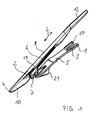
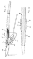
- FIG. 1 an embodiment of the lifter according to the invention for harvested material is shown in perspective.
- the lifter comprises a mounting rail 5, which is provided for attachment of the lifter to a mower of a harvester.
- the support rail 5 at its rear end 1, a recess 3, which is designed as an open towards the rear end 1 slot.
- the recess 3 can be pushed onto a threaded bolt on the mower and secured with a threaded nut (not shown).
- a receptacle 21 on the support rail 5 is pushed onto a mowing finger (not shown) of the cutting deck.
- An advantage of the embodiment with the slot 3 is that an assembly of the mounting rail on different types of fingers is possible, even if the mowing fingers have different lengths and thicknesses. On a mounting surface 17, which surrounds the recess 3, will be discussed later in more detail.
- the lifter profile 8 is preferably connectable to the profile carrier 7 in a plurality of positions spaced apart in the longitudinal direction L of the lifter profile 8.
- the profile carrier 7 in the illustrated embodiment two mutually braced jaws 19, which act on a connecting portion 6 of the lift profile 8.
- the lifter profile 8 per se is an elongated in the longitudinal direction indicated by the double arrow L, approximately rod-shaped component with a head portion 10 at its leading end 4, which is intended to be performed as close to the ground as possible.
- the head portion 10 may be roughly arrow-shaped, widening rearwardly from the tip at the leading end 4, while a middle portion of the lift profile 8 having the connecting portion 6 has a substantially constant cross-section and one end 12 of the lift profile 8 towards the rear slightly narrowing converges.
- a breakthrough 2 of the lift profile 8 will be discussed below with reference to other figures.
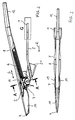
- FIGS. 2 and 3 is the lifter for crop according to FIG. 1 shown in two views, wherein the FIG. 2 in installation position represents a side view and the FIG. 3 a view from above.
- a working direction is represented by the arrow marked R. It is the working direction of the mower, not shown, which generally corresponds to the direction of travel of the harvester. This means that the crop lift moves in the direction of the arrow R through the crop during operation, directing it up and down to supply it to the mower so that the crop is cut on the stalk and no fruit is destroyed.
- the profile carrier 7 can be rotatably adjustable via a rotational axis oriented transversely to the working direction R.
- the lifter profile 8 in a plurality of spaced in its longitudinal direction L positions with the Profile support 7 is connectable.
- the profile carrier 7 cooperates with the connection region 6, which also indicates the maximum adjustment range.
- the clamping jaws 19 of the profile carrier 7, which can be braced against one another work into the connection region 6 in such a way that a connection based essentially on adhesion is produced.
- the lifter profile 8 can be positively connected to the profile carrier 7.
- the connecting portion 6 has a shape which finds a complementary correspondence to the profile carrier 7, so that the formations can interengage accordingly and thus form a form-fitting connection in the longitudinal direction L. As a shape toothing is usually chosen. Due to the positive connection, a stable connection between the profile carrier 7 and the lifter profile 8 is advantageously produced even at low tightening forces on the profile carrier 7, as with a non-positive connection based on clamping force.
- the head portion 10 of the lifter profile 8 is guided on certain crops, such as from the harvest of beans, just above the soil surface and can even penetrate the soil in the short term, which is to prevent that far below the shrub growing pods through the mower be destroyed.
- the lift profile 8 is exposed to particularly heavy loads, which is why the wear on the lift profiles 8 is comparatively high. It has been found to be advantageous to produce the lift profiles 8 from a material that is relatively inexpensive to manufacture, but resistant and in particular readily elastically deformable. For example, when the head portion 10 strikes stones in the ground, the plastic profile 8 is elastically deformed and substantially returns to its original shape.
- the lifter profile 8 preferably has an opening 2, which runs through the lifter profile 8 transversely to the longitudinal or working direction.
- the opening 2 extends in the longitudinal direction L between the front end 4 of the lift profile 8 and the connection region 6, in particular in a transition region between the head region 10 and the connection region 6. Since the profile support 7 holds the lift profile 8 in the connection region 6, it is desirable to that the connection area 6 is not deformed, otherwise the positive connection with the profile carrier 7 could be solved, which could lead to a loss of the lifter profile 8 during harvesting.
- the window 2 represents a weakening of the lift profile 8 in the transition region between the head region 10 and the connection region 6, which advantageously achieves that the head region 10 is deflected to the side under strong force, whereas the connection region 6 is not significantly deformed.
- a power transmission from the head portion 10 to the connecting portion 6 takes place practically not over the weakened by the opening 2 transition region.
- the head region 10 is elastically returned to its original position after elimination of the load.
- the breakthrough 2 can be carried out continuously, but this is not absolutely necessary.
- the aperture 2 is closed by a web 16 whose resistance to deformation is substantially less than that of the head region 10.
- FIG. 4 shows a cross section along the line AA in FIG. 2 and the FIG. 5 shows a section along the line JJ, also in FIG. 2
- the cross section in FIG. 4 shows the profile carrier 7 with the lift profile 8, wherein the lift profile 8 is held by a jaw assembly 15.
- the jaw assembly 15 engages in an area below the opening 2, which is closed by a comparatively thin web 16 at.
- the jaw assembly 15 comprises two oppositely acting and mutually braced jaws 19, as well as three or more clamping jaws would be conceivable, which could act on a correspondingly adapted in the form of connecting region 6 of the lift profile 8.
- the longitudinal direction L of the lift profile 8 is in the FIG. 4 aligned perpendicular to the drawing plane.
- the clamping jaws 19 surround the lifter profile 8 in such a way that a positive connection is provided.
- this positive connection is produced in the illustrated embodiment by inserts 11, which between the clamping jaws 19 and the connecting portion 6 of the lift profile 8 are arranged.
- the inserts 11 are in turn fixed in a form-fitting manner to the clamping jaws 19 in the longitudinal direction L.
- the Einlegemaschinel 1 have on its the connection region 6 of the lift profile 8 side facing a toothing 9, which cooperates with a corresponding counter-toothing of the connecting portion 6.
- the inserts 11 have the advantage that they are interchangeable, whereby lift profiles 8 can be used with different shapes of the connecting portions 6, by each congruent shaped inserts 11 are provided. In addition, the inserts 11 can be significantly better exchange, if it comes to a damage of the toothing due to excessive load.
- FIG. 6 shows a detail labeled G FIG. 2 in a side view.
- FIG. 7 shows the detail according to FIG. 6 in a view from above.
- the support rail 5 has in the illustrated embodiment, the in FIG. 1 shown lift, a recess 3 for attachment to the mower (not shown), wherein the recess 3 is designed as a extending in the direction R elongated hole. According to a preferred embodiment, it is provided that the recess 3 is open to the rear end 1 of the support rail 5 in the working direction R.
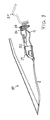
- FIG. 8 is a section along the line HH in FIG. 7 shown enlarged.
- the angular extent is 1.5 degrees in the illustrated embodiment.
- the cutter bar 31 can be seen in a schematic representation, of which a mowing finger 32 is shown above. This is determined by a screw 33 on the cutter bar 31. There are in the plane of, or out of this, several other mowing fingers 32 the cutter bar 31 at a distance from each other assigned. The mowing fingers 32 serve to guide a cutter bar 34, which has mowing blades for separating the crop.
- the illustrated crop lift 30 corresponds to the prior art.
- the attachment of the lifter according to the invention for crop takes place on a mower just.
- the rear end 1 of the support rail 5 can be fixed for example via a screw 33 on the cutter bar 31.
- the support rail 5 is preferably made of a flat material and has flexurally elastic properties.
- the support rail 5 is supported via fastening means in the form of the receptacle 21 on the mowing finger 32.
- the receptacle 21 is connected to the support rail 5, for example by riveting.
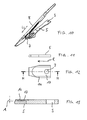
- FIG. 10 is an alternative embodiment with respect to the support rail 5 to that in FIG. 1 illustrated lift shown in perspective.
- the support rail 5 has a recess 3 in the form of a circular bore, which in relation to a slot or slotted back slot according to FIGS. 6 to 8 less expensive to produce.
- FIG. 11 shows a detail of the support rail 5 FIG. 10 in a side view.
- FIG. 12 shows the detail according to FIG. 11 in a view from above.
- the support rail 5 has in the illustrated embodiment, the in FIG. 10 shown lift, a recess 3 for attachment to the mower (not shown), wherein the recess 3 is designed as a circular bore.
- FIG. 13 is a section along the line HH in FIG. 12 shown enlarged.
- To the recess 3 around a mounting surface 17 is incorporated into the surface 14 of the support rail 5 such that by the mounting surface 17 and the surface 14 defined planes include an acute angle A, the angular extent is preferably about 1.5 degrees.
- the profile carrier 7 can be rotatably adjustable via a rotation axis. It is preferably provided that the lifter profile 8 in a plurality of spaced in its longitudinal direction L positions with the profile carrier 7 is connectable. This is the effect of Profile carrier 7 with the connection region 6 together, which also indicates the maximum adjustment range.
- the lift profile 8 is positively connected to the profile carrier 7.
- the connecting portion 6 has a shape which finds a complementary correspondence to the profile carrier 7, so that the formations can interengage accordingly and thus form a form-fitting connection in the longitudinal direction L. As a shape toothing is usually chosen. Due to the positive connection, a stable connection between the profile carrier 7 and the lifter profile 8 is advantageously produced even at low tightening forces on the profile carrier 7.
- the head portion 10 of the lift profile 8 is performed at certain crops, such as from the harvest of beans, just above the ground surface and can even penetrate the soil at short notice.
- the plastic profile 8 is elastically deformed and substantially returns to its original shape.
- the lifter profile 8 preferably has an opening 2, which extends transversely to the longitudinal direction through the lifter profile 8.
- the opening 2 extends in the longitudinal direction L between the front end 4 of the lift profile 8 and the connection region 6, in particular in a transition region between the head region 10 and the connection region 6.
- the window 2 represents a weakening of the lift profile 8 in the transition region between the head region 10 and the connection region 6, which advantageously achieves that the head region 10 is deflected to the side under strong force, whereas the connection region 6 is not significantly deformed.
- a power transmission from the head portion 10 to the connecting portion 6 takes place practically not over the weakened by the opening 2 transition region.
- the head region 10 is elastically returned to its original position after elimination of the load.
- the breakthrough 2 can be carried out continuously, which but not mandatory.
- the opening is closed by a web whose resistance to deformation is substantially lower than in the head region 10.
- FIG. 15 shows a section along the line AA in FIG. 14 , in an enlarged view.
- the section shows the lift profile 8, wherein the lift profile 8 is clamped by two oppositely acting clamping jaws 19 of a jaw assembly.
- the clamping jaws 19 have, on their side facing the connecting region 6 of the lifter profile 8, a toothing 9 which cooperates with a corresponding counter-toothing of the connecting region 6.
- the teeth 9 is given in the longitudinal direction L a predominantly based on positive connection of the components connection.
- To provide the toothing 9 directly to the jaw 19, has the advantage that it can be dispensed with the use of easily loserable items.
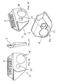
- FIGS. 16 to 19 is the jaw 19 of the lift according to FIG. 14 presented in four different views, which are described here together.
- the toothing 9 has a number of teeth on the inside of a half-shell-shaped receptacle for the connection region of the lifter profile 8 (not shown).
- the recesses 18 and 20 of the jaws 19 distinguish them from those in the FIGS. 1 to 5 and 10 shown jaws.
- the in the FIGS. 16 to 19 shown jaw 19 is provided as seen in the direction R right jaw, which on the profile carrier 7 by means of a screw bolt 23 and a nut 25 (see FIGS. 20 and 21 ) is to be fastened with the first recess 20. A screwing of the two jaws 19 against each other does not occur.
- the formation 22 around the first recess 20 around serves a rotationally positive reception of a screw head 23 ', which is usually four- or hexagonal shaped to facilitate the tightening and loosening of a lock nut 25.
- FIGS. 20 and 21 show the lifter according to the invention according to FIG. 14 in two perspective views.
- the FIG. 20 is the left in the working direction R
- the FIG. 21 the right side in the direction of R visible.
- the in the FIG. 20 Recognizable left jaw 19 also has the second recess of larger diameter than the first recess 20.
- Within the second recess 18 of the right jaw 19 fastened bolt 23 can be seen, which is secured with the nut 25.
- a loosening of the nut 25 and thus a release of the right jaw 19 is possible without the left jaw 19 to solve. Rather, it maintains the preset angle of the lift profile 8 by leaving the relative position of the left jaw 19 to the tread carrier 7 unchanged while the tread 8 is exchanged, for example due to a defect.
- the left jaw 19 is also secured by a bolt 24 through the first recess 20 on the profile carrier, wherein in the FIG. 20 only the bolt head 24 'is visible, which is positively received in the hexagonal shape 22 of the jaw 19.
- the bolt 24 is secured by a nut 26.
- the second recess 18 of the right clamping jaw 19 also recognizes a release of the left jaw 19, while the right jaw remains attached to the profile carrier 7.
- the bolt head 23 ' is positively received in the hexagonal shape 22 of the right jaw 19 to facilitate the loosening and tightening of the nut 25.
Landscapes
- Life Sciences & Earth Sciences (AREA)
- Environmental Sciences (AREA)
- Harvester Elements (AREA)
- Harvesting Machines For Specific Crops (AREA)
- Mutual Connection Of Rods And Tubes (AREA)
- Outside Dividers And Delivering Mechanisms For Harvesters (AREA)
- Agricultural Machines (AREA)
Applications Claiming Priority (2)
| Application Number | Priority Date | Filing Date | Title |
|---|---|---|---|
| DE102012100302A DE102012100302A1 (de) | 2012-01-13 | 2012-01-13 | Heber für Erntegut |
| EP12199207.7A EP2614700B1 (fr) | 2012-01-13 | 2012-12-21 | Levier pour récolte |
Related Parent Applications (2)
| Application Number | Title | Priority Date | Filing Date |
|---|---|---|---|
| EP12199207.7A Division EP2614700B1 (fr) | 2012-01-13 | 2012-12-21 | Levier pour récolte |
| EP12199207.7A Division-Into EP2614700B1 (fr) | 2012-01-13 | 2012-12-21 | Levier pour récolte |
Publications (2)
| Publication Number | Publication Date |
|---|---|
| EP2805601A1 true EP2805601A1 (fr) | 2014-11-26 |
| EP2805601B1 EP2805601B1 (fr) | 2018-06-27 |
Family
ID=47561216
Family Applications (3)
| Application Number | Title | Priority Date | Filing Date |
|---|---|---|---|
| EP14177260.8A Active EP2805600B1 (fr) | 2012-01-13 | 2012-12-21 | Levier pour récolte |
| EP12199207.7A Active EP2614700B1 (fr) | 2012-01-13 | 2012-12-21 | Levier pour récolte |
| EP14177263.2A Active EP2805601B1 (fr) | 2012-01-13 | 2012-12-21 | Levier pour récolte |
Family Applications Before (2)
| Application Number | Title | Priority Date | Filing Date |
|---|---|---|---|
| EP14177260.8A Active EP2805600B1 (fr) | 2012-01-13 | 2012-12-21 | Levier pour récolte |
| EP12199207.7A Active EP2614700B1 (fr) | 2012-01-13 | 2012-12-21 | Levier pour récolte |
Country Status (11)
| Country | Link |
|---|---|
| US (1) | US9220199B2 (fr) |
| EP (3) | EP2805600B1 (fr) |
| AR (1) | AR089499A1 (fr) |
| AU (1) | AU2013200189B2 (fr) |
| BR (1) | BR102013000808B1 (fr) |
| CA (3) | CA2801481C (fr) |
| DE (1) | DE102012100302A1 (fr) |
| ES (3) | ES2683205T3 (fr) |
| HU (3) | HUE039025T2 (fr) |
| RU (1) | RU2528712C2 (fr) |
| TR (1) | TR201810006T4 (fr) |
Families Citing this family (3)
| Publication number | Priority date | Publication date | Assignee | Title |
|---|---|---|---|---|
| CA2748754C (fr) * | 2011-08-11 | 2017-11-07 | Dave Dietrich | Instrument de recolte |
| DE102015101983A1 (de) * | 2015-02-11 | 2016-08-11 | Claas Saulgau Gmbh | Einweiselement für ein Maisgebiss eines Feldhäckslers und Maisgebiss |
| US10299437B2 (en) | 2017-07-17 | 2019-05-28 | Cnh Industrial America Llc | Header for an agricultural vehicle with deformable supports |
Citations (5)
| Publication number | Priority date | Publication date | Assignee | Title |
|---|---|---|---|---|
| DE864637C (de) * | 1950-07-13 | 1953-01-26 | Hermann Hege | AEhrenheber |
| US2734332A (en) * | 1956-02-14 | fisher | ||
| DE1482880A1 (de) * | 1965-09-07 | 1969-10-02 | Gustav Schumacher | AEhrenheber fuer Maehdrescher und Bindemaeher |
| DE2325916A1 (de) | 1973-05-22 | 1974-12-12 | Schumacher | Aehrenheber fuer ein getreidemaehwerk |
| WO2006072158A1 (fr) | 2005-01-06 | 2006-07-13 | Dave Dietrich | Releveur d’epis et attache pour accessoire a epis |
Family Cites Families (16)
| Publication number | Priority date | Publication date | Assignee | Title |
|---|---|---|---|---|
| US2734322A (en) * | 1956-02-14 | Vaughan | ||
| DE320550C (de) * | 1912-11-20 | 1920-04-23 | Lucien Bouchet | Befestigungsvorrichtung fuer die AEhrenheber von Getreidemaehmaschinen |
| US1123632A (en) | 1913-05-06 | 1915-01-05 | John Weisgarber | Grain-lifter. |
| US1202084A (en) | 1916-01-31 | 1916-10-24 | Charles E Merkel | Lifting-guard for harvesters. |
| US1797682A (en) | 1929-06-12 | 1931-03-24 | Gaterman William | Grain-lifter guard for mowing machines |
| US2099471A (en) * | 1937-03-05 | 1937-11-16 | Cheney Weeder Company | Harvester attachment |
| US2294646A (en) * | 1940-09-19 | 1942-09-01 | Young Edward Henry | Down-grain guard for combines |
| US2484704A (en) * | 1944-03-31 | 1949-10-11 | Phillip Hyman | Pickup assembly |
| US2892298A (en) * | 1957-08-05 | 1959-06-30 | Earl J Chaney | Pickup device |
| DE1507366C3 (de) * | 1965-09-07 | 1974-03-14 | Gustav 5231 Eichelhardt Schumacher Ii | Ährenheber für Getreidemähwerke |
| DE3300769A1 (de) | 1983-01-12 | 1984-07-12 | Gustav Schumacher Ii | Aehrenheber fuer fingerbalkenmaehwerke von erntemaschinen |
| SU1440413A1 (ru) * | 1986-12-19 | 1988-11-30 | Украинский научно-исследовательский институт механизации и электрификации сельского хозяйства | Стеблеподъемник уборочной машины |
| FR2618975B1 (fr) * | 1987-08-04 | 1991-06-07 | Bouin Gerard | Dispositif releveur de recolte versee tangentiel a geometrie variable |
| US6442919B1 (en) * | 1998-03-10 | 2002-09-03 | Gustav Schumacher | Grain lifter |
| DE10113107B4 (de) * | 2001-03-15 | 2010-01-21 | Gebr. Schumacher Gerätebaugesellschaft mbH | Ährenheber für Erntemaschinenmähsysteme |
| DE10123248C1 (de) * | 2001-05-12 | 2002-09-19 | Schumacher Gmbh Geb | Ährenheber für Erntemaschinenmähsysteme |
-
2012
- 2012-01-13 DE DE102012100302A patent/DE102012100302A1/de not_active Ceased
- 2012-12-21 EP EP14177260.8A patent/EP2805600B1/fr active Active
- 2012-12-21 HU HUE12199207A patent/HUE039025T2/hu unknown
- 2012-12-21 ES ES14177263.2T patent/ES2683205T3/es active Active
- 2012-12-21 ES ES14177260.8T patent/ES2667810T3/es active Active
- 2012-12-21 EP EP12199207.7A patent/EP2614700B1/fr active Active
- 2012-12-21 TR TR2018/10006T patent/TR201810006T4/tr unknown
- 2012-12-21 HU HUE14177263A patent/HUE040533T2/hu unknown
- 2012-12-21 EP EP14177263.2A patent/EP2805601B1/fr active Active
- 2012-12-21 HU HUE14177260A patent/HUE036871T2/hu unknown
- 2012-12-21 ES ES12199207.7T patent/ES2677819T3/es active Active
- 2012-12-27 AR ARP120105021A patent/AR089499A1/es active IP Right Grant
-
2013
- 2013-01-09 CA CA2801481A patent/CA2801481C/fr active Active
- 2013-01-09 CA CA2892196A patent/CA2892196C/fr active Active
- 2013-01-09 CA CA2892075A patent/CA2892075C/fr active Active
- 2013-01-10 RU RU2013100990/13A patent/RU2528712C2/ru active
- 2013-01-11 AU AU2013200189A patent/AU2013200189B2/en not_active Ceased
- 2013-01-11 BR BR102013000808-7A patent/BR102013000808B1/pt active IP Right Grant
- 2013-01-11 US US13/739,281 patent/US9220199B2/en active Active
Patent Citations (5)
| Publication number | Priority date | Publication date | Assignee | Title |
|---|---|---|---|---|
| US2734332A (en) * | 1956-02-14 | fisher | ||
| DE864637C (de) * | 1950-07-13 | 1953-01-26 | Hermann Hege | AEhrenheber |
| DE1482880A1 (de) * | 1965-09-07 | 1969-10-02 | Gustav Schumacher | AEhrenheber fuer Maehdrescher und Bindemaeher |
| DE2325916A1 (de) | 1973-05-22 | 1974-12-12 | Schumacher | Aehrenheber fuer ein getreidemaehwerk |
| WO2006072158A1 (fr) | 2005-01-06 | 2006-07-13 | Dave Dietrich | Releveur d’epis et attache pour accessoire a epis |
Also Published As
| Publication number | Publication date |
|---|---|
| CA2892075C (fr) | 2017-11-28 |
| DE102012100302A1 (de) | 2013-07-18 |
| CA2892196C (fr) | 2017-02-07 |
| TR201810006T4 (tr) | 2018-08-27 |
| CA2892075A1 (fr) | 2013-07-13 |
| EP2805601B1 (fr) | 2018-06-27 |
| ES2683205T3 (es) | 2018-09-25 |
| EP2614700A2 (fr) | 2013-07-17 |
| US9220199B2 (en) | 2015-12-29 |
| CA2801481A1 (fr) | 2013-07-13 |
| EP2614700B1 (fr) | 2018-04-25 |
| EP2805600B1 (fr) | 2018-02-14 |
| CA2801481C (fr) | 2016-09-06 |
| HUE040533T2 (hu) | 2019-03-28 |
| RU2528712C2 (ru) | 2014-09-20 |
| AU2013200189A1 (en) | 2013-08-01 |
| US20130180226A1 (en) | 2013-07-18 |
| BR102013000808A2 (pt) | 2017-05-02 |
| ES2667810T3 (es) | 2018-05-14 |
| HUE039025T2 (hu) | 2018-12-28 |
| CA2892196A1 (fr) | 2013-07-13 |
| EP2805600A1 (fr) | 2014-11-26 |
| BR102013000808B1 (pt) | 2019-08-06 |
| AU2013200189B2 (en) | 2014-09-18 |
| ES2677819T3 (es) | 2018-08-07 |
| RU2013100990A (ru) | 2014-07-20 |
| AR089499A1 (es) | 2014-08-27 |
| BR102013000808A8 (pt) | 2018-03-06 |
| EP2614700A3 (fr) | 2013-09-04 |
| HUE036871T2 (hu) | 2018-08-28 |
Similar Documents
| Publication | Publication Date | Title |
|---|---|---|
| EP0073359B1 (fr) | Dispositif de verrouillage pour faucheuse | |
| DD226747A5 (de) | Reihenabtastvorrichtung fuer eine erntemaschine | |
| EP1029436B1 (fr) | Fixation, faucheuse et véhicule resp. appareil de travail | |
| DE102007007985B4 (de) | Schneidwerk zum Abschneiden von stängeligem Schnittgut | |
| EP1584226A2 (fr) | Dispositif de coupe pour /dans des machines de récolte | |
| DE10128101B4 (de) | Ährenheber | |
| EP2614700B1 (fr) | Levier pour récolte | |
| DE102013011088B4 (de) | Messer für einen Feldhäcksler und Exzenterwerkzeug zur Positionsjustierung | |
| AT392388B (de) | Bodenfraese | |
| EP3449710A1 (fr) | Dispositif de travail agricole | |
| DE102008045132A1 (de) | Säscharanordnung | |
| EP3354126B1 (fr) | Couteau et tambour de hachoir pour une ramasseuse-hacheuse | |
| DE2855234A1 (de) | Maehfinger fuer fingerbalkenmaehwerke | |
| DE3726967A1 (de) | Erntegeraet zum ernten von mais oder anderen koernerfruechten | |
| EP3226673A1 (fr) | Système de réglage de l'age d'un outil de travail du sol | |
| EP3653042A1 (fr) | Dispositif de scie pivotant destiné au découpage des plantes | |
| DE202005007424U1 (de) | Mähbalken für Scheibenmähwerke | |
| DE202015104423U1 (de) | Messersatz und Mähaggregat mit einer Vielzahl von Messersätzen | |
| DE3617003A1 (de) | Schneideinrichtung fuer halm- und blattgut | |
| EP1769663A1 (fr) | Adaptateur de coupe pour une motofaucheuse | |
| EP3235358A1 (fr) | Pointe de bande destinee a etre utilisee dans un systeme de soc pour le traitement du sol | |
| DE102009039670B9 (de) | Ährenheber | |
| DE3119938A1 (de) | "maehwerk fuer maehdrescher" | |
| DE2945960A1 (de) | Maehfinger fuer fingerbalkenmaehwerke | |
| DE102010017656B4 (de) | Vorrichtung zum Abschneiden und Zerschneiden von Schnittgut |
Legal Events
| Date | Code | Title | Description |
|---|---|---|---|
| PUAI | Public reference made under article 153(3) epc to a published international application that has entered the european phase |
Free format text: ORIGINAL CODE: 0009012 |
|
| 17P | Request for examination filed |
Effective date: 20140716 |
|
| AC | Divisional application: reference to earlier application |
Ref document number: 2614700 Country of ref document: EP Kind code of ref document: P |
|
| AK | Designated contracting states |
Kind code of ref document: A1 Designated state(s): AL AT BE BG CH CY CZ DE DK EE ES FI FR GB GR HR HU IE IS IT LI LT LU LV MC MK MT NL NO PL PT RO RS SE SI SK SM TR |
|
| R17P | Request for examination filed (corrected) |
Effective date: 20150522 |
|
| RBV | Designated contracting states (corrected) |
Designated state(s): AL AT BE BG CH CY CZ DE DK EE ES FI FR GB GR HR HU IE IS IT LI LT LU LV MC MK MT NL NO PL PT RO RS SE SI SK SM TR |
|
| STAA | Information on the status of an ep patent application or granted ep patent |
Free format text: STATUS: EXAMINATION IS IN PROGRESS |
|
| 17Q | First examination report despatched |
Effective date: 20170627 |
|
| GRAP | Despatch of communication of intention to grant a patent |
Free format text: ORIGINAL CODE: EPIDOSNIGR1 |
|
| STAA | Information on the status of an ep patent application or granted ep patent |
Free format text: STATUS: GRANT OF PATENT IS INTENDED |
|
| INTG | Intention to grant announced |
Effective date: 20180119 |
|
| GRAS | Grant fee paid |
Free format text: ORIGINAL CODE: EPIDOSNIGR3 |
|
| GRAA | (expected) grant |
Free format text: ORIGINAL CODE: 0009210 |
|
| STAA | Information on the status of an ep patent application or granted ep patent |
Free format text: STATUS: THE PATENT HAS BEEN GRANTED |
|
| AC | Divisional application: reference to earlier application |
Ref document number: 2614700 Country of ref document: EP Kind code of ref document: P |
|
| AK | Designated contracting states |
Kind code of ref document: B1 Designated state(s): AL AT BE BG CH CY CZ DE DK EE ES FI FR GB GR HR HU IE IS IT LI LT LU LV MC MK MT NL NO PL PT RO RS SE SI SK SM TR |
|
| REG | Reference to a national code |
Ref country code: GB Ref legal event code: FG4D Free format text: NOT ENGLISH |
|
| REG | Reference to a national code |
Ref country code: AT Ref legal event code: REF Ref document number: 1011484 Country of ref document: AT Kind code of ref document: T Effective date: 20180715 |
|
| REG | Reference to a national code |
Ref country code: IE Ref legal event code: FG4D Free format text: LANGUAGE OF EP DOCUMENT: GERMAN |
|
| REG | Reference to a national code |
Ref country code: DE Ref legal event code: R096 Ref document number: 502012012958 Country of ref document: DE |
|
| REG | Reference to a national code |
Ref country code: ES Ref legal event code: FG2A Ref document number: 2683205 Country of ref document: ES Kind code of ref document: T3 Effective date: 20180925 |
|
| PG25 | Lapsed in a contracting state [announced via postgrant information from national office to epo] |
Ref country code: LT Free format text: LAPSE BECAUSE OF FAILURE TO SUBMIT A TRANSLATION OF THE DESCRIPTION OR TO PAY THE FEE WITHIN THE PRESCRIBED TIME-LIMIT Effective date: 20180627 Ref country code: SE Free format text: LAPSE BECAUSE OF FAILURE TO SUBMIT A TRANSLATION OF THE DESCRIPTION OR TO PAY THE FEE WITHIN THE PRESCRIBED TIME-LIMIT Effective date: 20180627 Ref country code: NO Free format text: LAPSE BECAUSE OF FAILURE TO SUBMIT A TRANSLATION OF THE DESCRIPTION OR TO PAY THE FEE WITHIN THE PRESCRIBED TIME-LIMIT Effective date: 20180927 Ref country code: FI Free format text: LAPSE BECAUSE OF FAILURE TO SUBMIT A TRANSLATION OF THE DESCRIPTION OR TO PAY THE FEE WITHIN THE PRESCRIBED TIME-LIMIT Effective date: 20180627 Ref country code: BG Free format text: LAPSE BECAUSE OF FAILURE TO SUBMIT A TRANSLATION OF THE DESCRIPTION OR TO PAY THE FEE WITHIN THE PRESCRIBED TIME-LIMIT Effective date: 20180927 |
|
| REG | Reference to a national code |
Ref country code: NL Ref legal event code: MP Effective date: 20180627 |
|
| REG | Reference to a national code |
Ref country code: LT Ref legal event code: MG4D |
|
| PG25 | Lapsed in a contracting state [announced via postgrant information from national office to epo] |
Ref country code: LV Free format text: LAPSE BECAUSE OF FAILURE TO SUBMIT A TRANSLATION OF THE DESCRIPTION OR TO PAY THE FEE WITHIN THE PRESCRIBED TIME-LIMIT Effective date: 20180627 Ref country code: GR Free format text: LAPSE BECAUSE OF FAILURE TO SUBMIT A TRANSLATION OF THE DESCRIPTION OR TO PAY THE FEE WITHIN THE PRESCRIBED TIME-LIMIT Effective date: 20180928 Ref country code: HR Free format text: LAPSE BECAUSE OF FAILURE TO SUBMIT A TRANSLATION OF THE DESCRIPTION OR TO PAY THE FEE WITHIN THE PRESCRIBED TIME-LIMIT Effective date: 20180627 Ref country code: RS Free format text: LAPSE BECAUSE OF FAILURE TO SUBMIT A TRANSLATION OF THE DESCRIPTION OR TO PAY THE FEE WITHIN THE PRESCRIBED TIME-LIMIT Effective date: 20180627 |
|
| PG25 | Lapsed in a contracting state [announced via postgrant information from national office to epo] |
Ref country code: NL Free format text: LAPSE BECAUSE OF FAILURE TO SUBMIT A TRANSLATION OF THE DESCRIPTION OR TO PAY THE FEE WITHIN THE PRESCRIBED TIME-LIMIT Effective date: 20180627 |
|
| PG25 | Lapsed in a contracting state [announced via postgrant information from national office to epo] |
Ref country code: IS Free format text: LAPSE BECAUSE OF FAILURE TO SUBMIT A TRANSLATION OF THE DESCRIPTION OR TO PAY THE FEE WITHIN THE PRESCRIBED TIME-LIMIT Effective date: 20181027 Ref country code: PL Free format text: LAPSE BECAUSE OF FAILURE TO SUBMIT A TRANSLATION OF THE DESCRIPTION OR TO PAY THE FEE WITHIN THE PRESCRIBED TIME-LIMIT Effective date: 20180627 Ref country code: EE Free format text: LAPSE BECAUSE OF FAILURE TO SUBMIT A TRANSLATION OF THE DESCRIPTION OR TO PAY THE FEE WITHIN THE PRESCRIBED TIME-LIMIT Effective date: 20180627 Ref country code: CZ Free format text: LAPSE BECAUSE OF FAILURE TO SUBMIT A TRANSLATION OF THE DESCRIPTION OR TO PAY THE FEE WITHIN THE PRESCRIBED TIME-LIMIT Effective date: 20180627 Ref country code: RO Free format text: LAPSE BECAUSE OF FAILURE TO SUBMIT A TRANSLATION OF THE DESCRIPTION OR TO PAY THE FEE WITHIN THE PRESCRIBED TIME-LIMIT Effective date: 20180627 Ref country code: SK Free format text: LAPSE BECAUSE OF FAILURE TO SUBMIT A TRANSLATION OF THE DESCRIPTION OR TO PAY THE FEE WITHIN THE PRESCRIBED TIME-LIMIT Effective date: 20180627 |
|
| PG25 | Lapsed in a contracting state [announced via postgrant information from national office to epo] |
Ref country code: SM Free format text: LAPSE BECAUSE OF FAILURE TO SUBMIT A TRANSLATION OF THE DESCRIPTION OR TO PAY THE FEE WITHIN THE PRESCRIBED TIME-LIMIT Effective date: 20180627 |
|
| REG | Reference to a national code |
Ref country code: HU Ref legal event code: AG4A Ref document number: E040533 Country of ref document: HU Ref country code: DE Ref legal event code: R097 Ref document number: 502012012958 Country of ref document: DE |
|
| PLBE | No opposition filed within time limit |
Free format text: ORIGINAL CODE: 0009261 |
|
| STAA | Information on the status of an ep patent application or granted ep patent |
Free format text: STATUS: NO OPPOSITION FILED WITHIN TIME LIMIT |
|
| PG25 | Lapsed in a contracting state [announced via postgrant information from national office to epo] |
Ref country code: DK Free format text: LAPSE BECAUSE OF FAILURE TO SUBMIT A TRANSLATION OF THE DESCRIPTION OR TO PAY THE FEE WITHIN THE PRESCRIBED TIME-LIMIT Effective date: 20180627 |
|
| 26N | No opposition filed |
Effective date: 20190328 |
|
| REG | Reference to a national code |
Ref country code: CH Ref legal event code: PL |
|
| GBPC | Gb: european patent ceased through non-payment of renewal fee |
Effective date: 20181221 |
|
| PG25 | Lapsed in a contracting state [announced via postgrant information from national office to epo] |
Ref country code: MC Free format text: LAPSE BECAUSE OF FAILURE TO SUBMIT A TRANSLATION OF THE DESCRIPTION OR TO PAY THE FEE WITHIN THE PRESCRIBED TIME-LIMIT Effective date: 20180627 Ref country code: LU Free format text: LAPSE BECAUSE OF NON-PAYMENT OF DUE FEES Effective date: 20181221 Ref country code: SI Free format text: LAPSE BECAUSE OF FAILURE TO SUBMIT A TRANSLATION OF THE DESCRIPTION OR TO PAY THE FEE WITHIN THE PRESCRIBED TIME-LIMIT Effective date: 20180627 |
|
| REG | Reference to a national code |
Ref country code: IE Ref legal event code: MM4A |
|
| REG | Reference to a national code |
Ref country code: BE Ref legal event code: MM Effective date: 20181231 |
|
| PG25 | Lapsed in a contracting state [announced via postgrant information from national office to epo] |
Ref country code: IE Free format text: LAPSE BECAUSE OF NON-PAYMENT OF DUE FEES Effective date: 20181221 |
|
| PG25 | Lapsed in a contracting state [announced via postgrant information from national office to epo] |
Ref country code: AL Free format text: LAPSE BECAUSE OF FAILURE TO SUBMIT A TRANSLATION OF THE DESCRIPTION OR TO PAY THE FEE WITHIN THE PRESCRIBED TIME-LIMIT Effective date: 20180627 Ref country code: BE Free format text: LAPSE BECAUSE OF NON-PAYMENT OF DUE FEES Effective date: 20181231 |
|
| PG25 | Lapsed in a contracting state [announced via postgrant information from national office to epo] |
Ref country code: GB Free format text: LAPSE BECAUSE OF NON-PAYMENT OF DUE FEES Effective date: 20181221 Ref country code: CH Free format text: LAPSE BECAUSE OF NON-PAYMENT OF DUE FEES Effective date: 20181231 Ref country code: LI Free format text: LAPSE BECAUSE OF NON-PAYMENT OF DUE FEES Effective date: 20181231 |
|
| PG25 | Lapsed in a contracting state [announced via postgrant information from national office to epo] |
Ref country code: MT Free format text: LAPSE BECAUSE OF FAILURE TO SUBMIT A TRANSLATION OF THE DESCRIPTION OR TO PAY THE FEE WITHIN THE PRESCRIBED TIME-LIMIT Effective date: 20180627 |
|
| REG | Reference to a national code |
Ref country code: AT Ref legal event code: MM01 Ref document number: 1011484 Country of ref document: AT Kind code of ref document: T Effective date: 20181221 |
|
| PG25 | Lapsed in a contracting state [announced via postgrant information from national office to epo] |
Ref country code: AT Free format text: LAPSE BECAUSE OF NON-PAYMENT OF DUE FEES Effective date: 20181221 |
|
| PG25 | Lapsed in a contracting state [announced via postgrant information from national office to epo] |
Ref country code: PT Free format text: LAPSE BECAUSE OF FAILURE TO SUBMIT A TRANSLATION OF THE DESCRIPTION OR TO PAY THE FEE WITHIN THE PRESCRIBED TIME-LIMIT Effective date: 20180627 |
|
| PG25 | Lapsed in a contracting state [announced via postgrant information from national office to epo] |
Ref country code: MK Free format text: LAPSE BECAUSE OF NON-PAYMENT OF DUE FEES Effective date: 20180627 Ref country code: CY Free format text: LAPSE BECAUSE OF FAILURE TO SUBMIT A TRANSLATION OF THE DESCRIPTION OR TO PAY THE FEE WITHIN THE PRESCRIBED TIME-LIMIT Effective date: 20180627 |
|
| PGFP | Annual fee paid to national office [announced via postgrant information from national office to epo] |
Ref country code: FR Payment date: 20211220 Year of fee payment: 10 |
|
| PGFP | Annual fee paid to national office [announced via postgrant information from national office to epo] |
Ref country code: HU Payment date: 20211220 Year of fee payment: 10 |
|
| PGFP | Annual fee paid to national office [announced via postgrant information from national office to epo] |
Ref country code: DE Payment date: 20211220 Year of fee payment: 10 |
|
| PGFP | Annual fee paid to national office [announced via postgrant information from national office to epo] |
Ref country code: TR Payment date: 20211216 Year of fee payment: 10 Ref country code: IT Payment date: 20211230 Year of fee payment: 10 Ref country code: ES Payment date: 20220119 Year of fee payment: 10 |
|
| REG | Reference to a national code |
Ref country code: DE Ref legal event code: R119 Ref document number: 502012012958 Country of ref document: DE |
|
| PG25 | Lapsed in a contracting state [announced via postgrant information from national office to epo] |
Ref country code: DE Free format text: LAPSE BECAUSE OF NON-PAYMENT OF DUE FEES Effective date: 20230701 |
|
| PG25 | Lapsed in a contracting state [announced via postgrant information from national office to epo] |
Ref country code: HU Free format text: LAPSE BECAUSE OF NON-PAYMENT OF DUE FEES Effective date: 20221222 Ref country code: FR Free format text: LAPSE BECAUSE OF NON-PAYMENT OF DUE FEES Effective date: 20221231 |
|
| PG25 | Lapsed in a contracting state [announced via postgrant information from national office to epo] |
Ref country code: IT Free format text: LAPSE BECAUSE OF NON-PAYMENT OF DUE FEES Effective date: 20221221 |
|
| REG | Reference to a national code |
Ref country code: ES Ref legal event code: FD2A Effective date: 20240206 |
|
| PG25 | Lapsed in a contracting state [announced via postgrant information from national office to epo] |
Ref country code: ES Free format text: LAPSE BECAUSE OF NON-PAYMENT OF DUE FEES Effective date: 20221222 |
|
| PG25 | Lapsed in a contracting state [announced via postgrant information from national office to epo] |
Ref country code: ES Free format text: LAPSE BECAUSE OF NON-PAYMENT OF DUE FEES Effective date: 20221222 |