EP2805601A1 - Lifter for crops - Google Patents
Lifter for crops Download PDFInfo
- Publication number
- EP2805601A1 EP2805601A1 EP14177263.2A EP14177263A EP2805601A1 EP 2805601 A1 EP2805601 A1 EP 2805601A1 EP 14177263 A EP14177263 A EP 14177263A EP 2805601 A1 EP2805601 A1 EP 2805601A1
- Authority
- EP
- European Patent Office
- Prior art keywords
- profile
- lifter
- lift
- recess
- crop
- Prior art date
- Legal status (The legal status is an assumption and is not a legal conclusion. Google has not performed a legal analysis and makes no representation as to the accuracy of the status listed.)
- Granted
Links
- 230000001154 acute effect Effects 0.000 claims abstract description 9
- 238000003306 harvesting Methods 0.000 description 6
- 230000007704 transition Effects 0.000 description 6
- 230000015572 biosynthetic process Effects 0.000 description 4
- 235000013339 cereals Nutrition 0.000 description 4
- 235000013399 edible fruits Nutrition 0.000 description 4
- 238000005755 formation reaction Methods 0.000 description 4
- 239000000463 material Substances 0.000 description 4
- 239000002689 soil Substances 0.000 description 4
- 235000010627 Phaseolus vulgaris Nutrition 0.000 description 3
- 244000046052 Phaseolus vulgaris Species 0.000 description 3
- 238000005520 cutting process Methods 0.000 description 3
- 230000005489 elastic deformation Effects 0.000 description 3
- 230000008030 elimination Effects 0.000 description 3
- 238000003379 elimination reaction Methods 0.000 description 3
- 235000021374 legumes Nutrition 0.000 description 3
- 239000010902 straw Substances 0.000 description 3
- 230000003313 weakening effect Effects 0.000 description 3
- 230000005540 biological transmission Effects 0.000 description 2
- 230000000295 complement effect Effects 0.000 description 2
- 230000002950 deficient Effects 0.000 description 2
- 210000005069 ears Anatomy 0.000 description 2
- 230000000694 effects Effects 0.000 description 2
- 244000068988 Glycine max Species 0.000 description 1
- 235000010469 Glycine max Nutrition 0.000 description 1
- 230000006978 adaptation Effects 0.000 description 1
- 238000005266 casting Methods 0.000 description 1
- 150000001875 compounds Chemical class 0.000 description 1
- 230000007547 defect Effects 0.000 description 1
- 230000001419 dependent effect Effects 0.000 description 1
- 238000011161 development Methods 0.000 description 1
- 230000018109 developmental process Effects 0.000 description 1
- 238000009434 installation Methods 0.000 description 1
- 238000004519 manufacturing process Methods 0.000 description 1
- 230000004048 modification Effects 0.000 description 1
- 238000012986 modification Methods 0.000 description 1
- 239000011435 rock Substances 0.000 description 1
- 238000003466 welding Methods 0.000 description 1
Images


Classifications
-
- A—HUMAN NECESSITIES
- A01—AGRICULTURE; FORESTRY; ANIMAL HUSBANDRY; HUNTING; TRAPPING; FISHING
- A01D—HARVESTING; MOWING
- A01D65/00—Grain-crop lifters
- A01D65/02—Lifting fingers
Definitions
- the invention relates to a lift for crop for a mower of a harvester, comprising a mounting rail attachable to the mower, wherein the support rail has a profile support and wherein a lift profile is provided on the profile support, or wherein the lift profile is connected to the support rail.
- a so-called ear lifter which slides with the front part of the support rail on which a Halmheber is attached, slides over the ground or moves just above the ground and with the Halmheber on the ground lying culms of the crop, so that they can be cut off by the cutting unit of the mower and thus the ears can be supplied, for example, a threshing unit.
- Such an ear lifter shows the DE 23 25 916 A in which the straw lifter consists entirely of a U-shaped profile part whose limbs increasingly shorten starting from the welding of the straw lifter to the mounting rail to the free end of the straw lifter.
- the WO 2006/072158 A1 relates to an ear lifter, wherein it is proposed to releasably arrange a lifter profile on a supporting structure so that the lifter profile is individually exchangeable and replacement of the entire crop lifter is avoided.
- a disadvantage is that an exchange of the supporting structure, if this is still necessary, is complicated and that the frequency of failure of the lift profiles per se is not reduced.
- An object of the invention is to provide a lifter for crop, which is less susceptible to failure and / or with less effort repairable settable.
- lifter for crops is intended to express that no restriction is made to a specific crop, such as cereal ears or legumes.
- the lifters for crops according to the invention are suitable as lifters for any crop. Special features in the processing of special crops will be discussed in detail.
- the crop lift according to the invention for a mower deck of a harvesting machine comprises a mounting rail which can be fastened to the mower and has a profile carrier for a lift profile, as a rule at a front end of the carrier rail in one working direction.
- the working direction usually corresponds to the direction of travel of the harvester.
- the lift profile is preferably provided for releasable attachment to the profile carrier.
- the lifter profile in a plurality of spaced apart in the longitudinal direction of the lifter profile positions with the profile carrier is connectable.
- the longitudinal direction corresponds to a main extension direction of the usually substantially rod-shaped or blade-shaped lift profile.
- the lifter for crops advantageously allows an adjustment of the lifter profile in the longitudinal direction and thus offers a possibility to adjust the height of the leading tip of the lifter profile above the ground particularly accurately and to guide them with the shortest possible distance above the ground.
- the compound in discrete positions along the lift profile can be produced and further particularly preferred as a positive connection. This means in particular a positive connection between the lift profile and the profile carrier in the longitudinal direction of the lift profile, since in this direction the greatest force acts on the connection.
- the adjustability in discrete positions that is to say in finite, countable positions, has the advantage over stepless adjustability that, given a known distance of the positions from one another, adjustment to a certain extent is made possible without the aid of measuring means.
- the lift profile has a connection region, wherein the connection region extends in the longitudinal direction along the lift profile and wherein fastening means on the profile support interact with the connection region.
- the fastening means on a jaw assembly and / or a toothing are provided on a jaw.
- the corresponding clamping jaw can be produced, for example, in one piece with toothing, in particular as a casting or injection-molded part.
- the toothing could be formed on at least one insert, wherein at least one jaw of the profile carrier receives an insert form-fitting manner.
- the lift profile in the connection region has a counter-toothing, wherein the Schmidtveriereung cooperates with the toothing on the profile carrier.
- the profile carrier is rotatably adjustable via a rotational axis aligned transversely to the working direction.
- the profile carrier are made of a stable material, which is particularly well elastically deformable without significantly plastically deform.
- the lift profile preferably has a leading end in the direction of work, wherein a breakthrough in the lift profile to facilitate elastic deformation of the lift profile is provided upon application of force to the leading end.
- the breakthrough causes a buckling of the lift profile in the area of the opening, which represents a structural weakening and facilitates elastic deformation.
- the opening is arranged at least in sections between the leading end and a connection region for attachment to a profile carrier.
- the aperture has a main extension direction along a longitudinal direction of the lift profile.
- the breakthrough is at least twice as long, in particular in the longitudinal direction, as transverse to the longitudinal direction.
- the breakthrough runs at its ends in the longitudinal direction at an acute angle.
- the opening is closed by a web, wherein the web of a deformation of the opening opposes no significant resistance.
- the object of the invention which solves the problem, is a lifter for crop for a mower of a harvester comprising a mounting rail attachable to the mower, wherein a lifter profile is connected to the mounting rail, wherein the mounting rail has a recess for attachment to the mower, and wherein a mounting surface is incorporated into the surface of the mounting rail around the recess such that planes defined by the mounting surface and the surface form an acute angle.
- An attachment surface is that surface on which the head of a threaded bolt or a threaded nut acts when tightening a screw connection. The corresponding surfaces on the head or nut are aligned parallel to the surface of the mounting rail and thus tilted at the acute angle to the mounting surface.
- the acute angle has an angular extent of less than 5 degrees, preferably less than 3 degrees and most preferably about 1.5 degrees. Angles of less than 0.5 degrees are rather too shallow to allow the inventive technical effect to be achieved.
- the recess is designed as a slot extending in the working direction and / or the recess is open towards a rear end of the mounting rail in the working direction.
- This is particularly advantageous disassembly and assembly of the lifter according to the invention without a complete unscrewing of the bolt from the mother possible.
- the support rail on a receptacle for a mowing finger on the mower of the harvester With this recording, the lifter is pushed onto the mowing finger pointing forward in the working direction.
- the crop lift according to the last described subject invention may, as well as the previously described articles, have a removable lift profile. Likewise, however, should also include one-piece lift for crop, in which the lift profile is firmly connected to the support rail.
- a lifter profile for releasable attachment to the profile carrier is provided by a jaw assembly with two jaws.
- the lift is an embodiment of the lift described above.
- At least one of the two jaws is releasably, while the other of the two jaws remains fixed to the profile carrier.
- the clamping jaws are each fastened to the profile carrier with a separate fastening means.
- the other one remains firmly connected to the profile carrier.
- the jaws each have a first recess for fastening receiving a bolt and a second recess as access to a bolt of the other jaw on.
- the second recess advantageously allows the bolt of each other jaw with a counter element, so for example a nut to secure the profile support.
- the first recordings each have a smaller bore than the second recordings, so that attachment only with the first recordings is possible.
- the first receptacles may preferably correspond to a shape corresponding to the head shape of the bolt head to facilitate the tightening of the nut.
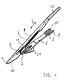
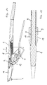
- FIG. 1 an embodiment of the lifter according to the invention for harvested material is shown in perspective.
- the lifter comprises a mounting rail 5, which is provided for attachment of the lifter to a mower of a harvester.
- the support rail 5 at its rear end 1, a recess 3, which is designed as an open towards the rear end 1 slot.
- the recess 3 can be pushed onto a threaded bolt on the mower and secured with a threaded nut (not shown).
- a receptacle 21 on the support rail 5 is pushed onto a mowing finger (not shown) of the cutting deck.
- An advantage of the embodiment with the slot 3 is that an assembly of the mounting rail on different types of fingers is possible, even if the mowing fingers have different lengths and thicknesses. On a mounting surface 17, which surrounds the recess 3, will be discussed later in more detail.
- the lifter profile 8 is preferably connectable to the profile carrier 7 in a plurality of positions spaced apart in the longitudinal direction L of the lifter profile 8.
- the profile carrier 7 in the illustrated embodiment two mutually braced jaws 19, which act on a connecting portion 6 of the lift profile 8.
- the lifter profile 8 per se is an elongated in the longitudinal direction indicated by the double arrow L, approximately rod-shaped component with a head portion 10 at its leading end 4, which is intended to be performed as close to the ground as possible.
- the head portion 10 may be roughly arrow-shaped, widening rearwardly from the tip at the leading end 4, while a middle portion of the lift profile 8 having the connecting portion 6 has a substantially constant cross-section and one end 12 of the lift profile 8 towards the rear slightly narrowing converges.
- a breakthrough 2 of the lift profile 8 will be discussed below with reference to other figures.
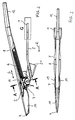
- FIGS. 2 and 3 is the lifter for crop according to FIG. 1 shown in two views, wherein the FIG. 2 in installation position represents a side view and the FIG. 3 a view from above.
- a working direction is represented by the arrow marked R. It is the working direction of the mower, not shown, which generally corresponds to the direction of travel of the harvester. This means that the crop lift moves in the direction of the arrow R through the crop during operation, directing it up and down to supply it to the mower so that the crop is cut on the stalk and no fruit is destroyed.
- the profile carrier 7 can be rotatably adjustable via a rotational axis oriented transversely to the working direction R.
- the lifter profile 8 in a plurality of spaced in its longitudinal direction L positions with the Profile support 7 is connectable.
- the profile carrier 7 cooperates with the connection region 6, which also indicates the maximum adjustment range.
- the clamping jaws 19 of the profile carrier 7, which can be braced against one another work into the connection region 6 in such a way that a connection based essentially on adhesion is produced.
- the lifter profile 8 can be positively connected to the profile carrier 7.
- the connecting portion 6 has a shape which finds a complementary correspondence to the profile carrier 7, so that the formations can interengage accordingly and thus form a form-fitting connection in the longitudinal direction L. As a shape toothing is usually chosen. Due to the positive connection, a stable connection between the profile carrier 7 and the lifter profile 8 is advantageously produced even at low tightening forces on the profile carrier 7, as with a non-positive connection based on clamping force.
- the head portion 10 of the lifter profile 8 is guided on certain crops, such as from the harvest of beans, just above the soil surface and can even penetrate the soil in the short term, which is to prevent that far below the shrub growing pods through the mower be destroyed.
- the lift profile 8 is exposed to particularly heavy loads, which is why the wear on the lift profiles 8 is comparatively high. It has been found to be advantageous to produce the lift profiles 8 from a material that is relatively inexpensive to manufacture, but resistant and in particular readily elastically deformable. For example, when the head portion 10 strikes stones in the ground, the plastic profile 8 is elastically deformed and substantially returns to its original shape.
- the lifter profile 8 preferably has an opening 2, which runs through the lifter profile 8 transversely to the longitudinal or working direction.
- the opening 2 extends in the longitudinal direction L between the front end 4 of the lift profile 8 and the connection region 6, in particular in a transition region between the head region 10 and the connection region 6. Since the profile support 7 holds the lift profile 8 in the connection region 6, it is desirable to that the connection area 6 is not deformed, otherwise the positive connection with the profile carrier 7 could be solved, which could lead to a loss of the lifter profile 8 during harvesting.
- the window 2 represents a weakening of the lift profile 8 in the transition region between the head region 10 and the connection region 6, which advantageously achieves that the head region 10 is deflected to the side under strong force, whereas the connection region 6 is not significantly deformed.
- a power transmission from the head portion 10 to the connecting portion 6 takes place practically not over the weakened by the opening 2 transition region.
- the head region 10 is elastically returned to its original position after elimination of the load.
- the breakthrough 2 can be carried out continuously, but this is not absolutely necessary.
- the aperture 2 is closed by a web 16 whose resistance to deformation is substantially less than that of the head region 10.
- FIG. 4 shows a cross section along the line AA in FIG. 2 and the FIG. 5 shows a section along the line JJ, also in FIG. 2
- the cross section in FIG. 4 shows the profile carrier 7 with the lift profile 8, wherein the lift profile 8 is held by a jaw assembly 15.
- the jaw assembly 15 engages in an area below the opening 2, which is closed by a comparatively thin web 16 at.
- the jaw assembly 15 comprises two oppositely acting and mutually braced jaws 19, as well as three or more clamping jaws would be conceivable, which could act on a correspondingly adapted in the form of connecting region 6 of the lift profile 8.
- the longitudinal direction L of the lift profile 8 is in the FIG. 4 aligned perpendicular to the drawing plane.
- the clamping jaws 19 surround the lifter profile 8 in such a way that a positive connection is provided.
- this positive connection is produced in the illustrated embodiment by inserts 11, which between the clamping jaws 19 and the connecting portion 6 of the lift profile 8 are arranged.
- the inserts 11 are in turn fixed in a form-fitting manner to the clamping jaws 19 in the longitudinal direction L.
- the Einlegemaschinel 1 have on its the connection region 6 of the lift profile 8 side facing a toothing 9, which cooperates with a corresponding counter-toothing of the connecting portion 6.
- the inserts 11 have the advantage that they are interchangeable, whereby lift profiles 8 can be used with different shapes of the connecting portions 6, by each congruent shaped inserts 11 are provided. In addition, the inserts 11 can be significantly better exchange, if it comes to a damage of the toothing due to excessive load.
- FIG. 6 shows a detail labeled G FIG. 2 in a side view.
- FIG. 7 shows the detail according to FIG. 6 in a view from above.
- the support rail 5 has in the illustrated embodiment, the in FIG. 1 shown lift, a recess 3 for attachment to the mower (not shown), wherein the recess 3 is designed as a extending in the direction R elongated hole. According to a preferred embodiment, it is provided that the recess 3 is open to the rear end 1 of the support rail 5 in the working direction R.
- FIG. 8 is a section along the line HH in FIG. 7 shown enlarged.
- the angular extent is 1.5 degrees in the illustrated embodiment.
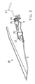
- the cutter bar 31 can be seen in a schematic representation, of which a mowing finger 32 is shown above. This is determined by a screw 33 on the cutter bar 31. There are in the plane of, or out of this, several other mowing fingers 32 the cutter bar 31 at a distance from each other assigned. The mowing fingers 32 serve to guide a cutter bar 34, which has mowing blades for separating the crop.
- the illustrated crop lift 30 corresponds to the prior art.
- the attachment of the lifter according to the invention for crop takes place on a mower just.
- the rear end 1 of the support rail 5 can be fixed for example via a screw 33 on the cutter bar 31.
- the support rail 5 is preferably made of a flat material and has flexurally elastic properties.
- the support rail 5 is supported via fastening means in the form of the receptacle 21 on the mowing finger 32.
- the receptacle 21 is connected to the support rail 5, for example by riveting.
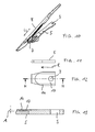
- FIG. 10 is an alternative embodiment with respect to the support rail 5 to that in FIG. 1 illustrated lift shown in perspective.
- the support rail 5 has a recess 3 in the form of a circular bore, which in relation to a slot or slotted back slot according to FIGS. 6 to 8 less expensive to produce.
- FIG. 11 shows a detail of the support rail 5 FIG. 10 in a side view.
- FIG. 12 shows the detail according to FIG. 11 in a view from above.
- the support rail 5 has in the illustrated embodiment, the in FIG. 10 shown lift, a recess 3 for attachment to the mower (not shown), wherein the recess 3 is designed as a circular bore.
- FIG. 13 is a section along the line HH in FIG. 12 shown enlarged.
- To the recess 3 around a mounting surface 17 is incorporated into the surface 14 of the support rail 5 such that by the mounting surface 17 and the surface 14 defined planes include an acute angle A, the angular extent is preferably about 1.5 degrees.
- the profile carrier 7 can be rotatably adjustable via a rotation axis. It is preferably provided that the lifter profile 8 in a plurality of spaced in its longitudinal direction L positions with the profile carrier 7 is connectable. This is the effect of Profile carrier 7 with the connection region 6 together, which also indicates the maximum adjustment range.
- the lift profile 8 is positively connected to the profile carrier 7.
- the connecting portion 6 has a shape which finds a complementary correspondence to the profile carrier 7, so that the formations can interengage accordingly and thus form a form-fitting connection in the longitudinal direction L. As a shape toothing is usually chosen. Due to the positive connection, a stable connection between the profile carrier 7 and the lifter profile 8 is advantageously produced even at low tightening forces on the profile carrier 7.
- the head portion 10 of the lift profile 8 is performed at certain crops, such as from the harvest of beans, just above the ground surface and can even penetrate the soil at short notice.
- the plastic profile 8 is elastically deformed and substantially returns to its original shape.
- the lifter profile 8 preferably has an opening 2, which extends transversely to the longitudinal direction through the lifter profile 8.
- the opening 2 extends in the longitudinal direction L between the front end 4 of the lift profile 8 and the connection region 6, in particular in a transition region between the head region 10 and the connection region 6.
- the window 2 represents a weakening of the lift profile 8 in the transition region between the head region 10 and the connection region 6, which advantageously achieves that the head region 10 is deflected to the side under strong force, whereas the connection region 6 is not significantly deformed.
- a power transmission from the head portion 10 to the connecting portion 6 takes place practically not over the weakened by the opening 2 transition region.
- the head region 10 is elastically returned to its original position after elimination of the load.
- the breakthrough 2 can be carried out continuously, which but not mandatory.
- the opening is closed by a web whose resistance to deformation is substantially lower than in the head region 10.
- FIG. 15 shows a section along the line AA in FIG. 14 , in an enlarged view.
- the section shows the lift profile 8, wherein the lift profile 8 is clamped by two oppositely acting clamping jaws 19 of a jaw assembly.
- the clamping jaws 19 have, on their side facing the connecting region 6 of the lifter profile 8, a toothing 9 which cooperates with a corresponding counter-toothing of the connecting region 6.
- the teeth 9 is given in the longitudinal direction L a predominantly based on positive connection of the components connection.
- To provide the toothing 9 directly to the jaw 19, has the advantage that it can be dispensed with the use of easily loserable items.
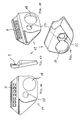
- FIGS. 16 to 19 is the jaw 19 of the lift according to FIG. 14 presented in four different views, which are described here together.
- the toothing 9 has a number of teeth on the inside of a half-shell-shaped receptacle for the connection region of the lifter profile 8 (not shown).
- the recesses 18 and 20 of the jaws 19 distinguish them from those in the FIGS. 1 to 5 and 10 shown jaws.
- the in the FIGS. 16 to 19 shown jaw 19 is provided as seen in the direction R right jaw, which on the profile carrier 7 by means of a screw bolt 23 and a nut 25 (see FIGS. 20 and 21 ) is to be fastened with the first recess 20. A screwing of the two jaws 19 against each other does not occur.
- the formation 22 around the first recess 20 around serves a rotationally positive reception of a screw head 23 ', which is usually four- or hexagonal shaped to facilitate the tightening and loosening of a lock nut 25.
- FIGS. 20 and 21 show the lifter according to the invention according to FIG. 14 in two perspective views.
- the FIG. 20 is the left in the working direction R
- the FIG. 21 the right side in the direction of R visible.
- the in the FIG. 20 Recognizable left jaw 19 also has the second recess of larger diameter than the first recess 20.
- Within the second recess 18 of the right jaw 19 fastened bolt 23 can be seen, which is secured with the nut 25.
- a loosening of the nut 25 and thus a release of the right jaw 19 is possible without the left jaw 19 to solve. Rather, it maintains the preset angle of the lift profile 8 by leaving the relative position of the left jaw 19 to the tread carrier 7 unchanged while the tread 8 is exchanged, for example due to a defect.
- the left jaw 19 is also secured by a bolt 24 through the first recess 20 on the profile carrier, wherein in the FIG. 20 only the bolt head 24 'is visible, which is positively received in the hexagonal shape 22 of the jaw 19.
- the bolt 24 is secured by a nut 26.
- the second recess 18 of the right clamping jaw 19 also recognizes a release of the left jaw 19, while the right jaw remains attached to the profile carrier 7.
- the bolt head 23 ' is positively received in the hexagonal shape 22 of the right jaw 19 to facilitate the loosening and tightening of the nut 25.
Abstract
Heber für Erntegut für ein Mähwerk einer Erntemaschine, umfassend eine an dem Mähwerk befestigbare Tragschiene 5, wobei ein Heberprofil 8 mit der Tragschiene verbunden ist, wobei die Tragschiene 5 eine Ausnehmung 3 zur Befestigung an dem Mähwerk aufweist, und wobei um die Ausnehmung 3 herum eine Anschraubfläche 17 derart in die Oberfläche 14 der Tragschiene 5 eingearbeitet ist, dass durch die Anschraubfläche und die Oberfläche definierte Ebenen einen spitzen Winkel A einschließen.A crop hoist for a mower of a harvester, comprising a support rail 5 attachable to the mower, a lift profile 8 being connected to the support rail, the support rail 5 having a recess 3 for attachment to the mower, and a recess around the recess 3 Mounting surface 17 is incorporated into the surface 14 of the support rail 5 in such a way that defined by the mounting surface and the surface levels include an acute angle A.
Description
Die Erfindung betrifft einen Heber für Erntegut für ein Mähwerk einer Erntemaschine, umfassend eine an dem Mähwerk befestigbare Tragschiene, wobei die Tragschiene einen Profilträger aufweist und wobei ein Heberprofil an dem Profilträger vorgesehen ist, oder wobei das Heberprofil mit der Tragschiene verbunden ist.The invention relates to a lift for crop for a mower of a harvester, comprising a mounting rail attachable to the mower, wherein the support rail has a profile support and wherein a lift profile is provided on the profile support, or wherein the lift profile is connected to the support rail.
Aus dem Stand der Technik ist ein sogenannter Ährenheber bekannt, welcher mit dem vorderen Teil der Tragschiene, an dem ein Halmheber befestigt ist, über den Boden gleitet oder sich knapp über dem Boden bewegt und mit dem Halmheber am Boden liegende Halme des Ernteguts aufnimmt, so dass diese durch das Messerwerk des Mähwerks abgeschnitten werden können und somit die Ähren beispielsweise einem Dreschwerk zugeführt werden können. Einen derartigen Ährenheber zeigt die
Bei Erntegut, welches die Früchte nicht an der Spitze von vergleichsweise langen Halmen trägt, wie dies bei Getreide der Fall ist, sondern an Sträuchern wächst, wie beispielsweise Hülsenfrüchte, sind die Früchte oder Schoten in dem gesamten Strauch verteilt, auch in dem bodennahen Bereich des Strauchs. Daraus ergibt sich die Forderung, derartiges Erntegut besonders knapp über dem Boden zu schneiden und durch spezielle Heber derart anzuheben, dass möglichst keine Früchte durch das Mähwerk zerstört werden. Dazu werden beispielsweise die zuvor beschriebenen Ährenheber mit der Abwandlung verwendet, dass die führende Spitze des Halmhebers so weit herabragt, dass diese idealer weise unmittelbar an der Ackeroberfläche geführt wird. Durch Steine im Boden werden die Ährenheber dabei jedoch häufig beschädigt und müssen aufwendig ausgetauscht bzw. instandgesetzt werden. Die
Eine Aufgabe der Erfindung besteht darin, einen Heber für Erntegut zur Verfügung zu stellen, welcher weniger störungsanfällig und/oder mit geringerem Aufwand instand setzbar ist.An object of the invention is to provide a lifter for crop, which is less susceptible to failure and / or with less effort repairable settable.
Die Aufgabe wird gelöst durch einen Heber für Erntegut gemäß Patentanspruch 1. In den Unteransprüchen sind bevorzugte Ausführungsformen und vorteilhafte Weiterbildungen angegeben.The object is achieved by a lifter for crop according to
Mit der Bezeichnung als Heber für Erntegut soll zum Ausdruck gebracht werden, dass keine Einschränkung auf ein spezielles Erntegut, wie Getreideähren oder Hülsenfrüchte vorgenommen wird. Die erfindungsgemäßen Heber für Erntegut sind als Heber für beliebiges Erntegut geeignet. Auf Besonderheiten in der Verarbeitung von speziellem Erntegut wird gegebenenfalls im Einzelnen eingegangen.The term "lifter for crops" is intended to express that no restriction is made to a specific crop, such as cereal ears or legumes. The lifters for crops according to the invention are suitable as lifters for any crop. Special features in the processing of special crops will be discussed in detail.
Der erfindungsgemäße Heber für Erntegut für ein Mähwerk einer Erntemaschine umfasst eine an dem Mähwerk befestigbare Tragschiene mit einen Profilträger für ein Heberprofil, in der Regel an einem in einer Arbeitsrichtung vorderen Ende der Tragschiene. Die Arbeitsrichtung entspricht in der Regel der Fahrtrichtung der Erntemaschine. Das Heberprofil ist vorzugsweise zur lösbaren Befestigung an dem Profilträger vorgesehen. Ein Vorteil dieses Hebers für Erntegut besteht darin, dass das Heberprofil einzeln von dem Profilträger lösbar und austauschbar ist. Bei einer Beschädigung kann dieser Austausch schnell und einfach durchgeführt werden. Die Ersatzteile in Form der einzelnen Profilträger sind wesentlich kleiner, leichter und kostengünstiger als vollständige, einteilige Ährenheber.The crop lift according to the invention for a mower deck of a harvesting machine comprises a mounting rail which can be fastened to the mower and has a profile carrier for a lift profile, as a rule at a front end of the carrier rail in one working direction. The working direction usually corresponds to the direction of travel of the harvester. The lift profile is preferably provided for releasable attachment to the profile carrier. An advantage of this lifter for crop is that the lifter profile is individually detachable and replaceable from the profile carrier. If damaged, this replacement can be done quickly and easily. The spare parts in the form of the individual profile beams are much smaller, lighter and more cheaper than complete, one-piece cereal lifter.
Bevorzugt ist das Heberprofil in einer Mehrzahl von in Längsrichtung des Heberprofils beabstandeten Positionen mit dem Profilträger verbindbar. Die Längsrichtung entspricht einer Haupterstreckungsrichtung des in der Regel im Wesentlichen stabförmigen oder klingenförmigen Heberprofils. Der Heber für Erntegut erlaubt vorteilhaft eine Verstellung des Heberprofils in Längsrichtung und bietet somit eine Möglichkeit, die Höhe der führenden Spitze des Heberprofils über dem Boden besonders genau einzustellen und sie mit möglichst geringem Abstand über dem Boden zu führen. Weiterhin bevorzugt ist die Verbindung in diskreten Positionen entlang des Heberprofils herstellbar und weiterhin besonders bevorzugt als formschlüssige Verbindung. Damit ist insbesondere eine formschlüssige Verbindung zwischen dem Heberprofil und dem Profilträger in Längsrichtung des Heberprofils gemeint, da in dieser Richtung die größte Kraft auf die Verbindung einwirkt. Die Einstellbarkeit in diskreten Positionen, das bedeutet in endlichen, abzählbaren Positionen, hat den Vorteil gegenüber einer stufenlosen Verstellbarkeit, dass bei einem bekannten Abstand der Positionen zueinander eine Einstellung auf ein bestimmtes Maß ohne Zuhilfenahme von Messmitteln ermöglicht wird.Preferably, the lifter profile in a plurality of spaced apart in the longitudinal direction of the lifter profile positions with the profile carrier is connectable. The longitudinal direction corresponds to a main extension direction of the usually substantially rod-shaped or blade-shaped lift profile. The lifter for crops advantageously allows an adjustment of the lifter profile in the longitudinal direction and thus offers a possibility to adjust the height of the leading tip of the lifter profile above the ground particularly accurately and to guide them with the shortest possible distance above the ground. Further preferably, the compound in discrete positions along the lift profile can be produced and further particularly preferred as a positive connection. This means in particular a positive connection between the lift profile and the profile carrier in the longitudinal direction of the lift profile, since in this direction the greatest force acts on the connection. The adjustability in discrete positions, that is to say in finite, countable positions, has the advantage over stepless adjustability that, given a known distance of the positions from one another, adjustment to a certain extent is made possible without the aid of measuring means.
Gemäß einer weiteren bevorzugten Ausführungsform ist vorgesehen, dass das Heberprofil einen Verbindungsbereich aufweist, wobei der Verbindungsbereich sich in Längsrichtung entlang des Heberprofils erstreckt und wobei Befestigungsmittel an dem Profilträger mit dem Verbindungsbereich zusammenwirken. Besonders bevorzugt weisen die Befestigungsmittel eine Klemmbackenanordnung und/oder eine Verzahnung auf. Insbesondere ist die Verzahnung an dem Profilträger, vorzugsweise an einer Klemmbacke vorgesehen. Die entsprechende Klemmbacke kann beispielsweise einteilig mit Verzahnung hergestellt sein, insbesondere als Gieß- oder Spritzgießteil. Alternativ könnte die Verzahnung an mindestens einem Einlegeteil gebildet sein, wobei mindestens eine Klemmbacke des Profilträgers ein Einlegeteil formschlüssig aufnimmt.According to a further preferred embodiment, it is provided that the lift profile has a connection region, wherein the connection region extends in the longitudinal direction along the lift profile and wherein fastening means on the profile support interact with the connection region. Particularly preferably, the fastening means on a jaw assembly and / or a toothing. In particular, the toothing on the profile carrier, preferably provided on a jaw. The corresponding clamping jaw can be produced, for example, in one piece with toothing, in particular as a casting or injection-molded part. Alternatively, the toothing could be formed on at least one insert, wherein at least one jaw of the profile carrier receives an insert form-fitting manner.
Gemäß einer weiteren bevorzugten Ausführungsform ist vorgesehen, dass das Heberprofil in dem Verbindungsbereich eine Gegenverzahnung aufweist, wobei die Gegenverzahnung mit der Verzahnung an dem Profilträger zusammenwirkt.According to a further preferred embodiment it is provided that the lift profile in the connection region has a counter-toothing, wherein the Gegenverzahnung cooperates with the toothing on the profile carrier.
Gemäß einer weiteren bevorzugten Ausführungsform ist der Profilträger über eine quer zur Arbeitsrichtung ausgerichtete Drehachse drehbeweglich verstellbar. Dadurch lässt sich vorteilhaft auch der Winkel zwischen dem Heberprofil und der Tragschiene anpassen, wodurch die Position der führenden Spitze des Heberprofils relativ zum Boden zusätzlich einstellbar ist.According to a further preferred embodiment, the profile carrier is rotatably adjustable via a rotational axis aligned transversely to the working direction. As a result, the angle between the lifter profile and the mounting rail can be advantageously adapted, whereby the position of the leading tip of the lifter profile is additionally adjustable relative to the ground.
Vorzugsweise sind die Profilträger aus einem stabilen Werkstoff hergestellt, welcher besonders gut elastisch verformbar ist ohne sich wesentlich plastisch zu verformen.Preferably, the profile carrier are made of a stable material, which is particularly well elastically deformable without significantly plastically deform.
Das Heberprofil weist bevorzugt ein in Arbeitsrichtung führendes Ende auf, wobei ein Durchbruch in dem Heberprofil zur Erleichterung einer elastischen Verformung des Heberprofils bei einer Krafteinwirkung auf das führende Ende vorgesehen ist. Der Durchbruch bewirkt ein Einknicken des Heberprofils in dem Bereich des Durchbruchs, der eine strukturelle Schwächung darstellt und eine elastische Verformung erleichtert. Trifft das führende Ende des Heberprofils im Einsatz an einem Heber für Erntegut auf beispielsweise einen Stein, der eine erhebliche Kraft auf das Heberprofil ausübt, so gibt das Heberprofil leichter nach und weicht dem Hindernis durch elastische Verformung aus, ohne dass es zu Schäden an dem Heber für Erntegut kommt. Anschließend federt das Heberprofil zurück in seine ursprüngliche Form. Besonders vorteilhaft ist das Heberprofil dort einsetzbar, wo das führende Ende des Heberprofils besonders tief geführt wird, beispielsweise unmittelbar oberhalb der Bodenoberfläche, wie dies besonders bei der Ernte von Hülsenfrüchten, beispielsweise Bohnen, insbesondere Sojabohnen der Fall ist.The lift profile preferably has a leading end in the direction of work, wherein a breakthrough in the lift profile to facilitate elastic deformation of the lift profile is provided upon application of force to the leading end. The breakthrough causes a buckling of the lift profile in the area of the opening, which represents a structural weakening and facilitates elastic deformation. When the leading end of the lifter profile encounters, for example, a rock that exerts a considerable force on the lifter profile in use on a crop lift, the lifter profile gives way more easily and evades the obstacle by elastic deformation, without causing any damage to the lifter comes for crops. Then the lift profile springs back to its original shape. Particularly advantageously, the lifter profile can be used where the leading end of the lifter profile is guided particularly deep, for example, immediately above the soil surface, as is the case especially for the harvest of legumes, such as beans, especially soybeans.
Gemäß einer bevorzugten Ausführungsform ist vorgesehen, dass der Durchbruch zumindest abschnittsweise zwischen dem führenden Ende und einem Verbindungsbereich zur Befestigung an einem Profilträger angeordnet ist. Vorzugsweise weist der Durchbruch eine Haupterstreckungsrichtung entlang einer Längsrichtung des Heberprofils auf. Der Durchbruch ist insbesondere in Längsrichtung mindestens doppelt so lang, wie quer zu der Längsrichtung. Besonders bevorzugt läuft der Durchbruch an seinen Enden in Längsrichtung unter spitzem Winkel zu. Weiterhin bevorzugt ist der Durchbruch von einem Steg verschlossen, wobei der Steg einer Deformierung des Durchbruchs keinen wesentlichen Widerstand entgegensetzt.According to a preferred embodiment, it is provided that the opening is arranged at least in sections between the leading end and a connection region for attachment to a profile carrier. Preferably, the aperture has a main extension direction along a longitudinal direction of the lift profile. The breakthrough is at least twice as long, in particular in the longitudinal direction, as transverse to the longitudinal direction. Particularly preferably, the breakthrough runs at its ends in the longitudinal direction at an acute angle. Farther Preferably, the opening is closed by a web, wherein the web of a deformation of the opening opposes no significant resistance.
Gegenstand der Erfindung, der die Aufgabe löst, ist ein Heber für Erntegut für ein Mähwerk einer Erntemaschine, umfassend eine an dem Mähwerk befestigbare Tragschiene, wobei ein Heberprofil mit der Tragschiene verbunden ist, wobei die Tragschiene eine Ausnehmung zur Befestigung an dem Mähwerk aufweist, und wobei um die Ausnehmung herum eine Anschraubfläche derart in die Oberfläche der Tragschiene eingearbeitet ist, dass durch die Anschraubfläche und die Oberfläche definierte Ebenen einen spitzen Winkel einschließen. Als Anschraubfläche ist diejenige Fläche zu verstehen, auf welche der Kopf eines Gewindebolzens bzw. eine Gewindemutter beim Festziehen einer Schraubverbindung wirkt. Die entsprechenden Flächen an dem Kopf oder der Mutter sind parallel zu der Oberfläche der Tragschiene ausgerichtet und somit um den spitzen Winkel zu der Anschraubfläche gekippt. Es kommt zu einer Verspannung der Schraubverbindung, was die Festigkeit der Schraubverbindung nicht beeinträchtigt. Vorteilhaft wird dadurch eine Verlustsicherung für den gesamten Heber für Erntegut geschaffen. Bei einem selbsttätigen Lösen der Schraubverbindung kann sich der Heber in Arbeitsrichtung gesehen nach vorne verschieben, wodurch die Schraubverbindung vorteilhaft erneut verspannt wird, da die Anschraubfläche sich keilartig unter die Gewindemutter bzw. den Schraubenkopf schiebt. Ein weiterer Vorteil für die Handhabung des Hebers besteht darin, dass keine Sicherungsmaßnahmen zur Sicherung der Schraubverbindung vorgenommen werden müssen, welche im Falle eines durch Beschädigung notwendigen Austausches des Hebers aufwändig geöffnet werden müssten. Durch die abgeschrägte Anschraubfläche kann eine einfach zu lösende Schraubverbindung verwendet werden. Vorzugsweise weist der spitze Winkel ein Winkelmaß von weniger als 5 Grad auf, vorzugsweise von weniger als 3 Grad und besonders bevorzugt von etwa 1,5 Grad. Winkel von weniger als 0,5 Grad sind eher zu flach, als dass der erfindungsgemäße technische Effekt erzielt werden könnte.The object of the invention, which solves the problem, is a lifter for crop for a mower of a harvester comprising a mounting rail attachable to the mower, wherein a lifter profile is connected to the mounting rail, wherein the mounting rail has a recess for attachment to the mower, and wherein a mounting surface is incorporated into the surface of the mounting rail around the recess such that planes defined by the mounting surface and the surface form an acute angle. An attachment surface is that surface on which the head of a threaded bolt or a threaded nut acts when tightening a screw connection. The corresponding surfaces on the head or nut are aligned parallel to the surface of the mounting rail and thus tilted at the acute angle to the mounting surface. It comes to a tension of the screw, which does not affect the strength of the screw. This advantageously creates a loss protection for the entire lifter for crops. In an automatic loosening of the screw, the lifter seen in the working direction can move forward, whereby the screw is advantageously clamped again because the mounting surface pushes like a wedge under the nut or the screw head. Another advantage for the handling of the lift is that no security measures to secure the screw must be made, which would have to be opened consuming in the event of a necessary replacement of the lift by damage. Due to the tapered mounting surface, an easy-to-loosen screw connection can be used. Preferably, the acute angle has an angular extent of less than 5 degrees, preferably less than 3 degrees and most preferably about 1.5 degrees. Angles of less than 0.5 degrees are rather too shallow to allow the inventive technical effect to be achieved.
Gemäß einer bevorzugten Ausführungsform ist die Ausnehmung als ein sich in Arbeitsrichtung erstreckendes Langloch ausgeführt und/oder die Ausnehmung ist zu einem in Arbeitsrichtung hinteren Ende der Tragschiene hin geöffnet. Dadurch ist besonders vorteilhaft eine Demontage und Montage des erfindungsgemäßen Hebers ohne ein vollständiges Herausdrehen des Bolzens aus der Mutter möglich. Weiterhin bevorzugt weist die Tragschiene eine Aufnahme für einen Mähfinger an dem Mähwerk der Erntemaschine auf. Mit dieser Aufnahme wird der Heber auf den in Arbeitsrichtung nach vorn weisenden Mähfinger aufgeschoben. Der Heber für Erntegut gemäß dem zuletzt beschriebenen Erfindungsgegenstand kann, ebenso wie die zuvor beschriebenen Gegenstände, ein abnehmbares Heberprofil aufweisen. Ebenso sollen aber auch einteilige Heber für Erntegut umfasst sein, bei denen das Heberprofil fest mit der Tragschiene verbunden ist.According to a preferred embodiment, the recess is designed as a slot extending in the working direction and / or the recess is open towards a rear end of the mounting rail in the working direction. This is particularly advantageous disassembly and assembly of the lifter according to the invention without a complete unscrewing of the bolt from the mother possible. Further preferably, the support rail on a receptacle for a mowing finger on the mower of the harvester. With this recording, the lifter is pushed onto the mowing finger pointing forward in the working direction. The crop lift according to the last described subject invention may, as well as the previously described articles, have a removable lift profile. Likewise, however, should also include one-piece lift for crop, in which the lift profile is firmly connected to the support rail.
Bevorzugt ist ein Heberprofil zur lösbaren Befestigung an dem Profilträger durch eine Klemmbackenanordnung mit zwei Klemmbacken vorgesehen. Vorzugsweise handelt es sich bei dem Heber um eine Ausführungsform des eingangs beschriebenen Hebers.Preferably, a lifter profile for releasable attachment to the profile carrier is provided by a jaw assembly with two jaws. Preferably, the lift is an embodiment of the lift described above.
Bevorzugt ist mindestens eine der zwei Klemmbacken lösbar, während die andere der zwei Klemmbacken an dem Profilträger festgelegt bleibt. Dadurch lässt sich besonders vorteilhaft ein defektes Heberprofil auswechseln oder in Längsrichtung L verstellen, ohne dass der eingestellte Winkel für das Heberprofil verloren geht. Da die zweite Klemmbacke an dem Profilträger befestigt bleibt, kann die gelöst Klemmbacke einfach auf dieselbe Winkelposition eingestellt werden, wie die feste Klemmbacke und das neue Heberprofil ist exakt ausgerichtet. Angesichts der nicht unerheblichen Anzahl von Wechseln defekter Heberprofile pro Erntesaison stellt der Entfall der Ausrichtung des Winkels eine Arbeitserleichterung und Zeitersparnis dar.Preferably, at least one of the two jaws is releasably, while the other of the two jaws remains fixed to the profile carrier. This makes it particularly advantageous to replace a defective lift profile or adjust in the longitudinal direction L without the set angle for the lift profile is lost. Since the second jaw remains attached to the profile support, the loosened jaw can be easily adjusted to the same angular position as the fixed jaw and the new lift profile is exactly aligned. In view of the not inconsiderable number of changes of defective lift profiles per crop season, the elimination of the orientation of the angle represents a reduction in work and time.
Gemäß einer bevorzugten Ausführungsform ist vorgesehen, dass die Klemmbacken jeweils mit einem separaten Befestigungsmittel an dem Profilträger befestigt sind. Somit ist es gleichgültig, welche Klemmbacke gelöst wird. Die jeweils andere bleibt fest verbunden mit dem Profilträger. Insbesondere weisen die Klemmbacken jeweils eine erste Ausnehmung zur befestigenden Aufnahme eines Schraubbolzens und eine zweite Ausnehmung als Zugang zu einem Schraubbolzen der jeweils anderen Klemmbacke auf. Die zweite Ausnehmung ermöglicht vorteilhaft, den Schraubbolzen der jeweils anderen Klemmbacke mit einem Gegenelement, also beispielsweise einer Schraubmutter an dem Profilträger zu sichern. Das bedeutet, die ersten Aufnahmen weisen jeweils eine kleinere Bohrung auf, als die zweiten Aufnahmen, so dass eine Befestigung nur mit den ersten Aufnahmen möglich ist. Die ersten Aufnahmen können vorzugsweise eine Ausformung entsprechend der Kopfform des Schraubbolzenkopfs entsprechen, um das Anziehen der Schraubmutter zu erleichtern.According to a preferred embodiment, it is provided that the clamping jaws are each fastened to the profile carrier with a separate fastening means. Thus, it does not matter which jaw is solved. The other one remains firmly connected to the profile carrier. In particular, the jaws each have a first recess for fastening receiving a bolt and a second recess as access to a bolt of the other jaw on. The second recess advantageously allows the bolt of each other jaw with a counter element, so for example a nut to secure the profile support. This means that the first recordings each have a smaller bore than the second recordings, so that attachment only with the first recordings is possible. The first receptacles may preferably correspond to a shape corresponding to the head shape of the bolt head to facilitate the tightening of the nut.
Alle hierin beschriebenen Erfindungsgegenstände sind beliebig miteinander kombinierbar. Bevorzugte Ausführungsbeispiele werden nachfolgend mit Bezugnahme auf die Zeichnungen dargestellt.All of the subject matter described herein may be combined with one another as desired. Preferred embodiments will now be described with reference to the drawings.
Hierin zeigen:
-
Figur 1 -
Figur 2Figur 1 in einer Seitenansicht; -
Figur 3Figur 1 in einer Ansicht von oben auf das Heberprofil; -
Figur 4Figur 2 ; -
Figur 5Figur 2 ; -
Figur 6G nach Figur 2 ; -
Figur 7Details gemäß Figur 6 ; -
Figur 8Figur 7 ; -
Figur 9 -
Figur 10 -
Figur 11Details entsprechend Figur 6 , jedoch in der Ausführungsform desHebers gemäß Figur 10 ; -
Figur 12Details gemäß Figur 11 ; -
Figur 13 einen Schnitt längs der Linie H-H nachFigur 12 ; -
Figur 14 -
Figur 15der Figur 14 ; -
Figuren 16 verschiedene Ansichten einer Klemmbacke einer Ausführungsform des Hebers gemäß derbis 19Figur 14 ; -
Figuren 20 und 21Figur 14 in zwei perspektivischen Ansichten.
-
FIG. 1 a perspective view of an embodiment of a lifter according to the invention for crops; -
FIG. 2 the lifter for harvested cropsFIG. 1 in a side view; -
FIG. 3 the lifter for harvested cropsFIG. 1 in a view from above on the lift profile; -
FIG. 4 a cross section along the line AA afterFIG. 2 ; -
FIG. 5 a section along the line JJ afterFIG. 2 ; -
FIG. 6 a side view of the detail G afterFIG. 2 ; -
FIG. 7 a top view of the detail according toFIG. 6 ; -
FIG. 8 a section along the line HH afterFIG. 7 ; -
FIG. 9 a side view of a one-piece embodiment of the crop lift, set on a mower blade and mowing fingers of a harvester; -
FIG. 10 a perspective view of another embodiment of a lifter according to the invention for crops; -
FIG. 11 a side view of a detail accordinglyFIG. 6 but in the embodiment of the lifter according toFIG. 10 ; -
FIG. 12 a top view of the detail according toFIG. 11 ; -
FIG. 13 a section along the line HH afterFIG. 12 ; -
FIG. 14 a side view of another embodiment of a lifter according to the invention for crops; -
FIG. 15 a section along the line AA in theFIG. 14 ; -
FIGS. 16 to 19 various views of a jaw of an embodiment of the lifter according to theFIG. 14 ; -
FIGS. 20 and 21 the lifter according to the inventionFIG. 14 in two perspective views.
In der
An ihrem vorderen Ende weist die Tragschiene 5 einen Profilträger 7 auf, an dem ein Heberprofil 8 zur lösbaren Befestigung vorgesehen ist. Das Heberprofil 8 ist bevorzugt in einer Mehrzahl von in Längsrichtung L des Heberprofils 8 beabstandeten Positionen mit dem Profilträger 7 verbindbar. Dazu weist der Profilträger 7 im dargestellten Ausführungsbeispiel zwei gegeneinander verspannbare Klemmbacken 19 auf, welche auf einen Verbindungsbereich 6 des Heberprofils 8 einwirken. Das Heberprofil 8 an sich ist ein in der durch den Doppelpfeil L gekennzeichneten Längsrichtung langgestrecktes, in etwa stabförmiges Bauteil mit einem Kopfbereich 10 an seinem führenden Ende 4, welcher dazu vorgesehen ist, möglichst knapp über dem Boden geführt zu werden. Der Kopfbereich 10 kann beispielsweise in etwa pfeilartig geformt sein, von der Spitze am führenden Ende 4 aus nach hinten breiter werdend, während ein mittlerer Abschnitt des Heberprofils 8 mit dem Verbindungsbereich 6 einen im wesentlichen gleichbleibenden Querschnitt aufweist und ein Ende 12 des Heberprofils 8 nach hinten leicht schmaler werdend zusammenläuft. Auf die Ausgestaltung des Verbindungsbereichs 6 und eines Durchbruchs 2 des Heberprofils 8 wird nachfolgend mit Bezug auf weitere Figuren eingegangen.At its front end, the
In den
Der Kopfbereich 10 des Heberprofils 8 wird bei bestimmtem Erntegut, wie beispielsweise von der Ernte von Bohnen, äußerst knapp über der Bodenoberfläche geführt und kann dabei sogar kurzfristig in den Boden eindringen, wodurch verhindert werden soll, dass weit unten am Strauch wachsende Schoten durch das Mähwerk zerstört werden. Das Heberprofil 8 ist dabei besonders starken Belastungen ausgesetzt, weshalb der Verschleiß an den Heberprofilen 8 vergleichsweise hoch ist. Es hat sich als vorteilhaft herausgestellt, die Heberprofile 8 aus einem Material herzustellen, das vergleichsweise günstig in der Herstellung, aber widerstandsfähig und insbesondere gut elastisch verformbar ist. Wenn der Kopfbereich 10 beispielsweise auf Steine im Boden trifft, wird das Kunststoffprofil 8 elastisch deformiert und kehrt im Wesentlichen in seine ursprüngliche Form zurück. Zur Unterstützung der elastischen Deformierbarkeit des Kopfbereiches 10 weist das Heberprofil 8 bevorzugt einen Durchbruch 2 auf, welcher quer zu der Längs- bzw. Arbeitsrichtung durch das Heberprofil 8 hindurch verläuft. Der Durchbruch 2 erstreckt sich in Längsrichtung L zwischen dem vorderen Ende 4 des Heberprofils 8 und dem Verbindungsbereich 6, insbesondere in einem Übergangsbereich zwischen dem Kopfbereich 10 und dem Verbindungsbereich 6. Da in dem Verbindungsbereich 6 der Profilträger 7 das Heberprofil 8 hält, ist anzustreben, dass der Verbindungsbereich 6 nicht deformiert wird, da sonst die formschlüssige Verbindung mit dem Profilträger 7 gelöst werden könnte, was zu einem Verlust des Heberprofils 8 während des Ernteeinsatzes zur Folge haben könnte. Das Fenster 2 stellt eine Schwächung des Heberprofils 8 in dem Übergangsbereich zwischen dem Kopfbereich 10 und dem Verbindungsbereich 6 dar, wodurch vorteilhaft erreicht wird, dass der Kopfbereich 10 unter starker Krafteinwirkung zur Seite ausgelenkt wird, wogegen der Verbindungsbereich 6 nicht wesentlich verformt wird. Eine Kraftübertragung vom Kopfbereich 10 zu dem Verbindungsbereich 6 findet über den durch den Durchbruch 2 geschwächten Übergangsbereich praktisch nicht statt. Insbesondere wird der Kopfbereich 10 nach Wegfall der Belastung elastisch wieder in seine ursprüngliche Position zurückgestellt. Der Durchbruch 2 kann dabei durchgehend ausgeführt sein, was jedoch nicht zwingend erforderlich ist. Gemäß einer bevorzugten Ausführungsform ist der Durchbruch 2 durch einen Steg 16 verschlossen, dessen Widerstand gegenüber Verformung wesentlich geringer ist, als bei dem Kopfbereich 10. Ein Vorteil des geschlossenen Durchbruchs besteht darin, dass sich keine Halme oder Ähnliches in dem Durchbruch verfangen können, die das Mähergebnis beeinflussen könnten.The
Im Zusammenhang mit den
Anhand der
In der
In der
Anhand der
In der
Der Kopfbereich 10 des Heberprofils 8 wird bei bestimmtem Erntegut, wie beispielsweise von der Ernte von Bohnen, äußerst knapp über der Bodenoberfläche geführt und kann dabei sogar kurzfristig in den Boden eindringen. Wenn der Kopfbereich 10 beispielsweise auf Steine im Boden trifft, wird das Kunststoffprofil 8 elastisch deformiert und kehrt im Wesentlichen in seine ursprüngliche Form zurück. Zur Unterstützung der elastischen Deformierbarkeit des Kopfbereiches 10 weist das Heberprofil 8 bevorzugt einen Durchbruch 2 auf, welcher quer zu der Längsrichtung durch das Heberprofil 8 hindurch verläuft. Der Durchbruch 2 erstreckt sich in Längsrichtung L zwischen dem vorderen Ende 4 des Heberprofils 8 und dem Verbindungsbereich 6, insbesondere in einem Übergangsbereich zwischen dem Kopfbereich 10 und dem Verbindungsbereich 6. Da in dem Verbindungsbereich 6 der Profilträger 7 das Heberprofil 8 hält, ist anzustreben, dass der Verbindungsbereich 6 nicht deformiert wird, da sonst die formschlüssige Verbindung mit dem Profilträger 7 gelöst werden könnte, was zu einem Verlust des Heberprofils 8 während des Ernteeinsatzes zur Folge haben könnte. Das Fenster 2 stellt eine Schwächung des Heberprofils 8 in dem Übergangsbereich zwischen dem Kopfbereich 10 und dem Verbindungsbereich 6 dar, wodurch vorteilhaft erreicht wird, dass der Kopfbereich 10 unter starker Krafteinwirkung zur Seite ausgelenkt wird, wogegen der Verbindungsbereich 6 nicht wesentlich verformt wird. Eine Kraftübertragung vom Kopfbereich 10 zu dem Verbindungsbereich 6 findet über den durch den Durchbruch 2 geschwächten Übergangsbereich praktisch nicht statt. Insbesondere wird der Kopfbereich 10 nach Wegfall der Belastung elastisch wieder in seine ursprüngliche Position zurückgestellt. Der Durchbruch 2 kann dabei durchgehend ausgeführt sein, was jedoch nicht zwingend erforderlich ist. Gemäß einer bevorzugten Ausführungsform ist der Durchbruch durch einen Steg verschlossen, dessen Widerstand gegenüber Verformung wesentlich geringer ist, als bei dem Kopfbereich 10.The
Im Zusammenhang mit der
In den
Die
- 11
- Hinteres EndeRear end
- 22
- Durchbruchbreakthrough
- 33
- Ausnehmungrecess
- 44
- Führendes EndeLeading end
- 55
- Tragschienerail
- 66
- Verbindungsbereichconnecting area
- 77
- Profilträgerprofile support
- 88th
- HeberprofilHeber profile
- 99
- Verzahnunggearing
- 1010
- Kopfbereichhead area
- 1111
- Einlegeteilinsert
- 1212
- EndeThe End
- 1414
- Oberfläche der TragschieneSurface of the mounting rail
- 1515
- KlemmbackenanordnungJaw assembly
- 1616
- Stegweb
- 1717
- Anschraubflächebolting
- 1818
- Zweite Ausnehmung der KlemmbackeSecond recess of the jaw
- 1919
- Klemmbackejaw
- 2020
- Erste Ausnehmung der KlemmbackeFirst recess of the jaw
- 2121
- Aufnahmeadmission
- 2222
- Ausformungformation
- 2323
- Schraubbolzenbolts
- 23'23 '
- Schraubbolzenkopfbolt head
- 2424
- Schraubbolzenbolts
- 24'24 '
- Schraubbolzenkopfbolt head
- 2525
- Schraubmutternut
- 2626
- Schraubmutternut
- 3030
- Heber für Erntegut nach dem Stand der TechnikLifter for crop according to the prior art
- 3131
- MähbalkenCutting Bar
- 3232
- Mähfingermowing finger
- 3333
- Schraubescrew
- 3434
- Messerbalkencutter bar
- LL
- Längsrichtunglongitudinal direction
- RR
- Arbeitsrichtungworking direction
- AA
- Winkelangle
Claims (4)
dadurch gekennzeichnet,
dass die Tragschiene (5) eine Ausnehmung (3) zur Befestigung an dem Mähwerk aufweist, wobei um die Ausnehmung (3) herum eine Anschraubfläche (17) derart in die Oberfläche (14) der Tragschiene (5) eingearbeitet ist, dass durch die Anschraubfläche und die Oberfläche definierte Ebenen einen spitzen Winkel (A) einschließen.A crop lift for a mower of a harvester, comprising a support rail (5) attachable to the mower, a lift profile (8) being connected to the support rail,
characterized,
in that the mounting rail (5) has a recess (3) for attachment to the mower, a mounting surface (17) being machined around the recess (3) in the surface (14) of the mounting rail (5) in such a way that the mounting surface and the surface defined planes include an acute angle (A).
dadurch gekennzeichnet,
dass die Ausnehmung (3) als ein sich in einer Arbeitsrichtung (R) erstreckendes Langloch ausgeführt ist und/oder dass die Ausnehmung (3) zu einem in Arbeitsrichtung (R) hinteren Ende (1) der Tragschiene (5) hin geöffnet ist.Catcher for crop according to claim 1,
characterized,
that the recess (3) is designed as a in a working direction (R) extending elongated hole and / or that the recess (3) to an in working direction (R) rear end (1) of the supporting rail (5) is open towards.
dadurch gekennzeichnet,
dass der spitze Winkel (A) ein Winkelmaß von weniger als fünf Grad aufweist, vorzugsweise von weniger als drei Grad und besonders bevorzugt von etwa 1,5 Grad.Catcher for crop according to claim 2,
characterized,
that the acute angle (A) an angular dimension of less than five degrees has, preferably less than three degrees, and most preferably from about 1.5 degrees.
dadurch gekennzeichnet,
dass die Tragschiene eine Aufnahme (21) für einen Mähfinger an dem Mähwerk der Erntemaschine aufweist.A crop lift according to any one of claims 1 to 3,
characterized,
that the support rail has a receptacle (21) for a mowing finger on the deck of the harvester.
Applications Claiming Priority (2)
| Application Number | Priority Date | Filing Date | Title |
|---|---|---|---|
| DE102012100302A DE102012100302A1 (en) | 2012-01-13 | 2012-01-13 | Lift for crop |
| EP12199207.7A EP2614700B1 (en) | 2012-01-13 | 2012-12-21 | Lifter for crops |
Related Parent Applications (2)
| Application Number | Title | Priority Date | Filing Date |
|---|---|---|---|
| EP12199207.7A Division-Into EP2614700B1 (en) | 2012-01-13 | 2012-12-21 | Lifter for crops |
| EP12199207.7A Division EP2614700B1 (en) | 2012-01-13 | 2012-12-21 | Lifter for crops |
Publications (2)
| Publication Number | Publication Date |
|---|---|
| EP2805601A1 true EP2805601A1 (en) | 2014-11-26 |
| EP2805601B1 EP2805601B1 (en) | 2018-06-27 |
Family
ID=47561216
Family Applications (3)
| Application Number | Title | Priority Date | Filing Date |
|---|---|---|---|
| EP14177260.8A Active EP2805600B1 (en) | 2012-01-13 | 2012-12-21 | Lifter for crops |
| EP14177263.2A Active EP2805601B1 (en) | 2012-01-13 | 2012-12-21 | Lifter for crops |
| EP12199207.7A Active EP2614700B1 (en) | 2012-01-13 | 2012-12-21 | Lifter for crops |
Family Applications Before (1)
| Application Number | Title | Priority Date | Filing Date |
|---|---|---|---|
| EP14177260.8A Active EP2805600B1 (en) | 2012-01-13 | 2012-12-21 | Lifter for crops |
Family Applications After (1)
| Application Number | Title | Priority Date | Filing Date |
|---|---|---|---|
| EP12199207.7A Active EP2614700B1 (en) | 2012-01-13 | 2012-12-21 | Lifter for crops |
Country Status (11)
| Country | Link |
|---|---|
| US (1) | US9220199B2 (en) |
| EP (3) | EP2805600B1 (en) |
| AR (1) | AR089499A1 (en) |
| AU (1) | AU2013200189B2 (en) |
| BR (1) | BR102013000808B1 (en) |
| CA (3) | CA2801481C (en) |
| DE (1) | DE102012100302A1 (en) |
| ES (3) | ES2677819T3 (en) |
| HU (3) | HUE036871T2 (en) |
| RU (1) | RU2528712C2 (en) |
| TR (1) | TR201810006T4 (en) |
Families Citing this family (3)
| Publication number | Priority date | Publication date | Assignee | Title |
|---|---|---|---|---|
| CA2748754C (en) * | 2011-08-11 | 2017-11-07 | Dave Dietrich | High rise crop lifter |
| DE102015101983A1 (en) * | 2015-02-11 | 2016-08-11 | Claas Saulgau Gmbh | Insertion element for a maize header of a forage harvester and maize header |
| US10299437B2 (en) | 2017-07-17 | 2019-05-28 | Cnh Industrial America Llc | Header for an agricultural vehicle with deformable supports |
Citations (5)
| Publication number | Priority date | Publication date | Assignee | Title |
|---|---|---|---|---|
| DE864637C (en) * | 1950-07-13 | 1953-01-26 | Hermann Hege | AElifter |
| US2734332A (en) * | 1956-02-14 | fisher | ||
| DE1482880A1 (en) * | 1965-09-07 | 1969-10-02 | Gustav Schumacher | AEpipe lifter for combine harvester and tie mower |
| DE2325916A1 (en) | 1973-05-22 | 1974-12-12 | Schumacher | ELEVATOR FOR A GRAIN MOWER |
| WO2006072158A1 (en) | 2005-01-06 | 2006-07-13 | Dave Dietrich | Crop lifter and crop accessory attachment |
Family Cites Families (16)
| Publication number | Priority date | Publication date | Assignee | Title |
|---|---|---|---|---|
| US2734322A (en) * | 1956-02-14 | Vaughan | ||
| DE320550C (en) * | 1912-11-20 | 1920-04-23 | Lucien Bouchet | Fastening device for the lifting device of grain mowers |
| US1123632A (en) | 1913-05-06 | 1915-01-05 | John Weisgarber | Grain-lifter. |
| US1202084A (en) | 1916-01-31 | 1916-10-24 | Charles E Merkel | Lifting-guard for harvesters. |
| US1797682A (en) | 1929-06-12 | 1931-03-24 | Gaterman William | Grain-lifter guard for mowing machines |
| US2099471A (en) * | 1937-03-05 | 1937-11-16 | Cheney Weeder Company | Harvester attachment |
| US2294646A (en) * | 1940-09-19 | 1942-09-01 | Young Edward Henry | Down-grain guard for combines |
| US2484704A (en) * | 1944-03-31 | 1949-10-11 | Phillip Hyman | Pickup assembly |
| US2892298A (en) * | 1957-08-05 | 1959-06-30 | Earl J Chaney | Pickup device |
| DE1507366C3 (en) * | 1965-09-07 | 1974-03-14 | Gustav 5231 Eichelhardt Schumacher Ii | Crop lifter for grain mowers |
| DE3300769A1 (en) | 1983-01-12 | 1984-07-12 | Gustav Schumacher Ii | Grain lifter for cutter bar mowing machines or harvesting machines |
| SU1440413A1 (en) * | 1986-12-19 | 1988-11-30 | Украинский научно-исследовательский институт механизации и электрификации сельского хозяйства | Grain lifter for harvesting machine |
| FR2618975B1 (en) * | 1987-08-04 | 1991-06-07 | Bouin Gerard | TANGENTIAL POURED HARVESTING DEVICE WITH VARIABLE GEOMETRY |
| EP1061791B1 (en) * | 1998-03-10 | 2002-05-15 | Gustav Schumacher | Ear lifter |
| DE10113107B4 (en) * | 2001-03-15 | 2010-01-21 | Gebr. Schumacher Gerätebaugesellschaft mbH | Crop lifter for harvesting machine mowing systems |
| DE10123248C1 (en) * | 2001-05-12 | 2002-09-19 | Schumacher Gmbh Geb | Crop cutting implement ear lifting machine has beam with flexible rail to carry stalk lifter having mountings for cutting fingers |
-
2012
- 2012-01-13 DE DE102012100302A patent/DE102012100302A1/en not_active Ceased
- 2012-12-21 ES ES12199207.7T patent/ES2677819T3/en active Active
- 2012-12-21 EP EP14177260.8A patent/EP2805600B1/en active Active
- 2012-12-21 EP EP14177263.2A patent/EP2805601B1/en active Active
- 2012-12-21 ES ES14177263.2T patent/ES2683205T3/en active Active
- 2012-12-21 HU HUE14177260A patent/HUE036871T2/en unknown
- 2012-12-21 EP EP12199207.7A patent/EP2614700B1/en active Active
- 2012-12-21 ES ES14177260.8T patent/ES2667810T3/en active Active
- 2012-12-21 HU HUE14177263A patent/HUE040533T2/en unknown
- 2012-12-21 HU HUE12199207A patent/HUE039025T2/en unknown
- 2012-12-21 TR TR2018/10006T patent/TR201810006T4/en unknown
- 2012-12-27 AR ARP120105021A patent/AR089499A1/en active IP Right Grant
-
2013
- 2013-01-09 CA CA2801481A patent/CA2801481C/en active Active
- 2013-01-09 CA CA2892196A patent/CA2892196C/en active Active
- 2013-01-09 CA CA2892075A patent/CA2892075C/en active Active
- 2013-01-10 RU RU2013100990/13A patent/RU2528712C2/en active
- 2013-01-11 US US13/739,281 patent/US9220199B2/en active Active
- 2013-01-11 BR BR102013000808-7A patent/BR102013000808B1/en active IP Right Grant
- 2013-01-11 AU AU2013200189A patent/AU2013200189B2/en not_active Ceased
Patent Citations (5)
| Publication number | Priority date | Publication date | Assignee | Title |
|---|---|---|---|---|
| US2734332A (en) * | 1956-02-14 | fisher | ||
| DE864637C (en) * | 1950-07-13 | 1953-01-26 | Hermann Hege | AElifter |
| DE1482880A1 (en) * | 1965-09-07 | 1969-10-02 | Gustav Schumacher | AEpipe lifter for combine harvester and tie mower |
| DE2325916A1 (en) | 1973-05-22 | 1974-12-12 | Schumacher | ELEVATOR FOR A GRAIN MOWER |
| WO2006072158A1 (en) | 2005-01-06 | 2006-07-13 | Dave Dietrich | Crop lifter and crop accessory attachment |
Also Published As
| Publication number | Publication date |
|---|---|
| HUE039025T2 (en) | 2018-12-28 |
| HUE036871T2 (en) | 2018-08-28 |
| ES2677819T3 (en) | 2018-08-07 |
| BR102013000808A2 (en) | 2017-05-02 |
| CA2801481A1 (en) | 2013-07-13 |
| AR089499A1 (en) | 2014-08-27 |
| ES2683205T3 (en) | 2018-09-25 |
| AU2013200189A1 (en) | 2013-08-01 |
| TR201810006T4 (en) | 2018-08-27 |
| BR102013000808A8 (en) | 2018-03-06 |
| RU2528712C2 (en) | 2014-09-20 |
| DE102012100302A1 (en) | 2013-07-18 |
| CA2801481C (en) | 2016-09-06 |
| BR102013000808B1 (en) | 2019-08-06 |
| RU2013100990A (en) | 2014-07-20 |
| ES2667810T3 (en) | 2018-05-14 |
| CA2892075A1 (en) | 2013-07-13 |
| CA2892075C (en) | 2017-11-28 |
| HUE040533T2 (en) | 2019-03-28 |
| CA2892196C (en) | 2017-02-07 |
| EP2614700B1 (en) | 2018-04-25 |
| AU2013200189B2 (en) | 2014-09-18 |
| CA2892196A1 (en) | 2013-07-13 |
| EP2614700A3 (en) | 2013-09-04 |
| EP2805600B1 (en) | 2018-02-14 |
| US9220199B2 (en) | 2015-12-29 |
| US20130180226A1 (en) | 2013-07-18 |
| EP2614700A2 (en) | 2013-07-17 |
| EP2805600A1 (en) | 2014-11-26 |
| EP2805601B1 (en) | 2018-06-27 |
Similar Documents
| Publication | Publication Date | Title |
|---|---|---|
| EP0073359B1 (en) | Locking device for a mowing machine | |
| DD226747A5 (en) | SERIES ESTABLISHMENT DEVICE FOR A REFILLING MACHINE | |
| EP1029436B1 (en) | Fixture, mower and vehicle respectively work implement | |
| DE102007007985B4 (en) | Cutting unit for cutting stalky clippings | |
| EP1584226A2 (en) | Cutting device for/at agricultural harvesters | |
| DE10128101B4 (en) | Grainlifter | |
| EP2614700B1 (en) | Lifter for crops | |
| DE102013011088B4 (en) | Knife for a forage harvester and eccentric tool for position adjustment | |
| AT392388B (en) | GROUND MILLING | |
| DE102008045132A1 (en) | Seeder arrangement for use in multi-row sowing machine, has depth control wheels laterally and offsetly arranged adjacent to insertion blades behind each other so that circumferences of blades and wheels cut each other | |
| DE3726967C2 (en) | Harvester for harvesting corn or other cereals | |
| DE2855234A1 (en) | MAEHFINGER FOR FINGERBALKENMEWERKE | |
| EP3226673A1 (en) | Beam adjusting mechanism for a soil-working tool | |
| EP3354126B1 (en) | Cutter and shredding drum for a chaff cutter | |
| EP3653042A1 (en) | Pivoting sawing device for cutting plants | |
| DE202005007424U1 (en) | Mower bar for disc mowers | |
| DE3617003A1 (en) | Cutting device for stalk and leaf material | |
| EP1769663A1 (en) | Cutting adapter for motor scythe | |
| EP3235358A1 (en) | Plough point for use in a metering system for soil cultivation | |
| DE102009039670B9 (en) | Grainlifter | |
| DE202015104423U1 (en) | Knife set and mowing unit with a variety of knife sets | |
| DE3119938A1 (en) | Mower for combine harvesters | |
| DE2945960A1 (en) | Mower beam finger assembly - has upper portion extending rearwards to beam and supported from it | |
| DE102010017656B4 (en) | Device for cutting and cutting cuttings | |
| EP3571905B1 (en) | Coulter and tip for use in a coulter system for soil cultivation |
Legal Events
| Date | Code | Title | Description |
|---|---|---|---|
| PUAI | Public reference made under article 153(3) epc to a published international application that has entered the european phase |
Free format text: ORIGINAL CODE: 0009012 |
|
| 17P | Request for examination filed |
Effective date: 20140716 |
|
| AC | Divisional application: reference to earlier application |
Ref document number: 2614700 Country of ref document: EP Kind code of ref document: P |
|
| AK | Designated contracting states |
Kind code of ref document: A1 Designated state(s): AL AT BE BG CH CY CZ DE DK EE ES FI FR GB GR HR HU IE IS IT LI LT LU LV MC MK MT NL NO PL PT RO RS SE SI SK SM TR |
|
| R17P | Request for examination filed (corrected) |
Effective date: 20150522 |
|
| RBV | Designated contracting states (corrected) |
Designated state(s): AL AT BE BG CH CY CZ DE DK EE ES FI FR GB GR HR HU IE IS IT LI LT LU LV MC MK MT NL NO PL PT RO RS SE SI SK SM TR |
|
| STAA | Information on the status of an ep patent application or granted ep patent |
Free format text: STATUS: EXAMINATION IS IN PROGRESS |
|
| 17Q | First examination report despatched |
Effective date: 20170627 |
|
| GRAP | Despatch of communication of intention to grant a patent |
Free format text: ORIGINAL CODE: EPIDOSNIGR1 |
|
| STAA | Information on the status of an ep patent application or granted ep patent |
Free format text: STATUS: GRANT OF PATENT IS INTENDED |
|
| INTG | Intention to grant announced |
Effective date: 20180119 |
|
| GRAS | Grant fee paid |
Free format text: ORIGINAL CODE: EPIDOSNIGR3 |
|
| GRAA | (expected) grant |
Free format text: ORIGINAL CODE: 0009210 |
|
| STAA | Information on the status of an ep patent application or granted ep patent |
Free format text: STATUS: THE PATENT HAS BEEN GRANTED |
|
| AC | Divisional application: reference to earlier application |
Ref document number: 2614700 Country of ref document: EP Kind code of ref document: P |
|
| AK | Designated contracting states |
Kind code of ref document: B1 Designated state(s): AL AT BE BG CH CY CZ DE DK EE ES FI FR GB GR HR HU IE IS IT LI LT LU LV MC MK MT NL NO PL PT RO RS SE SI SK SM TR |
|
| REG | Reference to a national code |
Ref country code: GB Ref legal event code: FG4D Free format text: NOT ENGLISH |
|
| REG | Reference to a national code |
Ref country code: AT Ref legal event code: REF Ref document number: 1011484 Country of ref document: AT Kind code of ref document: T Effective date: 20180715 |
|
| REG | Reference to a national code |
Ref country code: IE Ref legal event code: FG4D Free format text: LANGUAGE OF EP DOCUMENT: GERMAN |
|
| REG | Reference to a national code |
Ref country code: DE Ref legal event code: R096 Ref document number: 502012012958 Country of ref document: DE |
|
| REG | Reference to a national code |
Ref country code: ES Ref legal event code: FG2A Ref document number: 2683205 Country of ref document: ES Kind code of ref document: T3 Effective date: 20180925 |
|
| PG25 | Lapsed in a contracting state [announced via postgrant information from national office to epo] |
Ref country code: LT Free format text: LAPSE BECAUSE OF FAILURE TO SUBMIT A TRANSLATION OF THE DESCRIPTION OR TO PAY THE FEE WITHIN THE PRESCRIBED TIME-LIMIT Effective date: 20180627 Ref country code: SE Free format text: LAPSE BECAUSE OF FAILURE TO SUBMIT A TRANSLATION OF THE DESCRIPTION OR TO PAY THE FEE WITHIN THE PRESCRIBED TIME-LIMIT Effective date: 20180627 Ref country code: NO Free format text: LAPSE BECAUSE OF FAILURE TO SUBMIT A TRANSLATION OF THE DESCRIPTION OR TO PAY THE FEE WITHIN THE PRESCRIBED TIME-LIMIT Effective date: 20180927 Ref country code: FI Free format text: LAPSE BECAUSE OF FAILURE TO SUBMIT A TRANSLATION OF THE DESCRIPTION OR TO PAY THE FEE WITHIN THE PRESCRIBED TIME-LIMIT Effective date: 20180627 Ref country code: BG Free format text: LAPSE BECAUSE OF FAILURE TO SUBMIT A TRANSLATION OF THE DESCRIPTION OR TO PAY THE FEE WITHIN THE PRESCRIBED TIME-LIMIT Effective date: 20180927 |
|
| REG | Reference to a national code |
Ref country code: NL Ref legal event code: MP Effective date: 20180627 |
|
| REG | Reference to a national code |
Ref country code: LT Ref legal event code: MG4D |
|
| PG25 | Lapsed in a contracting state [announced via postgrant information from national office to epo] |
Ref country code: LV Free format text: LAPSE BECAUSE OF FAILURE TO SUBMIT A TRANSLATION OF THE DESCRIPTION OR TO PAY THE FEE WITHIN THE PRESCRIBED TIME-LIMIT Effective date: 20180627 Ref country code: GR Free format text: LAPSE BECAUSE OF FAILURE TO SUBMIT A TRANSLATION OF THE DESCRIPTION OR TO PAY THE FEE WITHIN THE PRESCRIBED TIME-LIMIT Effective date: 20180928 Ref country code: HR Free format text: LAPSE BECAUSE OF FAILURE TO SUBMIT A TRANSLATION OF THE DESCRIPTION OR TO PAY THE FEE WITHIN THE PRESCRIBED TIME-LIMIT Effective date: 20180627 Ref country code: RS Free format text: LAPSE BECAUSE OF FAILURE TO SUBMIT A TRANSLATION OF THE DESCRIPTION OR TO PAY THE FEE WITHIN THE PRESCRIBED TIME-LIMIT Effective date: 20180627 |
|
| PG25 | Lapsed in a contracting state [announced via postgrant information from national office to epo] |
Ref country code: NL Free format text: LAPSE BECAUSE OF FAILURE TO SUBMIT A TRANSLATION OF THE DESCRIPTION OR TO PAY THE FEE WITHIN THE PRESCRIBED TIME-LIMIT Effective date: 20180627 |
|
| PG25 | Lapsed in a contracting state [announced via postgrant information from national office to epo] |
Ref country code: IS Free format text: LAPSE BECAUSE OF FAILURE TO SUBMIT A TRANSLATION OF THE DESCRIPTION OR TO PAY THE FEE WITHIN THE PRESCRIBED TIME-LIMIT Effective date: 20181027 Ref country code: PL Free format text: LAPSE BECAUSE OF FAILURE TO SUBMIT A TRANSLATION OF THE DESCRIPTION OR TO PAY THE FEE WITHIN THE PRESCRIBED TIME-LIMIT Effective date: 20180627 Ref country code: EE Free format text: LAPSE BECAUSE OF FAILURE TO SUBMIT A TRANSLATION OF THE DESCRIPTION OR TO PAY THE FEE WITHIN THE PRESCRIBED TIME-LIMIT Effective date: 20180627 Ref country code: CZ Free format text: LAPSE BECAUSE OF FAILURE TO SUBMIT A TRANSLATION OF THE DESCRIPTION OR TO PAY THE FEE WITHIN THE PRESCRIBED TIME-LIMIT Effective date: 20180627 Ref country code: RO Free format text: LAPSE BECAUSE OF FAILURE TO SUBMIT A TRANSLATION OF THE DESCRIPTION OR TO PAY THE FEE WITHIN THE PRESCRIBED TIME-LIMIT Effective date: 20180627 Ref country code: SK Free format text: LAPSE BECAUSE OF FAILURE TO SUBMIT A TRANSLATION OF THE DESCRIPTION OR TO PAY THE FEE WITHIN THE PRESCRIBED TIME-LIMIT Effective date: 20180627 |
|
| PG25 | Lapsed in a contracting state [announced via postgrant information from national office to epo] |
Ref country code: SM Free format text: LAPSE BECAUSE OF FAILURE TO SUBMIT A TRANSLATION OF THE DESCRIPTION OR TO PAY THE FEE WITHIN THE PRESCRIBED TIME-LIMIT Effective date: 20180627 |
|
| REG | Reference to a national code |
Ref country code: HU Ref legal event code: AG4A Ref document number: E040533 Country of ref document: HU Ref country code: DE Ref legal event code: R097 Ref document number: 502012012958 Country of ref document: DE |
|
| PLBE | No opposition filed within time limit |
Free format text: ORIGINAL CODE: 0009261 |
|
| STAA | Information on the status of an ep patent application or granted ep patent |
Free format text: STATUS: NO OPPOSITION FILED WITHIN TIME LIMIT |
|
| PG25 | Lapsed in a contracting state [announced via postgrant information from national office to epo] |
Ref country code: DK Free format text: LAPSE BECAUSE OF FAILURE TO SUBMIT A TRANSLATION OF THE DESCRIPTION OR TO PAY THE FEE WITHIN THE PRESCRIBED TIME-LIMIT Effective date: 20180627 |
|
| 26N | No opposition filed |
Effective date: 20190328 |
|
| REG | Reference to a national code |
Ref country code: CH Ref legal event code: PL |
|
| GBPC | Gb: european patent ceased through non-payment of renewal fee |
Effective date: 20181221 |
|
| PG25 | Lapsed in a contracting state [announced via postgrant information from national office to epo] |
Ref country code: MC Free format text: LAPSE BECAUSE OF FAILURE TO SUBMIT A TRANSLATION OF THE DESCRIPTION OR TO PAY THE FEE WITHIN THE PRESCRIBED TIME-LIMIT Effective date: 20180627 Ref country code: LU Free format text: LAPSE BECAUSE OF NON-PAYMENT OF DUE FEES Effective date: 20181221 Ref country code: SI Free format text: LAPSE BECAUSE OF FAILURE TO SUBMIT A TRANSLATION OF THE DESCRIPTION OR TO PAY THE FEE WITHIN THE PRESCRIBED TIME-LIMIT Effective date: 20180627 |
|
| REG | Reference to a national code |
Ref country code: IE Ref legal event code: MM4A |
|
| REG | Reference to a national code |
Ref country code: BE Ref legal event code: MM Effective date: 20181231 |
|
| PG25 | Lapsed in a contracting state [announced via postgrant information from national office to epo] |
Ref country code: IE Free format text: LAPSE BECAUSE OF NON-PAYMENT OF DUE FEES Effective date: 20181221 |
|
| PG25 | Lapsed in a contracting state [announced via postgrant information from national office to epo] |
Ref country code: AL Free format text: LAPSE BECAUSE OF FAILURE TO SUBMIT A TRANSLATION OF THE DESCRIPTION OR TO PAY THE FEE WITHIN THE PRESCRIBED TIME-LIMIT Effective date: 20180627 Ref country code: BE Free format text: LAPSE BECAUSE OF NON-PAYMENT OF DUE FEES Effective date: 20181231 |
|
| PG25 | Lapsed in a contracting state [announced via postgrant information from national office to epo] |
Ref country code: GB Free format text: LAPSE BECAUSE OF NON-PAYMENT OF DUE FEES Effective date: 20181221 Ref country code: CH Free format text: LAPSE BECAUSE OF NON-PAYMENT OF DUE FEES Effective date: 20181231 Ref country code: LI Free format text: LAPSE BECAUSE OF NON-PAYMENT OF DUE FEES Effective date: 20181231 |
|
| PG25 | Lapsed in a contracting state [announced via postgrant information from national office to epo] |
Ref country code: MT Free format text: LAPSE BECAUSE OF FAILURE TO SUBMIT A TRANSLATION OF THE DESCRIPTION OR TO PAY THE FEE WITHIN THE PRESCRIBED TIME-LIMIT Effective date: 20180627 |
|
| REG | Reference to a national code |
Ref country code: AT Ref legal event code: MM01 Ref document number: 1011484 Country of ref document: AT Kind code of ref document: T Effective date: 20181221 |
|
| PG25 | Lapsed in a contracting state [announced via postgrant information from national office to epo] |
Ref country code: AT Free format text: LAPSE BECAUSE OF NON-PAYMENT OF DUE FEES Effective date: 20181221 |
|
| PG25 | Lapsed in a contracting state [announced via postgrant information from national office to epo] |
Ref country code: PT Free format text: LAPSE BECAUSE OF FAILURE TO SUBMIT A TRANSLATION OF THE DESCRIPTION OR TO PAY THE FEE WITHIN THE PRESCRIBED TIME-LIMIT Effective date: 20180627 |
|
| PG25 | Lapsed in a contracting state [announced via postgrant information from national office to epo] |
Ref country code: MK Free format text: LAPSE BECAUSE OF NON-PAYMENT OF DUE FEES Effective date: 20180627 Ref country code: CY Free format text: LAPSE BECAUSE OF FAILURE TO SUBMIT A TRANSLATION OF THE DESCRIPTION OR TO PAY THE FEE WITHIN THE PRESCRIBED TIME-LIMIT Effective date: 20180627 |
|
| PGFP | Annual fee paid to national office [announced via postgrant information from national office to epo] |
Ref country code: FR Payment date: 20211220 Year of fee payment: 10 |
|
| PGFP | Annual fee paid to national office [announced via postgrant information from national office to epo] |
Ref country code: HU Payment date: 20211220 Year of fee payment: 10 |
|
| PGFP | Annual fee paid to national office [announced via postgrant information from national office to epo] |
Ref country code: DE Payment date: 20211220 Year of fee payment: 10 |
|
| PGFP | Annual fee paid to national office [announced via postgrant information from national office to epo] |
Ref country code: TR Payment date: 20211216 Year of fee payment: 10 Ref country code: IT Payment date: 20211230 Year of fee payment: 10 Ref country code: ES Payment date: 20220119 Year of fee payment: 10 |
|
| REG | Reference to a national code |
Ref country code: DE Ref legal event code: R119 Ref document number: 502012012958 Country of ref document: DE |
|
| PG25 | Lapsed in a contracting state [announced via postgrant information from national office to epo] |
Ref country code: DE Free format text: LAPSE BECAUSE OF NON-PAYMENT OF DUE FEES Effective date: 20230701 |
|
| PG25 | Lapsed in a contracting state [announced via postgrant information from national office to epo] |
Ref country code: HU Free format text: LAPSE BECAUSE OF NON-PAYMENT OF DUE FEES Effective date: 20221222 Ref country code: FR Free format text: LAPSE BECAUSE OF NON-PAYMENT OF DUE FEES Effective date: 20221231 |
|
| PG25 | Lapsed in a contracting state [announced via postgrant information from national office to epo] |
Ref country code: IT Free format text: LAPSE BECAUSE OF NON-PAYMENT OF DUE FEES Effective date: 20221221 |
|
| REG | Reference to a national code |
Ref country code: ES Ref legal event code: FD2A Effective date: 20240206 |
|
| PG25 | Lapsed in a contracting state [announced via postgrant information from national office to epo] |
Ref country code: ES Free format text: LAPSE BECAUSE OF NON-PAYMENT OF DUE FEES Effective date: 20221222 |