EP3235358A1 - Plough point for use in a metering system for soil cultivation - Google Patents
Plough point for use in a metering system for soil cultivation Download PDFInfo
- Publication number
- EP3235358A1 EP3235358A1 EP16166003.0A EP16166003A EP3235358A1 EP 3235358 A1 EP3235358 A1 EP 3235358A1 EP 16166003 A EP16166003 A EP 16166003A EP 3235358 A1 EP3235358 A1 EP 3235358A1
- Authority
- EP
- European Patent Office
- Prior art keywords
- region
- share
- coulter
- tip
- handle
- Prior art date
- Legal status (The legal status is an assumption and is not a legal conclusion. Google has not performed a legal analysis and makes no representation as to the accuracy of the status listed.)
- Granted
Links
Images


Classifications
-
- A—HUMAN NECESSITIES
- A01—AGRICULTURE; FORESTRY; ANIMAL HUSBANDRY; HUNTING; TRAPPING; FISHING
- A01B—SOIL WORKING IN AGRICULTURE OR FORESTRY; PARTS, DETAILS, OR ACCESSORIES OF AGRICULTURAL MACHINES OR IMPLEMENTS, IN GENERAL
- A01B15/00—Elements, tools, or details of ploughs
- A01B15/02—Plough blades; Fixing the blades
-
- A—HUMAN NECESSITIES
- A01—AGRICULTURE; FORESTRY; ANIMAL HUSBANDRY; HUNTING; TRAPPING; FISHING
- A01B—SOIL WORKING IN AGRICULTURE OR FORESTRY; PARTS, DETAILS, OR ACCESSORIES OF AGRICULTURAL MACHINES OR IMPLEMENTS, IN GENERAL
- A01B23/00—Elements, tools, or details of harrows
- A01B23/02—Teeth; Fixing the teeth
Definitions
- the present invention relates to a share point for a coulter system having the features of the preamble of independent claim 1. Furthermore, the invention relates to a coulter system, in particular for agricultural tillage.
- Sharp points can be part of a share system, which share system is used in particular for tillage.
- the coulter system can be composed of a coulter handle, a guide plate and a coulter tip.
- the skewer can be arranged by means of suitable fastening means on a frame of an agricultural machine.
- the share point can be fixed at the free end of the coulter handle and thus engage in a lowered position of the coulter in the ground.
- the coulter system, especially the coulter tip can serve to loosen the soil.
- the DE 20 2014 010 340 U1 and the DE 10 2013 102 420 A1 each reveal a share tip or a tool combination with a share point.
- the share tip comprises a base part which has a cutting edge on a cutter carrier.
- the base part By means of suitable fastening means, the base part to a support, in particular to a tine, are attached.
- guide elements and cross members in the form of coulter blades are provided on the coulter handle.
- the object of DE 20 2014 010 341 U1 discloses a guide element for an agricultural tillage machine with a connection area for the assignment of the guide element to a share tip and with a first screw for attaching the guide element to a support.
- the guide element has, at least in regions, a varying thickness along its longitudinal extent extending from the connection region to an end region facing away from it.
- the object of DE 10 2011 102 053 B4 discloses a coulter or coulter tip for tillage tools.
- the share tip can be directly or indirectly connected to a support member.
- the crowd may be composed of at least one cutting part with cutting edge and a guide part, wherein the Cutting edge is part of the supporting body.
- the support body can be connected to the support member and be formed as a separate share part, which support member is detachably associated with the support body.
- a device for preparing the soil for a row sowing is by the DE 40 22 156 C1 known.
- a subsoiler As a tillage tool, a subsoiler is disclosed.
- the subsoiler has a forward pointing wedge tip in the direction of travel and has an angle of attack of about 15 ° with respect to the horizontal.
- To loosen up the substrate or the underlying soil layers of the subsoiler is provided with two laterally projecting, also formed by flat material blanks and rigidly connected to the body of the Untergroundlockerers by welding wings.
- the subsoiler can be secured by means of a group of holes in a certain tilting position on a connecting part.
- the EP 0 222 930 A1 discloses a subsoiler in the form of individual shares. Each share is screwed on a ski body, which includes body parts front and rear over the entire working width recesses. In these recesses ropes pass through all the shear body, the ropes are fastened with one end to the left outside stem and with the other end in that crowd, which is rigidly attached to the right outer stem.
- the invention is therefore based on the object to provide a share tip or a share system available in which / which in the prior art known disadvantages can be at least partially overcome and can be loosened deeply, without mixing soil.
- the coulter system should also have a straightforward structure, be narrow and reduce the parts cost.
- the invention proposes a share point for use in a coulter system for soil cultivation.
- the share point according to the invention has at least one first area having a cutting edge.
- the first region may be formed at a free end of the blade tip and extend at least partially along the longitudinal extension direction of the blade tip.
- the share tip comprises a second area adjoining the first area and having a running surface.
- the second region may extend in the longitudinal direction of the blade tip and be arranged downstream of the first region. The transition between the first region and the second region of the share tip can be done fluently.
- the share point has a third attachment area adjoining the second area.
- the third region may extend in the longitudinal extension direction of the blade tip and be arranged downstream of the second region. The transition between the second region and the third region of the share tip can be done fluently.
- the attachment region may comprise at least one recess, for example in the form of at least one bore.
- the at least one recess may serve to carry out at least one fastening means which provides at least one fixing means for fixing the share point to the share handle, i. the attachment region can serve to fix the share tip to a free end of a share handle by means of at least one fastening means.
- the share point has a maximum width which corresponds to between the simple and at most twice the width of a share handle on which the share point is mounted, ie the width of the share point, in particular the Fixing portion formed third region may correspond to a width between one to two times a width of the share handle.
- the third region designed as a fastening region can consequently assume a maximum width of the blade tip.
- the assembly of the share tip on at least one section of the share handle can mean that the share point can be fixed by means of the third area designed as a fastening area on a front side of the share handle.
- the coulter handle can be used to tie the coulter tip fixed to the coulter stick to a frame of an agricultural machine.
- the share handle can have at least one recess at one end, so that the share handle can be fixed by means of a fixing unit on the frame of an agricultural machine.
- the connection of the coulter handle on the frame of an agricultural machine can be made detachable and / or insoluble. As detachable connections, for example, screw connections and / or any further connection methods can be used.
- the at least one recess on the frame facing the end of the share handle may be round and / or square and / or the like.
- the share handle can form a different shape depending on the embodiment.
- the skewer can extend curved to the soil to be processed, so that the skewer can with respect to the soil to be processed an angle between 7 ° to 13 °, preferably an angle of 10 °, can include.
- the skewer can have a width between 20 mm and 30 mm.
- the width of the coulter handle can be 25 mm.
- the share point is characterized in that the attachment area is shaped in such a way that the share point can be mounted between a guide plate assigned to the share system and a tine handle.
- This can mean that a rear side of the third region designed as a fastening region can rest on a free end of the coulter handle, while a guide plate can rest on the front side of the third region designed as a fastening region.
- the Scharsystem can be formed by a Scharstiel, a Scharspitze, a Scharschreiben and a baffle.
- the baffle may be fixed to the front of a coulter handle.
- the adjoining surface of the baffle on the front of the coulter handle may be formed corresponding to the shape of the coulter handle.
- the baffle in relation to the soil at an angle between 100 ° and 108 °.
- the angle between the baffle and the floor to be processed can be 104 °.
- the baffle has a width between 20 mm and 40 mm.
- the width of the baffle can be 35 mm.
- the guide plate comprises at one end at least one receiving unit, which corresponds to at least one receiving unit, the width of the share handle, i. the at least one receiving unit can at least partially receive the share handle and rest on the front of the share handle. Consequently, the at least one receiving unit may be between 20 mm and 30 mm, preferably 25 mm wide.
- the guide plate may comprise at least one latching lug, which may engage in a corresponding opening in the form of a groove of the third region designed as a fastening region.
- the at least one locking lug faces the third region designed as a fastening region.
- the at least one latching lug may be formed as a square or cylindrical or conical survey formed. It would also be conceivable to design a baffle without at least one latching lug.
- the fixing of the third region designed as a fastening region can take place between the guide plate and the coulter handle by means of an acting releasable connection.
- the acting detachable connection can be effected in particular by at least one fastening means.
- the at least one fastening means can be guided through the at least one recess of the guide plate of the third region designed as a fastening region and the coulter handle.
- the at least one recess can be provided in the section of the third region designed as a fastening region, in particular at the butt end. As fasteners screw or any other releasable connection methods can be used.
- the at least one recess may be cylindrical, square and / or conical.
- the fixing of the third region designed as a fastening region can be effected by means of a plurality of fastening elements, in particular by at least two fastening means.
- a first of the at least two fastening means can connect the third region designed as a fastening region to the handle stem, while a second fastening means bind the guide plate and the third region designed as a fastening region to the coulter handle.
- the first attachment means of the at least two attachment means may be arranged in the region of a free end of the coulter handle and the second attachment means may be arranged on the adjoining end of the third region formed as a fastening region on the coulter handle.
- This arrangement of the at least two fastening means can ensure that the forces acting on the blade tip and the baffle can compensate during a tillage process.
- Tillage process may mean that the share tip is lowered over the share handle in the ground and the soil is loosened. In this case, when loosening the soil in the soil itself no earth can be transported to the surface.
- At least three fastening means can be used to connect the share point to the share handle.
- a first and a second of the at least three fastening means can connect the third region of the blade tip formed as a fastening region with the coulter handle and a third fastening means the baffle and formed as a mounting region third portion of the coulter with the coulter.
- the arrangement of the at least three fastening means can be carried out such that the first fastening means and the second fastening means are arranged in the region of a free end of the coulter handle.
- the first attachment means and the second attachment means are spaced from each other.
- the third fastening means can be arranged at the adjoining end of the third region of the blade tip formed as a fastening region and can at the same time be spaced apart from the first and the second fastening means.
- the operative connection between the third region formed as a fastening region and the coulter handle and between the guide plate, the third region formed as a fastening region and the coulter handle can be made non-detachable.
- fastening means can form and / or cohesive connections, such as riveted joints and / or welded joints and / or glued joints, possibly also brazing used.
- at least one and / or a plurality of fastening means may be designed to be insoluble, while a second and / or a plurality of fastening means may be detachable. Any further connection methods for fixing the third region of the share tip and the guide plate to the share handle designed as a fastening section are conceivable.
- a share can be provided on the share handle, which can be fixed on the rear side of the share handle by means of at least one laterally arranged further attachment means.
- the Scharschen may comprise at least one receptacle, which at least receptacle may extend continuously along the longitudinal direction of the Scharschreibens and which may at least accommodate the width of the Scharstiels.
- the share handle can consequently be received at least in sections by the at least one receptacle of the coulter back. Thereafter, the shape of the coulter back can at least approximately correspond to the shape of the coulter handle and be formed bent relative to the ground to be processed.
- the Scharschreiben in particular its back, may be relatively steep with respect to the soil to be processed, so that during a tillage process only little earth is moved. The movement of little soil during the tillage process can be assisted by the fact that the Scharschreiben is arranged on the back of the share handle and thus the share tip is arranged downstream with respect to the working direction.
- the Scharschreiben can slide through already loosened soil, which can provide a lower traction requirement.
- the Scharschreiben may have on its back at least one channel, which may extend longitudinally along the shape of the Scharschreibens. By means of the at least one channel, granular and / or liquid material, in particular fertilizer, can be discharged into the soil.
- a development of the invention may provide that the first region is wedge-shaped and forms an angle between 25 ° and 45 °.
- the wedge-shaped shape of the first region may facilitate the penetration of the share tip into the soil during the tillage process.
- wear elements are assigned to the first region and at least partially to the second region.
- the wear elements can be used to protect the share tip and if necessary, especially when worn, be replaced.
- the blade tip can be replaced as a whole.
- three wear elements may be provided which extend over the first region and at least in sections over the second region of the blade tip.
- the first and the second of the three wear elements can be arranged in the first region of the blade tip and the third wear element can be arranged in the first region and in the second region of the blade tip.
- the wear elements can be made of at least one steel and / or any other wear-resistant Be made of materials.
- Preferred material of the wear elements may be at least one hard metal. This can mean that the share point, in particular the first area and at least sections of the second area of the share point, can be equipped with hard metal.
- An embodiment of the invention may provide that the coulter tip initially has a wedge-shaped widening with respect to a working direction, which encloses an angle of 25 ° to 45 °, which in turn is followed by a wedge-shaped widening, which forms an angle between 4 ° to 8 ° which in turn is followed by a conical taper which encloses an angle between 2 ° to 6 °.
- the at least partially arcuate running surface may in particular be arranged in the second region of the blade tip and enclose a radius between 80 mm and 120 mm.
- the radius of the at least partially arcuate running surface can be 100 mm. Due to the at least partially curved running surface, the blade tip can at least approximately adapt to the preferably curved shape of the coulter handle. It has proven to be advantageous, the closer the radius of the at least partially arcuate running surface of the second region of the share tip is selected, the less soil can be mixed during the tillage process.
- the invention may further provide that the attachment region is assigned at least one hole for mounting the share tip to a tine handle.
- the at least one bore may be an example of at least one recess.
- the at least one recess may be round and / or angular.
- the at least one bore in the assembled state is covered by a baffle.
- the guide plate can thus contribute to the protection of the at least one fastening means which is guided through the at least one bore or through the at least one recess.
- the baffle can be covered by the baffle. Due to the overlap of the at least one fastening means by means of the baffle this can be protected from wear and dirt.
- the first and the second region together have a length which corresponds at least to five times the width of the cutting edge.
- a sum of the length of the first and second portions of the blade tip may be 200 mm to 260 mm, preferably 230 mm, and the width of the cutting edge may be 20 mm to 30 mm, preferably 25 mm.
- a length of the blade tip in particular taking into account the length of the first region, the second region and the third region of the blade tip, and the width of the guide plate in the ratio of seven to one.
- the cutting edge is the narrowest portion of this, and the mounting portion has a width which is at least one fifth wider than this.
- the first region of the blade tip formed as a cutting edge may have a width of 20 mm to 30 mm, preferably a width of 25 mm
- the third region formed as a fastening region may have a width of 30 mm to 40 mm.
- the preferred width of the first region formed as a cutting edge may be 25 mm and a preferred width of the third region formed as a fastening region may be 35 mm.
- the blade tip on the back has a clearance angle with respect to a ground to be processed, which clearance angle is between 4 ° and 8 ° or between 5 ° and 7 °.
- the clearance angle of the share tip can have a value of 6 °.
- the share tip may be oblique to the ground to be processed or in the ground.
- the invention furthermore proposes a coulter system having the features of independent claim 10, which coulter system can be used in particular in connection with agricultural tillage or which coulter system is particularly suitable for this purpose.
- the coulter system according to the invention comprises at least one coulter handle, a coulter blade detachably mounted or mountable on this coulter handle, and at least one guide plate and / or further components cooperating therewith and / or interacting with one another.
- the baffle and / or the other components are detachably mounted or mounted on the share handle, wherein preferably at the same time the share tip is mitmontiert when the baffle is fixed to the share handle, fixed or mounted.
- the share tip in the share system according to the invention, provision is further made for the share tip to have a first area which has a cutting edge or possibly a plurality of cutting edges.
- a second region adjoining the first region in the longitudinal extension direction has a tread.
- the share point still comprises a third area, which adjoins the second area, and which forms a fastening area. If in this context of the adjoining areas is mentioned, it is primarily a spatial sequence or juxtaposition in the longitudinal direction of the share point meant, which, however, by no means precludes that the more functional described or designated three areas also partially merge into each other or partially overlap.
- the blade tip has transversely to its longitudinal direction a maximum width which corresponds to between the simple and at most twice the width of the coulter handle, on which the coulter tip is detachably mounted. It is further provided that the attachment region of the share tip is detachably mounted between the baffle-associated guide plate and the coulter handle.
- the first area with the at least one cutting edge, the second area which comprises and / or forms the tread, and the third area, which forms the attachment area of the tine tip can adjoin one another in the longitudinal direction of the tine tip.
- an optional variant embodiment of the system according to the invention provides that the third region forming the attachment region of the tip of the blade is clamped and / or releasably fixed in a direction transverse to the longitudinal direction of the blade tip between a section of the guide plate and a section of the coulter handle.
- This may in particular mean a sandwich-like clamping of the fastening section or attachment region of the blade tip between a free end section or corresponding fastening and / or support section of the coulter handle and / or tine handle and a fastening region of the guide plate, so that these three parts are fixed one above the other, wherein this fixation according to the invention is detachable, which can be achieved for example by using fittings or other suitable fastening means.
- the coulter tip and / or the coulter stick and / or the guide plate follow an arcuate or sickle-shaped course at least in sections in the direction of longitudinal extent.
- the regions which adjoin one another or adjoin one another in the longitudinal extent may be connected to one another in flowing or not exactly delimitable transitions, which normally means a one-piece design, in which the different parts may, however, have different mechanical properties .
- the mentioned fastening region which makes possible the detachable fixing of the share point on the tine handle or on the free lower end of the share handle, can comprise at least one recess, for example in the form of at least one bore.
- the at least one recess can serve to carry out at least one fastening means, which provides at least one fastening means for fixing the share point to the share handle, ie the attachment area can serve to fix the share point at a free end of a share handle by means of at least one fastening means.
- fastening means in particular conventional threaded screws, possibly with the use of threaded nuts and / or incorporated into the components threads, serve.
- other fastening means are conceivable, for example. Rivet joints, brazing and / or welded joints etc.
- the assembly of the share tip on at least a portion of the share handle normally means the fixation of the share tip by means of the attachment area formed as a third area on a front of the coulter stick, what the manner described can be done by means of easily detachable or difficult to be released again connection types.
- the coulter tip has a maximum width in the direction of its cross section, which corresponds to between the simple and maximum twice the width of a typical coulter on which the coulter tip is mounted, ie the width of the coulter tip, in particular the attachment region formed third region can be a width between - correspond to twice the width of the share.
- the third region designed as a fastening region can consequently assume a maximum width of the blade tip.
- the skewer is usually part of an agricultural machine, for example.
- a tillage machine comprising a plurality of similar skeins with each releasably fixed Scharspitzen.
- the at least one coulter handle or the plurality of coulter stems can be fixed, for example, by means of a suitable attachment to the frame of the agricultural machine not specified here.
- This connection of the coulter handle on the frame of the agricultural machine can optionally be releasably, possibly detachable without tools or also be designed insoluble.
- releasable connections are, for example, screw o. The like.
- the at least one recess on an end of the coulter handle facing the frame may be round and / or square and / or the like.
- the skewer with or without share tip fixed thereto can be shaped differently depending on the embodiment, for example arcuate, sickle-shaped, etc.
- the skewer can extend curved to the ground to be processed, so that the skewer with respect to the soil to be processed at an angle between 7 ° to 13 °, preferably an angle of 10 °, can include.
- the skewer can have a width between 20 mm and 30 mm.
- the width of the coulter handle can be 25 mm.
- the attachment area which can be connected to the share handle is shaped in such a way that the share point can be mounted between a guide plate which is assigned to the share system and a tine handle or the share handle.
- This can mean that a rear side of the third region of the upper end, which is designed as a fastening region-this is the end of the coulter tip facing away from the bottom-can rest on a free end of the coulter handle pointing downwards in the direction of the ground, while on the front side as a fastening region formed third region of the share tip can rest a baffle. That is, a part of the rear side of the baffle can lie flat on the upper side of the third region of the blade tip or rest there.
- the Scharsystem invention can be formed at least by the described Scharstiel, the Scharspitze described, a Scharrücken and the mentioned baffle.
- the baffle forming part of the coulter system may be fixed to the front of the coulter handle.
- the voltage applied to the front of the blade handle surface of the baffle may be formed in particular corresponding to the shape of the coulter, so that preferably results in a two-dimensional contact of the two parts when they are fixed to each other or connected to each other.
- the baffle may include an angle between 100 ° and 108 ° with respect to the floor to be worked.
- the angle between the baffle and the floor to be processed can be 104 °.
- the guide plate has a width between about 20 mm and about 40 mm. As meaningful width, a measure of about 35 mm for the width of the baffle has been found.
- the guide plate can be equipped at one end with a receiving unit having a width in the range of the width of the share handle.
- the receiving unit can at least partially receive the skewer and rest it on the front of the skewer. This results in a reasonable width dimension for the receiving unit of about at least 20 mm up to about 30 mm, preferably from about 25 mm.
- the baffle may, for example, have a latching nose which can engage in a corresponding opening in the form of a groove of the third area designed as a fastening area.
- the at least one locking lug faces the third region designed as a fastening region.
- the at least one latching lug may be formed as a square or cylindrical or conical survey formed. It would also be conceivable to form a baffle without such a locking lug.
- the fixation between the third region of the blade tip, the guide plate and the coulter handle designed as a fastening region can preferably be effected by means of a detachable connection or a plurality of connecting means or by fastening means.
- the one or more attachment means may be guided, for example, through the at least one recess of the baffle of the third region designed as a fastening region and the coulter handle.
- the at least one recess can be provided in the section of the third region designed as a fastening region, in particular at the butt end. As fasteners screw or any other releasable connection methods can be used.
- the at least one recess can, for example, be cylindrical, square and / or conical or, if appropriate, shaped differently.
- the fixing of the third region designed as a fastening region can be effected by means of a plurality of fastening elements, in particular by at least two fastening means.
- a first of the at least two fastening means can, for example, connect the third area designed as a fastening area to the coulter handle, while a second fastening means can connect the guide plate and the third area designed as a fastening area to the coulter handle or fix them to one another.
- the first attachment means of the at least two attachment means may be arranged in the region of a free end of the coulter handle and the second attachment means may be arranged on the adjoining end of the third region formed as a fastening region on the coulter handle.
- This arrangement of the at least two fastening means can ensure that the forces acting on the blade tip and the baffle can compensate or absorb forces during a tillage process.
- this may in particular mean that the share tip is lowered over the coulter in the ground, engages the ground and thus by a - usually approximately rectilinear - advancing movement of the agricultural machine or tillage implement the soil is loosened.
- this type of tillage does not represent a turning tillage, but a loosening or furrowing tillage.
- indispensable for soil tillage tip of the share handle may include a so-called.
- Scharschreiben which is fixable on the back of the share handle by means of at least one laterally arranged further attachment means.
- the Scharschreiben may comprise at least one receptacle, which at least receptacle may extend continuously along the longitudinal direction of the Scharschreibens and which may at least accommodate the width of the Scharstiels.
- the share handle can consequently be received at least in sections by the at least one receptacle of the coulter back. Thereafter, the shape of the coulter back can at least approximately correspond to the shape of the coulter handle and be formed bent relative to the ground to be processed.
- the Scharschreiben in particular its back, may be relatively steep with respect to the soil to be processed, so that during a tillage process only little earth is moved. The movement of little soil during the tillage process can be assisted by the fact that the Scharschreiben is arranged on the back of the share handle and thus the share tip is arranged downstream with respect to the working direction.
- the Scharschreiben can slide through already loosened soil, which can provide a lower traction requirement.
- the Scharschreiben may have on its back at least one channel, which may extend longitudinally along the shape of the Scharschreibens. By means of the at least one channel, granular and / or liquid material, in particular fertilizer, can be discharged into the soil.
- the first region is wedge-shaped in the form of a tip, which tip may typically include an angle between about 25 ° and about 45 °.
- This wedge-shaped or in side view pointed shape of the first area can facilitate the penetration of the share tip in the ground during the tillage process.
- the term includes the wedge-shaped or pointed shape numerous cross-sectional variations of the share point, the example.
- the aforementioned tip may, however, while the cross section may optionally be formed cuboid, oval, round or rectangular with rounded or sharp edges.
- this cross-section can, for example, reduce in height, while the width can remain largely constant.
- wear elements both to the first region and at least in sections to the second region, which elements may be exchangeable or, after reaching a definable wear limit, be removable and replaceable by new wear elements.
- These wear elements can serve primarily to protect the share tip and, if necessary, especially when occurring stronger signs of wear, be replaced.
- the share tip can be replaced as a whole.
- three or more wear elements can be provided, which extend over the first region and at least in sections over the second region of the blade tip. The first and the second of the three wear elements can be arranged in the first region of the blade tip and the third wear element can be arranged in the first region and in the second region of the blade tip.
- the wear elements may be formed from at least one steel and / or from any other wear-resistant materials.
- Preferred material of the wear elements may be at least one hard metal. This can mean that the share point, in particular the first area and at least sections of the second area of the share point, can be equipped with hard metal. If in this context of wear elements is mentioned, this may in particular be patch elements that oppose the abrasive effects when cutting the soil a certain resistance and / or a defined, material-removing effect.
- An embodiment of the invention may provide that the blade tip first with respect to a working direction - which is usually meant the view in longitudinal section - has a wedge-shaped expansion, which encloses an angle of about 25 ° to about 45 °, wherein in turn joins a wedge-shaped expansion which may include an angle of between about 4 ° to about 8 °, again followed by a conical taper which may include an angle of between about 2 ° to about 6 °.
- these angular dimensions are to be understood as an example, have in practice, however, as particularly advantageous for the preferred purposes of the Scharsystems as well as in terms of the resistance of the Sharing system exposed to wear and tear, so that they can be considered particularly advantageous.
- At least one hole for mounting the share point to a tine handle or to the share handle is assigned to the fastening area.
- the at least one bore may be an example of at least one recess, a breakthrough o.
- the at least one recess, the bore or the opening can / can be round and / or square.
- the at least one bore in the assembled state is covered by a baffle.
- the guide plate can thus contribute to the protection of the at least one fastening means which is guided through the at least one bore or through the at least one recess.
- the baffle can be covered by the baffle. Due to the overlap of the at least one fastening means by means of the baffle this can be protected from wear and dirt.
- the guide plate serves not only as a functional element in the intended use of the coulter system, since it acts as a ground-conducting element.
- the baffle forms a protective cover for the fastening means and / or as a deflector element in order to reduce their wear, in particular by abrasive phenomena.
- the soil to be worked can be loosened deeply during a tillage process with little earth movement.
- the crowd can be designed very narrow, which reduces the applied tensile forces for soil loosening and thus contributes to a desired fuel economy.
- the further training and dimensioning of a clearance angle mentioned above also contributes to the fact that the blade tip can intervene more effectively in the ground.
- the share point can penetrate with less force during the tillage process in the ground and be guided in the ground, so that wear on the share tip can be reduced.
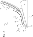
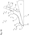
- the Figures 1A and 1B show the share point 10 according to the invention in a side view and in a sectional view.
- the share tip 10 comprises three areas.
- a first region 14 has a cutting edge 20, which is arranged at a free end in the longitudinal extension direction of the blade tip 10.
- the cutting edge 20 represents the narrowest portion of the blade tip 10 and has in the FIG. 1 a width between 20 mm to 30 mm, preferably 25 mm.
- the first region 14 and thus also the cutting edge 20 form a wedge-shaped form and enclose an angle between 25 ° and 45 °.
- the wedge-shaped shape of the first region 14 allows the coulter tip to more easily penetrate the soil during the tillage process.
- a second region 16 adjoins the first region 14 in the longitudinal direction of the blade tip 10 and is arranged downstream of this.
- the second region 16 has a running surface 22.
- the tread 22 may be at least partially arcuate and has a radius between 80 mm and 120 mm lock in. Preferably, the radius may be 100 mm.
- the second region 16 terminates with an elevation at the end of the at least partially curved running surface 22 on the front side of the blade tip 10, which elevation forms a first undercut 40a.
- In the first undercut 40a engages a corresponding end of the baffle 28 (not shown here) in the assembled state of the share tip 10 on a coulter handle 26 (see. FIG. 2 and FIG. 3 ) one.
- a second undercut 40b is provided, in which in the mounted state of the blade tip 10 on a coulter handle 26, the free end of the coulter handle 26 can lie correspondingly.
- the length of the first region 14 and the second region 16 of the blade tip 26 is in total 200 mm to 260 mm, preferably 230 mm. Thus, the sum of the lengths of the first region 14 and the second region 16 is at least five times the width of the cutting edge 20.
- the share tip 10 can be divided into a third area 18, which adjoins the second area 16 in the longitudinal extension direction of the blade tip 10.
- the third region 18 of the blade tip 10 forms a fastening region 24.
- the third region 18 formed as a fastening region 24 comprises at least three recesses 50a, 50b, 50c, which are spaced apart from one another. In each case at least three recesses 50a, 50b, 50c, a fastening means of the at least three attachment means (not shown here) are performed so that the share tip 10 at least partially on a share handle 26 (not shown here) by means of the third region 18 formed as a fastening region 24 ).
- the shape of the third region 18 designed as a fastening region 24 is arc-shaped at least in sections and includes a radius of 565 mm and 585 mm, preferably 575 mm.
- the third region 18 designed as a fastening region 24 has a width that is at least one fifth wider than the blade tip 10. Thereafter, the width of the third region 18 designed as a fastening region 24 measures between 30 mm and 40 mm, preferably 35 mm.
- the first region 14 and at least partially the second region 16 of the blade tip 10 wear elements 30 are assigned.
- a first wear element 30a is arranged in the first region 14 of the blade tip 20 and forms an undercut, wherein the undercut is formed corresponding to the shape of the cutting edge 20.
- the first wear element 30a is L-shaped.
- a second wear element 30b in the first region 14 of Scharspitze 10 provided.
- the second wear element 30b is formed as a plate and is flush with the first wear element 30a.
- the second wear element 30b may well also extend into the second region 16 of the blade tip.
- a third wear element 30c is provided at least in regions in the second region 16 of the blade tip 10.
- the third wear element 30c forms a small plate and, due to the at least partial arrangement in the second region 16 of the blade tip 10, is part of the at least partially curved running surface 22.
- the wear elements 30 are each formed from a wear-resistant material, preferably from a hard metal. Due to the use of wear elements 30, the share tip 10 is at least partially equipped with carbide.
- the blade tip 10 initially has a wedge-shaped widening with respect to a working direction, which encloses an angle of approximately 25 ° to 45 °, which in turn is followed by a wedge-shaped widening which encloses an angle between approximately 4 ° to 8 °, again followed by a conical taper which encloses an angle of between about 2 ° to 6 °.
- the wedge-shaped widenings and the conical taper extend in particular over the first region 14 and at least partially over the second region 16 of the blade tip 10.
- the conical taper is followed in particular by the at least partially arcuate running surface 22 of the second region 16 of the blade tip 10.
- the share tip 10 has on its rear side a clearance angle ⁇ in relation to a ground 36 to be processed.
- the clearance angle ⁇ includes an angle between 4 ° and 8 °, preferably an angle of 6 °. Due to the clearance angle ⁇ , the blade tip 10 is formed obliquely to the bottom 36 extending.
- FIGS. 2 and 3 show the share point 10 in a mounted state on a share handle 26 in different views and perspectives.
- a baffle 28 is provided on the front of the share handle 26 and a Scharschen 26 on the back of the share handle 26, which as a result form a share system 12.
- the skewer 26 has a width between 20 mm and 30 mm, preferably a width of 25 mm, and forms with respect to the ground to be machined 36 an angle between 7 ° to 13 °, preferably an angle of 10 °, ie the skewer 26 is bent with respect to the ground 36 to be machined.
- the share handle 26 has at least two recesses into which a fixing unit 38 for connecting the share handle 26 to a frame of an agricultural machine can be fixed.
- the baffle 28 is formed corresponding to the shape of the coulter handle 26 and arranged on the front of the coulter stick 26.
- the baffle 28 encloses an angle between 100 ° and 108 °, preferably an angle between 104 ° with respect to the ground 36 to be processed.
- At least one receiving unit 44 at least partially receives the handle arm 26 and ensures alignment of the guide plate 28 during assembly on the handle arm 26.
- the width of the at least one receiving unit 44 corresponds to the width of Scharstiels 26 and is thus between 20 mm and 30 mm, preferably 25 mm wide.
- At least one latching lug 46 is provided at the opposite end of the at least one receiving unit 44, which in the assembled state can engage in a corresponding opening formed by a groove 48 of the third area 18 designed as a fastening area 24.
- the at least one detent 46 is formed as a square elevation.
- the sharpening tip 10 When the sharpening tip 10 is in the assembled state, it is fixed on at least a section of a front side of a share handle 26 via the third area 18, which is designed as a fastening area 24, by means of at least three fastening means 42a, 42b, 42c.
- the third region 18 designed as a fastening region 24 has at least three recesses 50a, 50b, 50c in the form of bores which are arranged at a distance from one another.
- a first fastener 42a and a second fastener 42b connect the share tip 10 to the coulter 26, while a third fastener 42c connects the coulter tip 10 and the baffle 28 to the coulter 26.
- the first fastening means 42a and the second fastening means 42b are arranged in the region of a free end of the coulter handle 26, while the third fastening means 42c is provided at the adjacent end of the third region 18 of the coulter tip 10 formed as a fastening region 24, ie the third region designed as a fastening region 24 18 is shaped such that the Fixing portion 24 formed third region 18 between baffle 28 and a coulter handle 26 is mountable.
- the at least three fastening means 42a, 42b, 42c are designed as screw connections, so that by means of the at least three fastening means 42a, 42b, 42c, an effective releasable connection between the blade tip 10, the guide plate 28 and the skewer 26 is effected.
- the baffle 28 also ensures an overlap of the at least three fastening means 42a, 42b, 42c.
- the at least three fastening means 42a, 42b, 42c are protected against wear and contamination, ie the guide plate 28 extends over the third region 18 designed as a fastening region 24.
- the Scharschreiben 34 includes at least one receptacle which extends continuously along the longitudinal direction of the Scharschreibens 34.
- the at least receiving the Scharschreibens 34 corresponds to the width of the share handle 26 and serves to receive the share handle 26 at least in sections. Due to this, the shape of the coulter back 34, in particular its at least one receptacle, corresponding to the shape of the coulter handle 26 is formed.
- the Scharschreiben 34 comprises on its rear side at least one channel (not shown here), which extends along the longitudinal direction of the Scharschreibens 34.
- the at least one channel By means of the at least one channel, granular and / or liquid material, such as fertilizer, is deposited in the soil 34 to be processed.
- the Scharschreiben 34 is fixed by means of two laterally arranged further attachment means on the share handle 26, so that between the Scharschreiben 34 and the share handle 26 an acting releasable connection is formed.
- the two laterally arranged further fastening means are each guided by two laterally arranged recesses of the Scharschreibens 34 and the share handle 26 and then fixed.
- the FIG. 4 shows the baffle 28 in a perspective view.
- the baffle 28 comprises at one end an at least receiving unit 44, wherein the width of the at least one receiving unit 44 corresponds to a width of the handle arm 26. Thereafter, the at least one receiving unit 44 between 20 mm and 30 mm, preferably 25 mm wide.
- the at least one receiving unit 44 can rest in the assembled state on the front of the handle arm 26.
- at least one locking lug 46 is provided, which in the mounted state can engage in a corresponding opening in the form of a groove 48 of the third region 18 designed as a fastening region 24.
- the at least one detent 46 is formed as a square elevation.
Abstract
Es ist eine Scharspitze zur Verwendung in einem Scharsystem zur Bodenbearbeitung offenbart. Die Scharspitze weist einen eine Schneidkante aufweisenden ersten Bereich, einen an den ersten Bereich anschließenden und eine Lauffläche aufweisenden zweiten Bereich, sowie einen dritten, an den zweiten Bereich anschließenden Befestigungsbereich, wobei die Scharspitze eine maximale Breite aufweist, welche zwischen dem einfachen und maximal dem doppelten der Breite eines Scharstiels entspricht, an welchem diese montiert ist. Die Scharspitze zeichnet sich aus, dass der Befestigungsbereich derartig geformt ist, dass die Scharspitze zwischen einem dem Scharsystem zugeordneten Leitblech und einem Zinkenstiel montierbar ist.There is disclosed a coulter tip for use in a coulter system for tillage. The blade tip has a first region having a cutting edge, a second region adjoining the first region and having a tread, and a third attachment region adjoining the second region, wherein the blade tip has a maximum width which is between the single and a maximum of twice corresponds to the width of a coulter on which it is mounted. The share point is characterized in that the attachment area is shaped in such a way that the share point can be mounted between a guide plate associated with the share system and a tine handle.
Description
Die vorliegende Erfindung betrifft eine Scharspitze für ein Scharsystem mit den Merkmalen des Oberbegriffs des unabhängigen Anspruchs 1. Weiterhin betrifft die Erfindung ein Scharsystem, insbesondere für die landwirtschaftliche Bodenbearbeitung.The present invention relates to a share point for a coulter system having the features of the preamble of
Scharspitzen können Bestandteil eines Scharsystems sein, welches Scharsystem insbesondere zur Bodenbearbeitung eingesetzt wird. Das Scharsystem kann sich aus einem Scharstiel, aus einem Leitblech und aus einer Scharspitze zusammensetzen. Der Scharstiel kann mittels geeigneter Befestigungsmittel an einem Rahmen einer landwirtschaftlichen Maschine angeordnet werden. Die Scharspitze kann hingegen am freien Ende des Scharstiels fixiert sein und so in einer abgesenkten Position des Scharstiels in den Boden eingreifen. Das Scharsystem, insbesondere die Scharspitze kann dazu dienen, den Boden aufzulockern.Sharp points can be part of a share system, which share system is used in particular for tillage. The coulter system can be composed of a coulter handle, a guide plate and a coulter tip. The skewer can be arranged by means of suitable fastening means on a frame of an agricultural machine. The share point, however, can be fixed at the free end of the coulter handle and thus engage in a lowered position of the coulter in the ground. The coulter system, especially the coulter tip, can serve to loosen the soil.
Im Stand der Technik sind zahlreiche Ausgestaltungen einer Scharspitze bekannt. Die
Der Gegenstand der
Der Gegenstand der
Nachteilig ist, dass es sich bei den bekannten Gegenständen jeweils um ein sehr breites Schar handelt. So könnte während eines Bodenbearbeitungsprozesses unerwünscht Erde vermischt werden. Zugleich sind die Befestigungsmittel freiliegend und unterliegen daher einem hohen Verschleiß und sind folglich einer hohen Verschmutzungsgefahr ausgesetzt.The disadvantage is that each of the known objects is a very broad group. Thus, undesirable soil could be mixed during a tillage process. At the same time the fasteners are exposed and therefore subject to high wear and are therefore exposed to a high risk of contamination.
Ein Gerät zur Vorbereitung des Bodens für eine Reihensaat ist durch die
Beim Gegenstand der
Die
Nachteilig an diesen bekannten Systemen ist, dass sich der Zinken aus einer Vielzahl von Einzelteilen zusammensetzt, was einen erhöhten Teileaufwand und einen erhöhten Kostenaufwand zur Folge hat.A disadvantage of these known systems that the tines composed of a variety of items, which has an increased parts cost and increased costs result.
Der Erfindung liegt daher die Aufgabe zugrunde, eine Scharspitze bzw. ein Scharsystem zur Verfügung zu stellen, bei welcher/welchen die im Stand der Technik bekannten Nachteile zumindest teilweise überwunden werden können und tief gelockert werden kann, ohne Erde zu vermischen. Das Scharsystem soll zugleich einen unkomplizierten Aufbau besitzen, schmal ausgebildet sein und den Teileaufwand reduzieren.The invention is therefore based on the object to provide a share tip or a share system available in which / which in the prior art known disadvantages can be at least partially overcome and can be loosened deeply, without mixing soil. The coulter system should also have a straightforward structure, be narrow and reduce the parts cost.
Diese Aufgaben werden durch eine Scharspitze zur Verwendung in einem Scharsystem zur Bodenbearbeitung im unabhängigen Anspruch 1 sowie durch ein solches Scharsystem mit den Merkmalen des unabhängigen Anspruchs 10 gelöst. Weitere vorteilhafte Ausgestaltungen und Weiterbildungen der Erfindung sind in den jeweiligen abhängigen Ansprüchen beschrieben.These objects are achieved by a coulter tip for use in a tilling system in
Zur Lösung der genannten Aufgaben schlägt die Erfindung eine Scharspitze zur Verwendung in einem Scharsystem zur Bodenbearbeitung vor. Die erfindungsgemäße Scharspitze weist zumindest einen eine Schneidkante aufweisenden ersten Bereich auf. Der erste Bereich kann an einem freien Ende der Scharspitze ausgebildet sein und sich zumindest bereichsweise entlang der Längserstreckungsrichtung der Scharspitze erstrecken.To solve the stated objects, the invention proposes a share point for use in a coulter system for soil cultivation. The share point according to the invention has at least one first area having a cutting edge. The first region may be formed at a free end of the blade tip and extend at least partially along the longitudinal extension direction of the blade tip.
Weiter umfasst die Scharspitze einen an den ersten Bereich anschließenden und eine Lauffläche aufweisenden zweiten Bereich. Der zweite Bereich kann sich in Längserstreckungsrichtung der Scharspitze erstrecken und dem ersten Bereich nachgeordnet sein. Der Übergang zwischen dem ersten Bereich und dem zweiten Bereich der Scharspitze kann fließend erfolgen.Furthermore, the share tip comprises a second area adjoining the first area and having a running surface. The second region may extend in the longitudinal direction of the blade tip and be arranged downstream of the first region. The transition between the first region and the second region of the share tip can be done fluently.
Die Scharspitze weist einen dritten, an den zweiten Bereich anschließenden Befestigungsbereich auf. Der dritte Bereich kann sich in Längserstreckungsrichtung der Scharspitze erstrecken und dem zweiten Bereich nachgeordnet sein. Der Übergang zwischen dem zweiten Bereich und dem dritten Bereich der Scharspitze kann fließend erfolgen. Der Befestigungsbereich kann zumindest eine Ausnehmung, beispielsweise in Form von zumindest einer Bohrung umfassen. Die zumindest eine Ausnehmung kann zur Durchführung von zumindest einem Befestigungsmittel dienen, welches zumindest eine Befestigungsmittel zur Festsetzung der Scharspitze an dem Scharstiel sorgt, d.h. der Befestigungsbereich kann dazu dienen, die Scharspitze an einem freien Ende eines Scharstiels mittels zumindest eines Befestigungsmittels zu fixieren.The share point has a third attachment area adjoining the second area. The third region may extend in the longitudinal extension direction of the blade tip and be arranged downstream of the second region. The transition between the second region and the third region of the share tip can be done fluently. The attachment region may comprise at least one recess, for example in the form of at least one bore. The at least one recess may serve to carry out at least one fastening means which provides at least one fixing means for fixing the share point to the share handle, i. the attachment region can serve to fix the share tip to a free end of a share handle by means of at least one fastening means.
Die Scharspitze weist eine maximale Breite auf, welche zwischen dem einfachen und maximal dem doppelten der Breite eines Scharstiels entspricht, an welchem die Scharspitze montiert ist, d.h. die Breite der Scharspitze, insbesondere der Befestigungsbereich ausgebildete dritte Bereich kann eine Breite zwischen ein- bis zweimal einer Breite des Scharstiels entsprechen. Der als Befestigungsbereich ausgebildete dritte Bereich kann folglich eine maximale Breite der Scharspitze einnehmen.The share point has a maximum width which corresponds to between the simple and at most twice the width of a share handle on which the share point is mounted, ie the width of the share point, in particular the Fixing portion formed third region may correspond to a width between one to two times a width of the share handle. The third region designed as a fastening region can consequently assume a maximum width of the blade tip.
Die Montage der Scharspitze an zumindest einem Abschnitt des Scharstiels kann bedeuten, dass die Scharspitze mittels des als Befestigungsbereichs ausgebildeten dritten Bereichs an einer Vorderseite des Scharstiels fixierbar ist.The assembly of the share tip on at least one section of the share handle can mean that the share point can be fixed by means of the third area designed as a fastening area on a front side of the share handle.
Der Scharstiel kann dazu dienen, die an den Scharstiel fixierte Scharspitze einem Rahmen einer landwirtschaftlichen Maschine anzubinden. Hierzu kann der Scharstiel an einem Ende zumindest eine Ausnehmung aufweisen, so dass der Scharstiel mittels einer Befestigungseinheit am Rahmen einer landwirtschaftlichen Maschine fixiert werden kann. Die Anbindung des Scharstiels am Rahmen einer landwirtschaftlichen Maschine kann lösbar und/oder unlösbar ausgebildet sein. Als lösbare Verbindungen können beispielsweise Schraubverbindungen und/oder jegliche weitere Verbindungsmethoden verwendet werden. Die zumindest eine Ausnehmung an dem Rahmen zugewandten Ende des Scharstiels kann rund und/oder quadratisch und/oder dergleichen ausgebildet sein.The coulter handle can be used to tie the coulter tip fixed to the coulter stick to a frame of an agricultural machine. For this purpose, the share handle can have at least one recess at one end, so that the share handle can be fixed by means of a fixing unit on the frame of an agricultural machine. The connection of the coulter handle on the frame of an agricultural machine can be made detachable and / or insoluble. As detachable connections, for example, screw connections and / or any further connection methods can be used. The at least one recess on the frame facing the end of the share handle may be round and / or square and / or the like.
Der Scharstiel kann je nach Ausführungsform eine unterschiedliche Form ausbilden. Vorzugsweise kann sich der Scharstiel gebogen zum zu bearbeitenden Boden erstrecken, so dass der Scharstiel in Bezug auf den zu bearbeitenden Boden einen Winkel zwischen 7° bis 13°, vorzugsweise einen Winkel von 10°, einschließen kann. Der Scharstiel kann eine Breite zwischen 20 mm und 30 mm aufweisen. Vorzugsweise kann die Breite des Scharstiels 25 mm betragen.The share handle can form a different shape depending on the embodiment. Preferably, the skewer can extend curved to the soil to be processed, so that the skewer can with respect to the soil to be processed an angle between 7 ° to 13 °, preferably an angle of 10 °, can include. The skewer can have a width between 20 mm and 30 mm. Preferably, the width of the coulter handle can be 25 mm.
Die Scharspitze zeichnet sich dadurch aus, dass der Befestigungsbereich derartig geformt ist, dass die Scharspitze zwischen einem dem Scharsystem zugeordneten Leitblech und einem Zinkenstiel montierbar ist. Dies kann bedeuten, dass eine Rückseite des als Befestigungsbereichs ausgebildeten dritten Bereichs an einem freien Ende des Scharstiels aufliegen kann, während auf der Vorderseite des als Befestigungsbereich ausgebildeten dritten Bereichs ein Leitblech aufliegen kann. Das Scharsystem kann durch einen Scharstiel, eine Scharspitze, einen Scharrücken und ein Leitblech gebildet werden.The share point is characterized in that the attachment area is shaped in such a way that the share point can be mounted between a guide plate assigned to the share system and a tine handle. This can mean that a rear side of the third region designed as a fastening region can rest on a free end of the coulter handle, while a guide plate can rest on the front side of the third region designed as a fastening region. The Scharsystem can be formed by a Scharstiel, a Scharspitze, a Scharrücken and a baffle.
Das Leitblech kann auf der Vorderseite eines Scharstiels fixiert sein. Die anliegende Fläche des Leitblechs auf der Vorderseite des Scharstiels kann korrespondierend zur Form des Scharstiels ausgebildet sein. Bei Montage des Leitblechs auf der Vorderseite des Scharstiels kann das Leitblech in Bezug auf den zu bearbeitenden Boden einen Winkel zwischen 100° und 108° einschließen. Vorzugsweise kann der Winkel zwischen dem Leitblech und dem zu bearbeitenden Boden 104° betragen. Es kann vorgesehen sein, dass das Leitblech eine Breite zwischen 20 mm und 40 mm aufweist. Vorzugsweise kann die Breite des Leitblechs 35 mm betragen.The baffle may be fixed to the front of a coulter handle. The adjoining surface of the baffle on the front of the coulter handle may be formed corresponding to the shape of the coulter handle. When mounting the baffle on the front of the coulter handle, the baffle in relation to the soil at an angle between 100 ° and 108 °. Preferably, the angle between the baffle and the floor to be processed can be 104 °. It can be provided that the baffle has a width between 20 mm and 40 mm. Preferably, the width of the baffle can be 35 mm.
Es kann vorgesehen sein, dass das Leitblech an einem Ende mindestens eine Aufnahmeeinheit umfasst, welche mindestens eine Aufnahmeeinheit der Breite des Scharstiels entspricht, d.h. die mindestens eine Aufnahmeeinheit kann den Scharstiel zumindest abschnittsweise aufnehmen und auf der Vorderseite des Scharstiels aufliegen. Folglich kann die mindestens eine Aufnahmeeinheit zwischen 20 mm und 30 mm, vorzugsweise 25 mm, breit sein. Am gegenüberliegenden Ende der mindestens einen Aufnahmeeinheit kann das Leitblech zumindest eine Rastnase umfassen, welche in eine korrespondierende Öffnung in Form einer Nut des als Befestigungsbereich ausgebildeten dritten Bereichs eingreifen kann. Damit ist die zumindest eine Rastnase dem als Befestigungsbereich ausgebildeten dritten Bereich zugewandt. Die zumindest eine Rastnase kann als quadratische oder zylindrische oder konische ausgebildete Erhebung ausgebildet sein. Denkbar wäre es auch, ein Leitblech ohne zumindest einer Rastnase auszubilden.It can be provided that the guide plate comprises at one end at least one receiving unit, which corresponds to at least one receiving unit, the width of the share handle, i. the at least one receiving unit can at least partially receive the share handle and rest on the front of the share handle. Consequently, the at least one receiving unit may be between 20 mm and 30 mm, preferably 25 mm wide. At the opposite end of the at least one receiving unit, the guide plate may comprise at least one latching lug, which may engage in a corresponding opening in the form of a groove of the third region designed as a fastening region. Thus, the at least one locking lug faces the third region designed as a fastening region. The at least one latching lug may be formed as a square or cylindrical or conical survey formed. It would also be conceivable to design a baffle without at least one latching lug.
Die Fixierung des als Befestigungsbereichs ausgebildeten dritten Bereichs kann zwischen dem Leitblech und dem Scharstiel mittels einer wirkenden lösbaren Verbindung erfolgen. Die wirkende lösbare Verbindung kann insbesondere durch zumindest einem Befestigungsmittel erfolgen. Das zumindest eine Befestigungsmittel kann durch die zumindest eine Ausnehmung des Leitblechs des als Befestigungsbereich ausgebildeten dritten Bereichs und des Scharstiels geführt werden. Die zumindest eine Ausnehmung kann im Abschnitt des als Befestigungsbereich ausgebildeten dritten Bereichs vorgesehen sein, insbesondere am Scharstiel anliegenden Ende. Als Befestigungsmittel können Schraubverbindungen oder jegliche weitere lösbare Verbindungsmethoden eingesetzt werden. Die zumindest eine Ausnehmung kann zylindrisch, quadratisch und/oder konisch gebildet sein.The fixing of the third region designed as a fastening region can take place between the guide plate and the coulter handle by means of an acting releasable connection. The acting detachable connection can be effected in particular by at least one fastening means. The at least one fastening means can be guided through the at least one recess of the guide plate of the third region designed as a fastening region and the coulter handle. The at least one recess can be provided in the section of the third region designed as a fastening region, in particular at the butt end. As fasteners screw or any other releasable connection methods can be used. The at least one recess may be cylindrical, square and / or conical.
Die Fixierung des als Befestigungsbereich ausgebildeten dritten Bereichs kann mittels mehrerer Befestigungselementen erfolgen, insbesondere durch zumindest zwei Befestigungsmittel. Ein erstes der zumindest zwei Befestigungsmittel kann den als Befestigungsbereich ausgebildeten dritten Bereich mit dem Scharstiel verbinden, während ein zweites Befestigungsmittel das Leitblech und den als Befestigungsbereich ausgebildeten dritten Bereich an den Scharstiel anbinden.The fixing of the third region designed as a fastening region can be effected by means of a plurality of fastening elements, in particular by at least two fastening means. A first of the at least two fastening means can connect the third region designed as a fastening region to the handle stem, while a second fastening means bind the guide plate and the third region designed as a fastening region to the coulter handle.
Das erste Befestigungsmittel der zumindest zwei Befestigungsmittel kann im Bereich eines freien Endes des Scharstiels und das zweite Befestigungsmittel kann am anliegenden Ende des als Befestigungsbereich ausgebildeten dritten Bereichs am Scharstiel angeordnet sein. Diese Anordnung der zumindest zwei Befestigungsmittel kann dafür sorgen, dass die auf die Scharspitze und das Leitblech wirkenden Kräfte während eines Bodenbearbeitungsprozesses kompensieren können. Bodenbearbeitungsprozess kann bedeuten, dass der Scharspitze über den Scharstiel im Boden abgesenkt ist und der Boden gelockert wird. Dabei kann beim Lockern des Bodens im Boden selbst keine Erde an die Oberfläche transportiert werden kann.The first attachment means of the at least two attachment means may be arranged in the region of a free end of the coulter handle and the second attachment means may be arranged on the adjoining end of the third region formed as a fastening region on the coulter handle. This arrangement of the at least two fastening means can ensure that the forces acting on the blade tip and the baffle can compensate during a tillage process. Tillage process may mean that the share tip is lowered over the share handle in the ground and the soil is loosened. In this case, when loosening the soil in the soil itself no earth can be transported to the surface.
In einer weiteren Ausführungsform können zumindest drei Befestigungsmittel zur Anbindung der Scharspitze an dem Scharstiel verwendet werden. Bei Verwendung von zumindest drei Befestigungsmittel können ein erstes und ein zweites der zumindest drei Befestigungsmittel den als Befestigungsbereich ausgebildeten dritten Bereich der Scharspitze mit dem Scharstiel und ein drittes Befestigungsmittel das Leitblech und den als Befestigungsbereich ausgebildeten dritten Bereich der Scharspitze mit dem Scharstiel verbinden. Die Anordnung der zumindest drei Befestigungsmittel kann so erfolgen, dass das erste Befestigungsmittel und das zweite Befestigungsmittel im Bereich eines freien Endes des Scharstiels angeordnet sind. Das erste Befestigungsmittel und das zweite Befestigungsmittel sind dabei zueinander beabstandet. Das dritte Befestigungsmittel kann am anliegenden Ende des als Befestigungsbereich ausgebildeten dritten Bereichs der Scharspitze angeordnet sein und kann zugleich zum ersten und zum zweiten Befestigungsmittel beabstandet sein.In a further embodiment, at least three fastening means can be used to connect the share point to the share handle. When using at least three fastening means, a first and a second of the at least three fastening means can connect the third region of the blade tip formed as a fastening region with the coulter handle and a third fastening means the baffle and formed as a mounting region third portion of the coulter with the coulter. The arrangement of the at least three fastening means can be carried out such that the first fastening means and the second fastening means are arranged in the region of a free end of the coulter handle. The first attachment means and the second attachment means are spaced from each other. The third fastening means can be arranged at the adjoining end of the third region of the blade tip formed as a fastening region and can at the same time be spaced apart from the first and the second fastening means.
Alternativ kann die wirkende Verbindung zwischen dem als Befestigungsbereich ausgebildeten dritten Bereich und des Scharstiels als auch zwischen dem Leitblech, dem als Befestigungsbereich ausgebildeten dritten Bereich und des Scharstiels unlösbar ausgebildet sein. Als Befestigungsmittel können form- und/oder stoffschlüssige Verbindungen, wie Nietverbindungen und/oder Schweißverbindungen und/oder Klebverbindungen, ggf. auch Hartlötverbindungen, eingesetzt werden. Bei der Verwendung von mehreren Befestigungsmitteln kann zumindest ein und/oder mehrere Befestigungsmittel unlösbar ausgebildet sein, während ein zweites und/oder mehrere Befestigungsmittel lösbar ausgebildet sein kann/können. Jegliche weitere Verbindungsmethoden zur Fixierung des als Befestigungsabschnitt ausgebildeten dritten Bereichs der Scharspitze und des Leitblechs an den Scharstiel sind denkbar.Alternatively, the operative connection between the third region formed as a fastening region and the coulter handle and between the guide plate, the third region formed as a fastening region and the coulter handle can be made non-detachable. As fastening means can form and / or cohesive connections, such as riveted joints and / or welded joints and / or glued joints, possibly also brazing used. When using a plurality of fastening means, at least one and / or a plurality of fastening means may be designed to be insoluble, while a second and / or a plurality of fastening means may be detachable. Any further connection methods for fixing the third region of the share tip and the guide plate to the share handle designed as a fastening section are conceivable.
Neben einem Leitblech und einer Scharspitze kann am Scharstiel ein Scharrücken vorgesehen sein, welcher auf der Rückseite des Scharstiels mittels wenigstens eines seitlich angeordneten weiteren Befestigungsmittels fixierbar ist. Der Scharrücken kann wenigstens eine Aufnahme umfassen, welche wenigstens Aufnahme sich durchgehend entlang der Längserstreckungsrichtung des Scharrückens erstrecken kann und welche wenigstens Aufnahme der Breite des Scharstiels entsprechen kann. Der Scharstiel kann folglich von der wenigstens einen Aufnahme des Scharrückens zumindest abschnittsweise aufgenommen werden. Danach kann die Form des Scharrückens zumindest näherungsweise der Form des Scharstiels entsprechen und in Bezug auf den zu bearbeitenden Boden gebogen ausgebildet sein. Der Scharrücken, insbesondere dessen Rückseite, kann in Bezug auf den zu bearbeitenden Boden relativ steil ausgebildet sein, so dass während eines Bodenbearbeitungsprozesses nur wenig Erde bewegt wird. Das Bewegen von wenig Erde während des Bodenbearbeitungsprozesses kann dadurch unterstützt werden, dass der Scharrücken auf der Rückseite des Scharstiels angeordnet ist und damit der Scharspitze in Bezug auf die Arbeitsrichtung nachgeordnet ist. Der Scharrücken kann durch bereits gelockerten Boden gleiten, was für einen geringeren Zugkraftbedarf sorgen kann. Der Scharrücken kann auf seiner Rückseite mindestens einen Kanal aufweisen, welcher sich längsgerichtet entlang der Form des Scharrückens erstrecken kann. Mittels des mindestens einen Kanals kann körniges und/oder flüssiges Gut, insbesondere Dünger in den Boden ausgebracht werden.In addition to a guide plate and a share tip, a share can be provided on the share handle, which can be fixed on the rear side of the share handle by means of at least one laterally arranged further attachment means. The Scharrücken may comprise at least one receptacle, which at least receptacle may extend continuously along the longitudinal direction of the Scharrückens and which may at least accommodate the width of the Scharstiels. The share handle can consequently be received at least in sections by the at least one receptacle of the coulter back. Thereafter, the shape of the coulter back can at least approximately correspond to the shape of the coulter handle and be formed bent relative to the ground to be processed. The Scharrücken, in particular its back, may be relatively steep with respect to the soil to be processed, so that during a tillage process only little earth is moved. The movement of little soil during the tillage process can be assisted by the fact that the Scharrücken is arranged on the back of the share handle and thus the share tip is arranged downstream with respect to the working direction. The Scharrücken can slide through already loosened soil, which can provide a lower traction requirement. The Scharrücken may have on its back at least one channel, which may extend longitudinally along the shape of the Scharrückens. By means of the at least one channel, granular and / or liquid material, in particular fertilizer, can be discharged into the soil.
Eine Weiterbildung der Erfindung kann vorsehen, dass der erste Bereich keilförmig gebildet ist und einen Winkel zwischen 25° und 45° einschließt. Die keilförmige Form des ersten Bereichs kann das Eindringen der Scharspitze in den Boden während des Bodenbearbeitungsprozesses erleichtern.A development of the invention may provide that the first region is wedge-shaped and forms an angle between 25 ° and 45 °. The wedge-shaped shape of the first region may facilitate the penetration of the share tip into the soil during the tillage process.
Es kann vorgesehen sein, dass dem ersten Bereich sowie zumindest abschnittsweise dem zweiten Bereich jeweils Verschleißelemente zugeordnet sind. Die Verschleißelemente können zum Schutz der Scharspitze dienen und bei Bedarf, insbesondere bei Verschleißerscheinungen, ausgetauscht werden. Alternativ kann bei Verschleißerscheinungen die Scharspitze im Gesamten ausgetauscht werden. Vorzugsweise können drei Verschleißelemente vorgesehen sein, welche sich über den ersten Bereich und zumindest abschnittsweise über den zweiten Bereich der Scharspitze erstrecken. Das erste und das zweite der drei Verschleißelemente können im ersten Bereich der Scharspitze und das dritte Verschleißelement kann im ersten Bereich und im zweiten Bereich der Scharspitze angeordnet sein. Die Verschleißelemente können aus wenigstens einem Stahl und/oder aus jeglichen weiteren verschleißbeständigen Materialien gebildet sein. Bevorzugtes Material der Verschleißelemente kann wenigstens ein Hartmetall sein. Dies kann bedeuten, dass die Scharspitze, insbesondere der erste Bereich und zumindest abschnittsweise der zweite Bereich der Scharspitze, mit Hartmetall bestückt sein kann/können.It can be provided that wear elements are assigned to the first region and at least partially to the second region. The wear elements can be used to protect the share tip and if necessary, especially when worn, be replaced. Alternatively, in the case of signs of wear, the blade tip can be replaced as a whole. Preferably, three wear elements may be provided which extend over the first region and at least in sections over the second region of the blade tip. The first and the second of the three wear elements can be arranged in the first region of the blade tip and the third wear element can be arranged in the first region and in the second region of the blade tip. The wear elements can be made of at least one steel and / or any other wear-resistant Be made of materials. Preferred material of the wear elements may be at least one hard metal. This can mean that the share point, in particular the first area and at least sections of the second area of the share point, can be equipped with hard metal.
Eine Ausführungsform der Erfindung kann vorsehen, dass die Scharspitze zunächst in Bezug auf eine Arbeitsrichtung eine keilförmige Aufweitung aufweist, welche einen Winkel von 25° bis 45° einschließt, wobei an diesen wiederum eine keilförmige Aufweitung anschließt, welche einen Winkel zwischen 4° bis 8° einschließt, wobei wiederum an diese eine konische Verjüngung anschließt, welche einen Winkel zwischen 2° bis 6° einschließt.An embodiment of the invention may provide that the coulter tip initially has a wedge-shaped widening with respect to a working direction, which encloses an angle of 25 ° to 45 °, which in turn is followed by a wedge-shaped widening, which forms an angle between 4 ° to 8 ° which in turn is followed by a conical taper which encloses an angle between 2 ° to 6 °.
Es kann vorgesehen sein, dass sich an die Verjüngung eine zumindest abschnittsweise bogenförmige Lauffläche anschließt. Die zumindest abschnittsweise bogenförmige Laufläche kann insbesondere im zweiten Bereich der Scharspitze angeordnet sein und einen Radius zwischen 80 mm und 120 mm einschließen. Vorzugsweise kann der Radius der zumindest abschnittsweisen bogenförmigen Lauffläche 100 mm betragen. Aufgrund der zumindest abschnittsweisen bogenförmigen Lauffläche kann sich die Scharspitze zumindest näherungsweise an die vorzugsweise gebogene Form des Scharstiels anpassen. Es hat sich als vorteilig erwiesen, je enger der Radius der zumindest abschnittsweisen bogenförmigen Lauffläche des zweiten Bereichs der Scharspitze gewählt ist, desto weniger Erde kann während des Bodenbearbeitungsprozesses aufgemischt werden.It can be provided that adjoins the taper at least partially arcuate tread. The at least partially arcuate running surface may in particular be arranged in the second region of the blade tip and enclose a radius between 80 mm and 120 mm. Preferably, the radius of the at least partially arcuate running surface can be 100 mm. Due to the at least partially curved running surface, the blade tip can at least approximately adapt to the preferably curved shape of the coulter handle. It has proven to be advantageous, the closer the radius of the at least partially arcuate running surface of the second region of the share tip is selected, the less soil can be mixed during the tillage process.
Die Erfindung kann weiter vorsehen, dass dem Befestigungsbereich zumindest eine Bohrung zur Montage der Scharspitze an einen Zinkenstiel zugeordnet ist. Die zumindest eine Bohrung kann als Beispiel für zumindest eine Ausnehmung stehen. Die zumindest eine Ausnehmung kann rund und/oder eckig ausgebildet sein. Durch die zumindest eine Ausnehmung kann zumindest ein Befestigungsmittel zur Fixierung des als Befestigungsbereich ausgebildeten dritten Bereichs der Scharspitze mit dem Leitblech an dem Scharstiel erfolgen.The invention may further provide that the attachment region is assigned at least one hole for mounting the share tip to a tine handle. The at least one bore may be an example of at least one recess. The at least one recess may be round and / or angular. By means of the at least one recess, at least one fastening means for fixing the third region of the blade tip formed as a fastening region to the guide plate on the coulter handle can take place.
Es kann vorgesehen sein, dass die zumindest eine Bohrung im montierten Zustand von einem Leitblech überdeckt wird. Das Leitblech kann damit zum Schutz des zumindest einen Befestigungsmittels beitragen, welches durch die zumindest eine Bohrung bzw. durch die zumindest eine Ausnehmung geführt wird. Je nach Anzahl der Befestigungsmittel und je nach Anzahl der Ausnehmungen können entsprechend mehr und/oder weniger Befestigungsmittel vom Leitblech überdeckt werden. So wäre es denkbar, dass bei zumindest zwei Befestigungsmittel ein Befestigungsmittel oder beide Befestigungsmittel vom Leitblech überdeckt werden können. Aufgrund der Überdeckung des zumindest einen Befestigungsmittels mittels des Leitblechs kann dieses vor Verschleiß und Verschmutzungen geschützt werden.It can be provided that the at least one bore in the assembled state is covered by a baffle. The guide plate can thus contribute to the protection of the at least one fastening means which is guided through the at least one bore or through the at least one recess. Depending on the number of fasteners and depending on the number of recesses can be correspondingly more and / or less fastener are covered by the baffle. Thus, it would be conceivable that with at least two fastening means one fastening means or both fastening means can be covered by the baffle. Due to the overlap of the at least one fastening means by means of the baffle this can be protected from wear and dirt.
Gemäß einem Ausführungsbeispiel kann vorgesehen sein, dass der erste und der zweite Bereich zusammen eine Länge aufweisen, welche wenigstens dem Fünffachen der Breite der Schneidkante entspricht. Eine Summe der Länge des ersten und des zweiten Bereichs der Scharspitze kann 200 mm bis 260 mm, vorzugsweise 230 mm, und die Breite der Schneidkante kann 20 mm bis 30 mm, vorzugsweise 25 mm, betragen.According to an exemplary embodiment, it can be provided that the first and the second region together have a length which corresponds at least to five times the width of the cutting edge. A sum of the length of the first and second portions of the blade tip may be 200 mm to 260 mm, preferably 230 mm, and the width of the cutting edge may be 20 mm to 30 mm, preferably 25 mm.
Es kann vorgesehen sein, dass eine Länge der Scharspitze, insbesondere unter Berücksichtigung der Länge des ersten Bereichs, des zweiten Bereichs und des dritten Bereichs der Scharspitze, und die Breite des Leitblechs im Verhältnis von sieben zu eins stehen.It can be provided that a length of the blade tip, in particular taking into account the length of the first region, the second region and the third region of the blade tip, and the width of the guide plate in the ratio of seven to one.
Es kann vorgesehen sein, dass die Schneidkante der schmalste Abschnitt dieser ist, und der Befestigungsbereich eine Breite aufweist, welche wenigstens um ein Fünftel breiter als diese ist. Danach kann der als Schneidkante ausgebildete erste Bereich der Scharspitze eine Breite von 20 mm bis 30 mm, vorzugsweise eine Breite von 25 mm, aufweisen und der als Befestigungsbereich ausgebildete dritte Bereich kann eine Breite von 30 mm bis 40 mm aufweisen. Bevorzugte Breite des als Schneidkante ausgebildeten ersten Bereichs kann 25 mm und eine bevorzugte Breite des als Befestigungsbereichs ausgebildeten dritten Bereichs kann 35 mm betragen.It can be provided that the cutting edge is the narrowest portion of this, and the mounting portion has a width which is at least one fifth wider than this. After that, the first region of the blade tip formed as a cutting edge may have a width of 20 mm to 30 mm, preferably a width of 25 mm, and the third region formed as a fastening region may have a width of 30 mm to 40 mm. The preferred width of the first region formed as a cutting edge may be 25 mm and a preferred width of the third region formed as a fastening region may be 35 mm.
Aufgrund solcher Längen- und Breitenverhältnisse der Scharspitze kann der zu bearbeitende Boden während eines Bodenbearbeitungsprozesses mit wenig Erdbewegung tief gelockert werden. Zugleich kann ein sehr schmales Schar umgesetzt werden.Due to such length and width ratios of the share tip, the soil to be worked can be loosened deeply during a tillage process with little earth movement. At the same time a very narrow crowd can be implemented.
Es kann vorgesehen sein, dass die Scharspitze rückseitig einen Freiwinkel in Bezug auf einen zu bearbeitenden Boden aufweist, welcher Freiwinkel zwischen 4° und 8° oder zwischen 5° und 7° liegt. Vorzugsweise kann der Freiwinkel der Scharspitze einen Wert von 6° aufweisen. Danach kann die Scharspitze schräg zu dem zu bearbeitenden Boden bzw. im Boden verlaufen. Durch die Ausbildung eines Freiwinkels kann die Scharspitze effektiver in den Boden eingreifen. Zugleich kann die Scharspitze mit weniger Kraftaufwand während des Bodenbearbeitungsprozesses in den Boden eindringen und im Boden geführt werden, so dass Verschleißerscheinungen an der Scharspitze reduziert werden können.It can be provided that the blade tip on the back has a clearance angle with respect to a ground to be processed, which clearance angle is between 4 ° and 8 ° or between 5 ° and 7 °. Preferably, the clearance angle of the share tip can have a value of 6 °. Thereafter, the share tip may be oblique to the ground to be processed or in the ground. By forming a clearance angle, the blade tip can engage more effectively in the ground. At the same time, the share point can penetrate with less force during the tillage process in the soil and in Ground are led so that wear on the share point can be reduced.
Es sei an dieser Stelle betont, dass sich alle Aspekte, Ausführungsvarianten, alle optionalen und/oder alternativen Gestaltungen und/oder Gestaltungsmerkmale der zuvor beschriebenen erfindungsgemäßen Scharspitze und ihrer Wirkungsweise ebenso auf das nachfolgend in verschiedenen Varianten beschriebene Scharsystem beziehen können. Wenn also zuvor teilweise bzw. vorrangig von der Scharspitze die Rede war, so beziehen sich alle in diesem Zusammenhang gemachten Aussagen gleichermaßen auf das Scharsystem. Gleiches gilt auch umgekehrt, so dass sich alle Aspekte, Ausführungsvarianten, alle optionalen und/oder alternativen Gestaltungen und/oder Gestaltungsmerkmale des nachfolgend beschriebenen erfindungsgemäßen Scharsystems und seiner Wirkungsweise und Einsatzmöglichkeiten ebenso auf die zuvor in verschiedenen Varianten beschriebene Scharspitze beziehen können. Wenn also nachfolgend teilweise bzw. vorrangig von einem Scharsystem die Rede sein wird, so beziehen sich alle in diesem Zusammenhang gemachten Aussagen gleichermaßen auf die Scharspitze.It should be emphasized at this point that all aspects, design variants, all optional and / or alternative designs and / or design features of the previously described inventive tip and its mode of action can also refer to the following described in different variants of the system. Thus, if previously mentioned in part or primarily by the Scharspitze, so all statements made in this context refer equally to the Scharsystem. The same applies vice versa, so that all aspects, design variants, all optional and / or alternative designs and / or design features of the inventive Scharsystems described below and its mode of action and applications can also refer to the share tip previously described in different variants. If, in the following, partial or senior discussion of a system of harsher will be made, then all statements made in this context refer equally to the head of the group.
Zur Lösung der oben genannten Aufgaben schlägt die Erfindung weiterhin ein Scharsystem mit den Merkmalen des unabhängigen Anspruchs 10 vor, welches Scharsystem insbesondere im Zusammenhang mit einer landwirtschaftlichen Bodenbearbeitung eingesetzt werden kann bzw. welches Scharsystem hierfür besonders geeignet ist. Das erfindungsgemäße Scharsystem umfasst wenigstens einen Scharstiel, eine lösbar an diesem Scharstiel montierte bzw. montierbare Scharspitze und zumindest ein Leitblech und/oder weitere damit zusammenwirkende und/oder in Wechselwirkung stehende Komponenten. Auch das Leitblech und/oder die weiteren Komponenten sind lösbar am Scharstiel montiert bzw. montierbar, wobei vorzugsweise gleichzeitig die Scharspitze mitmontiert wird, wenn das Leitblech am Scharstiel befestigt, fixiert bzw. montiert wird. Bei dem erfindungsgemäßen Scharsystem ist weiterhin vorgesehen, dass die Scharspitze einen ersten Bereich aufweist, der eine Schneidkante oder ggf. mehrere Schneidkanten aufweist. Ein sich in Längserstreckungsrichtung an den ersten Bereich anschließender zweiter Bereich weist eine Lauffläche auf. Schließlich umfasst die Scharspitze noch einen dritten Bereich, der sich an den zweiten Bereich anschließt, und der einen Befestigungsbereich bildet. Wenn in diesem Zusammenhang von den sich aneinander anschließenden Bereichen die Rede ist, so ist damit in erster Linie eine räumliche Aufeinanderfolge bzw. Aneinanderreihung in Längserstreckungsrichtung der Scharspitze gemeint, was jedoch keineswegs ausschließt, dass die eher funktionell beschriebenen bzw. bezeichneten drei Bereiche auch teilweise ineinander übergehen bzw. sich teilweise überdecken.In order to achieve the abovementioned objects, the invention furthermore proposes a coulter system having the features of
Die Scharspitze weist quer zu ihrer Längserstreckungsrichtung eine maximale Breite auf, welche zwischen dem einfachen und maximal dem doppelten der Breite des Scharstiels entspricht, an dem die Scharspitze lösbar montiert ist. Weiterhin ist vorgesehen, dass der Befestigungsbereich der Scharspitze zwischen dem, dem Scharsystem zugeordneten Leitblech und dem Scharstiel lösbar montiert ist. Wie erwähnt, können sich bei dem erfindungsgemäßen Scharsystem der erste Bereich mit der wenigstens einen Schneidkante, der zweite Bereich, der die Lauffläche aufweist und/oder bildet, sowie der dritte Bereich, der den Befestigungsbereich der Scharspitze bildet, in Längserstreckungsrichtung der Scharspitze aneinander anschließen.The blade tip has transversely to its longitudinal direction a maximum width which corresponds to between the simple and at most twice the width of the coulter handle, on which the coulter tip is detachably mounted. It is further provided that the attachment region of the share tip is detachably mounted between the baffle-associated guide plate and the coulter handle. As mentioned, the first area with the at least one cutting edge, the second area which comprises and / or forms the tread, and the third area, which forms the attachment area of the tine tip, can adjoin one another in the longitudinal direction of the tine tip.
Weiterhin sieht eine optionale Ausführungsvariante des erfindungsgemäßen Scharsystems vor, dass der den Befestigungsbereich der Scharspitze bildende dritte Bereich in einer Richtung quer zur Längserstreckungsrichtung der Scharspitze zwischen einem Abschnitt des Leitblechs und einem Abschnitt des Scharstiels geklemmt und/oder lösbar fixiert ist. Damit kann insbesondere eine sandwichartige Klemmung des Befestigungsabschnittes bzw. Befestigungsbereichs der Scharspitze zwischen einem freien Endabschnitt bzw. korrespondierenden Befestigungs- und/oder Stützabschnitt des Scharstiels und/oder Zinkenstiels und einem Befestigungsbereich des Leitblechs gemeint sein, so dass diese drei Teile übereinanderliegend aneinander fixiert sind, wobei diese Fixierung erfindungsgemäß lösbar ausgebildet ist, was etwa durch Verwendung von Verschraubungen oder andere geeignete Befestigungsmittel erreicht werden kann.Furthermore, an optional variant embodiment of the system according to the invention provides that the third region forming the attachment region of the tip of the blade is clamped and / or releasably fixed in a direction transverse to the longitudinal direction of the blade tip between a section of the guide plate and a section of the coulter handle. This may in particular mean a sandwich-like clamping of the fastening section or attachment region of the blade tip between a free end section or corresponding fastening and / or support section of the coulter handle and / or tine handle and a fastening region of the guide plate, so that these three parts are fixed one above the other, wherein this fixation according to the invention is detachable, which can be achieved for example by using fittings or other suitable fastening means.
Weiterhin kann bei dem erfindungsgemäßen Scharsystem vorgesehen sein, dass die Scharspitze und/oder der Scharstiel und/oder das Leitblech zumindest abschnittsweise in Längserstreckungsrichtung einem bogenförmigen oder sichelförmigen Verlauf folgen.Furthermore, in the coulter system according to the invention it can be provided that the coulter tip and / or the coulter stick and / or the guide plate follow an arcuate or sickle-shaped course at least in sections in the direction of longitudinal extent.
Wie schon erwähnt, können die sich in Längserstreckung aneinander anschließenden bzw. aneinander grenzenden Bereiche in fließenden bzw. nicht exakt voneinander abgrenzbaren Übergängen miteinander verbunden sein, was normalerweise eine einstückige Bauweise meint, bei der die verschiedenen Teile jedoch unterschiedliche mechanische Eigenschaften aufweisen können, die bspw. durch unterschiedliche spezifische Wärmebehandlungen definiert und beeinflusst sein können. Allerdings ist damit nicht ausgeschlossen, dass die Scharspitze durch mehrere zusammengefügte Teile gebildet ist, die bspw. miteinander verschweißt sein können. Der erwähnte Befestigungsbereich, der die lösbare Fixierung der Scharspitze am Zinkenstiel bzw. am freien unteren Ende des Scharstiels ermöglicht, kann zumindest eine Ausnehmung, beispielsweise in Form von zumindest einer Bohrung umfassen. Die zumindest eine Ausnehmung kann zur Durchführung von zumindest einem Befestigungsmittel dienen, welches zumindest eine Befestigungsmittel zur Festsetzung der Scharspitze an dem Scharstiel sorgt, d.h. der Befestigungsbereich kann dazu dienen, die Scharspitze an einem freien Ende eines Scharstiels mittels zumindest eines Befestigungsmittels zu fixieren. Als Befestigungsmittel können insbesondere herkömmliche Gewindeschrauben, ggf. unter Verwendung von Gewindemuttern und/oder von in die Bauteile eingearbeiteten Gewinden, dienen. Allerdings sind auch andere Befestigungsmittel denkbar, bspw. Nietverbindungen, Hartlöt- und/oder Schweißverbindungen etc. Die Montage der Scharspitze an zumindest einem Abschnitt des Scharstiels meint normalerweise die Fixierung der Scharspitze mittels des als Befestigungsbereichs ausgebildeten dritten Bereichs an einer Vorderseite des Scharstiels, was auf die beschriebene Weise mittels leicht lösbaren oder auch mittels nur schwer wieder lösbaren Verbindungsarten erfolgen kann.As already mentioned, the regions which adjoin one another or adjoin one another in the longitudinal extent may be connected to one another in flowing or not exactly delimitable transitions, which normally means a one-piece design, in which the different parts may, however, have different mechanical properties . can be defined and influenced by different specific heat treatments. However, this does not exclude that the share tip by several joined parts is formed, for example, can be welded together. The mentioned fastening region, which makes possible the detachable fixing of the share point on the tine handle or on the free lower end of the share handle, can comprise at least one recess, for example in the form of at least one bore. The at least one recess can serve to carry out at least one fastening means, which provides at least one fastening means for fixing the share point to the share handle, ie the attachment area can serve to fix the share point at a free end of a share handle by means of at least one fastening means. As fastening means, in particular conventional threaded screws, possibly with the use of threaded nuts and / or incorporated into the components threads, serve. However, other fastening means are conceivable, for example. Rivet joints, brazing and / or welded joints etc. The assembly of the share tip on at least a portion of the share handle normally means the fixation of the share tip by means of the attachment area formed as a third area on a front of the coulter stick, what the manner described can be done by means of easily detachable or difficult to be released again connection types.
Die Scharspitze weist eine maximale Breite in Richtung ihres Querschnittes auf, welche zwischen der einfachen und maximal der doppelten Breite eines typischen Scharstiels entspricht, an welchem die Scharspitze montiert ist, d.h. die Breite der Scharspitze, insbesondere der Befestigungsbereich ausgebildete dritte Bereich kann eine Breite zwischen ein- bis zweimal einer Breite des Scharstiels entsprechen. Der als Befestigungsbereich ausgebildete dritte Bereich kann folglich eine maximale Breite der Scharspitze einnehmen. Der Scharstiel ist normalerweise Bestandteil einer landwirtschaftlichen Maschine, bspw. einer Bodenbearbeitungsmaschine, die eine Vielzahl gleichartiger Scharstiele mit jeweils daran lösbar fixierten Scharspitzen umfasst. Der wenigstens eine Scharstiel bzw. die Vielzahl von Scharstielen kann bspw. mittels einer geeigneten Befestigung am Rahmen der hier nicht näher spezifizierten landwirtschaftlichen Maschine fixiert sein. Diese Anbindung des Scharstiels am Rahmen der landwirtschaftlichen Maschine kann wahlweise lösbar, ggf. werkzeuglos lösbar oder auch unlösbar ausgebildet sein. Als lösbare Verbindungen kommen bspw. Schraubverbindungen o. dgl. in Frage. Die zumindest eine Ausnehmung an einem dem Rahmen zugewandten Ende des Scharstiels kann rund und/oder quadratisch und/oder dergleichen ausgebildet sein.The coulter tip has a maximum width in the direction of its cross section, which corresponds to between the simple and maximum twice the width of a typical coulter on which the coulter tip is mounted, ie the width of the coulter tip, in particular the attachment region formed third region can be a width between - correspond to twice the width of the share. The third region designed as a fastening region can consequently assume a maximum width of the blade tip. The skewer is usually part of an agricultural machine, for example. A tillage machine comprising a plurality of similar skeins with each releasably fixed Scharspitzen. The at least one coulter handle or the plurality of coulter stems can be fixed, for example, by means of a suitable attachment to the frame of the agricultural machine not specified here. This connection of the coulter handle on the frame of the agricultural machine can optionally be releasably, possibly detachable without tools or also be designed insoluble. As releasable connections are, for example, screw o. The like. In question. The at least one recess on an end of the coulter handle facing the frame may be round and / or square and / or the like.
Der Scharstiel mit oder ohne daran fixierter Scharspitze kann je nach Ausführungsform unterschiedlich geformt sein, bspw. bogenförmig, sichelförmig etc. Vorzugsweise kann sich der Scharstiel gebogen zum zu bearbeitenden Boden erstrecken, so dass der Scharstiel in Bezug auf den zu bearbeitenden Boden einen Winkel zwischen 7° bis 13°, vorzugsweise einen Winkel von 10°, einschließen kann. Der Scharstiel kann eine Breite zwischen 20 mm und 30 mm aufweisen. Vorzugsweise kann die Breite des Scharstiels 25 mm betragen. Wenn in diesem Zusammenhang von einem bogenförmigen oder sichelförmigen Scharstiel die Rede ist, so ist dieser Bogen mit seiner konkaven Seite zur Fahrtrichtung gewandt, so dass sich die nach vorne gerichtete Scharspitze in den Boden graben und diesen in gewünschter Weise aufreißen und/oder lockern kann.The skewer with or without share tip fixed thereto can be shaped differently depending on the embodiment, for example arcuate, sickle-shaped, etc. Preferably, the skewer can extend curved to the ground to be processed, so that the skewer with respect to the soil to be processed at an angle between 7 ° to 13 °, preferably an angle of 10 °, can include. The skewer can have a width between 20 mm and 30 mm. Preferably, the width of the coulter handle can be 25 mm. If in this context of an arcuate or sickle-shaped Scharstiel the speech, this arc is turned with its concave side to the direction of travel, so that the forwardly directed Scharspitze dig into the ground and can tear it in the desired manner and / or loosen.
Bei der Scharspitze ist der mit dem Scharstiel verbindbare Befestigungsbereich in einer Weise geformt, dass die Scharspitze zwischen einem dem Scharsystem zugeordneten Leitblech und einem Zinkenstiel bzw. dem Scharstiel montierbar ist. Dies kann bedeuten, dass eine Rückseite des als Befestigungsbereichs ausgebildeten dritten Bereichs des oberen Endes - dies ist das vom Boden abgewandte Ende der Scharspitze - an einem nach unten in Richtung zum Boden weisenden freien Ende des Scharstiels aufliegen kann, während auf der Vorderseite des als Befestigungsbereich ausgebildeten dritten Bereichs der Scharspitze ein Leitblech aufliegen kann. D.h., ein Teil der Rückseite des Leitblechs kann flächig auf der Oberseite des dritten Bereichs der Scharspitze anliegen bzw. dort aufliegen. Auf diese Weise wird deutlich, dass das erfindungsgemäße Scharsystem zumindest durch den beschriebenen Scharstiel, die beschriebene Scharspitze, einen Scharrücken und das erwähnte Leitblech gebildet sein kann.In the share point, the attachment area which can be connected to the share handle is shaped in such a way that the share point can be mounted between a guide plate which is assigned to the share system and a tine handle or the share handle. This can mean that a rear side of the third region of the upper end, which is designed as a fastening region-this is the end of the coulter tip facing away from the bottom-can rest on a free end of the coulter handle pointing downwards in the direction of the ground, while on the front side as a fastening region formed third region of the share tip can rest a baffle. That is, a part of the rear side of the baffle can lie flat on the upper side of the third region of the blade tip or rest there. In this way, it is clear that the Scharsystem invention can be formed at least by the described Scharstiel, the Scharspitze described, a Scharrücken and the mentioned baffle.
Wie erwähnt, kann das Leitblech, das einen Bestandteil des Scharsystems bildet, auf der Vorderseite des Scharstiels fixiert sein. Die auf der Vorderseite des Scharstiels anliegende Fläche des Leitblechs kann insbesondere korrespondierend zur Form des Scharstiels ausgebildet sein, so dass sich vorzugsweise eine flächige Anlage der beiden Teile ergibt, wenn diese aneinander fixiert bzw. miteinander verbunden sind. Bei Montage des Leitblechs auf der Vorderseite des Scharstiels kann das Leitblech in Bezug auf den zu bearbeitenden Boden einen Winkel zwischen 100° und 108° einschließen. Vorzugsweise kann der Winkel zwischen dem Leitblech und dem zu bearbeitenden Boden 104° betragen. In einer sinnvollen Ausführungsvariante kann vorgesehen sein, dass das Leitblech eine Breite zwischen etwa 20 mm und etwa 40 mm aufweist. Als sinnvolle Breite hat sich ein Maß von etwa 35 mm für die Breite des Leitblechs erwiesen.As mentioned, the baffle forming part of the coulter system may be fixed to the front of the coulter handle. The voltage applied to the front of the blade handle surface of the baffle may be formed in particular corresponding to the shape of the coulter, so that preferably results in a two-dimensional contact of the two parts when they are fixed to each other or connected to each other. When mounting the baffle on the front of the coulter handle, the baffle may include an angle between 100 ° and 108 ° with respect to the floor to be worked. Preferably, the angle between the baffle and the floor to be processed can be 104 °. In a useful embodiment, it may be provided that the guide plate has a width between about 20 mm and about 40 mm. As meaningful width, a measure of about 35 mm for the width of the baffle has been found.
Weiterhin kann das Leitblech an einem Ende mit einer Aufnahmeeinheit mit einer Breite im Bereich der Breite des Scharstiels ausgestattet sein. D.h., die Aufnahmeeinheit kann den Scharstiel zumindest abschnittsweise aufnehmen und auf der Vorderseite des Scharstiels aufliegen. Daraus ergibt sich ein sinnvolles Breitenmaß für die Aufnahmeeinheit von etwa mindestens 20 mm bis zu etwa 30 mm, vorzugsweise von etwa 25 mm. Am gegenüberliegenden Ende der mindestens einen Aufnahmeeinheit kann das Leitblech bspw. eine Rastnase aufweisen, welche in eine korrespondierende Öffnung in Form einer Nut des als Befestigungsbereich ausgebildeten dritten Bereichs eingreifen kann. Damit ist die zumindest eine Rastnase dem als Befestigungsbereich ausgebildeten dritten Bereich zugewandt. Die zumindest eine Rastnase kann als quadratische oder zylindrische oder konische ausgebildete Erhebung ausgebildet sein. Denkbar wäre es auch, ein Leitblech ohne eine solche Rastnase auszubilden.Furthermore, the guide plate can be equipped at one end with a receiving unit having a width in the range of the width of the share handle. In other words, the receiving unit can at least partially receive the skewer and rest it on the front of the skewer. This results in a reasonable width dimension for the receiving unit of about at least 20 mm up to about 30 mm, preferably from about 25 mm. At the opposite end of the at least one receiving unit, the baffle may, for example, have a latching nose which can engage in a corresponding opening in the form of a groove of the third area designed as a fastening area. Thus, the at least one locking lug faces the third region designed as a fastening region. The at least one latching lug may be formed as a square or cylindrical or conical survey formed. It would also be conceivable to form a baffle without such a locking lug.
Die Fixierung zwischen dem als Befestigungsbereich ausgebildeten dritten Bereich der Scharspitze, dem Leitblech und dem Scharstiel kann vorzugsweise mittels einer lösbaren Verbindung oder mehreren Verbindungsmitteln bzw. durch Befestigungsmittel erfolgen. Das oder die Befestigungsmittel kann/können bspw. durch die zumindest eine Ausnehmung des Leitblechs des als Befestigungsbereich ausgebildeten dritten Bereichs und des Scharstiels geführt sein. Die zumindest eine Ausnehmung kann im Abschnitt des als Befestigungsbereich ausgebildeten dritten Bereichs vorgesehen sein, insbesondere am Scharstiel anliegenden Ende. Als Befestigungsmittel können Schraubverbindungen oder jegliche weitere lösbare Verbindungsmethoden eingesetzt werden. Die zumindest eine Ausnehmung kann bspw. zylindrisch, quadratisch und/oder konisch ausgebildet oder ggf. auch anders geformt sein. Die Fixierung des als Befestigungsbereich ausgebildeten dritten Bereichs kann mittels mehrerer Befestigungselemente erfolgen, insbesondere durch zumindest zwei Befestigungsmittel. Ein erstes der zumindest zwei Befestigungsmittel kann bspw. den als Befestigungsbereich ausgebildeten dritten Bereich mit dem Scharstiel verbinden, während ein zweites Befestigungsmittel das Leitblech und den als Befestigungsbereich ausgebildeten dritten Bereich an den Scharstiel anbinden bzw. aneinander fixieren kann.The fixation between the third region of the blade tip, the guide plate and the coulter handle designed as a fastening region can preferably be effected by means of a detachable connection or a plurality of connecting means or by fastening means. The one or more attachment means may be guided, for example, through the at least one recess of the baffle of the third region designed as a fastening region and the coulter handle. The at least one recess can be provided in the section of the third region designed as a fastening region, in particular at the butt end. As fasteners screw or any other releasable connection methods can be used. The at least one recess can, for example, be cylindrical, square and / or conical or, if appropriate, shaped differently. The fixing of the third region designed as a fastening region can be effected by means of a plurality of fastening elements, in particular by at least two fastening means. A first of the at least two fastening means can, for example, connect the third area designed as a fastening area to the coulter handle, while a second fastening means can connect the guide plate and the third area designed as a fastening area to the coulter handle or fix them to one another.
Das erste Befestigungsmittel der zumindest zwei Befestigungsmittel kann im Bereich eines freien Endes des Scharstiels und das zweite Befestigungsmittel kann am anliegenden Ende des als Befestigungsbereich ausgebildeten dritten Bereichs am Scharstiel angeordnet sein. Diese Anordnung der zumindest zwei Befestigungsmittel kann dafür sorgen, dass die auf die Scharspitze und das Leitblech wirkenden Kräfte während eines Bodenbearbeitungsprozesses kompensieren bzw. aufnehmen können. Wenn im vorliegenden Zusammenhang von einer Bodenbearbeitung die Rede ist, so kann dies insbesondere bedeuten, dass die Scharspitze über den Scharstiel in den Boden abgesenkt ist, in den Boden eingreift und somit durch eine - normalerweise in etwa geradlinig verlaufende - Vorschubbewegung der landwirtschaftlichen Maschine bzw. des Bodenbearbeitungsgerätes der Boden gelockert wird. Normalerweise stellt diese Art der Bodenbearbeitung keine wendende Bodenbearbeitung dar, sondern eine lockernde bzw. furchende Bodenbearbeitung.The first attachment means of the at least two attachment means may be arranged in the region of a free end of the coulter handle and the second attachment means may be arranged on the adjoining end of the third region formed as a fastening region on the coulter handle. This arrangement of the at least two fastening means can ensure that the forces acting on the blade tip and the baffle can compensate or absorb forces during a tillage process. When in the The present context of tillage is mentioned, this may in particular mean that the share tip is lowered over the coulter in the ground, engages the ground and thus by a - usually approximately rectilinear - advancing movement of the agricultural machine or tillage implement the soil is loosened. Normally, this type of tillage does not represent a turning tillage, but a loosening or furrowing tillage.
Neben dem erwähnten Leitblech und der beschriebenen, für die Bodenbearbeitung unverzichtbaren Scharspitze kann der Scharstiel einen sog. Scharrücken umfassen, welcher auf der Rückseite des Scharstiels mittels wenigstens eines seitlich angeordneten weiteren Befestigungsmittels fixierbar ist. Der Scharrücken kann wenigstens eine Aufnahme umfassen, welche wenigstens Aufnahme sich durchgehend entlang der Längserstreckungsrichtung des Scharrückens erstrecken kann und welche wenigstens Aufnahme der Breite des Scharstiels entsprechen kann. Der Scharstiel kann folglich von der wenigstens einen Aufnahme des Scharrückens zumindest abschnittsweise aufgenommen werden. Danach kann die Form des Scharrückens zumindest näherungsweise der Form des Scharstiels entsprechen und in Bezug auf den zu bearbeitenden Boden gebogen ausgebildet sein. Der Scharrücken, insbesondere dessen Rückseite, kann in Bezug auf den zu bearbeitenden Boden relativ steil ausgebildet sein, so dass während eines Bodenbearbeitungsprozesses nur wenig Erde bewegt wird. Das Bewegen von wenig Erde während des Bodenbearbeitungsprozesses kann dadurch unterstützt werden, dass der Scharrücken auf der Rückseite des Scharstiels angeordnet ist und damit der Scharspitze in Bezug auf die Arbeitsrichtung nachgeordnet ist. Der Scharrücken kann durch bereits gelockerten Boden gleiten, was für einen geringeren Zugkraftbedarf sorgen kann. Der Scharrücken kann auf seiner Rückseite mindestens einen Kanal aufweisen, welcher sich längsgerichtet entlang der Form des Scharrückens erstrecken kann. Mittels des mindestens einen Kanals kann körniges und/oder flüssiges Gut, insbesondere Dünger in den Boden ausgebracht werden.In addition to the baffle mentioned and described, indispensable for soil tillage tip of the share handle may include a so-called. Scharrücken, which is fixable on the back of the share handle by means of at least one laterally arranged further attachment means. The Scharrücken may comprise at least one receptacle, which at least receptacle may extend continuously along the longitudinal direction of the Scharrückens and which may at least accommodate the width of the Scharstiels. The share handle can consequently be received at least in sections by the at least one receptacle of the coulter back. Thereafter, the shape of the coulter back can at least approximately correspond to the shape of the coulter handle and be formed bent relative to the ground to be processed. The Scharrücken, in particular its back, may be relatively steep with respect to the soil to be processed, so that during a tillage process only little earth is moved. The movement of little soil during the tillage process can be assisted by the fact that the Scharrücken is arranged on the back of the share handle and thus the share tip is arranged downstream with respect to the working direction. The Scharrücken can slide through already loosened soil, which can provide a lower traction requirement. The Scharrücken may have on its back at least one channel, which may extend longitudinally along the shape of the Scharrückens. By means of the at least one channel, granular and / or liquid material, in particular fertilizer, can be discharged into the soil.
Eine Weiterbildung der Erfindung kann vorsehen, dass der erste Bereich keilförmig in Form einer Spitze ausgebildet ist, wobei diese Spitze typischerweise einen Winkel zwischen etwa 25° und etwa 45° einschließen kann. Diese keilförmige bzw. in der Seitenansicht spitze Form des ersten Bereichs kann das Eindringen der Scharspitze in den Boden während des Bodenbearbeitungsprozesses erleichtern. Selbstverständlich umfasst der Begriff der keilförmigen bzw. spitzen Form zahlreiche Querschnittsvarianten der Scharspitze, die bspw. in der Seitenansicht bzw. im Längsschnitt die erwähnte Spitze aufweisen kann, während jedoch der Querschnitt wahlweise quaderförmig, oval, rund oder rechteckförmig mit abgerundeten oder scharfen Kanten ausgebildet sein kann. Nach vorne hin, d.h. zur keilförmigen Spitze, kann sich dieser Querschnitt bspw. in der Höhe reduzieren, während die Breite weitgehend konstant bleiben kann.A development of the invention may provide that the first region is wedge-shaped in the form of a tip, which tip may typically include an angle between about 25 ° and about 45 °. This wedge-shaped or in side view pointed shape of the first area can facilitate the penetration of the share tip in the ground during the tillage process. Of course, the term includes the wedge-shaped or pointed shape numerous cross-sectional variations of the share point, the example. In the side view or in longitudinal section, the aforementioned tip may, however, while the cross section may optionally be formed cuboid, oval, round or rectangular with rounded or sharp edges. Towards the front, ie to the wedge-shaped tip, this cross-section can, for example, reduce in height, while the width can remain largely constant.
Außerdem kann es von Vorteil sein, sowohl dem ersten Bereich sowie zumindest abschnittsweise dem zweiten Bereich jeweils Verschleißelemente zuzuordnen, die wahlweise austauschbar bzw. nach Erreichen einer definierbaren Verschleißgrenze entfernbar und durch neue Verschleißelemente ersetzbar sein können. Diese Verschleißelemente können in erster Linie dem Schutz der Scharspitze dienen und bei Bedarf, insbesondere bei aufgetretenen stärkeren Verschleißerscheinungen, ausgetauscht werden. Alternativ kann bei Verschleißerscheinungen die Scharspitze als Ganzes ausgetauscht werden. Vorzugsweise können drei oder mehr Verschleißelemente vorgesehen sein, welche sich über den ersten Bereich und zumindest abschnittsweise über den zweiten Bereich der Scharspitze erstrecken. Das erste und das zweite der drei Verschleißelemente können im ersten Bereich der Scharspitze und das dritte Verschleißelement kann im ersten Bereich und im zweiten Bereich der Scharspitze angeordnet sein. Die Verschleißelemente können aus wenigstens einem Stahl und/oder aus jeglichen weiteren verschleißbeständigen Materialien gebildet sein. Bevorzugtes Material der Verschleißelemente kann wenigstens ein Hartmetall sein. Dies kann bedeuten, dass die Scharspitze, insbesondere der erste Bereich und zumindest abschnittsweise der zweite Bereich der Scharspitze, mit Hartmetall bestückt sein kann/können. Wenn in diesem Zusammenhang von Verschleißelementen die Rede ist, so können dies insbesondere aufgesetzte Elemente sein, die den abrasiven Effekten beim Durchschneiden des Ackerbodens einen gewissen Widerstand und/oder einen definierten, materialabtragenden Effekt entgegensetzen.In addition, it may be advantageous to assign wear elements both to the first region and at least in sections to the second region, which elements may be exchangeable or, after reaching a definable wear limit, be removable and replaceable by new wear elements. These wear elements can serve primarily to protect the share tip and, if necessary, especially when occurring stronger signs of wear, be replaced. Alternatively, in case of wear, the share tip can be replaced as a whole. Preferably, three or more wear elements can be provided, which extend over the first region and at least in sections over the second region of the blade tip. The first and the second of the three wear elements can be arranged in the first region of the blade tip and the third wear element can be arranged in the first region and in the second region of the blade tip. The wear elements may be formed from at least one steel and / or from any other wear-resistant materials. Preferred material of the wear elements may be at least one hard metal. This can mean that the share point, in particular the first area and at least sections of the second area of the share point, can be equipped with hard metal. If in this context of wear elements is mentioned, this may in particular be patch elements that oppose the abrasive effects when cutting the soil a certain resistance and / or a defined, material-removing effect.
Eine Ausführungsform der Erfindung kann vorsehen, dass die Scharspitze zunächst in Bezug auf eine Arbeitsrichtung - damit ist in der Regel die Ansicht im Längsschnitt gemeint - eine keilförmige Aufweitung aufweist, welche einen Winkel von etwa 25° bis etwa 45° einschließt, wobei an diesen wiederum eine keilförmige Aufweitung anschließt, welche einen Winkel zwischen etwa 4° bis etwa 8° einschließen kann, wobei wiederum an diese eine konische Verjüngung anschließt, welche einen Winkel zwischen etwa 2° bis etwa 6° einschließen kann. Diese Winkelmaße sind zwar beispielhaft zu verstehen, haben sich in der Praxis jedoch als besonders vorteilhaft für die bevorzugten Einsatzzwecke des Scharsystems als auch hinsichtlich der Widerstandskraft des Scharsystems gegen Verschleißerscheinungen herausgestellt, so dass sie als besonders vorteilhaft gelten können.An embodiment of the invention may provide that the blade tip first with respect to a working direction - which is usually meant the view in longitudinal section - has a wedge-shaped expansion, which encloses an angle of about 25 ° to about 45 °, wherein in turn joins a wedge-shaped expansion which may include an angle of between about 4 ° to about 8 °, again followed by a conical taper which may include an angle of between about 2 ° to about 6 °. Although these angular dimensions are to be understood as an example, have in practice, however, as particularly advantageous for the preferred purposes of the Scharsystems as well as in terms of the resistance of the Sharing system exposed to wear and tear, so that they can be considered particularly advantageous.
Bei dem erfindungsgemäßen Scharsystem kann weiterhin vorgesehen sein, dass dem Befestigungsbereich zumindest eine Bohrung zur Montage der Scharspitze an einen Zinkenstiel bzw. an den Scharstiel zugeordnet ist. Die zumindest eine Bohrung kann als Beispiel für zumindest eine Ausnehmung, einen Durchbruch o. dgl. stehen. Die zumindest eine Ausnehmung, die Bohrung oder der Durchbruch kann/können rund und/oder eckig ausgebildet sein. Durch die zumindest eine Ausnehmung kann zumindest ein Befestigungsmittel zur Fixierung des als Befestigungsbereich ausgebildeten dritten Bereichs der Scharspitze mit dem Leitblech an dem Scharstiel erfolgen.In the flocking system according to the invention, it can furthermore be provided that at least one hole for mounting the share point to a tine handle or to the share handle is assigned to the fastening area. The at least one bore may be an example of at least one recess, a breakthrough o. The at least one recess, the bore or the opening can / can be round and / or square. By means of the at least one recess, at least one fastening means for fixing the third region of the blade tip formed as a fastening region to the guide plate on the coulter handle can take place.
Es kann vorgesehen sein, dass die zumindest eine Bohrung im montierten Zustand von einem Leitblech überdeckt wird. Das Leitblech kann damit zum Schutz des zumindest einen Befestigungsmittels beitragen, welches durch die zumindest eine Bohrung bzw. durch die zumindest eine Ausnehmung geführt wird. Je nach Anzahl der Befestigungsmittel und je nach Anzahl der Ausnehmungen können entsprechend mehr und/oder weniger Befestigungsmittel vom Leitblech überdeckt werden. So wäre es denkbar, dass bei zumindest zwei Befestigungsmittel ein Befestigungsmittel oder beide Befestigungsmittel vom Leitblech überdeckt werden können. Aufgrund der Überdeckung des zumindest einen Befestigungsmittels mittels des Leitblechs kann dieses vor Verschleiß und Verschmutzungen geschützt werden. Damit dient das Leitblech nicht nur als Funktionselement beim bestimmungsgemäßen Einsatz des Scharsystems, da es als erdleitendes Element fungiert. Gleichzeitig bildet das Leitblech eine Schutzabdeckung für die Befestigungsmittel und/oder als Abweiserelement, um deren Verschleiß, insbesondere durch abrasive Erscheinungen zu reduzieren.It can be provided that the at least one bore in the assembled state is covered by a baffle. The guide plate can thus contribute to the protection of the at least one fastening means which is guided through the at least one bore or through the at least one recess. Depending on the number of fastening means and depending on the number of recesses can be covered correspondingly more and / or less fastening means from the baffle. Thus, it would be conceivable that with at least two fastening means one fastening means or both fastening means can be covered by the baffle. Due to the overlap of the at least one fastening means by means of the baffle this can be protected from wear and dirt. Thus, the guide plate serves not only as a functional element in the intended use of the coulter system, since it acts as a ground-conducting element. At the same time, the baffle forms a protective cover for the fastening means and / or as a deflector element in order to reduce their wear, in particular by abrasive phenomena.
Aufgrund solcher Längen- und Breitenverhältnisse der Scharspitze kann der zu bearbeitende Boden während eines Bodenbearbeitungsprozesses mit wenig Erdbewegung tief gelockert werden. Zugleich kann das Schar sehr schmal ausgeführt sein, was die aufzubringenden Zugkräfte für die Bodenlockerung reduziert und damit zu einer erwünschten Kraftstoffersparnis beiträgt. Auch die weitere oben erwähnte Ausbildung und Dimensionierung eines Freiwinkels trägt dazu bei, dass die Scharspitze effektiver in den Boden eingreifen kann. Zugleich kann die Scharspitze mit weniger Kraftaufwand während des Bodenbearbeitungsprozesses in den Boden eindringen und im Boden geführt werden, so dass Verschleißerscheinungen an der Scharspitze reduziert werden können.Due to such length and width ratios of the share tip, the soil to be worked can be loosened deeply during a tillage process with little earth movement. At the same time, the crowd can be designed very narrow, which reduces the applied tensile forces for soil loosening and thus contributes to a desired fuel economy. The further training and dimensioning of a clearance angle mentioned above also contributes to the fact that the blade tip can intervene more effectively in the ground. At the same time, the share point can penetrate with less force during the tillage process in the ground and be guided in the ground, so that wear on the share tip can be reduced.
Im Folgenden sollen Ausführungsbeispiele die Erfindung und ihre Vorteile anhand der beigefügten Figuren näher erläutern. Die Größenverhältnisse der einzelnen Elemente zueinander in den Figuren entsprechen nicht immer den realen Größenverhältnissen, da einige Formen vereinfacht und andere Formen zur besseren Veranschaulichung vergrößert im Verhältnis zu anderen Elementen dargestellt sind.
- Die
Figuren 1A und1b zeigen eine erfindungsgemäße Scharspitze in einer Seitenansicht und in einer Schnittdarstellung. -
Figur 2 -
Figur 3 zeigt die erfindungsgemäße Scharspitze im montieren Zustand an einem Scharstiel in einer Perspektivansicht. -
Figur 4 zeigt das Leitblech in einer Perspektivansicht.
- The
Figures 1A and1b show a Scharspitze invention in a side view and in a sectional view. -
FIG. 2 shows a sectional view of the share tip according to the invention in the assembled state on a coulter handle. -
FIG. 3 shows the share point according to the invention in the assembled state on a share handle in a perspective view. -
FIG. 4 shows the baffle in a perspective view.
Für gleiche oder gleich wirkende Elemente der Erfindung werden identische Bezugszeichen verwendet. Ferner werden der Übersicht halber nur Bezugszeichen in den einzelnen Figuren dargestellt, die für die Beschreibung der jeweiligen Figur erforderlich sind. Die dargestellten Ausführungsformen stellen lediglich Beispiele dar, wie die erfindungsgemäße Vorrichtung ausgestaltet sein kann und stellen keine abschließende Begrenzung dar.For identical or equivalent elements of the invention, identical reference numerals are used. Furthermore, for the sake of clarity, only reference symbols are shown in the individual figures, which are required for the description of the respective figure. The illustrated embodiments are only examples of how the device according to the invention can be designed and do not represent a final limitation.
Die
Ein zweiter Bereich 16 schließt sich in Längserstreckungsrichtung der Scharspitze 10 an den ersten Bereich 14 an und ist diesem nachgeordnet. Der zweite Bereich 16 weist eine Lauffläche 22 auf. Die Lauffläche 22 kann zumindest abschnittsweise bogenförmig ausgebildet sein und einen Radius zwischen 80 mm und 120 mm einschließen. Vorzugsweise kann der Radius einen Wert von 100 mm betragen. Der zweite Bereich 16 schließt mit einer Erhebung am Ende der zumindest abschnittsweisen bogenförmigen Lauffläche 22 auf der Vorderseite der Scharspitze 10 ab, welche Erhebung eine erste Hinterschneidung 40a ausbildet. In die erste Hinterschneidung 40a greift ein korrespondierendes Ende des Leitblechs 28 (hier nicht dargestellt) im montierten Zustand der Scharspitze 10 an einem Scharstiel 26 (vgl.
Die Länge des ersten Bereichs 14 und des zweiten Bereichs 16 der Scharspitze 26 beträgt in Summe 200 mm bis 260 mm, vorzugsweise 230 mm. Damit entspricht die Summe der Längen des ersten Bereichs 14 und des zweiten Bereichs 16 wenigstens dem Fünffachen der Breite der Schneidkante 20.The length of the
Die Scharspitze 10 kann in einen dritten Bereich 18 eingeteilt werden, welcher sich in Längserstreckungsrichtung der Scharspitze 10 an den zweiten Bereich 16 anschließt. Der dritte Bereich 18 der Scharspitze 10 bildet einen Befestigungsbereich 24 aus. Der als Befestigungsbereich 24 ausgebildete dritte Bereich 18 umfasst zumindest drei Ausnehmungen 50a, 50b, 50c, welche zueinander beabstandet sind. In die zumindest drei Ausnehmung 50a, 50b, 50c kann jeweils ein Befestigungsmittel der zumindest drei Befestigungsmittel (hier nicht dargestellt) geführt werden, so dass die Scharspitze 10 mittel des als Befestigungsbereich 24 ausgebildeten dritten Bereichs 18 zumindest abschnittsweise an einem Scharstiel 26 (hier nicht dargestellt) festgesetzt werden kann. Die Form des als Befestigungsbereich 24 ausgebildeten dritten Bereichs 18 ist zumindest abschnittsweise bogenförmig gebildet und schließt einen Radius von 565 mm und 585 mm, vorzugsweise von 575 mm ein. Der als Befestigungsbereich 24 ausgebildete dritte Bereich 18 weist eine Breite auf, welche wenigstens um ein Fünftel breiter als die Scharspitze 10 ist. Danach misst die Breite des als Befestigungsbereich 24 ausgebildeten dritten Bereichs 18 zwischen 30 mm und 40 mm, vorzugsweise 35 mm.The
Dem ersten Bereich 14 und zumindest abschnittsweise dem zweiten Bereich 16 der Scharspitze 10 sind Verschleißelemente 30 zugeordnet. Ein erstes Verschleißelement 30a ist im ersten Bereich 14 der Scharspitze 20 angeordnet und bildet eine Hinterschneidung aus, wobei die Hinterschneidung korrespondierend zur Form der Schneidkante 20 ausgebildet ist. Das erste Verschleißelement 30a ist L-förmig ausgebildet. Weiter ist ein zweites Verschleißelement 30b im ersten Bereich 14 der Scharspitze 10 vorgesehen. Das zweite Verschleißelement 30b ist als Plättchen gebildet und schließt bündig an das erste Verschleißelement 30a an. Das zweite Verschleißelement 30b kann sich durchaus auch bis in den zweiten Bereich 16 der Scharspitze erstrecken. Ein drittes Verschleißelement 30c ist zumindest bereichsweise im zweiten Bereich 16 der Scharspitze 10 vorgesehen. Das dritte Verschleißelement 30c bildet ein Plättchen aus und ist aufgrund der zumindest bereichsweisen Anordnung im zweiten Bereich 16 der Scharspitze 10 Bestandteil der zumindest abschnittsweisen bogenförmigen Lauffläche 22. Die Verschleißelemente 30 sind jeweils aus einem verschleißfesten Material, vorzugsweise aus einem Hartmetall, geformt. Aufgrund der Verwendung von Verschleißelementen 30 ist die Scharspitze 10 zumindest bereichsweise mit Hartmetall bestückt.The
Des Weiteren weist die Scharspitze 10 zunächst in Bezug auf eine Arbeitsrichtung eine keilförmige Aufweitung auf, welche einen Winkel von ungefähr 25° bis 45° einschließt, wobei an diesen wiederum eine keilförmige Aufweitung anschließt, welche einen Winkel zwischen ungefähr 4° bis 8° einschließt, wobei wiederum an diese eine konische Verjüngung anschließt, welche einen Winkel zwischen ungefähr 2° bis 6° einschließt. Die keilförmigen Aufweitungen und die konische Verjüngung erstrecken sich insbesondere über den ersten Bereich 14 und zumindest bereichsweise über den zweiten Bereich 16 der Scharspitze 10. An die konische Verjüngung schließt sich insbesondere die zumindest abschnittsweise bogenförmige Lauffläche 22 des zweiten Bereichs 16 der Scharspitze 10 an.Furthermore, the
Die Scharspitze 10 weist auf ihrer Rückseite einen Freiwinkel α in Bezug einen zu bearbeitenden Boden 36 auf. Der Freiwinkel α schließt einen Winkel zwischen 4° und 8°, vorzugsweise einen Winkel von 6° ein. Aufgrund des Freiwinkels α ist die Scharspitze 10 schräg zum Boden 36 verlaufend ausgebildet.The
Die
Der Scharstiel 26 weist eine Breite zwischen 20 mm und 30 mm, vorzugsweise eine Breite von 25 mm, auf und bildet in Bezug auf den zu bearbeitenden Boden 36 einen Winkel zwischen 7° bis 13°, vorzugsweise einen Winkel von 10°, aus, d.h. der Scharstiel 26 ist in Bezug auf den zu bearbeitenden Boden 36 gebogen ausgebildet. An einem Ende weist der Scharstiel 26 zumindest zwei Ausnehmungen auf, in welche eine Befestigungseinheit 38 zur Anbindung des Scharstiels 26 an einem Rahmen einer landwirtschaftlichen Maschine fixierbar ist.The
Das Leitblech 28 ist korrespondierend zur Form des Scharstiels 26 ausgebildet und auf der Vorderseite des Scharstiels 26 angeordnet. Das Leitblech 28 schließt in Bezug auf den zu bearbeitenden Boden 36 einen Winkel zwischen 100° und 108°, vorzugsweise einen Winkel zwischen 104° ein. An einem Ende umfasst das Leitblech 28 mindestens eine Aufnahmeeinheit 44. Die mindestens eine Aufnahmeeinheit 44 nimmt zumindest abschnittsweise den Scharstiel 26 auf und sorgt für eine Ausrichtung des Leitblechs 28 bei der Montage am Scharstiel 26. Die Breite der mindestens einen Aufnahmeeinheit 44 entspricht der Breite des Scharstiels 26 und ist damit zwischen 20 mm und 30 mm, vorzugsweise 25 mm breit. Am gegenüberliegenden Ende der mindestens einen Aufnahmeeinheit 44 ist zumindest eine Rastnase 46 vorgesehen, welche im montierten Zustand in eine korrespondierende Öffnung, gebildet durch eine Nut 48, des als Befestigungsbereich 24 ausgebildeten dritten Bereichs 18 eingreifen kann. Die zumindest eine Rastnase 46 ist als quadratische Erhebung ausgebildet. Mittels der zumindest einen Rastnase 46 wird die Befestigung des Leitblechs 28 mittels des dritten Befestigungsmittels 42c unterstützt. Das dritte Befestigungsmittel 42c kann durch eine entsprechende Ausnehmung, insbesondere durch die dritte Ausnehmung 50c, des Leitblechs 28 geführt werden.The
Beim montierten Zustand der Scharspitze 10 ist diese über den als Befestigungsbereich 24 ausgebildeten dritten Bereich 18 mittels zumindest drei Befestigungsmitteln 42a, 42b, 42c an zumindest einem Abschnitt einer Vorderseite eines Scharstiels 26 fixiert. Zur Durchführung der zumindest drei Befestigungsmittel 42a, 42b, 42c weist der als Befestigungsbereich 24 ausgebildete dritte Bereich 18 zumindest drei Ausnehmungen 50a, 50b, 50c in Form von Bohrungen auf, welche zueinander beabstandet angeordnet sind. Ein erstes Befestigungsmittel 42a und ein zweites Befestigungsmittel 42b verbinden die Scharspitze 10 mit dem Scharstiel 26, während ein drittes Befestigungsmittel 42c die Scharspitze 10 und das Leitblech 28 an dem Scharstiel 26 verbindet. Das erste Befestigungsmittel 42a und das zweite Befestigungsmittel 42b sind im Bereich eines freien Endes des Scharstiels 26 angeordnet, während das dritte Befestigungsmittel 42c am anliegenden Ende des als Befestigungsbereich 24 ausgebildeten dritten Bereichs 18 der Scharspitze 10 vorgesehen ist, d.h. der als Befestigungsbereich 24 ausgebildete dritte Bereich 18 ist derartig geformt, dass der als Befestigungsbereich 24 ausgebildete dritte Bereich 18 zwischen Leitblech 28 und einem Scharstiel 26 montierbar ist. Die zumindest drei Befestigungsmittel 42a, 42b, 42c sind als Schraubverbindungen ausgebildet, so dass mittels der zumindest drei Befestigungsmittel 42a, 42b, 42c eine wirkende lösbare Verbindung zwischen der Scharspitze 10, dem Leitblech 28 und dem Scharstiel 26 bewirkt wird. Das Leitblech 28 sorgt zugleich für eine Überdeckung der zumindest drei Befestigungsmittel 42a, 42b, 42c. Damit sind die zumindest drei Befestigungsmittel 42a, 42b, 42c vor Verschleiß und vor Verschmutzung geschützt, d.h. das Leitblech 28 erstreckt sich über den als Befestigungsbereich 24 ausgebildeten dritten Bereich 18.When the sharpening
Auf der Rückseite des Scharstiels 26 ist ein Scharrücken 34 vorgesehen. Der Scharrücken 34 umfasst wenigstens eine Aufnahme, welche sich durchgehend entlang der Längserstreckungsrichtung des Scharrückens 34 erstreckt. Die wenigstens Aufnahme des Scharrückens 34 entspricht der Breite des Scharstiels 26 und dient dazu, den Scharstiels 26 zumindest abschnittsweise aufzunehmen. Aufgrund dessen ist die Form des Scharrückens 34, insbesondere dessen wenigstens eine Aufnahme, korrespondierend zur Form des Scharstiels 26 ausgebildet. Der Scharrücken 34 umfasst auf seiner Rückseite mindestens einen Kanal (hier nicht dargestellt), welcher sich entlang der Längserstreckungsrichtung des Scharrückens 34 erstreckt. Mittels des mindestens einen Kanals wird körniges und/oder flüssiges Gut wie Dünger in den zu bearbeitenden Boden 34 abgelegt. Der Scharrücken 34 wird mittels zwei seitlich angeordneten weiteren Befestigungsmitteln am Scharstiel 26 fixiert, so dass zwischen dem Scharrücken 34 und dem Scharstiel 26 eine wirkende lösbare Verbindung gebildet wird. Die zwei seitlich angeordneten weiteren Befestigungsmittel werden jeweils durch zwei seitlich angeordnete Ausnehmungen des Scharrückens 34 und des Scharstiels 26 geführt und anschließend festgesetzt.On the back of the share handle 26 a
Die
Die Erfindung wurde unter Bezugnahme auf eine bevorzugte Ausführungsform anhand der
Abschließend sei nochmals ausdrücklich betont, dass sich alle Aspekte, Ausführungsvarianten, alle optionalen und/oder alternativen Gestaltungen und/oder Gestaltungsmerkmale der zuvor anhand der
- 1010
- ScharspitzeScharspitze
- 1212
- Scharsystemcoulter system
- 1414
- Erster BereichFirst area
- 1616
- Zweiter BereichSecond area
- 1818
- Dritter BereichThird area
- 2020
- Schneidkantecutting edge
- 2222
- Laufflächetread
- 2424
- Befestigungsbereichfastening area
- 2626
- ScharstielSchar stalk
- 2828
- Leitblechbaffle
- 3030
- Verschleißelementewear elements
- 30a30a
- erstes Verschleißelementfirst wear element
- 30b30b
- zweites Verschleißelementsecond wear element
- 30c30c
- drittes Verschleißelementthird wear element
- 3434
- Scharrückenflock back
- 3636
- Bodenground
- 3838
- Befestigungseinheitfixing unit
- 40a40a
- erste Hinterschneidungfirst undercut
- 40b40b
- zweite Hinterschneidungsecond undercut
- 42a42a
- erstes Befestigungsmittelfirst attachment means
- 42b42b
- zweites Befestigungsmittelsecond fastening means
- 42c42c
- drittes Befestigungsmittelthird fastener
- 4444
- Aufnahmeeinheitrecording unit
- 4646
- Rastnaselocking lug
- 4848
- Nutgroove
- 50a50a
- erste Ausnehmungfirst recess
- 50b50b
- zweite Ausnehmungsecond recess
- 50c50c
- dritte Ausnehmungthird recess
- αα
- Freiwinkelclearance angle
Claims (14)
dadurch gekennzeichnet, dass der Befestigungsbereich (24) derartig geformt ist, dass die Scharspitze (10) zwischen einem dem Scharsystem (12) zugeordneten Leitblech (28) und einem Zinkenstiel montierbar ist.Sharp point (10) for use in a tilling system (12) for tillage, comprising at least:
characterized in that the fastening region (24) is shaped in such a way that the blade tip (10) can be mounted between a baffle (28) and a tine handle associated with the coulter system (12).
Priority Applications (1)
| Application Number | Priority Date | Filing Date | Title |
|---|---|---|---|
| EP16166003.0A EP3235358B1 (en) | 2016-04-19 | 2016-04-19 | Plough point for use in a metering system for soil cultivation |
Applications Claiming Priority (1)
| Application Number | Priority Date | Filing Date | Title |
|---|---|---|---|
| EP16166003.0A EP3235358B1 (en) | 2016-04-19 | 2016-04-19 | Plough point for use in a metering system for soil cultivation |
Publications (2)
| Publication Number | Publication Date |
|---|---|
| EP3235358A1 true EP3235358A1 (en) | 2017-10-25 |
| EP3235358B1 EP3235358B1 (en) | 2020-03-18 |
Family
ID=55759560
Family Applications (1)
| Application Number | Title | Priority Date | Filing Date |
|---|---|---|---|
| EP16166003.0A Active EP3235358B1 (en) | 2016-04-19 | 2016-04-19 | Plough point for use in a metering system for soil cultivation |
Country Status (1)
| Country | Link |
|---|---|
| EP (1) | EP3235358B1 (en) |
Cited By (2)
| Publication number | Priority date | Publication date | Assignee | Title |
|---|---|---|---|---|
| EP3571905A1 (en) * | 2018-05-22 | 2019-11-27 | Horsch Maschinen GmbH | Coulter and tip for use in a coulter system for soil cultivation |
| EP3760019A1 (en) * | 2019-07-02 | 2021-01-06 | BOEHLERIT GmbH & Co.KG. | Coulter for a soil working implement |
Citations (6)
| Publication number | Priority date | Publication date | Assignee | Title |
|---|---|---|---|---|
| EP0222930A1 (en) | 1985-11-22 | 1987-05-27 | Franz Kirchberger | Subsoiler |
| DE4022156C2 (en) | 1990-05-31 | 1999-01-07 | Otto Gruebl | Device for preparing the soil for row sowing |
| DE102013102420A1 (en) | 2013-03-11 | 2014-09-11 | Betek Gmbh & Co. Kg | Scharspitze or tool combination with a share point |
| DE202014010340U1 (en) | 2014-11-13 | 2015-04-29 | Betek Gmbh & Co. Kg | Scharspitze or tool combination with a share point |
| DE202014010341U1 (en) | 2014-11-13 | 2015-04-29 | Betek Gmbh & Co. Kg | Guide element or tool combination with a guide element |
| DE102011102053B4 (en) | 2011-05-19 | 2015-07-30 | Lemken Gmbh & Co. Kg | crowd |
Family Cites Families (2)
| Publication number | Priority date | Publication date | Assignee | Title |
|---|---|---|---|---|
| AT501965B1 (en) * | 2005-05-17 | 2007-04-15 | Vogel & Noot Landmaschinen Gmb | GRUBBERZINKEN AND SCHARSPITZE HEREFORE |
| FR2911042B3 (en) * | 2007-01-10 | 2009-03-20 | Kuhn Huard S A Sa | WORKING TOOL HAVING A SUPPORT DEVICE AND SOIL WORKING MACHINE EQUIPPED WITH SUCH A TOOL |
-
2016
- 2016-04-19 EP EP16166003.0A patent/EP3235358B1/en active Active
Patent Citations (6)
| Publication number | Priority date | Publication date | Assignee | Title |
|---|---|---|---|---|
| EP0222930A1 (en) | 1985-11-22 | 1987-05-27 | Franz Kirchberger | Subsoiler |
| DE4022156C2 (en) | 1990-05-31 | 1999-01-07 | Otto Gruebl | Device for preparing the soil for row sowing |
| DE102011102053B4 (en) | 2011-05-19 | 2015-07-30 | Lemken Gmbh & Co. Kg | crowd |
| DE102013102420A1 (en) | 2013-03-11 | 2014-09-11 | Betek Gmbh & Co. Kg | Scharspitze or tool combination with a share point |
| DE202014010340U1 (en) | 2014-11-13 | 2015-04-29 | Betek Gmbh & Co. Kg | Scharspitze or tool combination with a share point |
| DE202014010341U1 (en) | 2014-11-13 | 2015-04-29 | Betek Gmbh & Co. Kg | Guide element or tool combination with a guide element |
Cited By (3)
| Publication number | Priority date | Publication date | Assignee | Title |
|---|---|---|---|---|
| EP3571905A1 (en) * | 2018-05-22 | 2019-11-27 | Horsch Maschinen GmbH | Coulter and tip for use in a coulter system for soil cultivation |
| EP3760019A1 (en) * | 2019-07-02 | 2021-01-06 | BOEHLERIT GmbH & Co.KG. | Coulter for a soil working implement |
| US11582893B2 (en) | 2019-07-02 | 2023-02-21 | Boehlerit Gmbh & Co. Kg. | Share for a soil cultivation implement |
Also Published As
| Publication number | Publication date |
|---|---|
| EP3235358B1 (en) | 2020-03-18 |
Similar Documents
| Publication | Publication Date | Title |
|---|---|---|
| DE60037458T3 (en) | Agricultural device | |
| EP3079453B1 (en) | Tool system | |
| EP3753383B1 (en) | Cutting element | |
| DE3628910A1 (en) | Tine for ground-working appliances with a wing coulter | |
| EP3837934B1 (en) | Earth working implement for agricultural earth treatment | |
| EP3235358B1 (en) | Plough point for use in a metering system for soil cultivation | |
| EP3331339B1 (en) | Cultivator which is screwed on the rear face | |
| EP3172951B1 (en) | Soil working tool | |
| DE2514177C3 (en) | Ripper | |
| EP3760019B1 (en) | Coulter for a soil working implement | |
| EP3818793A1 (en) | Cutting blade and tool combination with a cutting blade and agricultural soil working machine | |
| EP1504639A1 (en) | Soil sweep with quick-exchange system | |
| EP0217387B1 (en) | Drill coulter for a seed drill | |
| DE19620292B4 (en) | Share for plant-friendly introduction of liquids into the soil | |
| DE102007005649A1 (en) | Grubber blade has detachable rectangular plate bolted on to its shaft, its lower edge fitting into recess in top surface of the blade and plate being considerably wider than shaft | |
| EP1872643B1 (en) | Grubber tooth with separate blade support | |
| EP3571905B1 (en) | Coulter and tip for use in a coulter system for soil cultivation | |
| EP0170835A1 (en) | Plough | |
| DE102010035566B4 (en) | Hollow tines for a tillage implement | |
| EP3225088B1 (en) | Soil working tool | |
| DE10014155A1 (en) | Grubber tine has share fitted on to blade with mounting plate which has V-shaped lower end whose contour corresponds to that of top edge of share, which is same as that of its working edge | |
| DE102021119921A1 (en) | Cultivator, stick, tool arrangement for an agricultural machine and agricultural machine | |
| DE102006011202B3 (en) | Plough blade e.g. for blade, has front cutting edge and rear edge, with rear range in which mounting holes are provided for fastening plough blade at plough bottom | |
| DE4035355A1 (en) | Ploughshare in two sections - has one share pointed and projecting beyond edge of other share | |
| DE8521398U1 (en) | Coulter for cultivators for agricultural tillage |
Legal Events
| Date | Code | Title | Description |
|---|---|---|---|
| PUAI | Public reference made under article 153(3) epc to a published international application that has entered the european phase |
Free format text: ORIGINAL CODE: 0009012 |
|
| STAA | Information on the status of an ep patent application or granted ep patent |
Free format text: STATUS: THE APPLICATION HAS BEEN PUBLISHED |
|
| AK | Designated contracting states |
Kind code of ref document: A1 Designated state(s): AL AT BE BG CH CY CZ DE DK EE ES FI FR GB GR HR HU IE IS IT LI LT LU LV MC MK MT NL NO PL PT RO RS SE SI SK SM TR |
|
| AX | Request for extension of the european patent |
Extension state: BA ME |
|
| STAA | Information on the status of an ep patent application or granted ep patent |
Free format text: STATUS: REQUEST FOR EXAMINATION WAS MADE |
|
| 17P | Request for examination filed |
Effective date: 20171025 |
|
| RBV | Designated contracting states (corrected) |
Designated state(s): AL AT BE BG CH CY CZ DE DK EE ES FI FR GB GR HR HU IE IS IT LI LT LU LV MC MK MT NL NO PL PT RO RS SE SI SK SM TR |
|
| STAA | Information on the status of an ep patent application or granted ep patent |
Free format text: STATUS: EXAMINATION IS IN PROGRESS |
|
| 17Q | First examination report despatched |
Effective date: 20180323 |
|
| GRAP | Despatch of communication of intention to grant a patent |
Free format text: ORIGINAL CODE: EPIDOSNIGR1 |
|
| STAA | Information on the status of an ep patent application or granted ep patent |
Free format text: STATUS: GRANT OF PATENT IS INTENDED |
|
| GRAJ | Information related to disapproval of communication of intention to grant by the applicant or resumption of examination proceedings by the epo deleted |
Free format text: ORIGINAL CODE: EPIDOSDIGR1 |
|
| STAA | Information on the status of an ep patent application or granted ep patent |
Free format text: STATUS: EXAMINATION IS IN PROGRESS |
|
| INTG | Intention to grant announced |
Effective date: 20190904 |
|
| GRAP | Despatch of communication of intention to grant a patent |
Free format text: ORIGINAL CODE: EPIDOSNIGR1 |
|
| STAA | Information on the status of an ep patent application or granted ep patent |
Free format text: STATUS: GRANT OF PATENT IS INTENDED |
|
| INTC | Intention to grant announced (deleted) | ||
| INTG | Intention to grant announced |
Effective date: 20191010 |
|
| GRAS | Grant fee paid |
Free format text: ORIGINAL CODE: EPIDOSNIGR3 |
|
| GRAA | (expected) grant |
Free format text: ORIGINAL CODE: 0009210 |
|
| STAA | Information on the status of an ep patent application or granted ep patent |
Free format text: STATUS: THE PATENT HAS BEEN GRANTED |
|
| AK | Designated contracting states |
Kind code of ref document: B1 Designated state(s): AL AT BE BG CH CY CZ DE DK EE ES FI FR GB GR HR HU IE IS IT LI LT LU LV MC MK MT NL NO PL PT RO RS SE SI SK SM TR |
|
| REG | Reference to a national code |
Ref country code: GB Ref legal event code: FG4D Free format text: NOT ENGLISH |
|
| REG | Reference to a national code |
Ref country code: DE Ref legal event code: R096 Ref document number: 502016009166 Country of ref document: DE |
|
| REG | Reference to a national code |
Ref country code: AT Ref legal event code: REF Ref document number: 1244816 Country of ref document: AT Kind code of ref document: T Effective date: 20200415 Ref country code: IE Ref legal event code: FG4D Free format text: LANGUAGE OF EP DOCUMENT: GERMAN |
|
| PG25 | Lapsed in a contracting state [announced via postgrant information from national office to epo] |
Ref country code: NO Free format text: LAPSE BECAUSE OF FAILURE TO SUBMIT A TRANSLATION OF THE DESCRIPTION OR TO PAY THE FEE WITHIN THE PRESCRIBED TIME-LIMIT Effective date: 20200618 Ref country code: FI Free format text: LAPSE BECAUSE OF FAILURE TO SUBMIT A TRANSLATION OF THE DESCRIPTION OR TO PAY THE FEE WITHIN THE PRESCRIBED TIME-LIMIT Effective date: 20200318 Ref country code: RS Free format text: LAPSE BECAUSE OF FAILURE TO SUBMIT A TRANSLATION OF THE DESCRIPTION OR TO PAY THE FEE WITHIN THE PRESCRIBED TIME-LIMIT Effective date: 20200318 |
|
| REG | Reference to a national code |
Ref country code: NL Ref legal event code: MP Effective date: 20200318 |
|
| PG25 | Lapsed in a contracting state [announced via postgrant information from national office to epo] |
Ref country code: GR Free format text: LAPSE BECAUSE OF FAILURE TO SUBMIT A TRANSLATION OF THE DESCRIPTION OR TO PAY THE FEE WITHIN THE PRESCRIBED TIME-LIMIT Effective date: 20200619 Ref country code: HR Free format text: LAPSE BECAUSE OF FAILURE TO SUBMIT A TRANSLATION OF THE DESCRIPTION OR TO PAY THE FEE WITHIN THE PRESCRIBED TIME-LIMIT Effective date: 20200318 Ref country code: LV Free format text: LAPSE BECAUSE OF FAILURE TO SUBMIT A TRANSLATION OF THE DESCRIPTION OR TO PAY THE FEE WITHIN THE PRESCRIBED TIME-LIMIT Effective date: 20200318 Ref country code: SE Free format text: LAPSE BECAUSE OF FAILURE TO SUBMIT A TRANSLATION OF THE DESCRIPTION OR TO PAY THE FEE WITHIN THE PRESCRIBED TIME-LIMIT Effective date: 20200318 Ref country code: BG Free format text: LAPSE BECAUSE OF FAILURE TO SUBMIT A TRANSLATION OF THE DESCRIPTION OR TO PAY THE FEE WITHIN THE PRESCRIBED TIME-LIMIT Effective date: 20200618 |
|
| REG | Reference to a national code |
Ref country code: LT Ref legal event code: MG4D |
|
| PG25 | Lapsed in a contracting state [announced via postgrant information from national office to epo] |
Ref country code: NL Free format text: LAPSE BECAUSE OF FAILURE TO SUBMIT A TRANSLATION OF THE DESCRIPTION OR TO PAY THE FEE WITHIN THE PRESCRIBED TIME-LIMIT Effective date: 20200318 |
|
| PG25 | Lapsed in a contracting state [announced via postgrant information from national office to epo] |
Ref country code: PT Free format text: LAPSE BECAUSE OF FAILURE TO SUBMIT A TRANSLATION OF THE DESCRIPTION OR TO PAY THE FEE WITHIN THE PRESCRIBED TIME-LIMIT Effective date: 20200812 Ref country code: EE Free format text: LAPSE BECAUSE OF FAILURE TO SUBMIT A TRANSLATION OF THE DESCRIPTION OR TO PAY THE FEE WITHIN THE PRESCRIBED TIME-LIMIT Effective date: 20200318 Ref country code: SM Free format text: LAPSE BECAUSE OF FAILURE TO SUBMIT A TRANSLATION OF THE DESCRIPTION OR TO PAY THE FEE WITHIN THE PRESCRIBED TIME-LIMIT Effective date: 20200318 Ref country code: LT Free format text: LAPSE BECAUSE OF FAILURE TO SUBMIT A TRANSLATION OF THE DESCRIPTION OR TO PAY THE FEE WITHIN THE PRESCRIBED TIME-LIMIT Effective date: 20200318 Ref country code: RO Free format text: LAPSE BECAUSE OF FAILURE TO SUBMIT A TRANSLATION OF THE DESCRIPTION OR TO PAY THE FEE WITHIN THE PRESCRIBED TIME-LIMIT Effective date: 20200318 Ref country code: CZ Free format text: LAPSE BECAUSE OF FAILURE TO SUBMIT A TRANSLATION OF THE DESCRIPTION OR TO PAY THE FEE WITHIN THE PRESCRIBED TIME-LIMIT Effective date: 20200318 Ref country code: IS Free format text: LAPSE BECAUSE OF FAILURE TO SUBMIT A TRANSLATION OF THE DESCRIPTION OR TO PAY THE FEE WITHIN THE PRESCRIBED TIME-LIMIT Effective date: 20200718 Ref country code: SK Free format text: LAPSE BECAUSE OF FAILURE TO SUBMIT A TRANSLATION OF THE DESCRIPTION OR TO PAY THE FEE WITHIN THE PRESCRIBED TIME-LIMIT Effective date: 20200318 |
|
| REG | Reference to a national code |
Ref country code: CH Ref legal event code: PL |
|
| REG | Reference to a national code |
Ref country code: DE Ref legal event code: R097 Ref document number: 502016009166 Country of ref document: DE |
|
| PG25 | Lapsed in a contracting state [announced via postgrant information from national office to epo] |
Ref country code: MC Free format text: LAPSE BECAUSE OF FAILURE TO SUBMIT A TRANSLATION OF THE DESCRIPTION OR TO PAY THE FEE WITHIN THE PRESCRIBED TIME-LIMIT Effective date: 20200318 |
|
| PLBE | No opposition filed within time limit |
Free format text: ORIGINAL CODE: 0009261 |
|
| STAA | Information on the status of an ep patent application or granted ep patent |
Free format text: STATUS: NO OPPOSITION FILED WITHIN TIME LIMIT |
|
| PG25 | Lapsed in a contracting state [announced via postgrant information from national office to epo] |
Ref country code: IT Free format text: LAPSE BECAUSE OF FAILURE TO SUBMIT A TRANSLATION OF THE DESCRIPTION OR TO PAY THE FEE WITHIN THE PRESCRIBED TIME-LIMIT Effective date: 20200318 Ref country code: CH Free format text: LAPSE BECAUSE OF NON-PAYMENT OF DUE FEES Effective date: 20200430 Ref country code: ES Free format text: LAPSE BECAUSE OF FAILURE TO SUBMIT A TRANSLATION OF THE DESCRIPTION OR TO PAY THE FEE WITHIN THE PRESCRIBED TIME-LIMIT Effective date: 20200318 Ref country code: DK Free format text: LAPSE BECAUSE OF FAILURE TO SUBMIT A TRANSLATION OF THE DESCRIPTION OR TO PAY THE FEE WITHIN THE PRESCRIBED TIME-LIMIT Effective date: 20200318 Ref country code: LI Free format text: LAPSE BECAUSE OF NON-PAYMENT OF DUE FEES Effective date: 20200430 Ref country code: LU Free format text: LAPSE BECAUSE OF NON-PAYMENT OF DUE FEES Effective date: 20200419 |
|
| REG | Reference to a national code |
Ref country code: BE Ref legal event code: MM Effective date: 20200430 |
|
| 26N | No opposition filed |
Effective date: 20201221 |
|
| PG25 | Lapsed in a contracting state [announced via postgrant information from national office to epo] |
Ref country code: BE Free format text: LAPSE BECAUSE OF NON-PAYMENT OF DUE FEES Effective date: 20200430 Ref country code: PL Free format text: LAPSE BECAUSE OF FAILURE TO SUBMIT A TRANSLATION OF THE DESCRIPTION OR TO PAY THE FEE WITHIN THE PRESCRIBED TIME-LIMIT Effective date: 20200318 |
|
| GBPC | Gb: european patent ceased through non-payment of renewal fee |
Effective date: 20200618 |
|
| PG25 | Lapsed in a contracting state [announced via postgrant information from national office to epo] |
Ref country code: GB Free format text: LAPSE BECAUSE OF NON-PAYMENT OF DUE FEES Effective date: 20200618 Ref country code: IE Free format text: LAPSE BECAUSE OF NON-PAYMENT OF DUE FEES Effective date: 20200419 Ref country code: FR Free format text: LAPSE BECAUSE OF NON-PAYMENT OF DUE FEES Effective date: 20200518 |
|
| PG25 | Lapsed in a contracting state [announced via postgrant information from national office to epo] |
Ref country code: SI Free format text: LAPSE BECAUSE OF FAILURE TO SUBMIT A TRANSLATION OF THE DESCRIPTION OR TO PAY THE FEE WITHIN THE PRESCRIBED TIME-LIMIT Effective date: 20200318 |
|
| PG25 | Lapsed in a contracting state [announced via postgrant information from national office to epo] |
Ref country code: TR Free format text: LAPSE BECAUSE OF FAILURE TO SUBMIT A TRANSLATION OF THE DESCRIPTION OR TO PAY THE FEE WITHIN THE PRESCRIBED TIME-LIMIT Effective date: 20200318 Ref country code: MT Free format text: LAPSE BECAUSE OF FAILURE TO SUBMIT A TRANSLATION OF THE DESCRIPTION OR TO PAY THE FEE WITHIN THE PRESCRIBED TIME-LIMIT Effective date: 20200318 Ref country code: CY Free format text: LAPSE BECAUSE OF FAILURE TO SUBMIT A TRANSLATION OF THE DESCRIPTION OR TO PAY THE FEE WITHIN THE PRESCRIBED TIME-LIMIT Effective date: 20200318 |
|
| REG | Reference to a national code |
Ref country code: AT Ref legal event code: MM01 Ref document number: 1244816 Country of ref document: AT Kind code of ref document: T Effective date: 20210419 |
|
| PG25 | Lapsed in a contracting state [announced via postgrant information from national office to epo] |
Ref country code: MK Free format text: LAPSE BECAUSE OF FAILURE TO SUBMIT A TRANSLATION OF THE DESCRIPTION OR TO PAY THE FEE WITHIN THE PRESCRIBED TIME-LIMIT Effective date: 20200318 Ref country code: AL Free format text: LAPSE BECAUSE OF FAILURE TO SUBMIT A TRANSLATION OF THE DESCRIPTION OR TO PAY THE FEE WITHIN THE PRESCRIBED TIME-LIMIT Effective date: 20200318 |
|
| PG25 | Lapsed in a contracting state [announced via postgrant information from national office to epo] |
Ref country code: AT Free format text: LAPSE BECAUSE OF NON-PAYMENT OF DUE FEES Effective date: 20210419 |
|
| PGFP | Annual fee paid to national office [announced via postgrant information from national office to epo] |
Ref country code: DE Payment date: 20230418 Year of fee payment: 8 |