EP3235358A1 - Pointe de bande destinee a etre utilisee dans un systeme de soc pour le traitement du sol - Google Patents
Pointe de bande destinee a etre utilisee dans un systeme de soc pour le traitement du sol Download PDFInfo
- Publication number
- EP3235358A1 EP3235358A1 EP16166003.0A EP16166003A EP3235358A1 EP 3235358 A1 EP3235358 A1 EP 3235358A1 EP 16166003 A EP16166003 A EP 16166003A EP 3235358 A1 EP3235358 A1 EP 3235358A1
- Authority
- EP
- European Patent Office
- Prior art keywords
- region
- share
- coulter
- tip
- handle
- Prior art date
- Legal status (The legal status is an assumption and is not a legal conclusion. Google has not performed a legal analysis and makes no representation as to the accuracy of the status listed.)
- Granted
Links
Images


Classifications
-
- A—HUMAN NECESSITIES
- A01—AGRICULTURE; FORESTRY; ANIMAL HUSBANDRY; HUNTING; TRAPPING; FISHING
- A01B—SOIL WORKING IN AGRICULTURE OR FORESTRY; PARTS, DETAILS, OR ACCESSORIES OF AGRICULTURAL MACHINES OR IMPLEMENTS, IN GENERAL
- A01B15/00—Elements, tools, or details of ploughs
- A01B15/02—Plough blades; Fixing the blades
-
- A—HUMAN NECESSITIES
- A01—AGRICULTURE; FORESTRY; ANIMAL HUSBANDRY; HUNTING; TRAPPING; FISHING
- A01B—SOIL WORKING IN AGRICULTURE OR FORESTRY; PARTS, DETAILS, OR ACCESSORIES OF AGRICULTURAL MACHINES OR IMPLEMENTS, IN GENERAL
- A01B23/00—Elements, tools, or details of harrows
- A01B23/02—Teeth; Fixing the teeth
Definitions
- the present invention relates to a share point for a coulter system having the features of the preamble of independent claim 1. Furthermore, the invention relates to a coulter system, in particular for agricultural tillage.
- Sharp points can be part of a share system, which share system is used in particular for tillage.
- the coulter system can be composed of a coulter handle, a guide plate and a coulter tip.
- the skewer can be arranged by means of suitable fastening means on a frame of an agricultural machine.
- the share point can be fixed at the free end of the coulter handle and thus engage in a lowered position of the coulter in the ground.
- the coulter system, especially the coulter tip can serve to loosen the soil.
- the DE 20 2014 010 340 U1 and the DE 10 2013 102 420 A1 each reveal a share tip or a tool combination with a share point.
- the share tip comprises a base part which has a cutting edge on a cutter carrier.
- the base part By means of suitable fastening means, the base part to a support, in particular to a tine, are attached.
- guide elements and cross members in the form of coulter blades are provided on the coulter handle.
- the object of DE 20 2014 010 341 U1 discloses a guide element for an agricultural tillage machine with a connection area for the assignment of the guide element to a share tip and with a first screw for attaching the guide element to a support.
- the guide element has, at least in regions, a varying thickness along its longitudinal extent extending from the connection region to an end region facing away from it.
- the object of DE 10 2011 102 053 B4 discloses a coulter or coulter tip for tillage tools.
- the share tip can be directly or indirectly connected to a support member.
- the crowd may be composed of at least one cutting part with cutting edge and a guide part, wherein the Cutting edge is part of the supporting body.
- the support body can be connected to the support member and be formed as a separate share part, which support member is detachably associated with the support body.
- a device for preparing the soil for a row sowing is by the DE 40 22 156 C1 known.
- a subsoiler As a tillage tool, a subsoiler is disclosed.
- the subsoiler has a forward pointing wedge tip in the direction of travel and has an angle of attack of about 15 ° with respect to the horizontal.
- To loosen up the substrate or the underlying soil layers of the subsoiler is provided with two laterally projecting, also formed by flat material blanks and rigidly connected to the body of the Untergroundlockerers by welding wings.
- the subsoiler can be secured by means of a group of holes in a certain tilting position on a connecting part.
- the EP 0 222 930 A1 discloses a subsoiler in the form of individual shares. Each share is screwed on a ski body, which includes body parts front and rear over the entire working width recesses. In these recesses ropes pass through all the shear body, the ropes are fastened with one end to the left outside stem and with the other end in that crowd, which is rigidly attached to the right outer stem.
- the invention is therefore based on the object to provide a share tip or a share system available in which / which in the prior art known disadvantages can be at least partially overcome and can be loosened deeply, without mixing soil.
- the coulter system should also have a straightforward structure, be narrow and reduce the parts cost.
- the invention proposes a share point for use in a coulter system for soil cultivation.
- the share point according to the invention has at least one first area having a cutting edge.
- the first region may be formed at a free end of the blade tip and extend at least partially along the longitudinal extension direction of the blade tip.
- the share tip comprises a second area adjoining the first area and having a running surface.
- the second region may extend in the longitudinal direction of the blade tip and be arranged downstream of the first region. The transition between the first region and the second region of the share tip can be done fluently.
- the share point has a third attachment area adjoining the second area.
- the third region may extend in the longitudinal extension direction of the blade tip and be arranged downstream of the second region. The transition between the second region and the third region of the share tip can be done fluently.
- the attachment region may comprise at least one recess, for example in the form of at least one bore.
- the at least one recess may serve to carry out at least one fastening means which provides at least one fixing means for fixing the share point to the share handle, i. the attachment region can serve to fix the share tip to a free end of a share handle by means of at least one fastening means.
- the share point has a maximum width which corresponds to between the simple and at most twice the width of a share handle on which the share point is mounted, ie the width of the share point, in particular the Fixing portion formed third region may correspond to a width between one to two times a width of the share handle.
- the third region designed as a fastening region can consequently assume a maximum width of the blade tip.
- the assembly of the share tip on at least one section of the share handle can mean that the share point can be fixed by means of the third area designed as a fastening area on a front side of the share handle.
- the coulter handle can be used to tie the coulter tip fixed to the coulter stick to a frame of an agricultural machine.
- the share handle can have at least one recess at one end, so that the share handle can be fixed by means of a fixing unit on the frame of an agricultural machine.
- the connection of the coulter handle on the frame of an agricultural machine can be made detachable and / or insoluble. As detachable connections, for example, screw connections and / or any further connection methods can be used.
- the at least one recess on the frame facing the end of the share handle may be round and / or square and / or the like.
- the share handle can form a different shape depending on the embodiment.
- the skewer can extend curved to the soil to be processed, so that the skewer can with respect to the soil to be processed an angle between 7 ° to 13 °, preferably an angle of 10 °, can include.
- the skewer can have a width between 20 mm and 30 mm.
- the width of the coulter handle can be 25 mm.
- the share point is characterized in that the attachment area is shaped in such a way that the share point can be mounted between a guide plate assigned to the share system and a tine handle.
- This can mean that a rear side of the third region designed as a fastening region can rest on a free end of the coulter handle, while a guide plate can rest on the front side of the third region designed as a fastening region.
- the Scharsystem can be formed by a Scharstiel, a Scharspitze, a Scharschreiben and a baffle.
- the baffle may be fixed to the front of a coulter handle.
- the adjoining surface of the baffle on the front of the coulter handle may be formed corresponding to the shape of the coulter handle.
- the baffle in relation to the soil at an angle between 100 ° and 108 °.
- the angle between the baffle and the floor to be processed can be 104 °.
- the baffle has a width between 20 mm and 40 mm.
- the width of the baffle can be 35 mm.
- the guide plate comprises at one end at least one receiving unit, which corresponds to at least one receiving unit, the width of the share handle, i. the at least one receiving unit can at least partially receive the share handle and rest on the front of the share handle. Consequently, the at least one receiving unit may be between 20 mm and 30 mm, preferably 25 mm wide.
- the guide plate may comprise at least one latching lug, which may engage in a corresponding opening in the form of a groove of the third region designed as a fastening region.
- the at least one locking lug faces the third region designed as a fastening region.
- the at least one latching lug may be formed as a square or cylindrical or conical survey formed. It would also be conceivable to design a baffle without at least one latching lug.
- the fixing of the third region designed as a fastening region can take place between the guide plate and the coulter handle by means of an acting releasable connection.
- the acting detachable connection can be effected in particular by at least one fastening means.
- the at least one fastening means can be guided through the at least one recess of the guide plate of the third region designed as a fastening region and the coulter handle.
- the at least one recess can be provided in the section of the third region designed as a fastening region, in particular at the butt end. As fasteners screw or any other releasable connection methods can be used.
- the at least one recess may be cylindrical, square and / or conical.
- the fixing of the third region designed as a fastening region can be effected by means of a plurality of fastening elements, in particular by at least two fastening means.
- a first of the at least two fastening means can connect the third region designed as a fastening region to the handle stem, while a second fastening means bind the guide plate and the third region designed as a fastening region to the coulter handle.
- the first attachment means of the at least two attachment means may be arranged in the region of a free end of the coulter handle and the second attachment means may be arranged on the adjoining end of the third region formed as a fastening region on the coulter handle.
- This arrangement of the at least two fastening means can ensure that the forces acting on the blade tip and the baffle can compensate during a tillage process.
- Tillage process may mean that the share tip is lowered over the share handle in the ground and the soil is loosened. In this case, when loosening the soil in the soil itself no earth can be transported to the surface.
- At least three fastening means can be used to connect the share point to the share handle.
- a first and a second of the at least three fastening means can connect the third region of the blade tip formed as a fastening region with the coulter handle and a third fastening means the baffle and formed as a mounting region third portion of the coulter with the coulter.
- the arrangement of the at least three fastening means can be carried out such that the first fastening means and the second fastening means are arranged in the region of a free end of the coulter handle.
- the first attachment means and the second attachment means are spaced from each other.
- the third fastening means can be arranged at the adjoining end of the third region of the blade tip formed as a fastening region and can at the same time be spaced apart from the first and the second fastening means.
- the operative connection between the third region formed as a fastening region and the coulter handle and between the guide plate, the third region formed as a fastening region and the coulter handle can be made non-detachable.
- fastening means can form and / or cohesive connections, such as riveted joints and / or welded joints and / or glued joints, possibly also brazing used.
- at least one and / or a plurality of fastening means may be designed to be insoluble, while a second and / or a plurality of fastening means may be detachable. Any further connection methods for fixing the third region of the share tip and the guide plate to the share handle designed as a fastening section are conceivable.
- a share can be provided on the share handle, which can be fixed on the rear side of the share handle by means of at least one laterally arranged further attachment means.
- the Scharschen may comprise at least one receptacle, which at least receptacle may extend continuously along the longitudinal direction of the Scharschreibens and which may at least accommodate the width of the Scharstiels.
- the share handle can consequently be received at least in sections by the at least one receptacle of the coulter back. Thereafter, the shape of the coulter back can at least approximately correspond to the shape of the coulter handle and be formed bent relative to the ground to be processed.
- the Scharschreiben in particular its back, may be relatively steep with respect to the soil to be processed, so that during a tillage process only little earth is moved. The movement of little soil during the tillage process can be assisted by the fact that the Scharschreiben is arranged on the back of the share handle and thus the share tip is arranged downstream with respect to the working direction.
- the Scharschreiben can slide through already loosened soil, which can provide a lower traction requirement.
- the Scharschreiben may have on its back at least one channel, which may extend longitudinally along the shape of the Scharschreibens. By means of the at least one channel, granular and / or liquid material, in particular fertilizer, can be discharged into the soil.
- a development of the invention may provide that the first region is wedge-shaped and forms an angle between 25 ° and 45 °.
- the wedge-shaped shape of the first region may facilitate the penetration of the share tip into the soil during the tillage process.
- wear elements are assigned to the first region and at least partially to the second region.
- the wear elements can be used to protect the share tip and if necessary, especially when worn, be replaced.
- the blade tip can be replaced as a whole.
- three wear elements may be provided which extend over the first region and at least in sections over the second region of the blade tip.
- the first and the second of the three wear elements can be arranged in the first region of the blade tip and the third wear element can be arranged in the first region and in the second region of the blade tip.
- the wear elements can be made of at least one steel and / or any other wear-resistant Be made of materials.
- Preferred material of the wear elements may be at least one hard metal. This can mean that the share point, in particular the first area and at least sections of the second area of the share point, can be equipped with hard metal.
- An embodiment of the invention may provide that the coulter tip initially has a wedge-shaped widening with respect to a working direction, which encloses an angle of 25 ° to 45 °, which in turn is followed by a wedge-shaped widening, which forms an angle between 4 ° to 8 ° which in turn is followed by a conical taper which encloses an angle between 2 ° to 6 °.
- the at least partially arcuate running surface may in particular be arranged in the second region of the blade tip and enclose a radius between 80 mm and 120 mm.
- the radius of the at least partially arcuate running surface can be 100 mm. Due to the at least partially curved running surface, the blade tip can at least approximately adapt to the preferably curved shape of the coulter handle. It has proven to be advantageous, the closer the radius of the at least partially arcuate running surface of the second region of the share tip is selected, the less soil can be mixed during the tillage process.
- the invention may further provide that the attachment region is assigned at least one hole for mounting the share tip to a tine handle.
- the at least one bore may be an example of at least one recess.
- the at least one recess may be round and / or angular.
- the at least one bore in the assembled state is covered by a baffle.
- the guide plate can thus contribute to the protection of the at least one fastening means which is guided through the at least one bore or through the at least one recess.
- the baffle can be covered by the baffle. Due to the overlap of the at least one fastening means by means of the baffle this can be protected from wear and dirt.
- the first and the second region together have a length which corresponds at least to five times the width of the cutting edge.
- a sum of the length of the first and second portions of the blade tip may be 200 mm to 260 mm, preferably 230 mm, and the width of the cutting edge may be 20 mm to 30 mm, preferably 25 mm.
- a length of the blade tip in particular taking into account the length of the first region, the second region and the third region of the blade tip, and the width of the guide plate in the ratio of seven to one.
- the cutting edge is the narrowest portion of this, and the mounting portion has a width which is at least one fifth wider than this.
- the first region of the blade tip formed as a cutting edge may have a width of 20 mm to 30 mm, preferably a width of 25 mm
- the third region formed as a fastening region may have a width of 30 mm to 40 mm.
- the preferred width of the first region formed as a cutting edge may be 25 mm and a preferred width of the third region formed as a fastening region may be 35 mm.
- the blade tip on the back has a clearance angle with respect to a ground to be processed, which clearance angle is between 4 ° and 8 ° or between 5 ° and 7 °.
- the clearance angle of the share tip can have a value of 6 °.
- the share tip may be oblique to the ground to be processed or in the ground.
- the invention furthermore proposes a coulter system having the features of independent claim 10, which coulter system can be used in particular in connection with agricultural tillage or which coulter system is particularly suitable for this purpose.
- the coulter system according to the invention comprises at least one coulter handle, a coulter blade detachably mounted or mountable on this coulter handle, and at least one guide plate and / or further components cooperating therewith and / or interacting with one another.
- the baffle and / or the other components are detachably mounted or mounted on the share handle, wherein preferably at the same time the share tip is mitmontiert when the baffle is fixed to the share handle, fixed or mounted.
- the share tip in the share system according to the invention, provision is further made for the share tip to have a first area which has a cutting edge or possibly a plurality of cutting edges.
- a second region adjoining the first region in the longitudinal extension direction has a tread.
- the share point still comprises a third area, which adjoins the second area, and which forms a fastening area. If in this context of the adjoining areas is mentioned, it is primarily a spatial sequence or juxtaposition in the longitudinal direction of the share point meant, which, however, by no means precludes that the more functional described or designated three areas also partially merge into each other or partially overlap.
- the blade tip has transversely to its longitudinal direction a maximum width which corresponds to between the simple and at most twice the width of the coulter handle, on which the coulter tip is detachably mounted. It is further provided that the attachment region of the share tip is detachably mounted between the baffle-associated guide plate and the coulter handle.
- the first area with the at least one cutting edge, the second area which comprises and / or forms the tread, and the third area, which forms the attachment area of the tine tip can adjoin one another in the longitudinal direction of the tine tip.
- an optional variant embodiment of the system according to the invention provides that the third region forming the attachment region of the tip of the blade is clamped and / or releasably fixed in a direction transverse to the longitudinal direction of the blade tip between a section of the guide plate and a section of the coulter handle.
- This may in particular mean a sandwich-like clamping of the fastening section or attachment region of the blade tip between a free end section or corresponding fastening and / or support section of the coulter handle and / or tine handle and a fastening region of the guide plate, so that these three parts are fixed one above the other, wherein this fixation according to the invention is detachable, which can be achieved for example by using fittings or other suitable fastening means.
- the coulter tip and / or the coulter stick and / or the guide plate follow an arcuate or sickle-shaped course at least in sections in the direction of longitudinal extent.
- the regions which adjoin one another or adjoin one another in the longitudinal extent may be connected to one another in flowing or not exactly delimitable transitions, which normally means a one-piece design, in which the different parts may, however, have different mechanical properties .
- the mentioned fastening region which makes possible the detachable fixing of the share point on the tine handle or on the free lower end of the share handle, can comprise at least one recess, for example in the form of at least one bore.
- the at least one recess can serve to carry out at least one fastening means, which provides at least one fastening means for fixing the share point to the share handle, ie the attachment area can serve to fix the share point at a free end of a share handle by means of at least one fastening means.
- fastening means in particular conventional threaded screws, possibly with the use of threaded nuts and / or incorporated into the components threads, serve.
- other fastening means are conceivable, for example. Rivet joints, brazing and / or welded joints etc.
- the assembly of the share tip on at least a portion of the share handle normally means the fixation of the share tip by means of the attachment area formed as a third area on a front of the coulter stick, what the manner described can be done by means of easily detachable or difficult to be released again connection types.
- the coulter tip has a maximum width in the direction of its cross section, which corresponds to between the simple and maximum twice the width of a typical coulter on which the coulter tip is mounted, ie the width of the coulter tip, in particular the attachment region formed third region can be a width between - correspond to twice the width of the share.
- the third region designed as a fastening region can consequently assume a maximum width of the blade tip.
- the skewer is usually part of an agricultural machine, for example.
- a tillage machine comprising a plurality of similar skeins with each releasably fixed Scharspitzen.
- the at least one coulter handle or the plurality of coulter stems can be fixed, for example, by means of a suitable attachment to the frame of the agricultural machine not specified here.
- This connection of the coulter handle on the frame of the agricultural machine can optionally be releasably, possibly detachable without tools or also be designed insoluble.
- releasable connections are, for example, screw o. The like.
- the at least one recess on an end of the coulter handle facing the frame may be round and / or square and / or the like.
- the skewer with or without share tip fixed thereto can be shaped differently depending on the embodiment, for example arcuate, sickle-shaped, etc.
- the skewer can extend curved to the ground to be processed, so that the skewer with respect to the soil to be processed at an angle between 7 ° to 13 °, preferably an angle of 10 °, can include.
- the skewer can have a width between 20 mm and 30 mm.
- the width of the coulter handle can be 25 mm.
- the attachment area which can be connected to the share handle is shaped in such a way that the share point can be mounted between a guide plate which is assigned to the share system and a tine handle or the share handle.
- This can mean that a rear side of the third region of the upper end, which is designed as a fastening region-this is the end of the coulter tip facing away from the bottom-can rest on a free end of the coulter handle pointing downwards in the direction of the ground, while on the front side as a fastening region formed third region of the share tip can rest a baffle. That is, a part of the rear side of the baffle can lie flat on the upper side of the third region of the blade tip or rest there.
- the Scharsystem invention can be formed at least by the described Scharstiel, the Scharspitze described, a Scharrücken and the mentioned baffle.
- the baffle forming part of the coulter system may be fixed to the front of the coulter handle.
- the voltage applied to the front of the blade handle surface of the baffle may be formed in particular corresponding to the shape of the coulter, so that preferably results in a two-dimensional contact of the two parts when they are fixed to each other or connected to each other.
- the baffle may include an angle between 100 ° and 108 ° with respect to the floor to be worked.
- the angle between the baffle and the floor to be processed can be 104 °.
- the guide plate has a width between about 20 mm and about 40 mm. As meaningful width, a measure of about 35 mm for the width of the baffle has been found.
- the guide plate can be equipped at one end with a receiving unit having a width in the range of the width of the share handle.
- the receiving unit can at least partially receive the skewer and rest it on the front of the skewer. This results in a reasonable width dimension for the receiving unit of about at least 20 mm up to about 30 mm, preferably from about 25 mm.
- the baffle may, for example, have a latching nose which can engage in a corresponding opening in the form of a groove of the third area designed as a fastening area.
- the at least one locking lug faces the third region designed as a fastening region.
- the at least one latching lug may be formed as a square or cylindrical or conical survey formed. It would also be conceivable to form a baffle without such a locking lug.
- the fixation between the third region of the blade tip, the guide plate and the coulter handle designed as a fastening region can preferably be effected by means of a detachable connection or a plurality of connecting means or by fastening means.
- the one or more attachment means may be guided, for example, through the at least one recess of the baffle of the third region designed as a fastening region and the coulter handle.
- the at least one recess can be provided in the section of the third region designed as a fastening region, in particular at the butt end. As fasteners screw or any other releasable connection methods can be used.
- the at least one recess can, for example, be cylindrical, square and / or conical or, if appropriate, shaped differently.
- the fixing of the third region designed as a fastening region can be effected by means of a plurality of fastening elements, in particular by at least two fastening means.
- a first of the at least two fastening means can, for example, connect the third area designed as a fastening area to the coulter handle, while a second fastening means can connect the guide plate and the third area designed as a fastening area to the coulter handle or fix them to one another.
- the first attachment means of the at least two attachment means may be arranged in the region of a free end of the coulter handle and the second attachment means may be arranged on the adjoining end of the third region formed as a fastening region on the coulter handle.
- This arrangement of the at least two fastening means can ensure that the forces acting on the blade tip and the baffle can compensate or absorb forces during a tillage process.
- this may in particular mean that the share tip is lowered over the coulter in the ground, engages the ground and thus by a - usually approximately rectilinear - advancing movement of the agricultural machine or tillage implement the soil is loosened.
- this type of tillage does not represent a turning tillage, but a loosening or furrowing tillage.
- indispensable for soil tillage tip of the share handle may include a so-called.
- Scharschreiben which is fixable on the back of the share handle by means of at least one laterally arranged further attachment means.
- the Scharschreiben may comprise at least one receptacle, which at least receptacle may extend continuously along the longitudinal direction of the Scharschreibens and which may at least accommodate the width of the Scharstiels.
- the share handle can consequently be received at least in sections by the at least one receptacle of the coulter back. Thereafter, the shape of the coulter back can at least approximately correspond to the shape of the coulter handle and be formed bent relative to the ground to be processed.
- the Scharschreiben in particular its back, may be relatively steep with respect to the soil to be processed, so that during a tillage process only little earth is moved. The movement of little soil during the tillage process can be assisted by the fact that the Scharschreiben is arranged on the back of the share handle and thus the share tip is arranged downstream with respect to the working direction.
- the Scharschreiben can slide through already loosened soil, which can provide a lower traction requirement.
- the Scharschreiben may have on its back at least one channel, which may extend longitudinally along the shape of the Scharschreibens. By means of the at least one channel, granular and / or liquid material, in particular fertilizer, can be discharged into the soil.
- the first region is wedge-shaped in the form of a tip, which tip may typically include an angle between about 25 ° and about 45 °.
- This wedge-shaped or in side view pointed shape of the first area can facilitate the penetration of the share tip in the ground during the tillage process.
- the term includes the wedge-shaped or pointed shape numerous cross-sectional variations of the share point, the example.
- the aforementioned tip may, however, while the cross section may optionally be formed cuboid, oval, round or rectangular with rounded or sharp edges.
- this cross-section can, for example, reduce in height, while the width can remain largely constant.
- wear elements both to the first region and at least in sections to the second region, which elements may be exchangeable or, after reaching a definable wear limit, be removable and replaceable by new wear elements.
- These wear elements can serve primarily to protect the share tip and, if necessary, especially when occurring stronger signs of wear, be replaced.
- the share tip can be replaced as a whole.
- three or more wear elements can be provided, which extend over the first region and at least in sections over the second region of the blade tip. The first and the second of the three wear elements can be arranged in the first region of the blade tip and the third wear element can be arranged in the first region and in the second region of the blade tip.
- the wear elements may be formed from at least one steel and / or from any other wear-resistant materials.
- Preferred material of the wear elements may be at least one hard metal. This can mean that the share point, in particular the first area and at least sections of the second area of the share point, can be equipped with hard metal. If in this context of wear elements is mentioned, this may in particular be patch elements that oppose the abrasive effects when cutting the soil a certain resistance and / or a defined, material-removing effect.
- An embodiment of the invention may provide that the blade tip first with respect to a working direction - which is usually meant the view in longitudinal section - has a wedge-shaped expansion, which encloses an angle of about 25 ° to about 45 °, wherein in turn joins a wedge-shaped expansion which may include an angle of between about 4 ° to about 8 °, again followed by a conical taper which may include an angle of between about 2 ° to about 6 °.
- these angular dimensions are to be understood as an example, have in practice, however, as particularly advantageous for the preferred purposes of the Scharsystems as well as in terms of the resistance of the Sharing system exposed to wear and tear, so that they can be considered particularly advantageous.
- At least one hole for mounting the share point to a tine handle or to the share handle is assigned to the fastening area.
- the at least one bore may be an example of at least one recess, a breakthrough o.
- the at least one recess, the bore or the opening can / can be round and / or square.
- the at least one bore in the assembled state is covered by a baffle.
- the guide plate can thus contribute to the protection of the at least one fastening means which is guided through the at least one bore or through the at least one recess.
- the baffle can be covered by the baffle. Due to the overlap of the at least one fastening means by means of the baffle this can be protected from wear and dirt.
- the guide plate serves not only as a functional element in the intended use of the coulter system, since it acts as a ground-conducting element.
- the baffle forms a protective cover for the fastening means and / or as a deflector element in order to reduce their wear, in particular by abrasive phenomena.
- the soil to be worked can be loosened deeply during a tillage process with little earth movement.
- the crowd can be designed very narrow, which reduces the applied tensile forces for soil loosening and thus contributes to a desired fuel economy.
- the further training and dimensioning of a clearance angle mentioned above also contributes to the fact that the blade tip can intervene more effectively in the ground.
- the share point can penetrate with less force during the tillage process in the ground and be guided in the ground, so that wear on the share tip can be reduced.
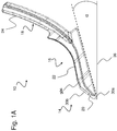
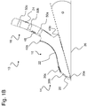
- the Figures 1A and 1B show the share point 10 according to the invention in a side view and in a sectional view.
- the share tip 10 comprises three areas.
- a first region 14 has a cutting edge 20, which is arranged at a free end in the longitudinal extension direction of the blade tip 10.
- the cutting edge 20 represents the narrowest portion of the blade tip 10 and has in the FIG. 1 a width between 20 mm to 30 mm, preferably 25 mm.
- the first region 14 and thus also the cutting edge 20 form a wedge-shaped form and enclose an angle between 25 ° and 45 °.
- the wedge-shaped shape of the first region 14 allows the coulter tip to more easily penetrate the soil during the tillage process.
- a second region 16 adjoins the first region 14 in the longitudinal direction of the blade tip 10 and is arranged downstream of this.
- the second region 16 has a running surface 22.
- the tread 22 may be at least partially arcuate and has a radius between 80 mm and 120 mm lock in. Preferably, the radius may be 100 mm.
- the second region 16 terminates with an elevation at the end of the at least partially curved running surface 22 on the front side of the blade tip 10, which elevation forms a first undercut 40a.
- In the first undercut 40a engages a corresponding end of the baffle 28 (not shown here) in the assembled state of the share tip 10 on a coulter handle 26 (see. FIG. 2 and FIG. 3 ) one.
- a second undercut 40b is provided, in which in the mounted state of the blade tip 10 on a coulter handle 26, the free end of the coulter handle 26 can lie correspondingly.
- the length of the first region 14 and the second region 16 of the blade tip 26 is in total 200 mm to 260 mm, preferably 230 mm. Thus, the sum of the lengths of the first region 14 and the second region 16 is at least five times the width of the cutting edge 20.
- the share tip 10 can be divided into a third area 18, which adjoins the second area 16 in the longitudinal extension direction of the blade tip 10.
- the third region 18 of the blade tip 10 forms a fastening region 24.
- the third region 18 formed as a fastening region 24 comprises at least three recesses 50a, 50b, 50c, which are spaced apart from one another. In each case at least three recesses 50a, 50b, 50c, a fastening means of the at least three attachment means (not shown here) are performed so that the share tip 10 at least partially on a share handle 26 (not shown here) by means of the third region 18 formed as a fastening region 24 ).
- the shape of the third region 18 designed as a fastening region 24 is arc-shaped at least in sections and includes a radius of 565 mm and 585 mm, preferably 575 mm.
- the third region 18 designed as a fastening region 24 has a width that is at least one fifth wider than the blade tip 10. Thereafter, the width of the third region 18 designed as a fastening region 24 measures between 30 mm and 40 mm, preferably 35 mm.
- the first region 14 and at least partially the second region 16 of the blade tip 10 wear elements 30 are assigned.
- a first wear element 30a is arranged in the first region 14 of the blade tip 20 and forms an undercut, wherein the undercut is formed corresponding to the shape of the cutting edge 20.
- the first wear element 30a is L-shaped.
- a second wear element 30b in the first region 14 of Scharspitze 10 provided.
- the second wear element 30b is formed as a plate and is flush with the first wear element 30a.
- the second wear element 30b may well also extend into the second region 16 of the blade tip.
- a third wear element 30c is provided at least in regions in the second region 16 of the blade tip 10.
- the third wear element 30c forms a small plate and, due to the at least partial arrangement in the second region 16 of the blade tip 10, is part of the at least partially curved running surface 22.
- the wear elements 30 are each formed from a wear-resistant material, preferably from a hard metal. Due to the use of wear elements 30, the share tip 10 is at least partially equipped with carbide.
- the blade tip 10 initially has a wedge-shaped widening with respect to a working direction, which encloses an angle of approximately 25 ° to 45 °, which in turn is followed by a wedge-shaped widening which encloses an angle between approximately 4 ° to 8 °, again followed by a conical taper which encloses an angle of between about 2 ° to 6 °.
- the wedge-shaped widenings and the conical taper extend in particular over the first region 14 and at least partially over the second region 16 of the blade tip 10.
- the conical taper is followed in particular by the at least partially arcuate running surface 22 of the second region 16 of the blade tip 10.
- the share tip 10 has on its rear side a clearance angle ⁇ in relation to a ground 36 to be processed.
- the clearance angle ⁇ includes an angle between 4 ° and 8 °, preferably an angle of 6 °. Due to the clearance angle ⁇ , the blade tip 10 is formed obliquely to the bottom 36 extending.
- FIGS. 2 and 3 show the share point 10 in a mounted state on a share handle 26 in different views and perspectives.
- a baffle 28 is provided on the front of the share handle 26 and a Scharschen 26 on the back of the share handle 26, which as a result form a share system 12.
- the skewer 26 has a width between 20 mm and 30 mm, preferably a width of 25 mm, and forms with respect to the ground to be machined 36 an angle between 7 ° to 13 °, preferably an angle of 10 °, ie the skewer 26 is bent with respect to the ground 36 to be machined.
- the share handle 26 has at least two recesses into which a fixing unit 38 for connecting the share handle 26 to a frame of an agricultural machine can be fixed.
- the baffle 28 is formed corresponding to the shape of the coulter handle 26 and arranged on the front of the coulter stick 26.
- the baffle 28 encloses an angle between 100 ° and 108 °, preferably an angle between 104 ° with respect to the ground 36 to be processed.
- At least one receiving unit 44 at least partially receives the handle arm 26 and ensures alignment of the guide plate 28 during assembly on the handle arm 26.
- the width of the at least one receiving unit 44 corresponds to the width of Scharstiels 26 and is thus between 20 mm and 30 mm, preferably 25 mm wide.
- At least one latching lug 46 is provided at the opposite end of the at least one receiving unit 44, which in the assembled state can engage in a corresponding opening formed by a groove 48 of the third area 18 designed as a fastening area 24.
- the at least one detent 46 is formed as a square elevation.
- the sharpening tip 10 When the sharpening tip 10 is in the assembled state, it is fixed on at least a section of a front side of a share handle 26 via the third area 18, which is designed as a fastening area 24, by means of at least three fastening means 42a, 42b, 42c.
- the third region 18 designed as a fastening region 24 has at least three recesses 50a, 50b, 50c in the form of bores which are arranged at a distance from one another.
- a first fastener 42a and a second fastener 42b connect the share tip 10 to the coulter 26, while a third fastener 42c connects the coulter tip 10 and the baffle 28 to the coulter 26.
- the first fastening means 42a and the second fastening means 42b are arranged in the region of a free end of the coulter handle 26, while the third fastening means 42c is provided at the adjacent end of the third region 18 of the coulter tip 10 formed as a fastening region 24, ie the third region designed as a fastening region 24 18 is shaped such that the Fixing portion 24 formed third region 18 between baffle 28 and a coulter handle 26 is mountable.
- the at least three fastening means 42a, 42b, 42c are designed as screw connections, so that by means of the at least three fastening means 42a, 42b, 42c, an effective releasable connection between the blade tip 10, the guide plate 28 and the skewer 26 is effected.
- the baffle 28 also ensures an overlap of the at least three fastening means 42a, 42b, 42c.
- the at least three fastening means 42a, 42b, 42c are protected against wear and contamination, ie the guide plate 28 extends over the third region 18 designed as a fastening region 24.
- the Scharschreiben 34 includes at least one receptacle which extends continuously along the longitudinal direction of the Scharschreibens 34.
- the at least receiving the Scharschreibens 34 corresponds to the width of the share handle 26 and serves to receive the share handle 26 at least in sections. Due to this, the shape of the coulter back 34, in particular its at least one receptacle, corresponding to the shape of the coulter handle 26 is formed.
- the Scharschreiben 34 comprises on its rear side at least one channel (not shown here), which extends along the longitudinal direction of the Scharschreibens 34.
- the at least one channel By means of the at least one channel, granular and / or liquid material, such as fertilizer, is deposited in the soil 34 to be processed.
- the Scharschreiben 34 is fixed by means of two laterally arranged further attachment means on the share handle 26, so that between the Scharschreiben 34 and the share handle 26 an acting releasable connection is formed.
- the two laterally arranged further fastening means are each guided by two laterally arranged recesses of the Scharschreibens 34 and the share handle 26 and then fixed.
- the FIG. 4 shows the baffle 28 in a perspective view.
- the baffle 28 comprises at one end an at least receiving unit 44, wherein the width of the at least one receiving unit 44 corresponds to a width of the handle arm 26. Thereafter, the at least one receiving unit 44 between 20 mm and 30 mm, preferably 25 mm wide.
- the at least one receiving unit 44 can rest in the assembled state on the front of the handle arm 26.
- at least one locking lug 46 is provided, which in the mounted state can engage in a corresponding opening in the form of a groove 48 of the third region 18 designed as a fastening region 24.
- the at least one detent 46 is formed as a square elevation.
Priority Applications (1)
| Application Number | Priority Date | Filing Date | Title |
|---|---|---|---|
| EP16166003.0A EP3235358B1 (fr) | 2016-04-19 | 2016-04-19 | Pointe de bande destinée à être utilisée dans un système de soc pour le traitement du sol |
Applications Claiming Priority (1)
| Application Number | Priority Date | Filing Date | Title |
|---|---|---|---|
| EP16166003.0A EP3235358B1 (fr) | 2016-04-19 | 2016-04-19 | Pointe de bande destinée à être utilisée dans un système de soc pour le traitement du sol |
Publications (2)
| Publication Number | Publication Date |
|---|---|
| EP3235358A1 true EP3235358A1 (fr) | 2017-10-25 |
| EP3235358B1 EP3235358B1 (fr) | 2020-03-18 |
Family
ID=55759560
Family Applications (1)
| Application Number | Title | Priority Date | Filing Date |
|---|---|---|---|
| EP16166003.0A Active EP3235358B1 (fr) | 2016-04-19 | 2016-04-19 | Pointe de bande destinée à être utilisée dans un système de soc pour le traitement du sol |
Country Status (1)
| Country | Link |
|---|---|
| EP (1) | EP3235358B1 (fr) |
Cited By (2)
| Publication number | Priority date | Publication date | Assignee | Title |
|---|---|---|---|---|
| EP3571905A1 (fr) * | 2018-05-22 | 2019-11-27 | Horsch Maschinen GmbH | Système de soc et pointe de soc destinés à être utilisés dans un système de soc pour le traitement du sol |
| EP3760019A1 (fr) * | 2019-07-02 | 2021-01-06 | BOEHLERIT GmbH & Co.KG. | Socs pour un appareil de traitement du sol |
Citations (6)
| Publication number | Priority date | Publication date | Assignee | Title |
|---|---|---|---|---|
| EP0222930A1 (fr) | 1985-11-22 | 1987-05-27 | Franz Kirchberger | Sous-soleuse |
| DE4022156C2 (de) | 1990-05-31 | 1999-01-07 | Otto Gruebl | Gerät zur Vorbereitung des Bodens für eine Reihensaat |
| DE102013102420A1 (de) | 2013-03-11 | 2014-09-11 | Betek Gmbh & Co. Kg | Scharspitze bzw. Werkzeugkombination mit einer Scharspitze |
| DE202014010340U1 (de) | 2014-11-13 | 2015-04-29 | Betek Gmbh & Co. Kg | Scharspitze bzw. Werkzeugkombination mit einer Scharspitze |
| DE202014010341U1 (de) | 2014-11-13 | 2015-04-29 | Betek Gmbh & Co. Kg | Leitelement bzw. Werkzeugkombination mit einem Leitelement |
| DE102011102053B4 (de) | 2011-05-19 | 2015-07-30 | Lemken Gmbh & Co. Kg | Schar |
Family Cites Families (2)
| Publication number | Priority date | Publication date | Assignee | Title |
|---|---|---|---|---|
| AT501965B1 (de) * | 2005-05-17 | 2007-04-15 | Vogel & Noot Landmaschinen Gmb | Grubberzinken sowie scharspitze hierfür |
| FR2911042B3 (fr) * | 2007-01-10 | 2009-03-20 | Kuhn Huard S A Sa | Outil de travail comportant un dispositif d'appui et machine de travail du sol equipee d'un tel outil |
-
2016
- 2016-04-19 EP EP16166003.0A patent/EP3235358B1/fr active Active
Patent Citations (6)
| Publication number | Priority date | Publication date | Assignee | Title |
|---|---|---|---|---|
| EP0222930A1 (fr) | 1985-11-22 | 1987-05-27 | Franz Kirchberger | Sous-soleuse |
| DE4022156C2 (de) | 1990-05-31 | 1999-01-07 | Otto Gruebl | Gerät zur Vorbereitung des Bodens für eine Reihensaat |
| DE102011102053B4 (de) | 2011-05-19 | 2015-07-30 | Lemken Gmbh & Co. Kg | Schar |
| DE102013102420A1 (de) | 2013-03-11 | 2014-09-11 | Betek Gmbh & Co. Kg | Scharspitze bzw. Werkzeugkombination mit einer Scharspitze |
| DE202014010340U1 (de) | 2014-11-13 | 2015-04-29 | Betek Gmbh & Co. Kg | Scharspitze bzw. Werkzeugkombination mit einer Scharspitze |
| DE202014010341U1 (de) | 2014-11-13 | 2015-04-29 | Betek Gmbh & Co. Kg | Leitelement bzw. Werkzeugkombination mit einem Leitelement |
Cited By (3)
| Publication number | Priority date | Publication date | Assignee | Title |
|---|---|---|---|---|
| EP3571905A1 (fr) * | 2018-05-22 | 2019-11-27 | Horsch Maschinen GmbH | Système de soc et pointe de soc destinés à être utilisés dans un système de soc pour le traitement du sol |
| EP3760019A1 (fr) * | 2019-07-02 | 2021-01-06 | BOEHLERIT GmbH & Co.KG. | Socs pour un appareil de traitement du sol |
| US11582893B2 (en) | 2019-07-02 | 2023-02-21 | Boehlerit Gmbh & Co. Kg. | Share for a soil cultivation implement |
Also Published As
| Publication number | Publication date |
|---|---|
| EP3235358B1 (fr) | 2020-03-18 |
Similar Documents
| Publication | Publication Date | Title |
|---|---|---|
| DE60037458T3 (de) | Landwirtschaftliches Gerät | |
| EP3079453B1 (fr) | Système d'outils | |
| EP3753383B1 (fr) | Élément de coupe | |
| EP3837934B1 (fr) | Dispositif de travail de sol destiné au travail agricole de la terre | |
| DE3628910A1 (de) | Zinken fuer bodenbearbeitungsgeraete mit fluegelschar | |
| EP3235358B1 (fr) | Pointe de bande destinée à être utilisée dans un système de soc pour le traitement du sol | |
| EP3818793A1 (fr) | Bande coupante et outil combiné doté d'une bande coupante ainsi que machine de traitement du sol agricole | |
| EP3331339B1 (fr) | Soc de cultivateur vissé par l'arrière | |
| EP3172951B1 (fr) | Outil de traitement de sol | |
| DE2514177C3 (de) | Aufreißer | |
| EP3760019B1 (fr) | Socs pour un appareil de traitement du sol | |
| EP1504639A1 (fr) | Outil d'ameublissement du sol avec système d'échange rapide | |
| EP0217387B1 (fr) | Soc de semoir | |
| DE19620292B4 (de) | Schar zum pflanzenschonenden Einbringen von Flüssigkeiten in den Boden | |
| DE102007005649A1 (de) | Grubberschar mit Zusatzvorrichtung | |
| EP1872643B1 (fr) | Dent de sacrificateur doté d'un support de soc | |
| EP3571905B1 (fr) | Système de soc et pointe de soc destinés à être utilisés dans un système de soc pour le traitement du sol | |
| EP0170835A1 (fr) | Charrue | |
| DE102010035566B4 (de) | Hohlzinken für ein Bodenbearbeitungsgerät | |
| EP4356702A1 (fr) | Soc de binage | |
| EP3225088B1 (fr) | Outil de traitement de sol | |
| DE10014155A1 (de) | Zinken mit Schar und Leitblech | |
| EP4356703A1 (fr) | Soc de hachage | |
| DE102021119921A1 (de) | Hackschar, Stiel, Werkzeuganordnung für eine Landmaschine und Landmaschine | |
| DE102006011202B3 (de) | Pflugschar |
Legal Events
| Date | Code | Title | Description |
|---|---|---|---|
| PUAI | Public reference made under article 153(3) epc to a published international application that has entered the european phase |
Free format text: ORIGINAL CODE: 0009012 |
|
| STAA | Information on the status of an ep patent application or granted ep patent |
Free format text: STATUS: THE APPLICATION HAS BEEN PUBLISHED |
|
| AK | Designated contracting states |
Kind code of ref document: A1 Designated state(s): AL AT BE BG CH CY CZ DE DK EE ES FI FR GB GR HR HU IE IS IT LI LT LU LV MC MK MT NL NO PL PT RO RS SE SI SK SM TR |
|
| AX | Request for extension of the european patent |
Extension state: BA ME |
|
| STAA | Information on the status of an ep patent application or granted ep patent |
Free format text: STATUS: REQUEST FOR EXAMINATION WAS MADE |
|
| 17P | Request for examination filed |
Effective date: 20171025 |
|
| RBV | Designated contracting states (corrected) |
Designated state(s): AL AT BE BG CH CY CZ DE DK EE ES FI FR GB GR HR HU IE IS IT LI LT LU LV MC MK MT NL NO PL PT RO RS SE SI SK SM TR |
|
| STAA | Information on the status of an ep patent application or granted ep patent |
Free format text: STATUS: EXAMINATION IS IN PROGRESS |
|
| 17Q | First examination report despatched |
Effective date: 20180323 |
|
| GRAP | Despatch of communication of intention to grant a patent |
Free format text: ORIGINAL CODE: EPIDOSNIGR1 |
|
| STAA | Information on the status of an ep patent application or granted ep patent |
Free format text: STATUS: GRANT OF PATENT IS INTENDED |
|
| GRAJ | Information related to disapproval of communication of intention to grant by the applicant or resumption of examination proceedings by the epo deleted |
Free format text: ORIGINAL CODE: EPIDOSDIGR1 |
|
| STAA | Information on the status of an ep patent application or granted ep patent |
Free format text: STATUS: EXAMINATION IS IN PROGRESS |
|
| INTG | Intention to grant announced |
Effective date: 20190904 |
|
| GRAP | Despatch of communication of intention to grant a patent |
Free format text: ORIGINAL CODE: EPIDOSNIGR1 |
|
| STAA | Information on the status of an ep patent application or granted ep patent |
Free format text: STATUS: GRANT OF PATENT IS INTENDED |
|
| INTC | Intention to grant announced (deleted) | ||
| INTG | Intention to grant announced |
Effective date: 20191010 |
|
| GRAS | Grant fee paid |
Free format text: ORIGINAL CODE: EPIDOSNIGR3 |
|
| GRAA | (expected) grant |
Free format text: ORIGINAL CODE: 0009210 |
|
| STAA | Information on the status of an ep patent application or granted ep patent |
Free format text: STATUS: THE PATENT HAS BEEN GRANTED |
|
| AK | Designated contracting states |
Kind code of ref document: B1 Designated state(s): AL AT BE BG CH CY CZ DE DK EE ES FI FR GB GR HR HU IE IS IT LI LT LU LV MC MK MT NL NO PL PT RO RS SE SI SK SM TR |
|
| REG | Reference to a national code |
Ref country code: GB Ref legal event code: FG4D Free format text: NOT ENGLISH |
|
| REG | Reference to a national code |
Ref country code: DE Ref legal event code: R096 Ref document number: 502016009166 Country of ref document: DE |
|
| REG | Reference to a national code |
Ref country code: AT Ref legal event code: REF Ref document number: 1244816 Country of ref document: AT Kind code of ref document: T Effective date: 20200415 Ref country code: IE Ref legal event code: FG4D Free format text: LANGUAGE OF EP DOCUMENT: GERMAN |
|
| PG25 | Lapsed in a contracting state [announced via postgrant information from national office to epo] |
Ref country code: NO Free format text: LAPSE BECAUSE OF FAILURE TO SUBMIT A TRANSLATION OF THE DESCRIPTION OR TO PAY THE FEE WITHIN THE PRESCRIBED TIME-LIMIT Effective date: 20200618 Ref country code: FI Free format text: LAPSE BECAUSE OF FAILURE TO SUBMIT A TRANSLATION OF THE DESCRIPTION OR TO PAY THE FEE WITHIN THE PRESCRIBED TIME-LIMIT Effective date: 20200318 Ref country code: RS Free format text: LAPSE BECAUSE OF FAILURE TO SUBMIT A TRANSLATION OF THE DESCRIPTION OR TO PAY THE FEE WITHIN THE PRESCRIBED TIME-LIMIT Effective date: 20200318 |
|
| REG | Reference to a national code |
Ref country code: NL Ref legal event code: MP Effective date: 20200318 |
|
| PG25 | Lapsed in a contracting state [announced via postgrant information from national office to epo] |
Ref country code: GR Free format text: LAPSE BECAUSE OF FAILURE TO SUBMIT A TRANSLATION OF THE DESCRIPTION OR TO PAY THE FEE WITHIN THE PRESCRIBED TIME-LIMIT Effective date: 20200619 Ref country code: HR Free format text: LAPSE BECAUSE OF FAILURE TO SUBMIT A TRANSLATION OF THE DESCRIPTION OR TO PAY THE FEE WITHIN THE PRESCRIBED TIME-LIMIT Effective date: 20200318 Ref country code: LV Free format text: LAPSE BECAUSE OF FAILURE TO SUBMIT A TRANSLATION OF THE DESCRIPTION OR TO PAY THE FEE WITHIN THE PRESCRIBED TIME-LIMIT Effective date: 20200318 Ref country code: SE Free format text: LAPSE BECAUSE OF FAILURE TO SUBMIT A TRANSLATION OF THE DESCRIPTION OR TO PAY THE FEE WITHIN THE PRESCRIBED TIME-LIMIT Effective date: 20200318 Ref country code: BG Free format text: LAPSE BECAUSE OF FAILURE TO SUBMIT A TRANSLATION OF THE DESCRIPTION OR TO PAY THE FEE WITHIN THE PRESCRIBED TIME-LIMIT Effective date: 20200618 |
|
| REG | Reference to a national code |
Ref country code: LT Ref legal event code: MG4D |
|
| PG25 | Lapsed in a contracting state [announced via postgrant information from national office to epo] |
Ref country code: NL Free format text: LAPSE BECAUSE OF FAILURE TO SUBMIT A TRANSLATION OF THE DESCRIPTION OR TO PAY THE FEE WITHIN THE PRESCRIBED TIME-LIMIT Effective date: 20200318 |
|
| PG25 | Lapsed in a contracting state [announced via postgrant information from national office to epo] |
Ref country code: PT Free format text: LAPSE BECAUSE OF FAILURE TO SUBMIT A TRANSLATION OF THE DESCRIPTION OR TO PAY THE FEE WITHIN THE PRESCRIBED TIME-LIMIT Effective date: 20200812 Ref country code: EE Free format text: LAPSE BECAUSE OF FAILURE TO SUBMIT A TRANSLATION OF THE DESCRIPTION OR TO PAY THE FEE WITHIN THE PRESCRIBED TIME-LIMIT Effective date: 20200318 Ref country code: SM Free format text: LAPSE BECAUSE OF FAILURE TO SUBMIT A TRANSLATION OF THE DESCRIPTION OR TO PAY THE FEE WITHIN THE PRESCRIBED TIME-LIMIT Effective date: 20200318 Ref country code: LT Free format text: LAPSE BECAUSE OF FAILURE TO SUBMIT A TRANSLATION OF THE DESCRIPTION OR TO PAY THE FEE WITHIN THE PRESCRIBED TIME-LIMIT Effective date: 20200318 Ref country code: RO Free format text: LAPSE BECAUSE OF FAILURE TO SUBMIT A TRANSLATION OF THE DESCRIPTION OR TO PAY THE FEE WITHIN THE PRESCRIBED TIME-LIMIT Effective date: 20200318 Ref country code: CZ Free format text: LAPSE BECAUSE OF FAILURE TO SUBMIT A TRANSLATION OF THE DESCRIPTION OR TO PAY THE FEE WITHIN THE PRESCRIBED TIME-LIMIT Effective date: 20200318 Ref country code: IS Free format text: LAPSE BECAUSE OF FAILURE TO SUBMIT A TRANSLATION OF THE DESCRIPTION OR TO PAY THE FEE WITHIN THE PRESCRIBED TIME-LIMIT Effective date: 20200718 Ref country code: SK Free format text: LAPSE BECAUSE OF FAILURE TO SUBMIT A TRANSLATION OF THE DESCRIPTION OR TO PAY THE FEE WITHIN THE PRESCRIBED TIME-LIMIT Effective date: 20200318 |
|
| REG | Reference to a national code |
Ref country code: CH Ref legal event code: PL |
|
| REG | Reference to a national code |
Ref country code: DE Ref legal event code: R097 Ref document number: 502016009166 Country of ref document: DE |
|
| PG25 | Lapsed in a contracting state [announced via postgrant information from national office to epo] |
Ref country code: MC Free format text: LAPSE BECAUSE OF FAILURE TO SUBMIT A TRANSLATION OF THE DESCRIPTION OR TO PAY THE FEE WITHIN THE PRESCRIBED TIME-LIMIT Effective date: 20200318 |
|
| PLBE | No opposition filed within time limit |
Free format text: ORIGINAL CODE: 0009261 |
|
| STAA | Information on the status of an ep patent application or granted ep patent |
Free format text: STATUS: NO OPPOSITION FILED WITHIN TIME LIMIT |
|
| PG25 | Lapsed in a contracting state [announced via postgrant information from national office to epo] |
Ref country code: IT Free format text: LAPSE BECAUSE OF FAILURE TO SUBMIT A TRANSLATION OF THE DESCRIPTION OR TO PAY THE FEE WITHIN THE PRESCRIBED TIME-LIMIT Effective date: 20200318 Ref country code: CH Free format text: LAPSE BECAUSE OF NON-PAYMENT OF DUE FEES Effective date: 20200430 Ref country code: ES Free format text: LAPSE BECAUSE OF FAILURE TO SUBMIT A TRANSLATION OF THE DESCRIPTION OR TO PAY THE FEE WITHIN THE PRESCRIBED TIME-LIMIT Effective date: 20200318 Ref country code: DK Free format text: LAPSE BECAUSE OF FAILURE TO SUBMIT A TRANSLATION OF THE DESCRIPTION OR TO PAY THE FEE WITHIN THE PRESCRIBED TIME-LIMIT Effective date: 20200318 Ref country code: LI Free format text: LAPSE BECAUSE OF NON-PAYMENT OF DUE FEES Effective date: 20200430 Ref country code: LU Free format text: LAPSE BECAUSE OF NON-PAYMENT OF DUE FEES Effective date: 20200419 |
|
| REG | Reference to a national code |
Ref country code: BE Ref legal event code: MM Effective date: 20200430 |
|
| 26N | No opposition filed |
Effective date: 20201221 |
|
| PG25 | Lapsed in a contracting state [announced via postgrant information from national office to epo] |
Ref country code: BE Free format text: LAPSE BECAUSE OF NON-PAYMENT OF DUE FEES Effective date: 20200430 Ref country code: PL Free format text: LAPSE BECAUSE OF FAILURE TO SUBMIT A TRANSLATION OF THE DESCRIPTION OR TO PAY THE FEE WITHIN THE PRESCRIBED TIME-LIMIT Effective date: 20200318 |
|
| GBPC | Gb: european patent ceased through non-payment of renewal fee |
Effective date: 20200618 |
|
| PG25 | Lapsed in a contracting state [announced via postgrant information from national office to epo] |
Ref country code: GB Free format text: LAPSE BECAUSE OF NON-PAYMENT OF DUE FEES Effective date: 20200618 Ref country code: IE Free format text: LAPSE BECAUSE OF NON-PAYMENT OF DUE FEES Effective date: 20200419 Ref country code: FR Free format text: LAPSE BECAUSE OF NON-PAYMENT OF DUE FEES Effective date: 20200518 |
|
| PG25 | Lapsed in a contracting state [announced via postgrant information from national office to epo] |
Ref country code: SI Free format text: LAPSE BECAUSE OF FAILURE TO SUBMIT A TRANSLATION OF THE DESCRIPTION OR TO PAY THE FEE WITHIN THE PRESCRIBED TIME-LIMIT Effective date: 20200318 |
|
| PG25 | Lapsed in a contracting state [announced via postgrant information from national office to epo] |
Ref country code: TR Free format text: LAPSE BECAUSE OF FAILURE TO SUBMIT A TRANSLATION OF THE DESCRIPTION OR TO PAY THE FEE WITHIN THE PRESCRIBED TIME-LIMIT Effective date: 20200318 Ref country code: MT Free format text: LAPSE BECAUSE OF FAILURE TO SUBMIT A TRANSLATION OF THE DESCRIPTION OR TO PAY THE FEE WITHIN THE PRESCRIBED TIME-LIMIT Effective date: 20200318 Ref country code: CY Free format text: LAPSE BECAUSE OF FAILURE TO SUBMIT A TRANSLATION OF THE DESCRIPTION OR TO PAY THE FEE WITHIN THE PRESCRIBED TIME-LIMIT Effective date: 20200318 |
|
| REG | Reference to a national code |
Ref country code: AT Ref legal event code: MM01 Ref document number: 1244816 Country of ref document: AT Kind code of ref document: T Effective date: 20210419 |
|
| PG25 | Lapsed in a contracting state [announced via postgrant information from national office to epo] |
Ref country code: MK Free format text: LAPSE BECAUSE OF FAILURE TO SUBMIT A TRANSLATION OF THE DESCRIPTION OR TO PAY THE FEE WITHIN THE PRESCRIBED TIME-LIMIT Effective date: 20200318 Ref country code: AL Free format text: LAPSE BECAUSE OF FAILURE TO SUBMIT A TRANSLATION OF THE DESCRIPTION OR TO PAY THE FEE WITHIN THE PRESCRIBED TIME-LIMIT Effective date: 20200318 |
|
| PG25 | Lapsed in a contracting state [announced via postgrant information from national office to epo] |
Ref country code: AT Free format text: LAPSE BECAUSE OF NON-PAYMENT OF DUE FEES Effective date: 20210419 |
|
| PGFP | Annual fee paid to national office [announced via postgrant information from national office to epo] |
Ref country code: DE Payment date: 20230418 Year of fee payment: 8 |