EP2804790B1 - Einheit zur befestigung einer wischervorrichtung für ein fahrzeug - Google Patents
Einheit zur befestigung einer wischervorrichtung für ein fahrzeug Download PDFInfo
- Publication number
- EP2804790B1 EP2804790B1 EP12758420.9A EP12758420A EP2804790B1 EP 2804790 B1 EP2804790 B1 EP 2804790B1 EP 12758420 A EP12758420 A EP 12758420A EP 2804790 B1 EP2804790 B1 EP 2804790B1
- Authority
- EP
- European Patent Office
- Prior art keywords
- pivot
- support element
- tenon
- unit according
- fixing
- Prior art date
- Legal status (The legal status is an assumption and is not a legal conclusion. Google has not performed a legal analysis and makes no representation as to the accuracy of the status listed.)
- Not-in-force
Links
- 229920003023 plastic Polymers 0.000 claims description 9
- 239000004033 plastic Substances 0.000 claims description 9
- 239000000463 material Substances 0.000 claims description 8
- 238000003466 welding Methods 0.000 claims description 8
- 238000001125 extrusion Methods 0.000 claims description 7
- 238000002347 injection Methods 0.000 claims description 7
- 239000007924 injection Substances 0.000 claims description 7
- 239000011368 organic material Substances 0.000 claims description 6
- 238000005476 soldering Methods 0.000 claims description 5
- 229910000838 Al alloy Inorganic materials 0.000 claims description 4
- 238000002788 crimping Methods 0.000 claims description 4
- 229910052751 metal Inorganic materials 0.000 claims description 4
- 229910001297 Zn alloy Inorganic materials 0.000 claims description 3
- 239000002184 metal Substances 0.000 claims description 3
- 238000000465 moulding Methods 0.000 claims description 3
- 229910000861 Mg alloy Inorganic materials 0.000 claims description 2
- 229910000831 Steel Inorganic materials 0.000 claims description 2
- 238000005516 engineering process Methods 0.000 claims description 2
- 238000005245 sintering Methods 0.000 claims description 2
- 239000010959 steel Substances 0.000 claims description 2
- 239000000243 solution Substances 0.000 description 13
- 238000000034 method Methods 0.000 description 12
- 238000004519 manufacturing process Methods 0.000 description 5
- 238000012360 testing method Methods 0.000 description 4
- 208000027418 Wounds and injury Diseases 0.000 description 3
- 230000006378 damage Effects 0.000 description 3
- 208000014674 injury Diseases 0.000 description 3
- 238000003825 pressing Methods 0.000 description 3
- 229910000881 Cu alloy Inorganic materials 0.000 description 2
- 238000004026 adhesive bonding Methods 0.000 description 2
- 230000002452 interceptive effect Effects 0.000 description 2
- 230000000284 resting effect Effects 0.000 description 2
- 238000010008 shearing Methods 0.000 description 2
- FYYHWMGAXLPEAU-UHFFFAOYSA-N Magnesium Chemical compound [Mg] FYYHWMGAXLPEAU-UHFFFAOYSA-N 0.000 description 1
- HCHKCACWOHOZIP-UHFFFAOYSA-N Zinc Chemical compound [Zn] HCHKCACWOHOZIP-UHFFFAOYSA-N 0.000 description 1
- 239000004411 aluminium Substances 0.000 description 1
- 229910052782 aluminium Inorganic materials 0.000 description 1
- XAGFODPZIPBFFR-UHFFFAOYSA-N aluminium Chemical compound [Al] XAGFODPZIPBFFR-UHFFFAOYSA-N 0.000 description 1
- 238000004364 calculation method Methods 0.000 description 1
- 229920002678 cellulose Polymers 0.000 description 1
- 239000001913 cellulose Substances 0.000 description 1
- 230000000694 effects Effects 0.000 description 1
- 239000004744 fabric Substances 0.000 description 1
- 230000002349 favourable effect Effects 0.000 description 1
- 239000003292 glue Substances 0.000 description 1
- 230000001788 irregular Effects 0.000 description 1
- 229910052749 magnesium Inorganic materials 0.000 description 1
- 239000011777 magnesium Substances 0.000 description 1
- 229910001092 metal group alloy Inorganic materials 0.000 description 1
- 239000007769 metal material Substances 0.000 description 1
- 238000004806 packaging method and process Methods 0.000 description 1
- 230000035945 sensitivity Effects 0.000 description 1
- 229910000679 solder Inorganic materials 0.000 description 1
- 239000011701 zinc Substances 0.000 description 1
- 229910052725 zinc Inorganic materials 0.000 description 1
Images


Classifications
-
- B—PERFORMING OPERATIONS; TRANSPORTING
- B60—VEHICLES IN GENERAL
- B60S—SERVICING, CLEANING, REPAIRING, SUPPORTING, LIFTING, OR MANOEUVRING OF VEHICLES, NOT OTHERWISE PROVIDED FOR
- B60S1/00—Cleaning of vehicles
- B60S1/02—Cleaning windscreens, windows or optical devices
- B60S1/04—Wipers or the like, e.g. scrapers
- B60S1/32—Wipers or the like, e.g. scrapers characterised by constructional features of wiper blade arms or blades
- B60S1/34—Wiper arms; Mountings therefor
-
- B—PERFORMING OPERATIONS; TRANSPORTING
- B60—VEHICLES IN GENERAL
- B60S—SERVICING, CLEANING, REPAIRING, SUPPORTING, LIFTING, OR MANOEUVRING OF VEHICLES, NOT OTHERWISE PROVIDED FOR
- B60S1/00—Cleaning of vehicles
- B60S1/02—Cleaning windscreens, windows or optical devices
- B60S1/04—Wipers or the like, e.g. scrapers
- B60S1/0413—Modular wiper assembly
- B60S1/0422—Modular wiper assembly having a separate transverse element
- B60S1/0425—Modular wiper assembly having a separate transverse element characterised by the attachment of the wiper shaft holders to the transverse element
-
- B—PERFORMING OPERATIONS; TRANSPORTING
- B60—VEHICLES IN GENERAL
- B60S—SERVICING, CLEANING, REPAIRING, SUPPORTING, LIFTING, OR MANOEUVRING OF VEHICLES, NOT OTHERWISE PROVIDED FOR
- B60S1/00—Cleaning of vehicles
- B60S1/02—Cleaning windscreens, windows or optical devices
- B60S1/04—Wipers or the like, e.g. scrapers
- B60S1/0413—Modular wiper assembly
- B60S1/0422—Modular wiper assembly having a separate transverse element
- B60S1/0427—Modular wiper assembly having a separate transverse element characterised by the attachment of the wiper motor holder to the transverse element
-
- B—PERFORMING OPERATIONS; TRANSPORTING
- B60—VEHICLES IN GENERAL
- B60S—SERVICING, CLEANING, REPAIRING, SUPPORTING, LIFTING, OR MANOEUVRING OF VEHICLES, NOT OTHERWISE PROVIDED FOR
- B60S1/00—Cleaning of vehicles
- B60S1/02—Cleaning windscreens, windows or optical devices
- B60S1/04—Wipers or the like, e.g. scrapers
- B60S1/0488—Wiper arrangement for crash protection or impact absorption
Definitions
- the object of the invention is a unit for fixing an automotive wiper device, comprising at least one pivot housing for setting the shaft for fixing the automotive wiper arm.
- the invention is used in the automotive industry, especially for the assembly of wipers in passenger cars and trucks.
- the wiper arms are fixed to the so-called shaft (axle).
- the shaft rotates alternately in opposite directions within a specific angle and thus makes the wiper arm move over the car windshield and then return to the home position.
- the wiper systems are driven by electric motors.
- the electric motor uses a system of suitable external devices, pull rods etc. to drive two or more shafts (axles), to which the wipers are fixed.
- pivot housings provided with a part provided for fixing them to the car by means of a grommet. Between two pivot housings, a support element is fitted, to which the wiper motor, the pull rod set etc. are fixed.
- fixing system has been disclosed in the international patent application no PCT/EP2008/064497 .
- pivot housings 3, 4 comprise grommets 5, 6, which are used to fix them to a car.
- Shafts 7, 8 which are set in the pivot housings are provided for fixing the wiper arms on them.
- Pivot housings 3, 4 are interconnected by means of a specially profiled tube 2, to which the motor and pull cord set are fixed.
- pivot housing design unique for a given vehicle, makes it also necessary to use special custom-designed tools for the production of pivot housings and then to test their strength in multi-week testing programmes. It is naturally unfavourable for the car manufacturers and their vendors since it causes additional costs, makes the car development stage longer and makes it impossible to adjust the arm position without interfering with the tools for the production of pivot housings.
- the aim of the present invention is to provide a universal set for fixing the automotive wiper device, that is, a device which would be suitable for use in various types and models of cars, and in which the distance of the assembly point of the shaft in the pivot housing from the assembly point of the entire unit to the car and the mutual distance of the shafts from each other and their inclination against the automotive windshield would be freely set, according to the specific characteristics of the given car model, without having to develop new tools for the production of the pivot housing.
- Another aim of the present invention is to provide a universal set for fixing the automotive wiper device, which would be safe for pedestrians / pedestrian participants of an accident.
- a unit for fixing an automotive wiper device comprising at least one pivot housing for setting the automotive wiper arm fixing shaft, is characterised in that said pivot housing is suspended through a pivot tenon on a support element, the ends of the support element being provided with grommets for fixing the support element to the car.
- said unit comprises one, two or three said pivot housings, each of which is suspended through a pivot tenon on said support element.
- said pivot housing and said pivot tenon are made of organic material, preferably by extrusion or injection, and are connected with each other by bonding, welding or by means of external elements, preferably a buckle, a rivet or a bolt.
- organic material used in the present description and in the patent claims, includes plastics as well as more and more frequently used organic recyclable materials, e.g., glued and pressed sawdust, cellulose, fabrics etc., which can be organic materials with properties sufficient for the current use although obtaining these properties in case of these materials is still too expensive.
- said pivot housing and said pivot tenon are made of an aluminium alloy, zinc alloy, magnesium alloy, steel, sintered material or made in the extrusion, injection, sintering, cold or hot moulding technology and are connected with each other by soldering, welding, bonding, creasing or connected by means of external elements, preferably a buckle, a rivet or a bolt.
- said pivot tenon comprises an element provided for setting the pivot housing in it and an element fixing the pivot tenon to the support element.
- said element is connected with said clamp element by means of cold plastic forming of metal sheets, soldering or welding.
- said support element has a specially shaped area provided for fixing said pivot tenon, said pivot tenon having an internal profile matched to fit the external profile of said support element in said area.
- said pivot tenon has projections at the ends of its internal profile.
- said pivot tenon has at least one protrusion or cavity on its internal profile, preferably an even number of protrusions or cavities.
- said pivot tenon is fixed on said support element by crimping the support element into it.
- said pivot tenon may be additionally glued, soldered or welded to said support element.
- said support element is a tube.
- said pivot housing on its inner surface has at least one rib, directed towards the centre of the pivot housing, and preferably two or more such ribs.
- said rib is preliminary sheared.
- said rib has a smaller dimension at the base connecting with the pivot housing and a bigger dimension above, and preferably it is additionally inclined around the axis of the shaft.
- said rib has an alternating cross section along its axis.
- said support element there are holes facilitating the positioning and fixing of said pivot tenon on said support element.
- the important advantage of the solution according to the invention is its universality. Owing to the fact, that fixing the pivot housing directly to the car has been abandoned and the pivot housing has instead been suspended on the support element (for example, a tube), which is fixed to the car through grommets - the distance between the point of fixing the shaft in the pivot housing and the point of fixing said grommets to the car is practically free to choose, without changing the support element (the tube) or interfering with other components of the wiper system.
- One, two, three or even more pivot housings - as needed - can be suspended on said support element and the distance between them can be freely adjusted.
- the pivot housing can be freely positioned by rotating it against the pivot tenon and also by rotating the pivot tenon against with support element. It practically allows the shaft to be freely positioned and, as a result, to adjust the position of the wiper arms to any automotive windshield.
- the other components (pivot housings, pivot tenons) and the way of suspending on the support element (the tube) remain unchanged. This allows standardisation of these elements and standardisation of tools used to fix assemble them. Custom-designed parts or tools are no longer always indispensable.
- the rib or ribs on the inner surface of the pivot housing allow ensuring protection of pedestrians / pedestrian participants of an accident.
- the typical, known in the prior art setting of the shaft location in the pivot housing by means of a bearing and a Seeger ring ensures, that the shaft retains its position under loads related to the regular use or servicing of a car, and in case of a collision - does not fall out of the pivot housing.
- the disadvantage of that setting is that it endangers a pedestrian in case of a collision with the car.
- the preliminarily sheared rib or ribs - ensures safety of a pedestrian who would hit the shaft from the above in case of an accident. If that happens, the rib or ribs are sheared by the impact force, whereas the shaft will fall inside the pivot housing without causing any injury to the pedestrian's body.
- the additional advantage of the preliminarily sheared ribs is that it is possible to measure the force required to insert bearings while assembling each pivot housing, which then makes it possible to control the force which makes the shaft fall into the pivot housing.
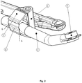
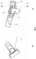
- Fig. 1 shows the embodiment of the unit for fixing the automotive wiper device according to the invention.
- two pivot housing 1 - pivot tenon 3 units are suspended on the support element 4 - in this case, a tube. Both elements of the support element 4 are provided with grommets 5, provided to fix the wiper device to the car.
- the areas 8 of the support element 4, to which the pivot tenon 3 is fixed have a proper shape, adjusted to the inner profile of the pivot tenon 3. This adjustment can be performed during the assembly of the support element 4 with the pivot tenon 3, without the need to perform additional procedures or operations of preliminary deformation of the support element 4 or to use additional connecting elements which is discussed in greater detail in the embodiment 4.
- the set shafts 2 are shown.
- the pivot tenons 3 are positioned at a desired angle against the tube 4, whereas the pivot housings 1 are positioned at a desired angle against the pivot tenons 3.
- a position of the shafts 2 proper for the given car model is obtained.
- the wiper motor unit 14 is also fixed. The mutual distance between the pivot housings can be adjusted while maintaining the geometry of the element 4. Such adjustment may take place independently of points of fixing the tube 4 to the car.
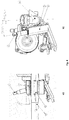
- Fig. 2 shows a close-up view of the pivot housing 1 and the pivot tenon 3 of the unit visible in fig. 1 .
- the pivot housing 1 and the pivot tenon 3 are made of plastics, by means of extrusion method.
- the inner surface of the pivot housing 1 has a polygonal cross section, but optionally it can be a circular cross section.
- the pivot housing 1 plays a role of a bearing due to good tribological properties of plastics.
- the cross section working with the bearing can be elliptical or irregular.
- the pivot housing 1 can be rotated against the pivot tenon 3 before them being glued or welded.
- two, three or more pivot housing 1 - pivot tenon 3 units can be suspended on the tube 4.
- Fig. 3 shows a general close-up view of another pivot housing 1 and the pivot tenon 3, similar to that of the unit visible in fig. 1 .
- the pivot housing 1 and the pivot tenon 3 are made of a profile of an aluminium alloy.
- good materials are e.g. other metal alloys, such as zinc, magnesium, sintered materials as well as organic materials formed in the process of extrusion, injection, cold or hot moulding.
- the inner surface of the pivot housing 1 has a shape of a cylinder with the rib 11.
- the purpose of the rib 11 is to increase the safety of pedestrians in case of an accident. It can also be used to determine the position favourable with regard to the load of slide sleeves, which more and more frequently replace slide bearings made of copper alloys or plastics. The role of the rib 11 is explained in greater detail in the example 4.
- the pivot housing 1 can be rotated against the pivot tenon 3 (angle alpha in fig. 4a ) before they are soldered, welded, glued or connected to each other by means of external elements: buckle, rivet, bolt.
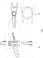
- Fig. 4a illustrates the way of determining the position of the pivot housing 1 against the pivot tenon 3
- fig. 4b illustrates the way of determining the position of the pivot tenon 3 against the support element 4.
- the pivot tenon 3 fixing is done on the support element 4, which is illustrated in fig. 4c .
- the support element in the shape of the tube 4 is fixed by pressing the support element 4 in the pivot tenon 3 ( crimping ), which is illustrated by fig. 4e .
- the area 8 of the tube 4, provided to fix the pivot tenon 3, is not pre-machined and the tube 4 obtains its shape, which is required to keep it in the pivot tenon 3 by impressing the shape of the pivot tenon 3 as a result of pressing the tube 4 inside with the pressure element 18.
- the support element 4 matches with the pivot tenon 3, which is facilitated by the protrusions 9.
- the structure of the protrusion 9 illustrated in fig. 4e makes it possible for a typical tube 4 to match with the pivot tenon 3 while forcing it into the pivot tenon 3 so as to make the protrusions 9 come in contact with the fixing element surface, which has been tested during the processes of such assembly performed so far.
- the height of said protrusions or cavities 9 may, for example, amount to 50% of the inner cross section of the pivot tenon 3, but it can also be smaller or bigger than that value and can depend on the quantity and the shape of said protrusions or cavities 9.
- the pivot tenon 3 visible in fig. 4c has projections 10 on the ends of its inner profile. These projections additionally prevent the support element 4 from sliding out of the pivot tenon 3.
- the holes 6 in the support element 4, made before forcing it into the pivot tenon 3, form, after forcing it into the pivot tenon 3, an additional protection against an off-set of the pivot tenon 3 along the axis of the element 19 of the pivot tenon 3, provided to fix it to the support element 4.
- Said holes 6 additionally take the degrees of freedom of the pivot tenon 3 in the axis of the element 19 of the pivot tenon provided to fix the pivot tenon to the support element 4.
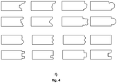
- the selected, preferable shapes of the pivot tenon 3 are shown in fig. 5 .
- the pivot tenons 3 are used, the inner profile of which has the shape corresponding to the shape of the tube 4 in the fixing area 8, which makes the pivot tenon 3 adjoin the tube 4 in the fixing area 8.
- Fig 5a illustrates the pivot tenon 3, which itself becomes an element tightening the support element 4.
- the support element 4 is not separated by the pivot tenon 3 from the pivot housing 1 but it can adjoin the pivot housing 1.
- Fig 5b illustrates the pivot tenon 3 to which the support element (the tube 4) is fixed obliquely from the bottom.
- Fig 5c illustrates the pivot tenon 3 in which the clamp element used to fix it with the pivot housing 1 is divided into two smaller fields (into two smaller surfaces).
- the advantage of such solution is avoiding internal stresses which occur in large area glue, solder or weld connections. Such stresses increase after forcing the fixing element into the pivot tenon 3 and dividing a large surface into two or more smaller ones reduces their negative impact on the connection between the tube 4 and the pivot tenon 3.
- Fig 5b illustrates the pivot tenon 3 to which the support element (the tube 4) is fixed obliquely from the side.
- Fig 5e shows profiles of the pivot tenons 3, optimised for the production in the extrusion process. These profiles are optimised with regard to the ratio of weight to the strength of the clamp required to convey assembly and operational stresses.
- the illustrated shapes allow minimising the deformations of the element 7 of the pivot tenon 3, used to fix it with the pivot housing 1.
- the pivot tenon 3 and the support element 4 can be connected by gluing, welding, soldering or other methods known to those skilled in the art, according to desired connection strength and loads which the connection must resist. It is preferable to avoid additional fasteners such as bolts, rivets, pins.
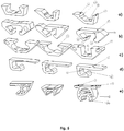
- Fig. 6 shows a close-up view of another example of the pivot housing 1 and the pivot tenon 3 fixed on the support tube 4.
- the pivot tenon 3 illustrated herein is made by the method of metal sheet cold plastic working (stamping) and welded to the support element 4.
- the pivot tenon 3 made in such a way can be welded, soldered or glued to the support element 4.
- the pivot housing 1 in the provided example plays a role of a bearing; therefore it is made of material with good tribological properties, for example plastics, copper alloy or other.
- the pivot housing 1 can also be made to cooperate with a bearing or many bearings; then it can be made of other materials, e.g. aluminium alloy or zinc alloy.
- the elements 7, 19 of the pivot tenon 3 and the pivot housing 1 can constitute a single, integrally formed part.
- the integrated pivot tenon 3 with the pivot housing 1 has been developed which can be made of metal or organic material (e.g. formed by injection or under pressure).
- Fig. 7 schematically shows the method of assembling the shaft 2 in the pivot housing 1 provided with the ribs 11 and the behaviour of the shaft 2 during the assembly process ( fig. 7a ), regular use ( fig. 7b ) and in case a pedestrian's or a passenger's body hits the shaft 2 (a road accident - fig. 7c ).
- the shaft 2 is fixed in the pivot housing 1 through the slide bearings 12 and secured with the Seeger ring 13, which ensures that the shaft 2 remains in its position under loads related to the regular use or service of the car, and in case of a body impact, e.g. a pedestrian's head, the head encounters smaller resistance as the shaft 2 falls out of the pivot housing 1 reducing the injuries being caused.
- a body impact e.g. a pedestrian's head
- This encounters smaller resistance as the shaft 2 falls out of the pivot housing 1 reducing the injuries being caused.
- This is preferable with regard to the standard tests of the pedestrians' protection and allows scoring more points, e.g. in the EURO NCAP tests.
- the ribs 11 are preliminarily sheared.
- ribs 11 will be further sheared by the bearing 12 while the shaft 2 will fall inside the pivot housing 1, transferring adequate energy and thus protecting the pedestrian's body from injuries.
- the advantage of using the pre-sheared rib 11 is the possibility, during the assembly, to measure the energy required to move the shaft 2 with the bearing 12 inside the pivot housing 1 as well as the force required to do that, which cannot be done by means of solutions known in the prior art (e.g. WO1998028164 ).
- Such solution can be employed also apart from the wiper system e.g. in automotive bumpers or automotive seats.
- the pivot housing 1 which is shown in the embodiment in fig. 3 has one rib 11. Alternatively, there can be more ribs 11.
- the ribs 11 should have a smaller dimension at the base connecting with the pivot housing 1 and a bigger one above, which facilitates shearing the rib 11 and protects from the unfavourable effect of the rib 11 being crushed between the bearing 12 and the pivot housing 1.
- the ribs 11 featuring such geometry are illustrated in fig. 8b .
- the ribs 11 can be inclined around the axis of the shaft 2 which is also shown in fig. 8b and even better shown in fig. 8a
- the profile of the ribs 11 (in cross-section) can alter along their axis.
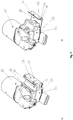
- Fig. 9 shows further two embodiments, wherein the pivot tenon 3 is integrated with the motor 14 of the wiper system.
- Such solution allows fixing the motor 14 on the support element 4 without having to use additional fixing parts (fasteners).
- the pivot tenon 3 is integrated with the case 16 of the motor gear, whereas in the embodiment shown in fig. 9b the pivot tenon 3 is integrated with the cover 17 of the motor gear case.
Landscapes
- Engineering & Computer Science (AREA)
- Mechanical Engineering (AREA)
- Pivots And Pivotal Connections (AREA)
- Connection Of Plates (AREA)
- Fluid-Damping Devices (AREA)
Claims (16)
- Einheit zur Befestigung einer Wischervorrichtung für ein Fahrzeug, aufweisend mindestens ein Schwenkgehäuse zum Einrichten des Fahrzeugwischerarmschafts, wobei das Schwenkgehäuse (1) über einen Schwenkzapfen (3) an einem Stützelement (4) aufgehängt ist, wobei die Enden des Stützelements (4) mit Durchführungstüllen (5) zum Befestigen des Stützelements (4) am Auto versehen sind, wobei das Stützelement (4) einen besonders geformten Bereich (8) aufweist, der zum Befestigen des Schwenkzapfens (3) vorgesehen ist, wobei der Schwenkzapfen (3) ein Innenprofil aufweist, das zum Passen zu einem Außenprofil des Stützelements (4) in dem Bereich (8) angepasst ist, dadurch gekennzeichnet, dass der Schwenkzapfen (3) am Stützelement (4) durch Eincrimpen des Stützelements (4) dort hinein befestigt ist.
- Einheit nach Anspruch 1, dadurch gekennzeichnet, dass sie ein, zwei oder drei Schwenkgehäuse (1) aufweist, von denen jedes über einen Schwenkzapfen (3) am Stützelement (4) aufgehängt ist.
- Einheit nach einem der Ansprüche 1 oder 2, dadurch gekennzeichnet, dass das Schwenkgehäuse (1) und der Schwenkzapfen (3) aus organischem Material hergestellt sind, vorzugsweise durch Extrusion oder Einspritzung, und durch Bonden, Schweißen oder mittels externer Elemente, vorzugsweise eine Schnalle, eine Niete oder einen Bolzen, miteinander verbunden sind.
- Einheit nach einem der Ansprüche 1 oder 2, dadurch gekennzeichnet, dass das Schwenkgehäuse (1) und der Schwenkzapfen (3) aus einer Aluminiumlegierung, Zinklegierung, Magnesiumlegierung, Stahl, Sintermaterial hergestellt sind oder mit Extrusions-, Einspritzungs-, Sinter-, Kalt- oder Warmformtechnologie hergestellt sind und durch Löten, Schweißen, Bonden, Bördeln miteinander verbunden sind oder mittels externer Elemente, vorzugsweise eine Schnalle, eine Niete oder einen Bolzen, verbunden sind.
- Einheit nach einem der Ansprüche 1 oder 2, dadurch gekennzeichnet, dass der Schwenkzapfen (3) ein Element (7), das zum Einrichten des Schwenkgehäuses (1) dort hinein vorgesehen ist, und ein Element (19) aufweist, das den Schwenkzapfen (3) am Stützelement (4) befestigt.
- Einheit nach Anspruch 5, dadurch gekennzeichnet, dass das Element (7) mittels plastischem Kaltformen von Metallblechen, Löten oder Schweißen mit dem Klemmelement (19) verbunden ist.
- Einheit nach einem der Ansprüche 5 oder 6, dadurch gekennzeichnet, dass die Elemente (7) und (19) ein einzelnes, einstückig ausgebildetes Teil bilden.
- Einheit nach einem der vorhergehenden Ansprüche, dadurch gekennzeichnet, dass der Schwenkzapfen (3) Vorsprünge (10) an den Enden seines Innenprofils aufweist.
- Einheit nach einem der vorhergehenden Ansprüche, dadurch gekennzeichnet, dass der Schwenkzapfen (3) mindestens einen Vorsprung oder Hohlraum (9) an seinem Innenprofil aufweist, vorzugsweise eine gerade Anzahl von Vorsprüngen oder Hohlräumen (9).
- Einheit nach einem der vorhergehenden Ansprüche, dadurch gekennzeichnet, dass der Schwenkzapfen (3) zusätzlich an das Stützelement (4) geklebt, gelötet oder geschweißt ist.
- Einheit nach einem der vorhergehenden Ansprüche, dadurch gekennzeichnet, dass das Stützelement (4) ein Rohr ist.
- Einheit nach einem der vorhergehenden Ansprüche, dadurch gekennzeichnet, dass das Schwenkgehäuse (1) auf seiner Innenfläche mindestens eine Rippe (11), die zur Mitte des Schwenkgehäuses (1) gerichtet ist, und vorzugsweise zwei oder mehr derartiger Rippen (11) aufweist.
- Einheit nach Anspruch 12, dadurch gekennzeichnet, dass die Rippe (11) vorbereitend geschert ist.
- Einheit nach einem der Ansprüche 12 oder 13, dadurch gekennzeichnet, dass die Rippe (11) eine kleinere Abmessung an der Basis, die mit dem Schwenkgehäuse (1) verbindet, und eine größere Abmessung darüber aufweist und zusätzlich um die Achse des Schafts (2) geneigt ist.
- Einheit nach einem der Ansprüche 12 bis 14, dadurch gekennzeichnet, dass die Rippe (11) einen alternierenden Querschnitt entlang ihrer Achse aufweist.
- Einheit nach einem der vorhergehenden Ansprüche, dadurch gekennzeichnet, dass am Stützelement (4) Löcher (6) vorliegen, die die Positionierung und Befestigung des Schwenkzapfens (3) am Stützelement (4) ermöglichen.
Applications Claiming Priority (2)
| Application Number | Priority Date | Filing Date | Title |
|---|---|---|---|
| PL396150A PL224912B1 (pl) | 2011-08-31 | 2011-08-31 | Zespół do mocowania mechanizmu wycieraczek samochodowych |
| PCT/EP2012/066133 WO2013030018A2 (en) | 2011-08-31 | 2012-08-17 | A unit for fixing an automotive wiper device |
Publications (2)
| Publication Number | Publication Date |
|---|---|
| EP2804790A2 EP2804790A2 (de) | 2014-11-26 |
| EP2804790B1 true EP2804790B1 (de) | 2019-06-19 |
Family
ID=46832349
Family Applications (1)
| Application Number | Title | Priority Date | Filing Date |
|---|---|---|---|
| EP12758420.9A Not-in-force EP2804790B1 (de) | 2011-08-31 | 2012-08-17 | Einheit zur befestigung einer wischervorrichtung für ein fahrzeug |
Country Status (5)
| Country | Link |
|---|---|
| US (1) | US20140289989A1 (de) |
| EP (1) | EP2804790B1 (de) |
| CN (1) | CN103889792B (de) |
| PL (1) | PL224912B1 (de) |
| WO (1) | WO2013030018A2 (de) |
Families Citing this family (4)
| Publication number | Priority date | Publication date | Assignee | Title |
|---|---|---|---|---|
| CN105984433A (zh) * | 2015-02-03 | 2016-10-05 | 台州法雷奥温岭汽车零部件有限公司 | 固定杆及其制造方法和包括其的雨刷运动机构 |
| DE102016218675A1 (de) * | 2016-09-28 | 2018-03-29 | Robert Bosch Gmbh | Wischerlagervorrichtung, insbesondere Scheibenwischerlagervorrichtung |
| CN109552253A (zh) * | 2017-09-22 | 2019-04-02 | 宝沃汽车(中国)有限公司 | 用于刮水器的固定装置及车辆 |
| CN113879254B (zh) * | 2021-12-06 | 2022-02-15 | 四川富士电机有限公司 | 一种雨刮器安装杆及其加工装置 |
Citations (1)
| Publication number | Priority date | Publication date | Assignee | Title |
|---|---|---|---|---|
| US20060260085A1 (en) * | 2003-06-30 | 2006-11-23 | Achim Kraus | Windscreen wiper device, in particular for a motor vehicle |
Family Cites Families (24)
| Publication number | Priority date | Publication date | Assignee | Title |
|---|---|---|---|---|
| US2878506A (en) | 1953-06-26 | 1959-03-24 | Anderson Co | Drive shaft mechanism for windshield wiper arms |
| US3298754A (en) | 1962-12-21 | 1967-01-17 | Trico Products Corp | Self-aligning bearing assembly for windshield wiper mechanism |
| US4914777A (en) | 1988-09-26 | 1990-04-10 | The Scott Fetzer Company | Vacuum cleaner brush bearing assembly |
| JPH0724296Y2 (ja) | 1988-11-11 | 1995-06-05 | 自動車電機工業株式会社 | ワイパピボット |
| US5074613A (en) * | 1989-12-01 | 1991-12-24 | General Motors Corporation | Vehicle windshield wiper system with improved housing to frame connection |
| DE4229495C1 (de) * | 1992-09-04 | 1993-11-25 | Swf Auto Electric Gmbh | Verfahren zum Fixieren einer Welle in deren Lagergehäuse bei Wischeranlagen, sowie Wischeranlage, insbesondere zur Scheibenreinigung eines Kraftfahrzeugs |
| JP2552932Y2 (ja) * | 1992-10-30 | 1997-11-05 | アスモ株式会社 | ワイパ装置 |
| IT1289489B1 (it) | 1996-12-20 | 1998-10-15 | Sicab S P A | Assorbitore dell'energia negativa generata da un impatto con il terreno,in specie per sedili di aeromobili |
| DE69828368T2 (de) | 1997-10-22 | 2005-12-08 | Nissan Motor Co., Ltd., Yokohama | Wischvorrichtung für Kraftfahrzeuge |
| FR2785247A1 (fr) * | 1998-10-28 | 2000-05-05 | Valeo Systemes Dessuyage | Systeme d'essuyage pour un vehicule automobile |
| DE19860264A1 (de) * | 1998-12-24 | 2000-06-29 | Valeo Auto Electric Gmbh | Wischeranlage für ein Kraftfahrzeug |
| EP1033295A3 (de) | 1999-03-03 | 2002-05-15 | Trico Products (Dunstable) Limited | Scheibenwischervorrichtung |
| DE19914120A1 (de) | 1999-03-27 | 2000-09-28 | Volkswagen Ag | Befestigungsanordnung für eine Einrichtung an einer Fahrzeugkarosserie |
| JP3564007B2 (ja) | 1999-08-05 | 2004-09-08 | 株式会社ミツバ | 車両用ワイパ装置 |
| JP4009400B2 (ja) | 1999-10-08 | 2007-11-14 | 自動車電機工業株式会社 | ワイパピボットおよびワイパ装置 |
| DE10250843B4 (de) * | 2002-10-31 | 2017-02-16 | Valeo Wischersysteme Gmbh | Wischlager für eine Wischerwelle einer Scheibenwischanlage sowie Verfahren zum Herstellen einer Verbindung zwischen einem Wischlager und einem Halterohr einer Scheibenwischanlage |
| WO2004069616A1 (en) * | 2003-02-04 | 2004-08-19 | Commercial Vehicle Systems, Inc. | Windshield wiper assembly and method of forming the same |
| DE10360831A1 (de) * | 2003-12-23 | 2005-07-28 | Robert Bosch Gmbh | Scheibenwischvorrichtung, insbesondere für ein Kraftfahrzeug |
| DE102006026664B4 (de) * | 2006-06-08 | 2017-07-13 | Valeo Systèmes d'Essuyage | Wischanlage für Fahrzeugscheiben |
| DE102007058537A1 (de) | 2007-12-06 | 2009-06-10 | Robert Bosch Gmbh | Scheibenwischvorrichtung für ein Kraftfahrzeug |
| DE102008004324B4 (de) * | 2008-01-15 | 2018-01-11 | Volkswagen Ag | Scheibenwischeranlage an einem Fahrzeug |
| DE102008041264A1 (de) | 2008-08-14 | 2010-02-18 | Robert Bosch Gmbh | Scheibenwischervorrichtung für ein Kraftfahrzeug |
| DE102008042011A1 (de) | 2008-09-12 | 2010-03-18 | Robert Bosch Gmbh | Scheibenwischeranordnung |
| DE102008047031A1 (de) * | 2008-09-13 | 2010-03-18 | Valeo Wischersysteme Gmbh | Wischanlage für Fahrzeugscheiben |
-
2011
- 2011-08-31 PL PL396150A patent/PL224912B1/pl unknown
-
2012
- 2012-08-17 WO PCT/EP2012/066133 patent/WO2013030018A2/en not_active Ceased
- 2012-08-17 CN CN201280053066.6A patent/CN103889792B/zh not_active Expired - Fee Related
- 2012-08-17 EP EP12758420.9A patent/EP2804790B1/de not_active Not-in-force
- 2012-08-17 US US14/342,318 patent/US20140289989A1/en not_active Abandoned
Patent Citations (1)
| Publication number | Priority date | Publication date | Assignee | Title |
|---|---|---|---|---|
| US20060260085A1 (en) * | 2003-06-30 | 2006-11-23 | Achim Kraus | Windscreen wiper device, in particular for a motor vehicle |
Also Published As
| Publication number | Publication date |
|---|---|
| CN103889792A (zh) | 2014-06-25 |
| PL396150A1 (pl) | 2013-03-04 |
| EP2804790A2 (de) | 2014-11-26 |
| US20140289989A1 (en) | 2014-10-02 |
| CN103889792B (zh) | 2018-01-23 |
| PL224912B1 (pl) | 2017-02-28 |
| WO2013030018A2 (en) | 2013-03-07 |
| WO2013030018A3 (en) | 2013-08-22 |
Similar Documents
| Publication | Publication Date | Title |
|---|---|---|
| EP2804790B1 (de) | Einheit zur befestigung einer wischervorrichtung für ein fahrzeug | |
| US9493189B2 (en) | Subframe for vehicle including lever for detaching subframe from underbody during front impact | |
| US8616570B2 (en) | Method for producing a control arm, and a control arm | |
| US4618163A (en) | Automotive chassis | |
| US8910759B2 (en) | Vibration damper | |
| US10696333B2 (en) | Motor vehicle dashboard crossbeam | |
| CN109318670B (zh) | 拉杆以及用于制造拉杆的方法 | |
| CN1659050A (zh) | 液压成形的控制臂 | |
| EP1842745A1 (de) | Haubeanschlag für Fahrzeuge | |
| CN108973567A (zh) | 铝合金分体式i型推力杆及其制备工艺与搅拌摩擦焊装配方法 | |
| EP2029390B1 (de) | Fahrzeugsitzrahmen und verfahren | |
| CN105291953A (zh) | 前照灯保持支架总成 | |
| EP1849654A1 (de) | Dachreling für Fahrzeuge | |
| KR101323186B1 (ko) | 자동차용 일체형 스크루 너트 | |
| CN112292305A (zh) | 用于附接到导螺杆的耦接元件、具有耦接元件的导螺杆、具有导螺杆的杆驱动器和用于机动车辆的具有杆驱动器的转向柱 | |
| JP2004512231A (ja) | ワイパーケーシングと、ワイパーケーシングを制作する方法 | |
| KR100702174B1 (ko) | 차량용 알루미늄 에어탱크 커버 조글링장치 | |
| PL364690A1 (pl) | Wycieraczka | |
| KR20100043747A (ko) | 캠와셔 일체형 캠볼트의 제조방법 | |
| CN104912417A (zh) | 一种双轴式铰链 | |
| US20060108763A1 (en) | Suspension control arm assembly for vehicles | |
| CN1175529A (zh) | 薄金属板式方向盘 | |
| CN206383890U (zh) | 一种重卡汽车前下防护与上车一级踏板的组合总成 | |
| US20160229458A1 (en) | Roof segment for a vehicle and method for producing a roof segment | |
| CN106515773A (zh) | 一种轻量化可翻转卧铺 |
Legal Events
| Date | Code | Title | Description |
|---|---|---|---|
| PUAI | Public reference made under article 153(3) epc to a published international application that has entered the european phase |
Free format text: ORIGINAL CODE: 0009012 |
|
| 17P | Request for examination filed |
Effective date: 20140404 |
|
| AK | Designated contracting states |
Kind code of ref document: A2 Designated state(s): AL AT BE BG CH CY CZ DE DK EE ES FI FR GB GR HR HU IE IS IT LI LT LU LV MC MK MT NL NO PL PT RO RS SE SI SK SM TR |
|
| DAX | Request for extension of the european patent (deleted) | ||
| STAA | Information on the status of an ep patent application or granted ep patent |
Free format text: STATUS: EXAMINATION IS IN PROGRESS |
|
| 17Q | First examination report despatched |
Effective date: 20180525 |
|
| GRAP | Despatch of communication of intention to grant a patent |
Free format text: ORIGINAL CODE: EPIDOSNIGR1 |
|
| STAA | Information on the status of an ep patent application or granted ep patent |
Free format text: STATUS: GRANT OF PATENT IS INTENDED |
|
| INTG | Intention to grant announced |
Effective date: 20190122 |
|
| GRAS | Grant fee paid |
Free format text: ORIGINAL CODE: EPIDOSNIGR3 |
|
| GRAA | (expected) grant |
Free format text: ORIGINAL CODE: 0009210 |
|
| STAA | Information on the status of an ep patent application or granted ep patent |
Free format text: STATUS: THE PATENT HAS BEEN GRANTED |
|
| AK | Designated contracting states |
Kind code of ref document: B1 Designated state(s): AL AT BE BG CH CY CZ DE DK EE ES FI FR GB GR HR HU IE IS IT LI LT LU LV MC MK MT NL NO PL PT RO RS SE SI SK SM TR |
|
| REG | Reference to a national code |
Ref country code: GB Ref legal event code: FG4D |
|
| REG | Reference to a national code |
Ref country code: CH Ref legal event code: EP |
|
| REG | Reference to a national code |
Ref country code: IE Ref legal event code: FG4D |
|
| REG | Reference to a national code |
Ref country code: AT Ref legal event code: REF Ref document number: 1145085 Country of ref document: AT Kind code of ref document: T Effective date: 20190715 |
|
| REG | Reference to a national code |
Ref country code: DE Ref legal event code: R096 Ref document number: 602012061175 Country of ref document: DE |
|
| REG | Reference to a national code |
Ref country code: NL Ref legal event code: MP Effective date: 20190619 |
|
| PG25 | Lapsed in a contracting state [announced via postgrant information from national office to epo] |
Ref country code: HR Free format text: LAPSE BECAUSE OF FAILURE TO SUBMIT A TRANSLATION OF THE DESCRIPTION OR TO PAY THE FEE WITHIN THE PRESCRIBED TIME-LIMIT Effective date: 20190619 Ref country code: LT Free format text: LAPSE BECAUSE OF FAILURE TO SUBMIT A TRANSLATION OF THE DESCRIPTION OR TO PAY THE FEE WITHIN THE PRESCRIBED TIME-LIMIT Effective date: 20190619 Ref country code: SE Free format text: LAPSE BECAUSE OF FAILURE TO SUBMIT A TRANSLATION OF THE DESCRIPTION OR TO PAY THE FEE WITHIN THE PRESCRIBED TIME-LIMIT Effective date: 20190619 Ref country code: FI Free format text: LAPSE BECAUSE OF FAILURE TO SUBMIT A TRANSLATION OF THE DESCRIPTION OR TO PAY THE FEE WITHIN THE PRESCRIBED TIME-LIMIT Effective date: 20190619 Ref country code: AL Free format text: LAPSE BECAUSE OF FAILURE TO SUBMIT A TRANSLATION OF THE DESCRIPTION OR TO PAY THE FEE WITHIN THE PRESCRIBED TIME-LIMIT Effective date: 20190619 Ref country code: NO Free format text: LAPSE BECAUSE OF FAILURE TO SUBMIT A TRANSLATION OF THE DESCRIPTION OR TO PAY THE FEE WITHIN THE PRESCRIBED TIME-LIMIT Effective date: 20190919 |
|
| REG | Reference to a national code |
Ref country code: LT Ref legal event code: MG4D |
|
| PG25 | Lapsed in a contracting state [announced via postgrant information from national office to epo] |
Ref country code: BG Free format text: LAPSE BECAUSE OF FAILURE TO SUBMIT A TRANSLATION OF THE DESCRIPTION OR TO PAY THE FEE WITHIN THE PRESCRIBED TIME-LIMIT Effective date: 20190919 Ref country code: LV Free format text: LAPSE BECAUSE OF FAILURE TO SUBMIT A TRANSLATION OF THE DESCRIPTION OR TO PAY THE FEE WITHIN THE PRESCRIBED TIME-LIMIT Effective date: 20190619 Ref country code: GR Free format text: LAPSE BECAUSE OF FAILURE TO SUBMIT A TRANSLATION OF THE DESCRIPTION OR TO PAY THE FEE WITHIN THE PRESCRIBED TIME-LIMIT Effective date: 20190920 Ref country code: RS Free format text: LAPSE BECAUSE OF FAILURE TO SUBMIT A TRANSLATION OF THE DESCRIPTION OR TO PAY THE FEE WITHIN THE PRESCRIBED TIME-LIMIT Effective date: 20190619 |
|
| REG | Reference to a national code |
Ref country code: AT Ref legal event code: MK05 Ref document number: 1145085 Country of ref document: AT Kind code of ref document: T Effective date: 20190619 |
|
| PG25 | Lapsed in a contracting state [announced via postgrant information from national office to epo] |
Ref country code: PT Free format text: LAPSE BECAUSE OF FAILURE TO SUBMIT A TRANSLATION OF THE DESCRIPTION OR TO PAY THE FEE WITHIN THE PRESCRIBED TIME-LIMIT Effective date: 20191021 Ref country code: EE Free format text: LAPSE BECAUSE OF FAILURE TO SUBMIT A TRANSLATION OF THE DESCRIPTION OR TO PAY THE FEE WITHIN THE PRESCRIBED TIME-LIMIT Effective date: 20190619 Ref country code: RO Free format text: LAPSE BECAUSE OF FAILURE TO SUBMIT A TRANSLATION OF THE DESCRIPTION OR TO PAY THE FEE WITHIN THE PRESCRIBED TIME-LIMIT Effective date: 20190619 Ref country code: AT Free format text: LAPSE BECAUSE OF FAILURE TO SUBMIT A TRANSLATION OF THE DESCRIPTION OR TO PAY THE FEE WITHIN THE PRESCRIBED TIME-LIMIT Effective date: 20190619 Ref country code: NL Free format text: LAPSE BECAUSE OF FAILURE TO SUBMIT A TRANSLATION OF THE DESCRIPTION OR TO PAY THE FEE WITHIN THE PRESCRIBED TIME-LIMIT Effective date: 20190619 Ref country code: CZ Free format text: LAPSE BECAUSE OF FAILURE TO SUBMIT A TRANSLATION OF THE DESCRIPTION OR TO PAY THE FEE WITHIN THE PRESCRIBED TIME-LIMIT Effective date: 20190619 Ref country code: SK Free format text: LAPSE BECAUSE OF FAILURE TO SUBMIT A TRANSLATION OF THE DESCRIPTION OR TO PAY THE FEE WITHIN THE PRESCRIBED TIME-LIMIT Effective date: 20190619 |
|
| PG25 | Lapsed in a contracting state [announced via postgrant information from national office to epo] |
Ref country code: SM Free format text: LAPSE BECAUSE OF FAILURE TO SUBMIT A TRANSLATION OF THE DESCRIPTION OR TO PAY THE FEE WITHIN THE PRESCRIBED TIME-LIMIT Effective date: 20190619 Ref country code: IS Free format text: LAPSE BECAUSE OF FAILURE TO SUBMIT A TRANSLATION OF THE DESCRIPTION OR TO PAY THE FEE WITHIN THE PRESCRIBED TIME-LIMIT Effective date: 20191019 Ref country code: IT Free format text: LAPSE BECAUSE OF FAILURE TO SUBMIT A TRANSLATION OF THE DESCRIPTION OR TO PAY THE FEE WITHIN THE PRESCRIBED TIME-LIMIT Effective date: 20190619 Ref country code: ES Free format text: LAPSE BECAUSE OF FAILURE TO SUBMIT A TRANSLATION OF THE DESCRIPTION OR TO PAY THE FEE WITHIN THE PRESCRIBED TIME-LIMIT Effective date: 20190619 |
|
| PG25 | Lapsed in a contracting state [announced via postgrant information from national office to epo] |
Ref country code: TR Free format text: LAPSE BECAUSE OF FAILURE TO SUBMIT A TRANSLATION OF THE DESCRIPTION OR TO PAY THE FEE WITHIN THE PRESCRIBED TIME-LIMIT Effective date: 20190619 |
|
| PG25 | Lapsed in a contracting state [announced via postgrant information from national office to epo] |
Ref country code: DK Free format text: LAPSE BECAUSE OF FAILURE TO SUBMIT A TRANSLATION OF THE DESCRIPTION OR TO PAY THE FEE WITHIN THE PRESCRIBED TIME-LIMIT Effective date: 20190619 Ref country code: PL Free format text: LAPSE BECAUSE OF FAILURE TO SUBMIT A TRANSLATION OF THE DESCRIPTION OR TO PAY THE FEE WITHIN THE PRESCRIBED TIME-LIMIT Effective date: 20190619 |
|
| PG25 | Lapsed in a contracting state [announced via postgrant information from national office to epo] |
Ref country code: LU Free format text: LAPSE BECAUSE OF NON-PAYMENT OF DUE FEES Effective date: 20190817 Ref country code: LI Free format text: LAPSE BECAUSE OF NON-PAYMENT OF DUE FEES Effective date: 20190831 Ref country code: IS Free format text: LAPSE BECAUSE OF FAILURE TO SUBMIT A TRANSLATION OF THE DESCRIPTION OR TO PAY THE FEE WITHIN THE PRESCRIBED TIME-LIMIT Effective date: 20200224 Ref country code: MC Free format text: LAPSE BECAUSE OF FAILURE TO SUBMIT A TRANSLATION OF THE DESCRIPTION OR TO PAY THE FEE WITHIN THE PRESCRIBED TIME-LIMIT Effective date: 20190619 Ref country code: CH Free format text: LAPSE BECAUSE OF NON-PAYMENT OF DUE FEES Effective date: 20190831 |
|
| REG | Reference to a national code |
Ref country code: BE Ref legal event code: MM Effective date: 20190831 |
|
| REG | Reference to a national code |
Ref country code: DE Ref legal event code: R097 Ref document number: 602012061175 Country of ref document: DE |
|
| PLBE | No opposition filed within time limit |
Free format text: ORIGINAL CODE: 0009261 |
|
| STAA | Information on the status of an ep patent application or granted ep patent |
Free format text: STATUS: NO OPPOSITION FILED WITHIN TIME LIMIT |
|
| PG2D | Information on lapse in contracting state deleted |
Ref country code: IS |
|
| PG25 | Lapsed in a contracting state [announced via postgrant information from national office to epo] |
Ref country code: IE Free format text: LAPSE BECAUSE OF NON-PAYMENT OF DUE FEES Effective date: 20190817 |
|
| 26N | No opposition filed |
Effective date: 20200603 |
|
| PG25 | Lapsed in a contracting state [announced via postgrant information from national office to epo] |
Ref country code: SI Free format text: LAPSE BECAUSE OF FAILURE TO SUBMIT A TRANSLATION OF THE DESCRIPTION OR TO PAY THE FEE WITHIN THE PRESCRIBED TIME-LIMIT Effective date: 20190619 Ref country code: BE Free format text: LAPSE BECAUSE OF NON-PAYMENT OF DUE FEES Effective date: 20190831 |
|
| GBPC | Gb: european patent ceased through non-payment of renewal fee |
Effective date: 20190919 |
|
| PG25 | Lapsed in a contracting state [announced via postgrant information from national office to epo] |
Ref country code: GB Free format text: LAPSE BECAUSE OF NON-PAYMENT OF DUE FEES Effective date: 20190919 |
|
| PG25 | Lapsed in a contracting state [announced via postgrant information from national office to epo] |
Ref country code: CY Free format text: LAPSE BECAUSE OF FAILURE TO SUBMIT A TRANSLATION OF THE DESCRIPTION OR TO PAY THE FEE WITHIN THE PRESCRIBED TIME-LIMIT Effective date: 20190619 |
|
| PG25 | Lapsed in a contracting state [announced via postgrant information from national office to epo] |
Ref country code: HU Free format text: LAPSE BECAUSE OF FAILURE TO SUBMIT A TRANSLATION OF THE DESCRIPTION OR TO PAY THE FEE WITHIN THE PRESCRIBED TIME-LIMIT; INVALID AB INITIO Effective date: 20120817 Ref country code: MT Free format text: LAPSE BECAUSE OF FAILURE TO SUBMIT A TRANSLATION OF THE DESCRIPTION OR TO PAY THE FEE WITHIN THE PRESCRIBED TIME-LIMIT Effective date: 20190619 |
|
| PG25 | Lapsed in a contracting state [announced via postgrant information from national office to epo] |
Ref country code: MK Free format text: LAPSE BECAUSE OF FAILURE TO SUBMIT A TRANSLATION OF THE DESCRIPTION OR TO PAY THE FEE WITHIN THE PRESCRIBED TIME-LIMIT Effective date: 20190619 |
|
| PGFP | Annual fee paid to national office [announced via postgrant information from national office to epo] |
Ref country code: DE Payment date: 20220808 Year of fee payment: 11 |
|
| PGFP | Annual fee paid to national office [announced via postgrant information from national office to epo] |
Ref country code: FR Payment date: 20220818 Year of fee payment: 11 |
|
| P01 | Opt-out of the competence of the unified patent court (upc) registered |
Effective date: 20230528 |
|
| REG | Reference to a national code |
Ref country code: DE Ref legal event code: R119 Ref document number: 602012061175 Country of ref document: DE |
|
| PG25 | Lapsed in a contracting state [announced via postgrant information from national office to epo] |
Ref country code: FR Free format text: LAPSE BECAUSE OF NON-PAYMENT OF DUE FEES Effective date: 20230831 Ref country code: DE Free format text: LAPSE BECAUSE OF NON-PAYMENT OF DUE FEES Effective date: 20240301 |