EP2804776B1 - Heating system for heating a living being - Google Patents
Heating system for heating a living being Download PDFInfo
- Publication number
- EP2804776B1 EP2804776B1 EP13711469.0A EP13711469A EP2804776B1 EP 2804776 B1 EP2804776 B1 EP 2804776B1 EP 13711469 A EP13711469 A EP 13711469A EP 2804776 B1 EP2804776 B1 EP 2804776B1
- Authority
- EP
- European Patent Office
- Prior art keywords
- heating
- living
- infrared laser
- heating system
- infrared
- Prior art date
- Legal status (The legal status is an assumption and is not a legal conclusion. Google has not performed a legal analysis and makes no representation as to the accuracy of the status listed.)
- Active
Links
- 238000010438 heat treatment Methods 0.000 title claims description 191
- 238000000034 method Methods 0.000 claims description 20
- 238000004590 computer program Methods 0.000 claims description 11
- 230000005855 radiation Effects 0.000 description 14
- 238000001816 cooling Methods 0.000 description 8
- 230000036770 blood supply Effects 0.000 description 7
- 230000008901 benefit Effects 0.000 description 6
- 239000002918 waste heat Substances 0.000 description 6
- 238000009833 condensation Methods 0.000 description 5
- 230000005494 condensation Effects 0.000 description 5
- 230000001419 dependent effect Effects 0.000 description 5
- 238000006243 chemical reaction Methods 0.000 description 4
- 238000003491 array Methods 0.000 description 3
- 230000017531 blood circulation Effects 0.000 description 3
- 238000005286 illumination Methods 0.000 description 3
- 241000282414 Homo sapiens Species 0.000 description 2
- 241001465754 Metazoa Species 0.000 description 2
- 230000000694 effects Effects 0.000 description 2
- 238000005265 energy consumption Methods 0.000 description 2
- 238000005259 measurement Methods 0.000 description 2
- 230000007935 neutral effect Effects 0.000 description 2
- 239000000758 substrate Substances 0.000 description 2
- 241000282412 Homo Species 0.000 description 1
- 230000008081 blood perfusion Effects 0.000 description 1
- 230000000052 comparative effect Effects 0.000 description 1
- 230000000295 complement effect Effects 0.000 description 1
- 238000001514 detection method Methods 0.000 description 1
- 229940079593 drug Drugs 0.000 description 1
- 239000003814 drug Substances 0.000 description 1
- 238000005485 electric heating Methods 0.000 description 1
- 239000000446 fuel Substances 0.000 description 1
- 230000010354 integration Effects 0.000 description 1
- 238000004093 laser heating Methods 0.000 description 1
- 239000002184 metal Substances 0.000 description 1
- 229910044991 metal oxide Inorganic materials 0.000 description 1
- 150000004706 metal oxides Chemical class 0.000 description 1
- 230000003278 mimic effect Effects 0.000 description 1
- 230000003287 optical effect Effects 0.000 description 1
- 230000035515 penetration Effects 0.000 description 1
- 230000011218 segmentation Effects 0.000 description 1
- 239000004065 semiconductor Substances 0.000 description 1
- XLYOFNOQVPJJNP-UHFFFAOYSA-N water Substances O XLYOFNOQVPJJNP-UHFFFAOYSA-N 0.000 description 1
Images


Classifications
-
- H—ELECTRICITY
- H05—ELECTRIC TECHNIQUES NOT OTHERWISE PROVIDED FOR
- H05B—ELECTRIC HEATING; ELECTRIC LIGHT SOURCES NOT OTHERWISE PROVIDED FOR; CIRCUIT ARRANGEMENTS FOR ELECTRIC LIGHT SOURCES, IN GENERAL
- H05B1/00—Details of electric heating devices
-
- B—PERFORMING OPERATIONS; TRANSPORTING
- B60—VEHICLES IN GENERAL
- B60H—ARRANGEMENTS OF HEATING, COOLING, VENTILATING OR OTHER AIR-TREATING DEVICES SPECIALLY ADAPTED FOR PASSENGER OR GOODS SPACES OF VEHICLES
- B60H1/00—Heating, cooling or ventilating [HVAC] devices
-
- B—PERFORMING OPERATIONS; TRANSPORTING
- B60—VEHICLES IN GENERAL
- B60H—ARRANGEMENTS OF HEATING, COOLING, VENTILATING OR OTHER AIR-TREATING DEVICES SPECIALLY ADAPTED FOR PASSENGER OR GOODS SPACES OF VEHICLES
- B60H1/00—Heating, cooling or ventilating [HVAC] devices
- B60H1/00642—Control systems or circuits; Control members or indication devices for heating, cooling or ventilating devices
- B60H1/00735—Control systems or circuits characterised by their input, i.e. by the detection, measurement or calculation of particular conditions, e.g. signal treatment, dynamic models
- B60H1/00742—Control systems or circuits characterised by their input, i.e. by the detection, measurement or calculation of particular conditions, e.g. signal treatment, dynamic models by detection of the vehicle occupants' presence; by detection of conditions relating to the body of occupants, e.g. using radiant heat detectors
-
- H—ELECTRICITY
- H05—ELECTRIC TECHNIQUES NOT OTHERWISE PROVIDED FOR
- H05B—ELECTRIC HEATING; ELECTRIC LIGHT SOURCES NOT OTHERWISE PROVIDED FOR; CIRCUIT ARRANGEMENTS FOR ELECTRIC LIGHT SOURCES, IN GENERAL
- H05B1/00—Details of electric heating devices
- H05B1/02—Automatic switching arrangements specially adapted to apparatus ; Control of heating devices
- H05B1/0227—Applications
- H05B1/023—Industrial applications
- H05B1/0236—Industrial applications for vehicles
-
- H—ELECTRICITY
- H05—ELECTRIC TECHNIQUES NOT OTHERWISE PROVIDED FOR
- H05B—ELECTRIC HEATING; ELECTRIC LIGHT SOURCES NOT OTHERWISE PROVIDED FOR; CIRCUIT ARRANGEMENTS FOR ELECTRIC LIGHT SOURCES, IN GENERAL
- H05B2203/00—Aspects relating to Ohmic resistive heating covered by group H05B3/00
- H05B2203/032—Heaters specially adapted for heating by radiation heating
Definitions
- the invention relates to a heating system, a heating method and a heating computer program for heating a living being.
- the invention relates further to a camera system and a driver assist system for cooperating with the heating system.
- US 2010/0187211 A1 discloses a vehicle cabin heating system.
- An infrared heater heats a target surface in front of the infrared heater within a vehicle cabin interior space, wherein a temperature sensor disposed in front of the infrared heater detects a temperature.
- a controller is operatively coupled to the infrared heater, in order to selectively operate the infrared heater to a target surface temperature within the vehicle cabin interior space, whenever an estimated surface temperature of a target surface, which is determined based on the detected temperature, falls below a prescribed temperature range below the target surface temperature.
- This kind of heating the vehicle cabin consumes much DE 10 2007 015841 discloses a heating system for heating a living being according to the preamble of claim 1.
- US2008/168787 discloses a known camera system
- US2004/118555 discloses a known driver assist system.
- a heating system for heating a living beging comprising an infrared laser system for illuminating the living being with infrared laser light, thereby heating the living being such that heating of the living being by means of illuminating the living being with infrared laser light can be confined to the location of the living being based on the collimation of the infrared laser light.
- the heating system comprises a laser system for illuminating the living being with infrared laser light
- heating radiation is used, which has a high collimation and which can be focused relatively easily.
- the heating can therefore be confined to a certain region, in which the living being is located.
- the heating can even be confined to the living being or to parts of the living being only.
- the heating can be confined to very temperature sensitive parts of a person like the face or the feet of the person. This more focused heating within the vehicle allows for a reduction of the energy consumed by heating the interior of the vehicle.
- the living being is preferentially a person, wherein the infrared laser system is preferentially adapted such that by heating the person the well being of the person is increased.
- the living being can also be an animal or a plant.
- the infrared laser system can comprise one or several infrared lasers.
- the infrared laser system can comprise several infrared lasers for illuminating the living being in different directions.
- the infrared laser system comprises one or several vertical-cavity surface-emitting lasers (VCSELs).
- VCSELs are relatively compact and small and can easily be arranged at different locations within, for instance, a cabin of a vehicle.
- several VCSELs can easily be arranged at different locations within a car, in order to illuminate a person from different directions.
- the heating system is preferentially adapted to be used for heating a person in a vehicle.
- the vehicle preferentially comprises a window, wherein the infrared laser system can comprise one or several infrared lasers being adapted to be located next to the window.
- the infrared laser system can be adapted to heat also the window, in particular, for avoiding condensation on the window.
- the window is, for instance, a windshield of the vehicle.
- the window For heating the window it can be illuminated with infrared laser light of the infrared laser system.
- the infrared laser system can comprise several infrared lasers, wherein some infrared lasers can be controlled to illuminate the window and other infrared lasers can be controlled to illuminate the person.
- the infrared laser system can be controlled to illuminate the window in a first operational state and to illuminate the person in a second operational state, wherein a user can switch between the two operational states or wherein it can be switched automatically between the two operational states.
- the infrared laser system can be adapted to couple the infrared laser light into the window which may act as a light guide.
- the infrared laser system can be adapted to heat the window by using the waste heat of the infrared laser system.
- a heat conducting connection can be provided between the window and the infrared laser system for transferring the waste heat from the infrared laser system to the window.
- This heat conducting connection can be a metal connection.
- the infrared laser system can comprise a cooling unit for cooling the infrared laser system, wherein the heated exhausted air of the cooling unit of the infrared laser system can be directed to the window for heating the window.
- the infrared laser system is preferentially adapted to illuminate the living being with near or far infrared light. Moreover, the infrared laser system can be adapted to provide a 300 W heating.
- the infrared laser system comprises an array, in particular, a line, of infrared lasers.
- the array of infrared lasers is bonded to a flexible substrate.
- An array, in particular, a line, of infrared lasers bonded to a flexible substrate can relatively easily be arranged at desired locations within, for example, a cabin of a vehicle. For instance, one or several lines of infrared lasers can be arranged at the borders of a windshield of a vehicle.
- the living being is preferentially a person within a vehicle, wherein the vehicle comprises a feet region, in which the feet of the person are to be located, wherein the infrared laser system is adapted to be arranged next to or within the feet region for illuminating the feet of the person with infrared laser light.
- the heating system further comprises a) a presence signal providing unit for providing a presence signal being indicative of whether a living being is present such that the living being is illuminatable by the infrared light from the infrared laser system and b) a control unit for controlling the infrared laser system depending on the presence signal.
- the presence signal providing unit is preferentially an image providing unit for providing an image of the living being as the presence signal such that the control unit is preferentially adapted to control the infrared laser system depending on the provided image.
- the image providing unit comprises preferentially a camera system for acquiring an image from the living being.
- the camera system is preferentially adapted to detect infrared light reflected from the living being for acquiring the image.
- the camera system comprises, for example, a charge-couple device (CCD) camera or a complementary metal oxide semiconductor (CMOS) camera.
- CMOS complementary metal oxide semiconductor
- the presence signal providing unit can also be another unit for providing a presence signal like a motion sensor or a receiving unit for receiving the presence signal, in particular, an image from a camera system, via a wired or wireless data connection and for providing the received presence signal.
- control unit is adapted to determine whether a living being is present such that the living being can be illuminated by the infrared light from the infrared laser system depending on the presence signal, in particular, depending on the provided image, and to control the infrared laser system to provide the infrared laser light, if the control unit has determined that the living being is present, in particular, located within a vehicle, such that the living being can be illuminated by the infrared light.
- the heating system can therefore be adapted to heat regions of, for instance, a cabin of a vehicle, to which the infrared laser light is to be directed, only if in these regions a living being is really present. This further reduces the energy consumption.
- the presence signal can be further indicative of the location of the living being to be heated, wherein the control unit can be adapted to determine the location of the living being depending on the provided presence signal and to control the infrared laser system to provide the infrared laser light to the determined location of the living being.
- the infrared laser system can comprise laser optics for dynamically directing the laser light to the location of the living being. The infrared laser light can therefore be directed to the living being, even if the living being moves.
- the presence signal providing unit is an image providing unit for providing an image of the living being as the presence signal
- the control unit is adapted to detect predefined regions on the living being from the provided image and to control the infrared laser system to provide the infrared laser light to the detected predefined regions.
- the predefined regions are, for example, most heat sensitive body parts like the face or the hands.
- the predefined regions can also be bare skin regions, which can be detected in the acquired image. Since not the entire living being is illuminated with infrared laser light, but only certain predefined regions, in particular, predefined highly heat sensitive regions of the living being, the energy consumption can be further reduced.
- the control unit can also be adapted to determine a temperature value being indicative of a temperature of the living being from the provided image and to control the infrared laser system depending on the determined temperature value.
- the control unit can be adapted to analyze the provided image for detecting a reaction of the skin of a person on the infrared light. In an embodiment, it is detected, for instance, whether blood supply is increased by the radiation. Since the blood supply is related to temperature, the respective blood supply value can be regarded as being a temperature value, which can be used by the control unit to adjust the infrared heat.
- the living being is a driver of a vehicle
- the heating system comprises an attention signal providing unit for providing an attention signal, if the driver's attention is to be attracted, and a control unit for controlling the infrared laser system depending on the provided attention signal.
- the attention signal providing unit can be a driver assist system like a lane departure system or a pre-collision warning system, wherein the attention signal providing unit can provide an attention signal, if the lane has been departed or a collision is likely to occur.
- the attention signal providing unit can be such a driver assist system or it can be a receiving unit, which receives a corresponding attention signal from a driver assist system and which provides this received attention signal.
- the attention signal is preferentially an electrical signal having predefined characteristics or which is provided only through a predefined channel such that the electrical signal can be identified as being an attention signal.
- the attention of the driver can be achieved by directing, for instance, pulses of heat to the driver.
- the heating system can further comprise a temperature sensor for sensing an ambient temperature like a temperature within a vehicle, wherein the control unit can be adapted to control the infrared laser system depending on the sensed temperature.
- the heating system can also comprise an input unit allowing a user to input a desired temperature, wherein the control unit can be adapted to control the infrared laser system depending on the input desired temperature and optionally depending on the measured temperature.
- a camera system cooperating with a heating system comprising a control unit for controlling the infrared laser system depending on a presence signal, wherein the camera system is adapted to acquire an image of the living being and to send the acquired image as the presence signal to the heating system for allowing the control unit of the heating system to control the infrared laser system of the heating system depending on the acquired image.
- a driver assist system cooperating with a heating system wherein the driver assist system is adapted to detect a dangerous situation, to generate an attention signal, if a dangerous situation has been detected, and to send the attention signal to the heating system, in order to allow the control unit of the heating system to control the infrared laser system of the heating system depending on the attention signal.
- a vehicle comprising a heating system as defined in claim 1 is presented.
- the vehicle comprises preferentially an electric motor for driving the vehicle.
- the vehicle is a hybrid vehicle or a pure electric vehicle.
- the heating system comprises several infrared lasers being distributed within the vehicle.
- the infrared lasers are preferentially distributed over dimensions covering a significant part of the space within the vehicle.
- the significant part has preferentially a minimum length of 15 cm in at least one direction.
- the several infrared lasers can be arranged in lines located at the borders of a windshield of the vehicle.
- a heating method for heating a living being comprises illuminating the living being with infrared laser light by an infrared laser system, thereby heating the living being such that heating of the living being by means of illuminating the living being with infrared laser light can be confined to the location of the living being based on the collimation of the infrared laser light.
- a heating computer program for heating a living being comprises program code means for causing a heating system as defined in claim 1 to carry out the heating method as defined in claim 14, when the computer program is run on a computer controlling the heating system.
- heating system of claim 1 the camera system of claim 10, the driver assist system of claim 11, the vehicle of claim 12, the heating method of claim 14 and the heating computer program of claim 15 have similar and/or identical preferred embodiments, in particular, as defined in the dependent claims.
- Fig. 1 shows schematically and exemplarily an embodiment of a vehicle 1 comprising a heating system 22 for heating a living being 2 being, in this embodiment, a person within the vehicle 1.
- the heating system which is schematically and exemplarily shown in more detail in Fig. 2 , comprises an infrared laser system 5, 6 for illuminating the person 2 located within the vehicle 1 with infrared laser light 12, 15, thereby heating the person 2.
- the vehicle 1 is a hybrid car or an electric car comprising an electric motor 16 for driving the vehicle.
- the infrared laser system comprises two groups 5, 6 of infrared lasers, a first group 5 located close to a head region 21 within the vehicle 1, in which the head 20 of the person 2 is to be located, and a second group 6 close to a feet region 10 within the vehicle 1, in which the feet 11 of the person 2 are to be located.
- the two groups 5, 6 of infrared lasers can each be arranged in a line, which may be straight or curved.
- the several lasers of the groups 5, 6 of the infrared laser system illuminate the person 2 in different directions and are VCSELs.
- the first group 5 of lasers is located next to a windshield 9 of the vehicle 1. For instance, it can be arranged next to or at the border of the windshield 9, i.e. directly above, below or at the side of the windshield 9.
- the first group 5 of lasers can be adapted to illuminate also the windshield 9 with infrared light, in order to avoid condensation on the windshield 9.
- the first group 5 of lasers can be adapted to direct waste heat generated by the lasers to the windshield 9, in order to avoid condensation on the windshield 9.
- a cooling unit of the infrared laser system can produce heated exhausted air, which can be directed to the window for heating the window.
- the second group 6 of lasers is arranged next to or within the feet region 10 for illuminating the feet 11 of the person 2 with the infrared laser light.
- the infrared laser system 5, 6 is adapted to illuminate the person 2 with near infrared light 12, 15 having a wavelength within the wavelength region of, for instance, 850 to 1400 nm. Moreover, the infrared laser system 5, 6 is adapted to provide a heating of about 300 W. In other embodiments, the infrared laser system can also be adapted to illuminate the person 2 with infrared laser light within another wavelength range. For instance, the person 2 can be illuminated with far infrared light. Furthermore, in another embodiment the infrared laser system can be adapted to provide another heating power being larger or smaller than 300 W.
- the good collimation of the laser radiation enables the heating system for confined heating of the relevant parts of the person and at the same time allows distributing the laser sources over a wide area.
- the advantage of distributing the sources over a wide area is twofold: First of all it distributes the waste heat produced in the lasers thus facilitating cooling as well as a secondary use of the waste heat, for example, for heating the window. Secondly it helps significantly to comply with laser safety standards as laser radiation coming from a distributed source causes much less harm as it cannot be refocused on a single point.
- the person 2 is a driver sitting on a seat 3 and steering the vehicle 1 by using a steering wheel 4.
- the heating system 22 comprises a camera system 7 being an image providing unit for providing an image of the person 2, if the person 2 is sitting on the seat 3.
- the camera system 7 is adapted to detect infrared light 14 reflected from the person 2 for acquiring the image.
- the camera system 7 comprises, for example, a CCD camera or a CMOS camera.
- the heating system 22 further comprises a control unit 13, which is schematically and exemplarily shown in Fig. 2 .
- the control unit 13 is adapted to control the infrared laser system 5, 6 depending on the acquired image.
- control unit 13 is adapted to determine whether the person 2 is located within the vehicle 1 such that the person 2 can be illuminated by the infrared light from the infrared laser system 5, 6 depending on the acquired image, i.e. the control unit 13 is adapted to determine whether the person 2 sits on the seat 3.
- the control unit 13 is further adapted to control the infrared laser system 5, 6 such that the infrared laser light is provided, if the control unit 13 has determined that the person 2 is located within the vehicle 1 such that the person 2 can be illuminated by the infrared laser light.
- the illumination with infrared laser light can be switched on or off depending on whether a person is sitting in front of the infrared laser system 5, 6.
- this information about whether a person is present within the vehicle or not can also be obtained from another presence signal providing unit like a separate car management system.
- the control unit can be adapted to control the infrared laser system to provide the infrared laser light, if the control unit has received a signal from the car management system indicating that a living being is present within the vehicle and can be illuminated by the infrared laser light.
- the car management system can receive the information whether a person is sitting on a certain seat from, for instance, pressure sensitive sensors incorporated within the respective seat, wherein this information can be provided to the control unit. This pressure sensitive sensor can also be regarded as being a presence signal providing unit.
- the control unit 13 is further adapted to detect predefined regions on the person 2 from the acquired image and to control the first group 5 of lasers such that the infrared laser light is provided to the detected predefined regions.
- the predefined regions are, for example, heat sensitive body parts like the face or the hands.
- the predefined regions can also be bare skin regions, which can be detected in the acquired image.
- the infrared laser system preferentially comprises infrared optics for directing the infrared laser light to the detected predefined regions, wherein the infrared optics are controlled by the control unit 13 for directing the laser light to the detected predefined regions.
- known image processing techniques in particular, segmentation techniques like thresholding and comparisons with known shapes of the predefined regions can be used.
- the control unit 13 is further adapted to determine a temperature value being indicative of a temperature of the person 2 from the acquired image and to control the infrared laser system depending on the determined temperature value.
- the control unit 13 is adapted to analyze the acquired image, in order to detect the reaction of the skin of the person 2 on the infrared light. It is detected whether the blood supply is increased by the infrared radiation, wherein a value can be generated being indicative of the increased blood supply. Since the blood supply is related to temperature, the generated value is a temperature value being indicative of the temperature of the person 2, wherein this temperature value can be used for adjusting the infrared heat applied to the person 2.
- control unit 13 can be adapted to use the software algorithms of the software Vital Signs Camera of the company Philips, which detect small variations in blood flow from an image acquired by a camera.
- control unit and the lasers can be adapted to determine the blood flow by investigating the laser light being scattered back from the skin as disclosed in the article " A Comparative Study for the Assessment on Blood Flow Measurement Using Self-Mixing Laser Speckle Interferometer" by S. K. Ozdemir et al., IEEE Transactions on Instrumentation and Measurement, volume 57, issue 2, pages 353 to 363 (2008 ), which is herewith incorporated by reference.
- a Doppler shift of the scattered light with respect to undisturbed laser light can be determined, wherein the amount of photons having a Doppler shift can be a measure for total blood perfusion.
- a reaction of the skin exposed to the infrared light can be detected and the intensity of the infrared laser light can be adjusted accordingly.
- the heating system further comprises an attention signal providing unit 8 for providing an attention signal, if the driver's attention should be attracted, wherein the control unit 13 is adapted to control the infrared laser system 5, 6 depending on the provided attention signal.
- the attention signal providing unit 8 is driver assist system such as a lane departure system or a pre-collision warning system, which is adapted to provide an attention signal, if the lane has been departed or if a collision could occur.
- the control unit 13 is preferentially adapted to control the infrared laser system 5, 6 to direct pulses of heat to the driver 2, if it receives an attention signal from the driver assist system 8, in order to attract the attention of the driver 2, if a dangerous situation is detected.
- the pulses of heat directed to the driver 2 for attracting the driver's attention should of course be sensible by the driver 2, but not damage the driver's skin.
- the infrared laser system 5, 6 is therefore preferentially operated at a predefined safety level such that the skin is not damaged, i.e. such that the energy level of the heat pulses does not cause too high skin temperatures.
- the heat pulses are directed towards the driver with a relatively low frequency between 0.1 to 10 Hz, in order to attract the driver's attention.
- the heating system 22 further comprises temperature sensors 17, 18 for measuring the temperature in the head region 21 and the feet region 10, respectively. The measured temperatures are provided to the control unit 13 for allowing the control unit 13 to control the infrared laser system 5, 6 under consideration of the temperature within the cabin of the vehicle.
- the heating system 22 further comprises an input unit 19, which may be a part of the control unit 13 or which may be a separate unit.
- the input unit allows a user to input a desired temperature, wherein the control unit 13 is adapted to control the infrared laser system 5, 6 depending on the input desired temperature.
- different persons can input different desired temperatures, wherein the control unit 13 is adapted to individually control the infrared laser system 5, 6 such that each person is heated as desired.
- the control unit 13 can comprise control rules defining characteristics of the infrared laser light like the intensity, the wavelength, the emission direction, et cetera depending on the measured cabin temperature, the desired temperature, an optional further information obtained from, for instance, a camera system and/or a driver assist system.
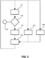
- step 101 the infrared laser system illuminates the interior of the vehicle and the camera system acquires an image of the interior of the vehicle.
- step 102 the control unit determines whether persons are located within the vehicle. In particular, the control unit determines in front of which infrared lasers a person is present. If persons are not present in front of any laser, a heating is not necessary and the heating method ends in step 107.
- step 103 the control unit detects predefined regions on the persons from the acquired image. In particular, the control unit detects most heat sensitive body parts like the face or the hands. The predefined regions can also be bare skin regions, which can be detected in the acquired image.
- the persons within the vehicle can input desired temperatures via the input unit and in step 105 the temperature sensors measure the temperatures within the cabin of the vehicle.
- the control unit controls the infrared laser system such that only lasers are activated, in front of which really a part of a person is present.
- the control unit controls the infrared laser light emitted by the infrared laser system by using control rules defining characteristics of the infrared laser light depending on the input desired temperature, the measured temperature within the cabin and the locations of the detected predefined regions like the locations of the face and the hands of the person.
- Steps 101 to 106 can be performed in a loop such that the control of the infrared laser system can be updated, if a new image is acquired by the camera system, if the desired temperature has been modified via the input unit or if the temperature within the cabin measured by the temperature sensors has been changed.
- the described heating method is only an exemplary embodiment of a heating method for heating a living being within a vehicle.
- the heating method can comprise other steps describing the heating of a living being within the vehicle by using infrared laser light of an infrared laser system.
- the infrared laser system can be controlled depending on an attention signal of a driver assist system
- the acquired image can be used for generating a temperature value, which may be related to an increase of blood supply caused by the infrared radiation
- the infrared laser system can be controlled based on the temperature value
- the heating method can be stopped after a corresponding input into the input unit by a user, et cetera.
- thermal comfort depends on four factors: a) the temperature of air around the person, b) the air velocity, c) the radiation temperature of the surrounding and d) the clothing.
- Thermal comfort in modern cars is ensured by automatic climate systems. These systems adjust the air temperature and the air velocity inside the compartment of the car. Since the car body itself is usually around five degrees colder due to strong convective cooling induced by the driving velocity, the air temperature inside the car often needs to be significantly higher than for instance a comfortable air temperature in a house.
- Electric vehicles have, however, a very good conversion ratio of electrical to mechanical energy. And, as a side effect, heating energy is not abundantly present anymore. Hence systems to heat up the car's compartment need to be electrified as well. Unfortunately these electric heating systems are so energy demanding that the battery is drained quickly, reducing the range of car. In extreme cases the reduction is reported to be 30 percent, which is not acceptable given the limited range of these vehicles.
- the heating system described above with reference to Figs. 1 and 2 uses infrared laser light, in particular, near infrared laser light, instead of, for instance, hot air, which is often used in climate systems.
- the feeling of thermal comfort can be realized with less power, wherein the solution is highly directive, i.e. only areas are heated, which really need to be heated, and the effect is instantaneous.
- the heating system is adapted to directly heat up the persons inside the vehicle. It can be adapted to avoid heating up the air around the passengers, but to still create a comfortable climate, thereby reducing the energy requirement of the heating system to an acceptable level given the limited battery capacity on board.
- the heating system preferentially makes use of arrays of lasers. These lasers emit infrared light, which can be conveniently used to heat up the skin of a passenger. In this way heat losses of the passenger can directly be compensated, thus making the person feel comfortable although the compartment's temperature is low. Moreover, the energy can be directed to those body parts where the body's own generated heat is lost the fastest like the face, avoiding a decrease in local skin temperature. Another advantage of the heating system is that the radiative heat creates a comfortable situation instant on, which is especially important for the expected use of electric cars on short distances.
- the heating system preferentially uses near infrared radiation provided by VCSELs.
- VCSELs offer a low cost and efficient source of near infrared laser radiation. Collimated output allows directionality and the small form factor enables integration in the car interior.
- the heating system preferentially provides a distributed VCSEL solution minimizing safety concerns and allowing an additional use of waste heat rather than requiring specific cooling.
- the air temperature can be kept low without losing thermal comfort. For instance, at 300 W per person infrared heat, the air temperature may be 10 degrees lower than currently needed for feeling comfortable.
- the heating system is preferentially a personalized heating system, where the driver as well as the passenger can personally decide what level of heating they want and experience as comfortable.
- different lasers can be directed, which can be controlled independently from each other by the control unit such that each person can be heated as desired.
- the near infrared light of the lasers has a relatively good penetration depth in skin. This has the advantage that the skin is heated in a larger layer, increasing the thermal comfort feeling and avoiding too high skin temperatures.
- VCSEL arrays are preferentially distributed over a large area.
- First benefit is that no active cooling is needed as in a more concentrated laser system.
- Second advantage is that laser radiation coming not from a single opening but from many angles easily fulfils laser safety considerations.
- Preferred packages are long and flexible lines of many lasers as, for instance, also used for light emitting diodes.
- Another preferred mounting position is close to the driver's feet. As these are normally at a well defined position it is easy to direct just a small amount of laser radiation to them. In addition the "frozen" position of the feet makes them especially sensitive to thermal discomfort increasing the value of the laser solution.
- the heating system is very compact and can easily be integrated in various places, it is also very well suited in the aftermarket for instantaneous heating as provided by a pre-heating of cars.
- the laser light is invisible to the human eye. Hence, the laser light is merely perceived as heat and does not disturb vision of the driver and passengers.
- the heating system described above with reference to Figs. 1 and 2 provides an advantageous combination with a camera system detecting the position of the passengers, which is an option for future cars also for improved safety.
- Near infrared light can be detected by standard CCD and CMOS cameras.
- the near infrared light of the lasers can be made visible and switched on or off in case a person is sitting in front of the arrays.
- most heat sensitive body parts can be recognized such as face, bare skin or hands.
- the light pattern of the lasers can be adjusted such that only these parts are heated. Since the heating system is preferentially instantaneous and lasers offer the unique possibility to change its light and thus heating pattern, the heating system is preferentially used to attract the driver's attention, in particular, depending on a dangerous situation detected by a driver assist system.
- the heating system comprises a camera system and a driver assist system
- the heating system may not comprise the camera system or the driver assist system.
- the heating system may be adapted to cooperate with a separate camera system and/or a separate driver assist system, wherein the separate camera system is adapted to acquire an image of the living being and to send the acquired image to the heating system for allowing the control unit of the heating system to control the infrared laser system of the heating system depending on the acquired image and wherein the driver assist system is adapted to detect a dangerous situation, to generate an attention signal, if a dangerous situation has been detected, and to send the attention signal to the heating system, in order to allow the control unit of the heating system to control the infrared laser system of the heating system depending on the attention signal.
- the image providing unit of the heating system can be a receiving unit for receiving the image from the camera system and for providing the received image to the control unit and the attention signal providing unit can be a receiving unit for receiving the attention signal from the driver assist system and for providing the received attention signal to the control unit of the heating system.
- the control unit can be adapted to determine a spatially-dependent temperature value, wherein for different regions of the person visible in the image acquired by the camera system different temperature values can be determined.
- the control unit can be adapted to locally control the different lasers of the infrared laser system depending on - inter alia - the spatially-dependent temperature value.
- the first group 5 of infrared lasers is shown only above the windshield 9, in other embodiments the first group 5 of infrared lasers can also be arranged at another location within the vehicle. Moreover, also additional groups of infrared lasers can be arranged within the vehicle. For instance, lines of infrared lasers can be arranged along the upper border, the lower border and/or the lateral borders of the windshield. Also the second group 6 of infrared lasers can be arranged at another location.
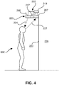
- Fig. 4 shows schematically and exemplarily a further embodiment of a heating system for heating a living being.
- the heating system 222 is arranged above a display window 223 at or within an overhang 225.
- the heating system can also be arranged at another location.
- the heating system 222 is adapted to heat a person 202 standing in front of the window display 223.
- objects are located (not shown in Fig. 4 ) which are displayed.
- the heating system 222 comprises an infrared laser system 205 being controlled by a control unit 213.
- Infrared laser light 224 emitted by the infrared laser system 205 is reflected by the person 202, wherein the reflected light 227 is detected by a camera system 207. Moreover, the ambient temperature is measured by a temperature sensor 217.
- the control unit 213 receives the ambient temperature from the temperature sensor 217 and the image from the camera system 207, in order to allow the control unit 213 to control the infrared laser system 205 depending on the ambient temperature and the acquired image.
- the control of the infrared laser system 205 depending on the ambient temperature and the acquired image can be similar to the control of the heating system within the vehicle described above with reference to Figs. 1 to 3 .
- the control unit 213 can be adapted to detect predefined regions on the person like the face or other bare skin regions from the acquired image and to control the infrared laser system 205 to provide the infrared laser light to the detected predefined regions.
- the control unit 213 can be adapted to determine a temperature value being indicative of a temperature of the person 202 from the acquired image and to control the infrared laser system 205 depending on the determined temperature value.
- the heating system can be integrated in or around the display window.
- the infrared laser system can be switched on, by which heat is instantaneously sent towards the person in front of the window.
- the directionality of the laser beams can be adjusted by, for example, a lens system, a scanning mirror system, or lasers spread around the window, and directed to heat up the body parts that are typically cold, for example, the face, the hands or any other uncovered body parts. In this way a thermal comfortable situation can be created instantaneously and flexibly. Thermal comfort is expected to be especially increased, since near-infrared radiation penetrates the skin. In this way too high skin temperatures are avoided, while heat loss is still compensated for.
- the heating system is adapted to increase the laser power to a higher level than required for a neutral, i.e. neither cold nor warm, thermal environment.
- the infrared laser system can also be combined with light emitting diodes for providing further directed illumination.
- the thermal condition of being exposed to the sun on a sunny day can be mimicked. Direct sunlight with its directed radiation heat is by humans sensed as very pleasing.
- radiation with a power within a range of 10 to 20 W may be directed to the face of a person.
- the heating system can also be adapted to be used in another environment.
- the heating system can be integrated into a bus shelter. It is obviously not economical to provide a thermal neutral environment in a bus shelter by, for example, hot air.
- the bus shelter is very irregularly occupied in time and by design has an open structure for quick shelter and for people to feel safe.
- the laser heating system can be adapted to provide the heat instantaneous, avoiding heat up times of conventional heating methods, and to aim its heat directly and optionally only to the cold bodies.
- the heating system can also be adapted to be used for, for instance, heating for outdoor sport bench, heating in outdoor areas assigned to smokers, personalized heating in an open fridge or freezer sections of a supermarket, heating person in ski lifts, heating in entrance regions of, for example, big stores et cetera.
- These situations are similar in that the occupation level is very dynamic, and by design an open, i.e. open to the outdoor, colder environment is required. Therefore heating by conventional means such as hot air is not economical due to the large heat losses to the environment.
- the heating system is adapted to heat the one or several persons
- the living being can also be an animal or a plant, which needs to be heated.
- the vehicle is a car, in other embodiments the vehicle can also be another apparatus for incorporating and moving living beings like a bus, a truck, a ship, a plane, et cetera.
- a single unit or device may fulfill the functions of several items recited in the claims.
- the mere fact that certain measures are recited in mutually different dependent claims does not indicate that a combination of these measures cannot be used to advantage.
- Operations like the determination whether a person is located in front of a laser array, the detection of predefined regions of the person, the determination of a temperature value based on an acquired image, et cetera performed by one or several units or devices can be performed by any other number of units or devices.
- steps 101 and 103 can be performed by a single unit or by any other number of different units.
- the operations and/or the control of the heating system in accordance with the heating method can be implemented as program code means of a computer program and/or as dedicated hardware.
- a computer program may be stored/distributed on a suitable medium, such as an optical storage medium or a solid-state medium, supplied together with or as part of other hardware, but may also be distributed in other forms, such as via the Internet or other wired or wireless telecommunication systems.
- a suitable medium such as an optical storage medium or a solid-state medium, supplied together with or as part of other hardware, but may also be distributed in other forms, such as via the Internet or other wired or wireless telecommunication systems.
Landscapes
- Physics & Mathematics (AREA)
- Thermal Sciences (AREA)
- Engineering & Computer Science (AREA)
- Mechanical Engineering (AREA)
- Air-Conditioning For Vehicles (AREA)
- Control Of Resistance Heating (AREA)
- Electric Propulsion And Braking For Vehicles (AREA)
Applications Claiming Priority (2)
| Application Number | Priority Date | Filing Date | Title |
|---|---|---|---|
| US201261587170P | 2012-01-17 | 2012-01-17 | |
| PCT/IB2013/050415 WO2013108197A1 (en) | 2012-01-17 | 2013-01-17 | Heating system for heating a living being |
Publications (2)
| Publication Number | Publication Date |
|---|---|
| EP2804776A1 EP2804776A1 (en) | 2014-11-26 |
| EP2804776B1 true EP2804776B1 (en) | 2018-04-25 |
Family
ID=47915298
Family Applications (1)
| Application Number | Title | Priority Date | Filing Date |
|---|---|---|---|
| EP13711469.0A Active EP2804776B1 (en) | 2012-01-17 | 2013-01-17 | Heating system for heating a living being |
Country Status (8)
| Country | Link |
|---|---|
| US (2) | US9873308B2 (ru) |
| EP (1) | EP2804776B1 (ru) |
| JP (1) | JP6215841B2 (ru) |
| CN (1) | CN104053564B (ru) |
| ES (1) | ES2672235T3 (ru) |
| RU (1) | RU2624526C2 (ru) |
| TR (1) | TR201809175T4 (ru) |
| WO (1) | WO2013108197A1 (ru) |
Families Citing this family (18)
| Publication number | Priority date | Publication date | Assignee | Title |
|---|---|---|---|---|
| DE102012020870B3 (de) * | 2012-10-24 | 2014-02-13 | Audi Ag | Heizvorrichtung für den Fahrzeuginnenraum eines Fahrzeugs |
| JP6384129B2 (ja) * | 2013-08-27 | 2018-09-05 | 株式会社デンソー | 車載用輻射ヒータ制御装置 |
| US9412222B2 (en) * | 2013-09-20 | 2016-08-09 | Igt | Coordinated gaming machine attract via gaming machine cameras |
| JP6228051B2 (ja) * | 2014-03-24 | 2017-11-08 | 株式会社Subaru | 車両用暖房装置 |
| CN103963607B (zh) * | 2014-04-26 | 2017-02-22 | 柳州博纳汽车科技有限公司 | 用于轿车内的封边式红外加热装置 |
| CN106287331A (zh) * | 2015-06-08 | 2017-01-04 | 介辉 | 加热指定空间内物体的系统和方法 |
| CN106515352A (zh) * | 2015-09-15 | 2017-03-22 | 华邦电子股份有限公司 | 交通载具空调的控制系统与控制方法 |
| KR102621079B1 (ko) * | 2016-10-17 | 2024-01-05 | 엘에스오토모티브테크놀로지스 주식회사 | 비접촉식 차량 실내 램프 유니트 |
| US10616957B2 (en) * | 2017-02-23 | 2020-04-07 | Ford Global Technologies, Llc | Heat generating system for a motor vehicle |
| US10532661B2 (en) | 2017-08-21 | 2020-01-14 | Ford Global Technologies, Llc | System and method for heating electrified vehicle |
| US10532629B2 (en) * | 2017-09-06 | 2020-01-14 | Ford Global Technologies, Llc | Radiant heating system incorporating steering wheel position monitoring device |
| JP6969985B2 (ja) * | 2017-11-14 | 2021-11-24 | トヨタ自動車株式会社 | 車両用空調装置 |
| JP7036706B2 (ja) * | 2018-12-12 | 2022-03-15 | 本田技研工業株式会社 | 車両用空調制御システム、車両用空調制御方法、およびプログラム |
| CN109711307A (zh) * | 2018-12-19 | 2019-05-03 | 中科天网(广东)科技有限公司 | 一种基于人脸识别的吸烟取证方法 |
| WO2020146596A1 (en) * | 2019-01-10 | 2020-07-16 | The Regents Of The University Of Michigan | Detecting presence and estimating thermal comfort of one or more human occupants in a built space in real-time using one or more thermographic cameras and one or more rgb-d sensors |
| DE102019211821A1 (de) * | 2019-08-07 | 2021-02-11 | Audi Ag | Heizvorrichtung |
| CN110351473A (zh) * | 2019-08-13 | 2019-10-18 | 宁波为森智能传感技术有限公司 | 疲劳驾驶监控装置 |
| KR20210080993A (ko) * | 2019-12-23 | 2021-07-01 | 엘지전자 주식회사 | 전자 장치 및 그의 동작 방법 |
Family Cites Families (56)
| Publication number | Priority date | Publication date | Assignee | Title |
|---|---|---|---|---|
| US6442465B2 (en) * | 1992-05-05 | 2002-08-27 | Automotive Technologies International, Inc. | Vehicular component control systems and methods |
| US6772057B2 (en) * | 1995-06-07 | 2004-08-03 | Automotive Technologies International, Inc. | Vehicular monitoring systems using image processing |
| US5164949A (en) * | 1991-09-09 | 1992-11-17 | Motorola, Inc. | Vertical cavity surface emitting laser with lateral injection |
| US7983817B2 (en) * | 1995-06-07 | 2011-07-19 | Automotive Technologies Internatinoal, Inc. | Method and arrangement for obtaining information about vehicle occupants |
| US20080142713A1 (en) | 1992-05-05 | 2008-06-19 | Automotive Technologies International, Inc. | Vehicular Occupant Sensing Using Infrared |
| US7738678B2 (en) * | 1995-06-07 | 2010-06-15 | Automotive Technologies International, Inc. | Light modulation techniques for imaging objects in or around a vehicle |
| US7570785B2 (en) * | 1995-06-07 | 2009-08-04 | Automotive Technologies International, Inc. | Face monitoring system and method for vehicular occupants |
| US5812571A (en) * | 1996-10-25 | 1998-09-22 | W. L. Gore & Associates, Inc. | High-power vertical cavity surface emitting laser cluster |
| JPH10160580A (ja) * | 1996-12-04 | 1998-06-19 | Zexel Corp | 熱画像の判定方法と空気調和装置の制御方法 |
| SE0002690L (sv) * | 2000-07-19 | 2002-01-20 | Kongsberg Automotive Ab | Anordning och förfarande för temperaturreglering och ventilering av ett säte |
| DE10038235A1 (de) * | 2000-08-04 | 2002-02-21 | Osram Opto Semiconductors Gmbh | Oberflächenemittierender Laser mit seitlicher Strominjektion |
| US7797966B2 (en) * | 2000-12-29 | 2010-09-21 | Single Crystal Technologies, Inc. | Hot substrate deposition of fused silica |
| US6679830B2 (en) * | 2001-02-06 | 2004-01-20 | Hill-Rom Services, Inc. | Infant incubator with non-contact sensing and monitoring |
| US7344894B2 (en) | 2001-10-16 | 2008-03-18 | Agilent Technologies, Inc. | Thermal regulation of fluidic samples within a diagnostic cartridge |
| US10683494B2 (en) * | 2001-11-01 | 2020-06-16 | Pthera LLC | Enhanced stem cell therapy and stem cell production through the administration of low level light energy |
| CN1378823A (zh) * | 2002-05-21 | 2002-11-13 | 宋世鹏 | 一种全身热疗装置 |
| US20080065291A1 (en) * | 2002-11-04 | 2008-03-13 | Automotive Technologies International, Inc. | Gesture-Based Control of Vehicular Components |
| JP2004290499A (ja) | 2003-03-27 | 2004-10-21 | Denso Corp | 車両用覚醒装置 |
| DE102004022986A1 (de) * | 2004-05-10 | 2005-10-20 | Kastriot Merlaku | Elektronisches Heiz-System für Fahrzeuge |
| US20060022213A1 (en) * | 2004-08-02 | 2006-02-02 | Posamentier Joshua D | TO-can heater on flex circuit |
| US7376451B2 (en) * | 2004-10-27 | 2008-05-20 | General Electric Company | Measurement and treatment system and method |
| US20060092401A1 (en) * | 2004-10-28 | 2006-05-04 | Troxell John R | Actively-illuminating optical sensing system for an automobile |
| US10687391B2 (en) * | 2004-12-03 | 2020-06-16 | Pressco Ip Llc | Method and system for digital narrowband, wavelength specific cooking, curing, food preparation, and processing |
| US10857722B2 (en) * | 2004-12-03 | 2020-12-08 | Pressco Ip Llc | Method and system for laser-based, wavelength specific infrared irradiation treatment |
| US7425296B2 (en) | 2004-12-03 | 2008-09-16 | Pressco Technology Inc. | Method and system for wavelength specific thermal irradiation and treatment |
| US20080046044A1 (en) * | 2006-06-15 | 2008-02-21 | Jahnigen Timothy P | Method and Apparatus to Provide Infrared Heating for an Animal |
| JP5662022B2 (ja) * | 2006-12-19 | 2015-01-28 | コーニンクレッカ フィリップス エヌ ヴェ | 製造ラインでオブジェクトを加熱するシステム及び方法 |
| DE102007015841A1 (de) * | 2006-12-22 | 2008-06-26 | W.E.T. Automotive Systems Ag | Vorrichtung mit mindestens einem Strahlungsleiter |
| JP4318054B2 (ja) * | 2007-01-11 | 2009-08-19 | 株式会社デンソー | 自動車用局所冷房システム |
| DE102007015814A1 (de) | 2007-03-30 | 2008-10-09 | Solmic Gmbh | Verfahren und Vorrichtung zur Reinigung von Schmelzen, insbesondere von Siliziumschmelzen |
| US20100324398A1 (en) * | 2007-05-11 | 2010-12-23 | Jung Tzyy-Ping | Non-invasive characterization of a physiological parameter |
| US20090287069A1 (en) * | 2007-11-25 | 2009-11-19 | Ic Therapeutics | Methods and apparatus for repeated ischemic conditioning treatment of hypertension and other medical conditions |
| WO2008155893A1 (ja) * | 2007-06-15 | 2008-12-24 | Panasonic Corporation | 車両用暖房装置 |
| US20100258645A1 (en) | 2007-12-13 | 2010-10-14 | Panasonic Corporation | Vehicle heating system |
| US8160718B2 (en) * | 2008-01-04 | 2012-04-17 | Draeger Medical Systems, Inc. | Method and apparatus for performing warming therapy utilizing matrix heating |
| US8676044B2 (en) * | 2008-03-19 | 2014-03-18 | Sunlighten, Inc. | Dynamic sauna |
| CN201264548Y (zh) * | 2008-08-11 | 2009-07-01 | 黄耀生 | 远红外加热保温汽车颈枕 |
| JP5309844B2 (ja) * | 2008-09-29 | 2013-10-09 | 株式会社デンソー | 車両用空調装置 |
| DE102008059553B4 (de) * | 2008-11-28 | 2012-10-25 | Behr-Hella Thermocontrol Gmbh | Verfahren zur Regelung der Innenraumtemperatur in einem Fahrzeug |
| US8859938B2 (en) | 2009-01-26 | 2014-10-14 | Nissan North America, Inc. | Vehicle cabin heating system |
| US7949024B2 (en) * | 2009-02-17 | 2011-05-24 | Trilumina Corporation | Multibeam arrays of optoelectronic devices for high frequency operation |
| US10244181B2 (en) * | 2009-02-17 | 2019-03-26 | Trilumina Corp. | Compact multi-zone infrared laser illuminator |
| US8995493B2 (en) * | 2009-02-17 | 2015-03-31 | Trilumina Corp. | Microlenses for multibeam arrays of optoelectronic devices for high frequency operation |
| BRPI1010249A2 (pt) * | 2009-03-05 | 2016-03-22 | Pressco Tech Inc | injeção de calor digital por via de dispositivo semicondutores de emissão superficial |
| US9375171B2 (en) * | 2009-04-22 | 2016-06-28 | Rodrigo E. Teixeira | Probabilistic biomedical parameter estimation apparatus and method of operation therefor |
| US9517681B2 (en) * | 2009-08-21 | 2016-12-13 | Martin A. Alpert | Apparatus and method for radiant heating and cooling for vehicles |
| CA2774523A1 (en) * | 2009-09-18 | 2011-03-24 | Pressco Technology, Inc. | A narrowband de-icing and ice release system and method |
| US8608786B2 (en) * | 2009-09-18 | 2013-12-17 | Dror Irge | Apparatus for delivering multiple forms of electromagnetic radiation and method for its use |
| CN102640380B (zh) | 2009-09-28 | 2015-06-17 | 电力消防栓有限责任公司 | 用于对电动车辆充电的方法和系统 |
| FR2954690A1 (fr) * | 2009-12-29 | 2011-07-01 | Ekkyo | Dispositif de traitement dermatologique par faisceau lumineux |
| US20120030873A1 (en) * | 2010-08-04 | 2012-02-09 | Anodyne Therapy, L.L.C. | Integrated system, method and apparatus for treating back pain during rest |
| DE102012102101A1 (de) * | 2011-03-17 | 2013-03-21 | General Electric Company | Säuglingswärmegerät und Verfahren |
| DE102011089195A1 (de) * | 2011-06-30 | 2013-01-03 | Johnson Controls Gmbh | Vorrichtung und Verfahren zur berührungslosen Erfassung von Gegenständen und/oder Personen und von diesen ausgeführten Gesten und/oder Bedienvorgängen |
| FR2982790B1 (fr) * | 2011-11-21 | 2014-03-14 | Sidel Participations | Unite de traitement thermique d'ebauches de recipients a double paroi rayonnante en quinconce |
| US20140301724A1 (en) * | 2013-04-06 | 2014-10-09 | David Silliman Graham | Electronic Heating of People and Animals |
| US20150028114A1 (en) * | 2013-07-29 | 2015-01-29 | Howard Rosen | Apparatus and method for controlling a heating ventilation and / or air conditioning system utilizing an infrared sensing or imaging device for determining radiated temperature of one or more objects or occupants in the conditioned space |
-
2013
- 2013-01-17 TR TR2018/09175T patent/TR201809175T4/tr unknown
- 2013-01-17 RU RU2014133748A patent/RU2624526C2/ru not_active IP Right Cessation
- 2013-01-17 JP JP2014551725A patent/JP6215841B2/ja active Active
- 2013-01-17 US US14/369,222 patent/US9873308B2/en active Active
- 2013-01-17 ES ES13711469.0T patent/ES2672235T3/es active Active
- 2013-01-17 CN CN201380005813.3A patent/CN104053564B/zh active Active
- 2013-01-17 WO PCT/IB2013/050415 patent/WO2013108197A1/en active Application Filing
- 2013-01-17 EP EP13711469.0A patent/EP2804776B1/en active Active
-
2018
- 2018-01-03 US US15/860,744 patent/US10757758B2/en active Active
Non-Patent Citations (1)
| Title |
|---|
| None * |
Also Published As
| Publication number | Publication date |
|---|---|
| US9873308B2 (en) | 2018-01-23 |
| JP6215841B2 (ja) | 2017-10-18 |
| ES2672235T3 (es) | 2018-06-13 |
| US10757758B2 (en) | 2020-08-25 |
| CN104053564B (zh) | 2017-12-19 |
| EP2804776A1 (en) | 2014-11-26 |
| CN104053564A (zh) | 2014-09-17 |
| JP2015510660A (ja) | 2015-04-09 |
| RU2014133748A (ru) | 2016-03-10 |
| TR201809175T4 (tr) | 2018-07-23 |
| US20180126821A1 (en) | 2018-05-10 |
| RU2624526C2 (ru) | 2017-07-04 |
| WO2013108197A1 (en) | 2013-07-25 |
| US20140346160A1 (en) | 2014-11-27 |
Similar Documents
| Publication | Publication Date | Title |
|---|---|---|
| US10757758B2 (en) | Heating system for heating a living being | |
| CN108981932B (zh) | 热图像传感器以及空气调节机 | |
| US10926773B2 (en) | Systems and methods for mitigating motion sickness in a vehicle | |
| US20170124987A1 (en) | Vehicle and method for controlling the vehicle | |
| JP5311628B2 (ja) | 車両照明システム | |
| US20150028119A1 (en) | Method of Heating the Interior of a Vehicle | |
| CN106168508A (zh) | 受光传感器、使用它的空调机、电子烹饪设备和运输设备 | |
| US20200096636A1 (en) | Distance measurement system | |
| US20180357520A1 (en) | Protective system for infrared light source | |
| EP3587186B1 (en) | Vehicle interior lighting system | |
| EP1731365B1 (en) | Illumination apparatus for an optical occupant monitoring system in a vehicle | |
| US11697381B2 (en) | Device and method for operating an object detection system for the passenger compartment of a motor vehicle, and a motor vehicle | |
| US20200231111A1 (en) | Vehicle footwell reflector | |
| US10631369B2 (en) | Infra-red device for focused heating | |
| US20220185170A1 (en) | Exterior lighting system for motor vehicle | |
| JP7063106B2 (ja) | 日射強度算出装置および空調システム | |
| US20220172489A1 (en) | Systems and methods for object detection in the interior of a motor vehicle | |
| JP2002005747A (ja) | 温度分布データの処理方法 | |
| US20220258864A1 (en) | Occupant tracking lighting system | |
| CN117048482A (zh) | 用于机动车辆的外部照明系统 | |
| JP2022155792A (ja) | 曇り止めシステム | |
| JP2021077139A (ja) | 運転者状態推定装置 |
Legal Events
| Date | Code | Title | Description |
|---|---|---|---|
| PUAI | Public reference made under article 153(3) epc to a published international application that has entered the european phase |
Free format text: ORIGINAL CODE: 0009012 |
|
| 17P | Request for examination filed |
Effective date: 20140818 |
|
| AK | Designated contracting states |
Kind code of ref document: A1 Designated state(s): AL AT BE BG CH CY CZ DE DK EE ES FI FR GB GR HR HU IE IS IT LI LT LU LV MC MK MT NL NO PL PT RO RS SE SI SK SM TR |
|
| DAX | Request for extension of the european patent (deleted) | ||
| STAA | Information on the status of an ep patent application or granted ep patent |
Free format text: STATUS: EXAMINATION IS IN PROGRESS |
|
| 17Q | First examination report despatched |
Effective date: 20170807 |
|
| GRAP | Despatch of communication of intention to grant a patent |
Free format text: ORIGINAL CODE: EPIDOSNIGR1 |
|
| STAA | Information on the status of an ep patent application or granted ep patent |
Free format text: STATUS: GRANT OF PATENT IS INTENDED |
|
| INTG | Intention to grant announced |
Effective date: 20171116 |
|
| GRAA | (expected) grant |
Free format text: ORIGINAL CODE: 0009210 |
|
| GRAS | Grant fee paid |
Free format text: ORIGINAL CODE: EPIDOSNIGR3 |
|
| STAA | Information on the status of an ep patent application or granted ep patent |
Free format text: STATUS: THE PATENT HAS BEEN GRANTED |
|
| AK | Designated contracting states |
Kind code of ref document: B1 Designated state(s): AL AT BE BG CH CY CZ DE DK EE ES FI FR GB GR HR HU IE IS IT LI LT LU LV MC MK MT NL NO PL PT RO RS SE SI SK SM TR |
|
| REG | Reference to a national code |
Ref country code: GB Ref legal event code: FG4D |
|
| REG | Reference to a national code |
Ref country code: CH Ref legal event code: EP |
|
| REG | Reference to a national code |
Ref country code: AT Ref legal event code: REF Ref document number: 992476 Country of ref document: AT Kind code of ref document: T Effective date: 20180515 |
|
| REG | Reference to a national code |
Ref country code: IE Ref legal event code: FG4D |
|
| REG | Reference to a national code |
Ref country code: DE Ref legal event code: R096 Ref document number: 602013036420 Country of ref document: DE |
|
| REG | Reference to a national code |
Ref country code: ES Ref legal event code: FG2A Ref document number: 2672235 Country of ref document: ES Kind code of ref document: T3 Effective date: 20180613 |
|
| REG | Reference to a national code |
Ref country code: NL Ref legal event code: MP Effective date: 20180425 |
|
| REG | Reference to a national code |
Ref country code: LT Ref legal event code: MG4D |
|
| PG25 | Lapsed in a contracting state [announced via postgrant information from national office to epo] |
Ref country code: NL Free format text: LAPSE BECAUSE OF FAILURE TO SUBMIT A TRANSLATION OF THE DESCRIPTION OR TO PAY THE FEE WITHIN THE PRESCRIBED TIME-LIMIT Effective date: 20180425 |
|
| PG25 | Lapsed in a contracting state [announced via postgrant information from national office to epo] |
Ref country code: BG Free format text: LAPSE BECAUSE OF FAILURE TO SUBMIT A TRANSLATION OF THE DESCRIPTION OR TO PAY THE FEE WITHIN THE PRESCRIBED TIME-LIMIT Effective date: 20180725 Ref country code: NO Free format text: LAPSE BECAUSE OF FAILURE TO SUBMIT A TRANSLATION OF THE DESCRIPTION OR TO PAY THE FEE WITHIN THE PRESCRIBED TIME-LIMIT Effective date: 20180725 Ref country code: FI Free format text: LAPSE BECAUSE OF FAILURE TO SUBMIT A TRANSLATION OF THE DESCRIPTION OR TO PAY THE FEE WITHIN THE PRESCRIBED TIME-LIMIT Effective date: 20180425 Ref country code: SE Free format text: LAPSE BECAUSE OF FAILURE TO SUBMIT A TRANSLATION OF THE DESCRIPTION OR TO PAY THE FEE WITHIN THE PRESCRIBED TIME-LIMIT Effective date: 20180425 Ref country code: PL Free format text: LAPSE BECAUSE OF FAILURE TO SUBMIT A TRANSLATION OF THE DESCRIPTION OR TO PAY THE FEE WITHIN THE PRESCRIBED TIME-LIMIT Effective date: 20180425 Ref country code: LT Free format text: LAPSE BECAUSE OF FAILURE TO SUBMIT A TRANSLATION OF THE DESCRIPTION OR TO PAY THE FEE WITHIN THE PRESCRIBED TIME-LIMIT Effective date: 20180425 |
|
| PG25 | Lapsed in a contracting state [announced via postgrant information from national office to epo] |
Ref country code: LV Free format text: LAPSE BECAUSE OF FAILURE TO SUBMIT A TRANSLATION OF THE DESCRIPTION OR TO PAY THE FEE WITHIN THE PRESCRIBED TIME-LIMIT Effective date: 20180425 Ref country code: HR Free format text: LAPSE BECAUSE OF FAILURE TO SUBMIT A TRANSLATION OF THE DESCRIPTION OR TO PAY THE FEE WITHIN THE PRESCRIBED TIME-LIMIT Effective date: 20180425 Ref country code: GR Free format text: LAPSE BECAUSE OF FAILURE TO SUBMIT A TRANSLATION OF THE DESCRIPTION OR TO PAY THE FEE WITHIN THE PRESCRIBED TIME-LIMIT Effective date: 20180726 Ref country code: RS Free format text: LAPSE BECAUSE OF FAILURE TO SUBMIT A TRANSLATION OF THE DESCRIPTION OR TO PAY THE FEE WITHIN THE PRESCRIBED TIME-LIMIT Effective date: 20180425 |
|
| REG | Reference to a national code |
Ref country code: AT Ref legal event code: MK05 Ref document number: 992476 Country of ref document: AT Kind code of ref document: T Effective date: 20180425 |
|
| PG25 | Lapsed in a contracting state [announced via postgrant information from national office to epo] |
Ref country code: PT Free format text: LAPSE BECAUSE OF FAILURE TO SUBMIT A TRANSLATION OF THE DESCRIPTION OR TO PAY THE FEE WITHIN THE PRESCRIBED TIME-LIMIT Effective date: 20180827 |
|
| REG | Reference to a national code |
Ref country code: DE Ref legal event code: R097 Ref document number: 602013036420 Country of ref document: DE |
|
| PG25 | Lapsed in a contracting state [announced via postgrant information from national office to epo] |
Ref country code: EE Free format text: LAPSE BECAUSE OF FAILURE TO SUBMIT A TRANSLATION OF THE DESCRIPTION OR TO PAY THE FEE WITHIN THE PRESCRIBED TIME-LIMIT Effective date: 20180425 Ref country code: DK Free format text: LAPSE BECAUSE OF FAILURE TO SUBMIT A TRANSLATION OF THE DESCRIPTION OR TO PAY THE FEE WITHIN THE PRESCRIBED TIME-LIMIT Effective date: 20180425 Ref country code: AT Free format text: LAPSE BECAUSE OF FAILURE TO SUBMIT A TRANSLATION OF THE DESCRIPTION OR TO PAY THE FEE WITHIN THE PRESCRIBED TIME-LIMIT Effective date: 20180425 Ref country code: CZ Free format text: LAPSE BECAUSE OF FAILURE TO SUBMIT A TRANSLATION OF THE DESCRIPTION OR TO PAY THE FEE WITHIN THE PRESCRIBED TIME-LIMIT Effective date: 20180425 Ref country code: RO Free format text: LAPSE BECAUSE OF FAILURE TO SUBMIT A TRANSLATION OF THE DESCRIPTION OR TO PAY THE FEE WITHIN THE PRESCRIBED TIME-LIMIT Effective date: 20180425 Ref country code: SK Free format text: LAPSE BECAUSE OF FAILURE TO SUBMIT A TRANSLATION OF THE DESCRIPTION OR TO PAY THE FEE WITHIN THE PRESCRIBED TIME-LIMIT Effective date: 20180425 |
|
| REG | Reference to a national code |
Ref country code: DE Ref legal event code: R081 Ref document number: 602013036420 Country of ref document: DE Owner name: PHILIPS GMBH, DE Free format text: FORMER OWNER: PHILIPS DEUTSCHLAND GMBH, 20099 HAMBURG, DE Ref country code: DE Ref legal event code: R081 Ref document number: 602013036420 Country of ref document: DE Owner name: TRUMPF PHOTONIC COMPONENTS GMBH, DE Free format text: FORMER OWNER: PHILIPS DEUTSCHLAND GMBH, 20099 HAMBURG, DE |
|
| PG25 | Lapsed in a contracting state [announced via postgrant information from national office to epo] |
Ref country code: SM Free format text: LAPSE BECAUSE OF FAILURE TO SUBMIT A TRANSLATION OF THE DESCRIPTION OR TO PAY THE FEE WITHIN THE PRESCRIBED TIME-LIMIT Effective date: 20180425 |
|
| PLBE | No opposition filed within time limit |
Free format text: ORIGINAL CODE: 0009261 |
|
| STAA | Information on the status of an ep patent application or granted ep patent |
Free format text: STATUS: NO OPPOSITION FILED WITHIN TIME LIMIT |
|
| 26N | No opposition filed |
Effective date: 20190128 |
|
| PG25 | Lapsed in a contracting state [announced via postgrant information from national office to epo] |
Ref country code: SI Free format text: LAPSE BECAUSE OF FAILURE TO SUBMIT A TRANSLATION OF THE DESCRIPTION OR TO PAY THE FEE WITHIN THE PRESCRIBED TIME-LIMIT Effective date: 20180425 |
|
| PG25 | Lapsed in a contracting state [announced via postgrant information from national office to epo] |
Ref country code: MC Free format text: LAPSE BECAUSE OF FAILURE TO SUBMIT A TRANSLATION OF THE DESCRIPTION OR TO PAY THE FEE WITHIN THE PRESCRIBED TIME-LIMIT Effective date: 20180425 |
|
| REG | Reference to a national code |
Ref country code: CH Ref legal event code: PL |
|
| PG25 | Lapsed in a contracting state [announced via postgrant information from national office to epo] |
Ref country code: LU Free format text: LAPSE BECAUSE OF NON-PAYMENT OF DUE FEES Effective date: 20190117 |
|
| REG | Reference to a national code |
Ref country code: BE Ref legal event code: MM Effective date: 20190131 |
|
| REG | Reference to a national code |
Ref country code: IE Ref legal event code: MM4A |
|
| PG25 | Lapsed in a contracting state [announced via postgrant information from national office to epo] |
Ref country code: AL Free format text: LAPSE BECAUSE OF FAILURE TO SUBMIT A TRANSLATION OF THE DESCRIPTION OR TO PAY THE FEE WITHIN THE PRESCRIBED TIME-LIMIT Effective date: 20180425 Ref country code: BE Free format text: LAPSE BECAUSE OF NON-PAYMENT OF DUE FEES Effective date: 20190131 |
|
| PG25 | Lapsed in a contracting state [announced via postgrant information from national office to epo] |
Ref country code: LI Free format text: LAPSE BECAUSE OF NON-PAYMENT OF DUE FEES Effective date: 20190131 Ref country code: CH Free format text: LAPSE BECAUSE OF NON-PAYMENT OF DUE FEES Effective date: 20190131 |
|
| PG25 | Lapsed in a contracting state [announced via postgrant information from national office to epo] |
Ref country code: IE Free format text: LAPSE BECAUSE OF NON-PAYMENT OF DUE FEES Effective date: 20190117 |
|
| PGFP | Annual fee paid to national office [announced via postgrant information from national office to epo] |
Ref country code: IT Payment date: 20200131 Year of fee payment: 8 Ref country code: ES Payment date: 20200221 Year of fee payment: 8 |
|
| PG25 | Lapsed in a contracting state [announced via postgrant information from national office to epo] |
Ref country code: MT Free format text: LAPSE BECAUSE OF NON-PAYMENT OF DUE FEES Effective date: 20190117 |
|
| PGFP | Annual fee paid to national office [announced via postgrant information from national office to epo] |
Ref country code: TR Payment date: 20200116 Year of fee payment: 8 |
|
| REG | Reference to a national code |
Ref country code: GB Ref legal event code: 732E Free format text: REGISTERED BETWEEN 20200730 AND 20200805 |
|
| REG | Reference to a national code |
Ref country code: DE Ref legal event code: R081 Ref document number: 602013036420 Country of ref document: DE Owner name: TRUMPF PHOTONIC COMPONENTS GMBH, DE Free format text: FORMER OWNER: PHILIPS GMBH, 22335 HAMBURG, DE |
|
| PG25 | Lapsed in a contracting state [announced via postgrant information from national office to epo] |
Ref country code: CY Free format text: LAPSE BECAUSE OF FAILURE TO SUBMIT A TRANSLATION OF THE DESCRIPTION OR TO PAY THE FEE WITHIN THE PRESCRIBED TIME-LIMIT Effective date: 20180425 |
|
| PG25 | Lapsed in a contracting state [announced via postgrant information from national office to epo] |
Ref country code: IS Free format text: LAPSE BECAUSE OF FAILURE TO SUBMIT A TRANSLATION OF THE DESCRIPTION OR TO PAY THE FEE WITHIN THE PRESCRIBED TIME-LIMIT Effective date: 20180825 |
|
| PG25 | Lapsed in a contracting state [announced via postgrant information from national office to epo] |
Ref country code: HU Free format text: LAPSE BECAUSE OF FAILURE TO SUBMIT A TRANSLATION OF THE DESCRIPTION OR TO PAY THE FEE WITHIN THE PRESCRIBED TIME-LIMIT; INVALID AB INITIO Effective date: 20130117 |
|
| PG25 | Lapsed in a contracting state [announced via postgrant information from national office to epo] |
Ref country code: IT Free format text: LAPSE BECAUSE OF NON-PAYMENT OF DUE FEES Effective date: 20210117 |
|
| REG | Reference to a national code |
Ref country code: ES Ref legal event code: FD2A Effective date: 20220504 |
|
| PG25 | Lapsed in a contracting state [announced via postgrant information from national office to epo] |
Ref country code: MK Free format text: LAPSE BECAUSE OF FAILURE TO SUBMIT A TRANSLATION OF THE DESCRIPTION OR TO PAY THE FEE WITHIN THE PRESCRIBED TIME-LIMIT Effective date: 20180425 |
|
| PG25 | Lapsed in a contracting state [announced via postgrant information from national office to epo] |
Ref country code: ES Free format text: LAPSE BECAUSE OF NON-PAYMENT OF DUE FEES Effective date: 20210118 |
|
| PGFP | Annual fee paid to national office [announced via postgrant information from national office to epo] |
Ref country code: FR Payment date: 20230124 Year of fee payment: 11 |
|
| PGFP | Annual fee paid to national office [announced via postgrant information from national office to epo] |
Ref country code: DE Payment date: 20240119 Year of fee payment: 12 Ref country code: GB Payment date: 20240123 Year of fee payment: 12 |