EP2804246B1 - Brennstoffzellensystem - Google Patents
Brennstoffzellensystem Download PDFInfo
- Publication number
- EP2804246B1 EP2804246B1 EP13736353.7A EP13736353A EP2804246B1 EP 2804246 B1 EP2804246 B1 EP 2804246B1 EP 13736353 A EP13736353 A EP 13736353A EP 2804246 B1 EP2804246 B1 EP 2804246B1
- Authority
- EP
- European Patent Office
- Prior art keywords
- flow rate
- cathode
- fuel cell
- internal resistance
- cathode gas
- Prior art date
- Legal status (The legal status is an assumption and is not a legal conclusion. Google has not performed a legal analysis and makes no representation as to the accuracy of the status listed.)
- Not-in-force
Links
- 239000000446 fuel Substances 0.000 title claims description 151
- 238000001514 detection method Methods 0.000 claims description 19
- 230000007423 decrease Effects 0.000 claims description 12
- 230000003247 decreasing effect Effects 0.000 claims description 7
- 239000007789 gas Substances 0.000 description 118
- 239000003792 electrolyte Substances 0.000 description 37
- 239000012528 membrane Substances 0.000 description 36
- 239000000498 cooling water Substances 0.000 description 22
- 230000001276 controlling effect Effects 0.000 description 13
- 238000000034 method Methods 0.000 description 12
- XLYOFNOQVPJJNP-UHFFFAOYSA-N water Substances O XLYOFNOQVPJJNP-UHFFFAOYSA-N 0.000 description 8
- 230000001105 regulatory effect Effects 0.000 description 7
- 238000001816 cooling Methods 0.000 description 5
- 238000003411 electrode reaction Methods 0.000 description 4
- 239000007800 oxidant agent Substances 0.000 description 4
- 238000010248 power generation Methods 0.000 description 3
- 238000011144 upstream manufacturing Methods 0.000 description 3
- IJGRMHOSHXDMSA-UHFFFAOYSA-N Atomic nitrogen Chemical compound N#N IJGRMHOSHXDMSA-UHFFFAOYSA-N 0.000 description 2
- 238000010586 diagram Methods 0.000 description 2
- 238000002474 experimental method Methods 0.000 description 2
- 230000006870 function Effects 0.000 description 2
- 230000036571 hydration Effects 0.000 description 2
- 238000006703 hydration reaction Methods 0.000 description 2
- 239000000203 mixture Substances 0.000 description 2
- 230000001590 oxidative effect Effects 0.000 description 2
- UFHFLCQGNIYNRP-UHFFFAOYSA-N Hydrogen Chemical compound [H][H] UFHFLCQGNIYNRP-UHFFFAOYSA-N 0.000 description 1
- QVGXLLKOCUKJST-UHFFFAOYSA-N atomic oxygen Chemical compound [O] QVGXLLKOCUKJST-UHFFFAOYSA-N 0.000 description 1
- 230000002596 correlated effect Effects 0.000 description 1
- 230000000593 degrading effect Effects 0.000 description 1
- 230000000994 depressogenic effect Effects 0.000 description 1
- 230000006866 deterioration Effects 0.000 description 1
- 239000006185 dispersion Substances 0.000 description 1
- 230000000694 effects Effects 0.000 description 1
- 239000002737 fuel gas Substances 0.000 description 1
- XLYOFNOQVPJJNP-ZSJDYOACSA-N heavy water Substances [2H]O[2H] XLYOFNOQVPJJNP-ZSJDYOACSA-N 0.000 description 1
- 239000001257 hydrogen Substances 0.000 description 1
- 229910052739 hydrogen Inorganic materials 0.000 description 1
- 239000011261 inert gas Substances 0.000 description 1
- 238000010030 laminating Methods 0.000 description 1
- 238000012544 monitoring process Methods 0.000 description 1
- 229910052757 nitrogen Inorganic materials 0.000 description 1
- 239000001301 oxygen Substances 0.000 description 1
- 229910052760 oxygen Inorganic materials 0.000 description 1
- 238000011084 recovery Methods 0.000 description 1
- 239000000126 substance Substances 0.000 description 1
Images


Classifications
-
- H—ELECTRICITY
- H01—ELECTRIC ELEMENTS
- H01M—PROCESSES OR MEANS, e.g. BATTERIES, FOR THE DIRECT CONVERSION OF CHEMICAL ENERGY INTO ELECTRICAL ENERGY
- H01M8/00—Fuel cells; Manufacture thereof
- H01M8/04—Auxiliary arrangements, e.g. for control of pressure or for circulation of fluids
- H01M8/04298—Processes for controlling fuel cells or fuel cell systems
- H01M8/04694—Processes for controlling fuel cells or fuel cell systems characterised by variables to be controlled
- H01M8/04746—Pressure; Flow
- H01M8/04753—Pressure; Flow of fuel cell reactants
-
- H—ELECTRICITY
- H01—ELECTRIC ELEMENTS
- H01M—PROCESSES OR MEANS, e.g. BATTERIES, FOR THE DIRECT CONVERSION OF CHEMICAL ENERGY INTO ELECTRICAL ENERGY
- H01M8/00—Fuel cells; Manufacture thereof
- H01M8/04—Auxiliary arrangements, e.g. for control of pressure or for circulation of fluids
- H01M8/04082—Arrangements for control of reactant parameters, e.g. pressure or concentration
- H01M8/04089—Arrangements for control of reactant parameters, e.g. pressure or concentration of gaseous reactants
-
- H—ELECTRICITY
- H01—ELECTRIC ELEMENTS
- H01M—PROCESSES OR MEANS, e.g. BATTERIES, FOR THE DIRECT CONVERSION OF CHEMICAL ENERGY INTO ELECTRICAL ENERGY
- H01M8/00—Fuel cells; Manufacture thereof
- H01M8/04—Auxiliary arrangements, e.g. for control of pressure or for circulation of fluids
- H01M8/04298—Processes for controlling fuel cells or fuel cell systems
- H01M8/04313—Processes for controlling fuel cells or fuel cell systems characterised by the detection or assessment of variables; characterised by the detection or assessment of failure or abnormal function
- H01M8/0432—Temperature; Ambient temperature
- H01M8/04365—Temperature; Ambient temperature of other components of a fuel cell or fuel cell stacks
-
- H—ELECTRICITY
- H01—ELECTRIC ELEMENTS
- H01M—PROCESSES OR MEANS, e.g. BATTERIES, FOR THE DIRECT CONVERSION OF CHEMICAL ENERGY INTO ELECTRICAL ENERGY
- H01M8/00—Fuel cells; Manufacture thereof
- H01M8/04—Auxiliary arrangements, e.g. for control of pressure or for circulation of fluids
- H01M8/04298—Processes for controlling fuel cells or fuel cell systems
- H01M8/04313—Processes for controlling fuel cells or fuel cell systems characterised by the detection or assessment of variables; characterised by the detection or assessment of failure or abnormal function
- H01M8/0438—Pressure; Ambient pressure; Flow
- H01M8/04388—Pressure; Ambient pressure; Flow of anode reactants at the inlet or inside the fuel cell
-
- H—ELECTRICITY
- H01—ELECTRIC ELEMENTS
- H01M—PROCESSES OR MEANS, e.g. BATTERIES, FOR THE DIRECT CONVERSION OF CHEMICAL ENERGY INTO ELECTRICAL ENERGY
- H01M8/00—Fuel cells; Manufacture thereof
- H01M8/04—Auxiliary arrangements, e.g. for control of pressure or for circulation of fluids
- H01M8/04298—Processes for controlling fuel cells or fuel cell systems
- H01M8/04313—Processes for controlling fuel cells or fuel cell systems characterised by the detection or assessment of variables; characterised by the detection or assessment of failure or abnormal function
- H01M8/0438—Pressure; Ambient pressure; Flow
- H01M8/04395—Pressure; Ambient pressure; Flow of cathode reactants at the inlet or inside the fuel cell
-
- H—ELECTRICITY
- H01—ELECTRIC ELEMENTS
- H01M—PROCESSES OR MEANS, e.g. BATTERIES, FOR THE DIRECT CONVERSION OF CHEMICAL ENERGY INTO ELECTRICAL ENERGY
- H01M8/00—Fuel cells; Manufacture thereof
- H01M8/04—Auxiliary arrangements, e.g. for control of pressure or for circulation of fluids
- H01M8/04298—Processes for controlling fuel cells or fuel cell systems
- H01M8/04313—Processes for controlling fuel cells or fuel cell systems characterised by the detection or assessment of variables; characterised by the detection or assessment of failure or abnormal function
- H01M8/04537—Electric variables
- H01M8/04634—Other electric variables, e.g. resistance or impedance
- H01M8/04641—Other electric variables, e.g. resistance or impedance of the individual fuel cell
-
- H—ELECTRICITY
- H01—ELECTRIC ELEMENTS
- H01M—PROCESSES OR MEANS, e.g. BATTERIES, FOR THE DIRECT CONVERSION OF CHEMICAL ENERGY INTO ELECTRICAL ENERGY
- H01M8/00—Fuel cells; Manufacture thereof
- H01M8/04—Auxiliary arrangements, e.g. for control of pressure or for circulation of fluids
- H01M8/04298—Processes for controlling fuel cells or fuel cell systems
- H01M8/04313—Processes for controlling fuel cells or fuel cell systems characterised by the detection or assessment of variables; characterised by the detection or assessment of failure or abnormal function
- H01M8/04537—Electric variables
- H01M8/04634—Other electric variables, e.g. resistance or impedance
- H01M8/04649—Other electric variables, e.g. resistance or impedance of fuel cell stacks
-
- H—ELECTRICITY
- H01—ELECTRIC ELEMENTS
- H01M—PROCESSES OR MEANS, e.g. BATTERIES, FOR THE DIRECT CONVERSION OF CHEMICAL ENERGY INTO ELECTRICAL ENERGY
- H01M8/00—Fuel cells; Manufacture thereof
- H01M8/04—Auxiliary arrangements, e.g. for control of pressure or for circulation of fluids
- H01M8/04298—Processes for controlling fuel cells or fuel cell systems
- H01M8/04694—Processes for controlling fuel cells or fuel cell systems characterised by variables to be controlled
- H01M8/04858—Electric variables
- H01M8/04949—Electric variables other electric variables, e.g. resistance or impedance
- H01M8/04952—Electric variables other electric variables, e.g. resistance or impedance of fuel cell stacks
-
- H—ELECTRICITY
- H01—ELECTRIC ELEMENTS
- H01M—PROCESSES OR MEANS, e.g. BATTERIES, FOR THE DIRECT CONVERSION OF CHEMICAL ENERGY INTO ELECTRICAL ENERGY
- H01M8/00—Fuel cells; Manufacture thereof
- H01M8/10—Fuel cells with solid electrolytes
- H01M2008/1095—Fuel cells with polymeric electrolytes
-
- H—ELECTRICITY
- H01—ELECTRIC ELEMENTS
- H01M—PROCESSES OR MEANS, e.g. BATTERIES, FOR THE DIRECT CONVERSION OF CHEMICAL ENERGY INTO ELECTRICAL ENERGY
- H01M8/00—Fuel cells; Manufacture thereof
- H01M8/04—Auxiliary arrangements, e.g. for control of pressure or for circulation of fluids
- H01M8/04082—Arrangements for control of reactant parameters, e.g. pressure or concentration
- H01M8/04089—Arrangements for control of reactant parameters, e.g. pressure or concentration of gaseous reactants
- H01M8/04119—Arrangements for control of reactant parameters, e.g. pressure or concentration of gaseous reactants with simultaneous supply or evacuation of electrolyte; Humidifying or dehumidifying
- H01M8/04126—Humidifying
- H01M8/04141—Humidifying by water containing exhaust gases
-
- H—ELECTRICITY
- H01—ELECTRIC ELEMENTS
- H01M—PROCESSES OR MEANS, e.g. BATTERIES, FOR THE DIRECT CONVERSION OF CHEMICAL ENERGY INTO ELECTRICAL ENERGY
- H01M8/00—Fuel cells; Manufacture thereof
- H01M8/04—Auxiliary arrangements, e.g. for control of pressure or for circulation of fluids
- H01M8/04298—Processes for controlling fuel cells or fuel cell systems
- H01M8/04313—Processes for controlling fuel cells or fuel cell systems characterised by the detection or assessment of variables; characterised by the detection or assessment of failure or abnormal function
- H01M8/0432—Temperature; Ambient temperature
- H01M8/04358—Temperature; Ambient temperature of the coolant
-
- H—ELECTRICITY
- H01—ELECTRIC ELEMENTS
- H01M—PROCESSES OR MEANS, e.g. BATTERIES, FOR THE DIRECT CONVERSION OF CHEMICAL ENERGY INTO ELECTRICAL ENERGY
- H01M8/00—Fuel cells; Manufacture thereof
- H01M8/04—Auxiliary arrangements, e.g. for control of pressure or for circulation of fluids
- H01M8/04298—Processes for controlling fuel cells or fuel cell systems
- H01M8/04313—Processes for controlling fuel cells or fuel cell systems characterised by the detection or assessment of variables; characterised by the detection or assessment of failure or abnormal function
- H01M8/04492—Humidity; Ambient humidity; Water content
- H01M8/04507—Humidity; Ambient humidity; Water content of cathode reactants at the inlet or inside the fuel cell
-
- Y—GENERAL TAGGING OF NEW TECHNOLOGICAL DEVELOPMENTS; GENERAL TAGGING OF CROSS-SECTIONAL TECHNOLOGIES SPANNING OVER SEVERAL SECTIONS OF THE IPC; TECHNICAL SUBJECTS COVERED BY FORMER USPC CROSS-REFERENCE ART COLLECTIONS [XRACs] AND DIGESTS
- Y02—TECHNOLOGIES OR APPLICATIONS FOR MITIGATION OR ADAPTATION AGAINST CLIMATE CHANGE
- Y02E—REDUCTION OF GREENHOUSE GAS [GHG] EMISSIONS, RELATED TO ENERGY GENERATION, TRANSMISSION OR DISTRIBUTION
- Y02E60/00—Enabling technologies; Technologies with a potential or indirect contribution to GHG emissions mitigation
- Y02E60/30—Hydrogen technology
- Y02E60/50—Fuel cells
Definitions
- This invention relates to a fuel cell system.
- US 2006/263635 A1 describes a method of operating a fuel cell including the steps of monitoring a state of hydration of the fuel cell and adjusting an operating parameter of the fuel cell based upon said state of hydration.
- a method for estimating the water content of a fuel cell is also known from US 2002/180448 A1 .
- conductivity of an electrolyte of a fuel cell is first obtained and the water content of the inside of said fuel cell is then determined based on said obtained conductivity.
- US 2008/311449 A1 shows a fuel cell humidity determining method in which first the flow rate of the oxidizer gas is changed based on a comparison between an absolute voltage difference and a preset value, and in which the humidity state in the fuel cell stack is determined based on a change in the absolute voltage difference due to said change of the flow rate of the oxidizer gas.
- JP2006-286436A discloses a conventional fuel cell system in which a wet state of an electrolyte membrane is controlled to a desired wet state by controlling a flow rate and a pressure of cathode gas to be supplied to a fuel cell.
- a flow rate of the cathode gas to be supplied to a fuel cell needs to be accurately controlled according to a request so that output power of the fuel cell becomes target output power and flooding is prevented.
- accuracy in controlling the flow rate of the cathode gas was poor due to a variation of an air flow sensor for detecting the flow rate of the cathode gas and the flow rate of the cathode gas could not be accurately controlled to a target value.
- a voltage drop occurs, for example, if the flow rate of the cathode gas to be supplied to the fuel cell becomes lower than a flow rate necessary to adjust the output power of the fuel cell to the target output power.
- the target value of the flow rate needs to be set larger than necessary for safety, wherefore power consumption of a cathode compressor increases to degrade fuel economy.
- the present invention was developed in view of such problems and aims to provide a fuel cell system capable of accurately estimating a cathode gas flow rate.
- a fuel cell system configured to generate power by supplying anode gas and cathode gas to a fuel cell
- a cathode gas supply unit configured to supply cathode gas to a fuel cell
- a cathode pressure detection unit configured to detect a pressure of the cathode gas to be supplied to the fuel cell
- a fuel cell temperature detection unit configured to detect a temperature of the fuel cell
- an internal resistance detection unit configured to detect an internal resistance of the fuel cell
- a target cathode flow rate calculation unit configured to calculate a target cathode flow rate necessary for supply to the fuel cell based on an operating state of the fuel cell system
- a cathode flow rate estimation unit configured to estimate a flow rate of the cathode gas according to the pressure of the cathode gas, the temperature of the fuel cell and the internal resistance of the fuel cell
- a cathode flow rate control unit configured to control the cathode gas supply unit such that the estimated flow rate of the cathode gas becomes closer to
- an electrolyte membrane is sandwiched between an anode electrode (fuel electrode) and a cathode electrode (oxidant electrode) and power is generated by supplying anode gas (fuel gas) containing hydrogen to the anode electrode and cathode gas (oxidant gas) containing oxygen to the cathode electrode.
- Electrode reactions which proceed in both the anode electrode and the cathode electrode are as follows.
- the fuel cell generates an electromotive force of about 1 volt by these electrode reactions (1), (2).
- a fuel cell stack in which several hundreds of fuel cells are laminated is used since required power is large. Power for driving the vehicle is taken out by configuring a fuel cell system for supplying the anode gas and the cathode gas to the fuel cell stack.
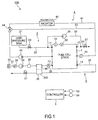
- FIG. 1 is a schematic diagram of a fuel cell system 100 according to one embodiment of the present invention.
- the fuel cell system 100 includes a fuel cell stack 1, an anode gas supply/discharge device 2, a cathode gas supply/discharge device 3, a stack cooling device 4 and a controller 5.
- the fuel cell stack 1 is formed by laminating a plurality of fuel cells, generates power by being supplied with the anode gas and the cathode gas, and supplies the generated power to various electric devices such as a motor (not shown) necessary to drive the vehicle.
- the anode gas supply/discharge device 2 includes a high pressure tank 21, an anode gas supply passage 22, an anode pressure regulating valve 23, an anode gas discharge passage 24, an anode gas recirculation passage 25, a recycle compressor 26 and a discharge valve 27.
- the high pressure tank 21 stores the anode gas to be supplied to the fuel cell stack 1 in a high pressure state.
- the anode gas supply passage 22 is a passage in which the anode gas to be supplied to the fuel cell stack 1 flows, wherein one end is connected to the high pressure tank 21 and the other end is connected to an anode gas inlet hole 11 of the fuel cell stack 1.
- the anode pressure regulating valve 23 is provided in the anode gas supply passage 22.
- the anode pressure regulating valve 23 is controlled to be open and closed by the controller 5 to adjust a pressure of the anode gas flowing out from the high pressure tank 21 to the anode gas supply passage 22 to a desired pressure.
- the anode gas discharge passage 24 is a passage in which anode off-gas discharged from the fuel cell stack 1 flows, wherein one end is connected to an anode gas outlet hole 12 of the fuel cell stack 11 and the other end is an open end.
- the anode off-gas is mixture gas of excess anode gas not used in the electrode reaction and inert gas such as nitrogen leaked from the cathode side.
- the anode gas recirculation passage 25 is a passage for returning the anode off-gas discharged to the anode gas discharge passage 24 to the anode gas supply passage 22.
- One end of the anode gas recirculation passage 25 is connected to a side of the anode gas discharge passage 24 upstream of the discharge valve 27 and the other end thereof is connected to a side of the anode gas supply passage 22 downstream of the anode pressure regulating valve 23.
- the recycle compressor 26 is provided in the anode gas recirculation passage 25.
- the recycle compressor 26 returns the anode off-gas discharged to the anode gas discharge passage 24 to the anode gas supply passage 22.
- the discharge valve 27 is provided at a position of the anode gas discharge passage 24 downstream of a connecting part of the anode gas discharge passage 24 and the anode gas recirculation passage 25.
- the discharge valve 27 is controlled to be open and closed by the controller 5 to discharge the anode off-gas and condensed water to the outside of the fuel cell system 100.
- the cathode gas supply/discharge device 3 includes a cathode gas supply passage 31, a cathode gas discharge passage 32, a filter 33, a cathode compressor 34, an air flow sensor 35, a water recovery device (hereinafter, referred to as "WRD") 36, a cathode pressure regulating valve 37, a first pressure sensor 38 and a second pressure sensor 39.
- a cathode gas supply passage 31 includes a cathode gas supply passage 31, a cathode gas discharge passage 32, a filter 33, a cathode compressor 34, an air flow sensor 35, a water recovery device (hereinafter, referred to as "WRD") 36, a cathode pressure regulating valve 37, a first pressure sensor 38 and a second pressure sensor 39.
- RDD water recovery device
- the cathode gas supply passage 31 is a passage in which the cathode gas to be supplied to the fuel cell stack 1 flows. One end of the cathode gas supply passage 31 is connected to the filter 33 and the other end thereof is connected to a cathode gas inlet hole 13 of the fuel cell stack 1.
- the cathode gas discharge passage 32 is a passage in which cathode off-gas discharged from the fuel cell stack 1 flows. One end of the cathode gas discharge passage 32 is connected to a cathode gas outlet hole 14 of the fuel cell stack 1 and the other end thereof is an open end.
- the cathode off-gas is mixture gas of the cathode gas and steam produced by the electrode reaction.
- the filter 33 removes foreign substances in the cathode gas taken into the cathode gas supply passage 31.
- the cathode compressor 34 is provided in the cathode gas supply passage 31.
- the cathode compressor 34 takes in air (outside air) as the cathode gas into the cathode gas supply passage 31 via the filter 33 and supplies it to the fuel cell stack 1.
- the air flow sensor 35 is provided downstream of the cathode compressor 34 in the cathode gas supply passage 31.
- the air flow sensor 35 detects a flow rate of the cathode gas flowing in the cathode gas supply passage 31 (hereinafter, referred to as "cathode flow rate").
- the WARD 36 is a device for recovering moisture in the cathode off-gas and humidifying the cathode gas with the recovered moisture, and includes a humidifier 361 and a dehumidifier 362.
- the humidifier 361 is provided downstream of the air flow sensor 35 in the cathode gas supply passage 31.
- the humidifier 361 humidifies the cathode gas to be supplied to the fuel cell stack 1.
- the dehumidifier 362 is provided in the cathode gas discharge passage 32.
- the dehumidifier 362 dehumidifies the cathode off-gas flowing in the cathode gas discharge passage 32 and supplies the recovered steam to the humidifier 361.
- the cathode pressure regulating valve 37 is provided downstream of the humidifier 362 of the WRD 36 in the cathode gas discharge passage 32.
- the cathode pressure regulating valve 37 is controlled to be open and closed by the controller 5 to adjust a pressure of the cathode gas to be supplied to the fuel cell stack 1 (cathode pressure) to a desired pressure.
- the first pressure sensor 38 is provided upstream of the cathode compressor 34 in the cathode gas supply passage 31 and detects the pressure of the cathode gas.
- the second pressure sensor 39 is provided downstream of the humidifier 361 of the WRD 36 in the cathode gas supply passage 31.
- the pressure sensor 39 detects the pressure of the cathode gas to be supplied to the fuel cell stack 1 (hereinafter, referred to as "cathode pressure").
- the stack cooling device 4 is a device for cooling the fuel cell stack 1 and keeping the fuel cell stack 1 at a temperature suitable for power generation.
- the stack cooling device 4 includes a cooling water circulation passage 41, a radiator 42, a bypass passage 43, a three-way valve 44, a cooling water circulation pump 45 and a water temperature sensor 46.
- the cooling water circulation passage 41 is a passage in which cooling water for cooling the fuel cell stack 11 is circulated.
- the radiator 42 is provided in the cooling water circulation passage 41.
- the radiator 42 cools cooling water discharged from the fuel cell stack 1.
- bypass passage 43 One end of the bypass passage 43 is connected to the cooling water circulation passage 41 and the other end thereof is connected to the three-way valve 44 so that the cooling water can be circulated while bypassing the radiator 42.
- the three-way valve 44 is provided downstream of the radiator 42 in the cooling water circulation passage 41.
- the three-way valve 44 switches the circulation passage for the cooling water according to the temperature of the cooling water. Specifically, when the temperature of the cooling water is relatively high, the circulation passage for the cooling water is so switched that the cooling water discharged from the fuel cell stack 1 is supplied to the fuel cell stack 1 again via the radiator 42. Conversely, when the temperature of the cooling water is relatively low, the circulation passage for the cooling water is so switched that the cooling water discharged from the fuel cell stack 1 flows along the bypass passage 43 and is supplied to the fuel cell stack 1 again without via the radiator 42.
- the cooling water circulation pump 45 is provided downstream of the three-way valve 44 in the cooling water circulation passage 41 to circulate the cooling water.
- the water temperature sensor 46 is provided upstream of the radiator 42 in the cooling water circulation passage 41.
- the water temperature sensor 46 detects the temperature of the cooling water discharged from the fuel cell stack 1 (hereinafter, referred to as "stack temperature").
- the controller 5 is configured by a microcomputer including a central processing unit (CPU), a read only memory (ROM), a random access memory (RAM) and an input/output interface (I/O interface).
- CPU central processing unit
- ROM read only memory
- RAM random access memory
- I/O interface input/output interface
- signals from various sensors necessary to control the fuel cell system 100 such as a current sensor 51 for detecting an output current of the fuel cell stack 1, a voltage sensor 52 for detecting an output voltage of the fuel cell stack 1 and an accelerator stroke sensor 53 for detecting a depressed amount of an accelerator pedal besides the aforementioned air flow sensor 35, first pressure sensor 38, second pressure sensor 39 and water temperature sensor 46 are input.
- the controller 5 calculates power necessary to drive the vehicle based on the detection signals of these various sensors (hereinafter, referred to as “required output power").
- the controller 5 controls an internal moisture content of the fuel cell stack 1 by controlling the cathode flow rate, the cathode pressure and the stack temperature so that an electrolyte membrane of each fuel cell constituting the fuel cell stack 1 achieves a predetermined wet state where the electrolyte membrane is appropriately humidified.
- the wet state of the electrolyte membrane is known to be correlated with an internal high frequency resistance (HFR) (hereinafter, referred to as "internal resistance") of the fuel cell stack 1.
- HFR high frequency resistance
- the controller 5 controls the internal moisture content of the fuel cell stack 1 by controlling the cathode flow rate, the cathode pressure and the stack temperature so that the internal resistance of the fuel cell stack 1 reaches a predetermined target internal resistance.
- the cathode flow rate needs to be above a minimum flow rate necessary to make the output power of the fuel cell stack 1 reach at least the required output power (hereinafter, referred to as "minimum cathode flow rate").
- minimum cathode flow rate a minimum flow rate necessary to make the output power of the fuel cell stack 1 reach at least the required output power
- cathode flow rate detection accuracy by the air flow sensor 35 tends to decrease with a decrease in the cathode flow rate, it has not been possible to actually reduce the cathode flow rate to the minimum cathode flow rate in an attempt to reduce the cathode flow rate to the minimum cathode flow rate. That is, the cathode flow rate can be reduced only to a flow rate, which is the minimum cathode flow rate plus a sufficient margin, thereby causing a problem of degrading fuel economy.
- the cathode pressure and the stack temperature are controlled to adjust the internal resistance to the target internal resistance according to need while the cathode flow rate is accurately estimated and the cathode compressor 34 is controlled so that the estimated cathode flow rate does not fall below the minimum cathode flow rate.
- a method for estimating the cathode flow rate according to the present embodiment is described below with reference to FIGS. 2 to 4 .
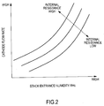
- FIG. 2 is a graph showing the cathode flow rate necessary to maintain the internal resistance of the fuel cell stack 1 at a certain fixed value in relation to a stack entrance humidity of the cathode gas.
- the cathode flow rate necessary to maintain the internal resistance at the certain fixed value increases with an increase in the stack entrance humidity of the cathode gas. Further, if the stack entrance humidity of the cathode gas is the same, the necessary cathode flow rate increases with an increase in the value at which the internal resistance is maintained.
- the cathode flow rate needs to be increased to dry the electrolyte membrane as the stack entrance humidity increases.
- FIG. 3 is a graph showing the cathode flow rate when each of the cathode pressure, the stack temperature and an atmospheric humidity indicates a certain fixed value in relation to the stack entrance humidity of the cathode gas.
- the stack entrance humidity of the cathode gas increases as the cathode flow rate decreases. Further, if the cathode flow rate is the same, the stack entrance humidity of the cathode gas increases as the cathode pressure increases, as the stack temperature decreases or as the atmospheric humidity increases. That is, the stack entrance humidity of the cathode gas increases as each of the parameters, i.e. the cathode pressure, the stack temperature and the atmospheric humidity changes to increase the internal moisture content of the fuel cell stack 1.
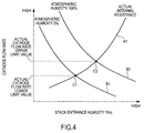
- FIG. 4 is a graph showing a method for estimating the cathode flow rate based on the cathode pressure, the stack temperature and the internal resistance.
- the atmospheric humidity is not detected.
- a solid line A1 shown in FIG. 4 can be drawn by obtaining a relationship of FIG. 2 described above by an experiment or the like in advance.
- the solid line A1 is a line representing the cathode flow rate estimated from the detected current internal resistance (hereinafter, referred to as "actual internal resistance") in relation to the stack entrance humidity of the cathode gas.
- a solid line B1 shown in FIG. 4 when the atmospheric humidity is assumed to be 0 % and a solid line B2 shown in FIG. 4 when the atmospheric humidity is assumed to be 100 % can be drawn by obtaining a relationship of FIG. 3 described above by an experiment or the like in advance even if the atmospheric humidity is not known.
- the solid line B1 is a line representing the cathode flow rate estimated from the detected cathode pressure and stack temperature when the atmospheric humidity is assumed to be 0 % in relation to the stack entrance humidity of the cathode gas.
- the solid line B2 is a line representing the cathode flow rate estimated from the detected cathode pressure and stack temperature when the atmospheric humidity is assumed to be 100 % in relation to the stack entrance humidity of the cathode gas.
- actual cathode flow rate (hereinafter, referred to as “actual cathode flow rate”) can be estimated at least between the cathode flow rate at an intersection C1 of the solid lines A1, B1 (hereinafter, referred to as “actual cathode flow rate lower limit value”) and the cathode flow rate at an intersection C2 of the solid lines A1, B2 (hereinafter, referred to as “actual cathode flow rate upper limit value").
- the cathode compressor 34 is so controlled that the actual cathode flow rate lower limit value does not fall below the minimum cathode flow rate, at least the actual cathode flow rate does not fall below the minimum cathode flow rate.
- the actual cathode flow rate lower limit value is basically set as a cathode flow rate estimated value and the cathode pressure and the stack temperature are controlled to adjust the internal resistance to the target internal resistance according to need while the cathode compressor 34 is so controlled that the actual cathode flow rate lower limit value does not fall below the minimum cathode flow rate.
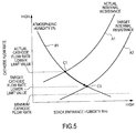
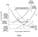
- FIGS. 5 and 6 are graphs showing the wet control of the electrolyte membrane when the actual internal resistance is higher than the target internal resistance.
- a solid line A2 is a line representing the cathode flow rate necessary to maintain the internal resistance at the target internal resistance in relation to the stack entrance humidity of the cathode gas.
- a solid line A1 is a line representing the cathode flow rate estimated from the detected current internal resistance (hereinafter, referred to as "actual internal resistance") in relation to the stack entrance humidity of the cathode gas as in FIG. 4 .
- a solid line B1 is a line representing the cathode flow rate estimated from the detected cathode pressure and stack temperature when the atmospheric humidity is assumed to be 0 % in relation to the stack entrance humidity of the cathode gas as in FIG. 4 .
- target cathode flow rate lower limit value the actual internal resistance can be converged to the target internal resistance by controlling the cathode compressor 34 such that the cathode flow rate is reduced by a difference between the actual cathode flow rate lower limit value and the target cathode flow rate lower limit value.
- the cathode flow rate can be reduced only to the minimum cathode flow rate without being able to be reduced to the target cathode flow rate lower limit value. This is because the output power falls below the required output power if the cathode flow rate is reduced to the target cathode flow rate lower limit value when the target cathode flow rate lower limit value is smaller than the minimum cathode flow rate.
- the internal resistance is converged to the target internal resistance by controlling one or both of the cathode pressure and the stack temperature after the cathode compressor 34 is controlled to reduce the cathode flow rate by the difference between the actual cathode flow rate lower limit value and the minimum cathode flow rate.
- the solid line B1 is moved to a solid line B1' by increasing the cathode pressure or decreasing the stack temperature, thereby converging the internal resistance to the target internal resistance.
- the solid line B1' is a line on which the cathode flow rate at an intersection C4 of the solid lines A2, B1' is the minimum cathode flow rate.
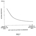
- FIG. 7 is a graph showing a relationship between the wet state of the electrolyte membrane and the internal resistance.
- the internal resistance of the fuel cell stack 1 changes according to the wet state of the electrolyte membrane.
- the drier the electrolyte membrane the higher the internal resistance.
- An amount of change of the internal resistance according to a change in the wet state of the electrolyte membrane is larger when a degree of wetness of the electrolyte membrane is low, i.e. when the electrolyte membrane is relatively dry.
- the amount of change of the internal resistance when the wet state of the electrolyte membrane changes is smaller when the degree of wetness of the electrolyte membrane is high, i.e. when the electrolyte membrane is relatively wet.
- estimation accuracy may fall if the cathode flow rate is estimated based on the cathode pressure, the stack temperature and the actual internal resistance when the electrolyte membrane is relatively wet and the actual internal resistance is low.
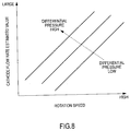
- a map of FIG. 8 is exceptionally referred to and the cathode flow rate is estimated based on a rotation speed of the cathode compressor 34 and a differential pressure before and after the cathode compressor 34 when the actual internal resistance is lower than the target internal resistance.
- FIG. 8 is the map for estimating the cathode flow rate based on the rotation speed of the cathode compressor 34 and the differential pressure before and after the cathode compressor 34.
- the cathode flow rate estimated value increases as the rotation speed of the cathode compressor 34 increases and as the differential pressure before and after the cathode compressor 34 increases.
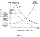
- FIGS. 9 and 10 are graphs showing the wet control of the electrolyte membrane when the actual internal resistance is lower than the target internal resistance.
- a solid line A2 is a line representing the cathode flow rate necessary to maintain the internal resistance at the target internal resistance in relation to the stack entrance humidity of the cathode gas as in FIG. 5 .
- a solid line B1 is a line representing the cathode flow rate estimated from the detected cathode pressure and stack temperature when the atmospheric humidity is assumed to be 0 % in relation to the stack entrance humidity of the cathode gas as in FIG. 4 .
- the cathode compressor 34 is so controlled as to increase the cathode flow rate by a difference between the minimum cathode flow rate and an estimated value of the cathode flow rate estimated based on the rotation speed of the cathode compressor 34 and the differential pressure before and after the cathode compressor 34 (hereinafter, referred to as "cathode flow rate estimated value").
- the solid line B1 is moved to a solid line B1' by increasing the cathode pressure or decreasing the stack temperature, thereby converging the internal resistance to the target internal resistance.
- the cathode compressor 34 is so controlled as to increase the cathode flow rate by the difference between the minimum cathode flow rate and the cathode flow rate estimated value. Thereafter, the solid line B1 is moved to the solid line B1' by decreasing the cathode pressure or increasing the stack temperature, thereby converging the internal resistance to the target internal resistance.
- FIG. 11 is a flow chart showing the wet control of the electrolyte membrane according to the present embodiment.
- Step S1 the controller 5 reads detection signals of various sensors and detects an operating state of the fuel cell system 100.
- Step S2 the controller 5 calculates the required output power based on the operating state of the fuel cell system 100.
- Step S3 the controller 5 calculates the minimum cathode flow rate based on the required output power.
- the minimum cathode flow rate decreases as the required output power decreases.
- Step S4 the controller 5 detects the actual internal resistance of the fuel cell stack 1. Specifically, an alternating current is superimposed on an output current of the fuel cell stack 1 by controlling, for example, a DC/DC converter (not shown) or the like, and detects a voltage value of the fuel cell stack 11 at that time by a voltage sensor. A voltage amplitude of the superimposed alternating current is computed based on the voltage value and the internal resistance of the fuel cell is computed by dividing the voltage amplitude by a current amplitude of the superimposed alternating current.
- a DC/DC converter not shown
- Step S5 the controller 5 calculates the actual cathode flow rate lower limit value based on the cathode pressure, the stack temperature and the actual internal resistance.
- Step S6 the controller 5 calculates the target cathode flow rate lower limit value based on the cathode pressure, the stack temperature and the predetermined target internal resistance set in advance.
- Step S7 the controller 5 determines whether or not the actual internal resistance and the target internal resistance are equal. Specifically, if an absolute value of a difference between the actual internal resistance and the target internal resistance is not larger than a predetermined value, the actual internal resistance and the target internal resistance are determined to be equal. If the actual internal resistance and the target internal resistance are equal, the controller 5 finishes the process this time. On the other hand, a processing of Step S8 is performed unless the actual internal resistance and the target internal resistance are equal.
- Step S8 the controller 5 performs an electrolyte membrane wet control process.
- the electrolyte membrane wet control process is described in detail below with reference to FIG. 12 .
- FIG. 12 is a flow chart showing the electrolyte membrane wet control process.
- Step S81 the controller 5 determines whether or not the actual internal resistance is higher than the target internal resistance.
- the controller 5 performs a processing of Step S82 if the actual internal resistance is higher than the target internal resistance.
- Step S86 a processing of Step S86 is performed if the actual internal resistance is not higher than the target internal resistance.
- Step S82 the controller 5 determines whether or not the target cathode flow rate lower limit value is not smaller than the minimum cathode flow rate.
- the controller 5 performs a processing of Step S83 if the target cathode flow rate lower limit value is not smaller than the minimum cathode flow rate.
- a processing of Step S84 is performed if the target cathode flow rate lower limit value is smaller than the minimum cathode flow rate.
- Step S83 the controller 5 controls the cathode compressor 34 to reduce the cathode flow rate by the difference between the actual cathode flow rate lower limit value and the target cathode flow rate lower limit value. This causes the internal resistance to converge to the target internal resistance (see FIG. 5 ).
- Step S84 the controller 5 controls the cathode compressor 34 to reduce the cathode flow rate by a difference between the actual cathode flow rate lower limit value and the minimum cathode flow rate (see FIG. 6 ).
- Step S85 the controller 5 controls one or both of the cathode pressure and the stack temperature so that the internal resistance becomes the target internal resistance. Specifically, the cathode pressure is increased in the case of controlling the cathode pressure and the stack temperature is decreased in the case of controlling the stack temperature. This causes the internal resistance to converge to the target internal resistance (see FIG. 6 ).
- Step S86 the controller 5 refers to the map of FIG. 9 and calculates the cathode flow rate estimated value based on the rotation speed of the cathode compressor 34 and the differential pressure before and after the cathode compressor 34.
- Step S87 the controller 5 controls the cathode compressor 34 to increase the cathode flow rate by the difference between the minimum cathode flow rate and the cathode flow rate estimated value (see FIGS. 8 and 9 ).
- Step S88 the controller 5 determines whether or not the minimum cathode flow rate is higher than the target cathode flow rate lower limit value.
- the controller 5 performs a processing of Step S89 if the minimum cathode flow rate is higher than the target cathode flow rate lower limit value.
- a processing of Step S90 is performed if the minimum cathode flow rate is not higher than the target cathode flow rate.
- Step S89 the controller 5 controls one or both of the cathode pressure and the stack temperature so that the internal resistance becomes the target internal resistance. Specifically, the cathode pressure is increased in the case of controlling the cathode pressure and the stack temperature is decreased in the case of controlling the stack temperature (see FIG. 8 ).
- Step S90 the controller 5 controls one or both of the cathode pressure and the stack temperature so that the internal resistance becomes the target internal resistance. Specifically, the cathode pressure is decreased in the case of controlling the cathode pressure and the stack temperature is increased in the case of controlling the stack temperature (see FIG. 9 ).
- the cathode flow rate can be reduced only to the flow rate, which is the minimum cathode flow rate plus the sufficient margin, due to the influence of the detection accuracy of the air flow sensor 35.
- a minimum value of the flow rate considered to be the current cathode flow rate i.e. the actual cathode flow rate lower limit value is calculated based on the cathode pressure, the stack temperature and the internal resistance, and the calculated value is set as the cathode flow rate estimated value.
- the cathode flow rate can be reduced to a flow rate closer to the minimum cathode flow rate as compared with the case of executing the control to prevent the cathode flow rate detected by the air flow sensor 35 from falling below the minimum cathode flow rate.
- the cathode compressor 34 can be operated at low rotation, wherefore the fuel economy of the fuel cell system 100 can be improved.
- the cathode pressure and the stack temperature are controlled to adjust the internal resistance to the target internal resistance according to need while the cathode compressor 34 is controlled to prevent the actual cathode flow rate lower limit value from falling below the minimum cathode flow rate determined according to the operating state of the fuel cell system 100.
- the power generation efficiency of the fuel cell system 100 can be improved.
- the cathode flow rate is estimated based on the rotation speed of the cathode compressor 34 and the differential pressure before and after the cathode compressor 34 when the internal resistance of the fuel cell stack 1 is higher than a predetermined value and estimation accuracy when the cathode flow rate is estimated based on the cathode pressure, the stack temperature and the internal resistance may fall.
- the cathode flow rate can be reliably prevented from falling below the minimum cathode flow rate and the cathode compressor 34 can be operated at low rotation, wherefore the fuel economy of the fuel cell system 100 can be improved.
- the cathode compressor 34 is feedback-controlled using an estimated cathode flow rate instead of the cathode flow rate detected by the air flow sensor 35 in a region where the detection accuracy of the air flow sensor 35 is low. It should be noted that, in the following embodiment, components having functions similar to those of the first embodiment described above are denoted by the same reference signs and repeated description is omitted as appropriate.
- the detection accuracy of the air flow sensor 35 tends to decrease with a decrease in the cathode flow rate.
- the cathode compressor 34 is feedback-controlled using the estimated cathode flow rate in the region where the detection accuracy of the air flow sensor 35 is low, i.e. the cathode flow rate detected by the air flow sensor 35 is below a predetermined flow rate.
- the cathode compressor 34 is feedback-controlled based on the estimated cathode flow rate and a target value of the cathode gas to be supplied to the fuel cell stack 1 (hereinafter, referred to as "target cathode flow rate") so that the estimated cathode flow rate becomes the target cathode flow rate.
- the cathode compressor 34 is feedback-controlled based on the cathode flow rate detected by the air flow sensor 35 and the target cathode flow rate so that the detected cathode flow rate becomes the target cathode flow rate.
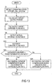
- a control of the cathode compressor 34 according to this embodiment is described below with reference to a flow chart of FIG. 13 .
- FIG. 13 is the flow chart showing the control of the cathode compressor 34 according to this embodiment.
- Step S21 the controller 5 calculates the target cathode flow rate based on the operating state of the fuel cell system 100.
- the target cathode flow rate is a flow rate capable of also preventing flooding while satisfying target output power.
- Step S22 the controller 5 sets an actual cathode flow rate lower limit value calculated based on the cathode pressure, the stack temperature and the actual internal resistance as an estimated value of the cathode flow rate.
- Step S23 the controller 5 determines whether or not the cathode flow rate detected by the air flow sensor 35 is below the predetermined flow rate.
- the controller 5 performs a processing of S24 if the cathode flow rate detected by the air flow sensor 35 is below the predetermined flow rate.
- a processing of Step S25 is performed if the cathode flow rate detected by the air flow sensor 35 is not below the predetermined flow rate.
- Step S24 the controller 5 feedback-controls the cathode compressor 34 based on the estimated value of the cathode flow rate and the target cathode flow rate so that the estimated value of the cathode flow rate becomes the target cathode flow rate.
- Step S25 the controller 5 feedback-controls the cathode compressor 34 based on the cathode flow rate detected by the air flow sensor 35 and the target cathode flow rate so that the detected cathode flow rate becomes the target cathode flow rate.
- the cathode compressor 34 is feedback-controlled toward the target cathode flow rate using the more accurate estimated cathode flow rate instead of the cathode flow rate detected by the air flow sensor 35 in the region where the detection accuracy of the air flow sensor 35 is low.
- the cathode compressor 34 can be operated at low rotation and the fuel economy of the fuel cell system 100 can be improved.
- the cathode flow rate is estimated according to the operating state of the cathode compressor 34 in such a case.
- the cathode flow rate may be estimated based on the cathode pressure, the stack temperature and the actual internal resistance regardless of the magnitude of the actual internal resistance by correcting to increase the minimum cathode flow rate with a decrease in the actual internal resistance.
- the cathode flow rate is estimated based on the cathode pressure, the stack temperature and the actual internal resistance, assuming that the atmospheric humidity is 0 %.
- the estimated cathode flow rate may be corrected according to a detection value of the humidity sensor. Specifically, the estimated cathode flow rate may be corrected to increase with an increase in the atmospheric humidity. This enables the cathode flow rate to be estimated with higher accuracy.
- the wet control of the electrolyte membrane may be executed only in the region where the detection accuracy of the air flow sensor 35 is low.
Landscapes
- Life Sciences & Earth Sciences (AREA)
- Engineering & Computer Science (AREA)
- Manufacturing & Machinery (AREA)
- Sustainable Development (AREA)
- Sustainable Energy (AREA)
- Chemical & Material Sciences (AREA)
- Chemical Kinetics & Catalysis (AREA)
- Electrochemistry (AREA)
- General Chemical & Material Sciences (AREA)
- Fuel Cell (AREA)
Claims (11)
- Brennstoffzellensystem (100), das so ausgeführt ist, dass es Strom erzeugt, indem es einer Brennstoffzelle (1) Anodengas und Kathodengas zuführt, wobei es umfasst:eine Kathodengas-Zuführeinheit (34), die so ausgeführt ist, dass sie der Brennstoffzelle (1) das Kathodengas zuführt,eine Kathodendruck-Erfassungseinheit (39), die so ausgeführt ist, dass sie einen Druck des der Brennstoffzelle (1) zuzuführenden Kathodengases erfasst;eine Brennstoffzetten-Temperaturerfassungseinheit (46), die so ausgeführt ist, dass sie eine Temperatur der Brennstoffzelle (1) erfasst;ein eine en Innenwiderstands-Erfassungseinheit (5), die so eingerichtet ist, dass sie einen Innenwiderstand der Brennstoffzelle (1) erfasst;eine Einheit (5) zur Berechnung einer Kathoden-Sollströmungsgeschwindigkeit, die so ausgeführt ist, dass sie eine Kathoden-Sollströmungsgeschwindigkeit, die für Zufuhr zu der Brennstoffzelle (1) erforderlich ist, auf Basis eines Betriebszustandes des Brennstoffzellensystems (100) berechnet;eine Einheit (5) zur Schätzung einer Kathoden-Strömungsgeschwindigkeit, die so ausgeführt ist, dass sie eine Strömungsgeschwindigkeit des Kathodengases entsprechend dem Druck des Kathodengases, der Temperatur der Brennstoffzelle (1) und des Innenwiderstandes der Brennstoffzelle (1) schätzt; undeine Einheit (5) zur Steuerung der Kathoden-Strömungsgeschwindigkeit, die so ausgeführt ist, dass sie die Kathodengas-Zuführeinheit (34) so steuert, dass die geschätzte Strömungsgeschwindigkeit des Kathodengases näher an der Kathoden-Sollströmungsgeschwindigkeit liegt.
- Brennstoffzellensystem (100) nach Anspruch 1, wobei die Einheit (5) zur Schätzung der Kathoden-Strömungsgeschwindigkeit einen Schätzwert der Strömungsgeschwindigkeit des Kathodengases mit einer Zunahme des Innenwiderstandes der Brennstoffzelle (1) erhöht.
- Brennstoffzellensystem (100) nach Anspruch 1 oder 2, wobei die Einheit (5) zur Schätzung der Kathoden-Strömungsgeschwindigkeit einen Schätzwert der Strömungsgeschwindigkeit des Kathodengases mit einer Zunahme des Drucks des Kathodengases erhöht.
- Brennstoffzellensystem (100) nach einem der Ansprüche 1 bis 3, wobei die Einheit (5) zur Schätzung der Kathoden-Strömungsgeschwindigkeit einen Schätzwert der Strömungsgeschwindigkeit des Kathodengases mit einer Abnahme der Temperatur der Brennstoffzelle (1) erhöht.
- Brennstoffzellensystem (100) nach einem der Ansprüche 1 bis 4, wobei die Einheit (5) zur Schätzung der Kathoden-Strömungsgeschwindigkeit die Strömungsgeschwindigkeit des Kathodengases unter der Voraussetzung schätzt, dass eine Luftfeuchtigkeit einer äußeren Umgebung, in der die Brennstoffzelle (1) eingesetzt wird, einen minimalen Wert hat.
- Brennstoffzellensystem (100) nach einem der Ansprüche 1 bis 4, die eine Luftfeuchtigkeits-Erfassungseinheit (5) umfasst, die so ausgeführt ist, dass sie eine Luftfeuchtigkeit erfasst, wobei:die Einheit (5) zur Schätzung der Kathoden-Strömungsgeschwindigkeit einen Schätzwert der Strömungsgeschwindigkeit des Kathodengases, der entsprechend dem Druck des Kathodengases, der Temperatur der Brennstoffzelle (1) und dem Innenwiderstand der Brennstoffzelle (1) geschätzt wird, Korrektur so ausführt, dass er mit einer Zunahme der Luftfeuchtigkeit erhöht wird.
- Brennstoffzellensystem (100) nach einem der Ansprüche 1 bis 6, die eine Einheit (5) zur Steuerung des Innenwiderstandes umfasst, die so ausgeführt ist, dass sie den Innenwiderstand der Brennstoffzelle (1) auf einen vorgegebenen Soll-Innenwiderstand erhöht, wobei:die Einheit (5) zur Steuerung des Innenwiderstandes den Innenwiderstand der Brennstoffzelle (1) auf den vorgegebenen Soll-Innenwiderstand erhöht, indem sie den Druck des Kathodengases erhöht, wenn der Innenwiderstand der Brennstoffzelle (1) höher ist als der Soll-Innenwiderstand und die geschätzte Strömungsgeschwindigkeit des Kathodengases und die Kathoden-Sollströmungsgeschwindigkeit gleich sind.
- Brennstoffzellensystem (100) nach einem der Ansprüche 1 bis 6, die eine Einheit (5) zur Steuerung des Innenwiderstandes umfasst, die so ausgeführt ist, dass sie den Innenwiderstand der Brennstoffzelle (1) auf einen vorgegebenen Soll-Innenwiderstand erhöht, wobei:die Einheit (5) zur Steuerung des Innenwiderstandes den Innenwiderstand der Brennstoffzelle (1) auf den vorgegebenen Soll-Innenwiderstand erhöht, indem sie die Temperatur der Brennstoffzelle (1) verringert, wenn der Innenwiderstand der Brennstoffzelle (1) höher ist als der Soll-Innenwiderstand und die geschätzte Strömungsgeschwindigkeit des Kathodengases und die Kathoden-Sollströmungsgeschwindigkeit gleich sind.
- Brennstoffzellensystem (100) nach einem der Ansprüche 1 bis 8, wobei die Einheit (5) zur Schätzung der Kathoden-Strömungsgeschwindigkeit die Strömungsgeschwindigkeit des Kathodengases entsprechend dem Druck des Kathodengases, der Temperatur der Brennstoffzelle (1) sowie dem Innenwiderstand der Brennstoffzelle (1) schätzt, wenn der Innenwiderstand der Brennstoffzelle (1) höher ist als ein vorgegebener Wert; und
die Strömungsgeschwindigkeit des Kathodengases auf Basis einer Drehgeschwindigkeit eines Kompressors, mit dem das Kathodengas der Brennstoffzelle (1) unter Druck zugeführt wird, sowie eines Differenzdrucks vor und hinter dem Kompressor schätzt, wenn der Innenwiderstand der Brennstoffzelle (1) niedriger ist als der vorgegebene Wert. - Brennstoffzellensystem (100) nach einem der Ansprüche 1 bis 7, wobei die Einheit (5) zur Berechnung der Kathoden-Sollströmungsgeschwindigkeit Korrektur so ausführt, dass sie die minimale Kathoden-Strömungsgeschwindigkeit mit einer Zunahme des Innenwiderstandes der Brennstoffzelle (1) erhöht.
- Brennstoffzellensystem (100) nach einem der Ansprüche 1 bis 10, die eine Einheit (35) zur Erfassung einer Kathoden-Strömungsgeschwindigkeit umfasst, die so ausgeführt ist, dass sie eine Strömungsgeschwindigkeit des der Brennstoffzelle (1) zuzuführenden Kathodengases erfasst, wobei:die Einheit (5) zur Steuerung der Kathoden-Strömungsgeschwindigkeit die Kathodengas-Zuführeinheit (34) auf Basis der Kathoden-Sollströmungsgeschwindigkeit sowie der geschätzten Strömungsgeschwindigkeit des Kathodengases steuert, wenn die Strömungsgeschwindigkeit des Kathodengases niedriger ist als eine vorgegebene Strömungsgeschwindigkeit.
Applications Claiming Priority (2)
| Application Number | Priority Date | Filing Date | Title |
|---|---|---|---|
| JP2012002278 | 2012-01-10 | ||
| PCT/JP2013/050261 WO2013105590A1 (ja) | 2012-01-10 | 2013-01-10 | 燃料電池システム |
Publications (4)
| Publication Number | Publication Date |
|---|---|
| EP2804246A1 EP2804246A1 (de) | 2014-11-19 |
| EP2804246A4 EP2804246A4 (de) | 2015-07-29 |
| EP2804246B1 true EP2804246B1 (de) | 2016-09-14 |
| EP2804246B8 EP2804246B8 (de) | 2016-10-19 |
Family
ID=48781534
Family Applications (1)
| Application Number | Title | Priority Date | Filing Date |
|---|---|---|---|
| EP13736353.7A Not-in-force EP2804246B8 (de) | 2012-01-10 | 2013-01-10 | Brennstoffzellensystem |
Country Status (6)
| Country | Link |
|---|---|
| US (1) | US9350033B2 (de) |
| EP (1) | EP2804246B8 (de) |
| JP (1) | JP5812118B2 (de) |
| CN (1) | CN104040771B (de) |
| CA (1) | CA2860966C (de) |
| WO (1) | WO2013105590A1 (de) |
Families Citing this family (8)
| Publication number | Priority date | Publication date | Assignee | Title |
|---|---|---|---|---|
| JP6229731B2 (ja) * | 2013-10-01 | 2017-11-15 | 日産自動車株式会社 | 燃料電池システム |
| JP6003878B2 (ja) | 2013-12-25 | 2016-10-05 | トヨタ自動車株式会社 | 燃料電池システム |
| US10164275B2 (en) * | 2014-03-13 | 2018-12-25 | Nissan Motor Co., Ltd. | Fuel cell system |
| KR102028620B1 (ko) * | 2014-08-11 | 2019-10-04 | 존슨 아이피 홀딩 엘엘씨 | 열-전기화학적 변환기 |
| WO2016125231A1 (ja) * | 2015-02-02 | 2016-08-11 | 日産自動車株式会社 | 燃料電池システム及び燃料電池システムの制御方法 |
| KR102552146B1 (ko) | 2018-04-05 | 2023-07-05 | 현대자동차주식회사 | 연료전지 시스템의 운전 제어 장치 및 방법 |
| DE102022103159A1 (de) | 2022-02-10 | 2023-08-10 | Bayerische Motoren Werke Aktiengesellschaft | Verfahren und Vorrichtung zur Ermittlung des Oxidationsmittel-Massenstroms in einen Energiewandler |
| KR102672284B1 (ko) | 2022-06-21 | 2024-06-03 | 주식회사 엘지에너지솔루션 | 배터리 관리 장치 및 방법 |
Family Cites Families (13)
| Publication number | Priority date | Publication date | Assignee | Title |
|---|---|---|---|---|
| JP3894026B2 (ja) * | 2001-05-18 | 2007-03-14 | 株式会社デンソー | 燃料電池内部の水分測定方法 |
| JP3905800B2 (ja) * | 2002-07-17 | 2007-04-18 | 本田技研工業株式会社 | 燃料電池の保護装置 |
| JP4751608B2 (ja) | 2004-12-24 | 2011-08-17 | アイシン精機株式会社 | カソード用ポンプまたはブロアの制御装置、および燃料電池システム |
| JP4457942B2 (ja) | 2005-04-01 | 2010-04-28 | 株式会社デンソー | 燃料電池システム |
| US7862935B2 (en) * | 2005-05-17 | 2011-01-04 | Gm Global Technology Operations, Inc. | Management via dynamic water holdup estimator in a fuel cell |
| JP5009168B2 (ja) * | 2006-01-13 | 2012-08-22 | パナソニック株式会社 | 燃料電池システム及び燃料電池システムの運転方法 |
| JP5011733B2 (ja) * | 2006-01-23 | 2012-08-29 | 日産自動車株式会社 | 燃料電池システム及び燃料電池の加湿状態判定方法 |
| JP5094202B2 (ja) * | 2007-05-14 | 2012-12-12 | アイシン精機株式会社 | 流体送出装置、改質器および燃料電池システム |
| JP2008305700A (ja) * | 2007-06-08 | 2008-12-18 | Honda Motor Co Ltd | 燃料電池システム |
| JP5080876B2 (ja) * | 2007-06-20 | 2012-11-21 | 本田技研工業株式会社 | 燃料電池システム |
| JP2009211935A (ja) * | 2008-03-04 | 2009-09-17 | Nissan Motor Co Ltd | 燃料電池システム |
| JP5509728B2 (ja) * | 2009-08-24 | 2014-06-04 | 日産自動車株式会社 | 燃料電池システム |
| US8932775B2 (en) * | 2010-05-28 | 2015-01-13 | Toyota Jidosha Kabushiki Kaisha | Method and apparatus for controlling the operation of a fuel cell |
-
2013
- 2013-01-10 EP EP13736353.7A patent/EP2804246B8/de not_active Not-in-force
- 2013-01-10 CN CN201380005206.7A patent/CN104040771B/zh not_active Expired - Fee Related
- 2013-01-10 JP JP2013553302A patent/JP5812118B2/ja not_active Expired - Fee Related
- 2013-01-10 CA CA2860966A patent/CA2860966C/en active Active
- 2013-01-10 US US14/371,103 patent/US9350033B2/en not_active Expired - Fee Related
- 2013-01-10 WO PCT/JP2013/050261 patent/WO2013105590A1/ja not_active Ceased
Also Published As
| Publication number | Publication date |
|---|---|
| CA2860966C (en) | 2017-01-03 |
| US20150004506A1 (en) | 2015-01-01 |
| US9350033B2 (en) | 2016-05-24 |
| WO2013105590A1 (ja) | 2013-07-18 |
| CN104040771B (zh) | 2016-08-17 |
| JPWO2013105590A1 (ja) | 2015-05-11 |
| EP2804246A1 (de) | 2014-11-19 |
| EP2804246A4 (de) | 2015-07-29 |
| EP2804246B8 (de) | 2016-10-19 |
| CA2860966A1 (en) | 2013-07-18 |
| CN104040771A (zh) | 2014-09-10 |
| JP5812118B2 (ja) | 2015-11-11 |
Similar Documents
| Publication | Publication Date | Title |
|---|---|---|
| EP2804246B1 (de) | Brennstoffzellensystem | |
| US9105889B2 (en) | Method and apparatus for determining humidity states of individual cells in a fuel cell, method and apparatus for controlling humidity states of individual cells in a fuel cell, and a fuel cell system | |
| CA2876576C (en) | A fuel cell system with oxidant flow rate control | |
| EP2720306B1 (de) | Nasszustands-regelungsvorrichtung für eine brennstoffzelle | |
| CA2907894C (en) | Fuel cell with intercooler egress temperature control | |
| JP2013258111A (ja) | 燃料電池システム | |
| US10230118B2 (en) | Method for controlling fuel cell system | |
| CA2942629C (en) | Fuel cell system with wetness control | |
| JP2005158647A (ja) | 燃料電池の制御装置 | |
| US10050292B2 (en) | Method for controlling fuel cell system | |
| JP2014007097A (ja) | 燃料電池システム | |
| JP6136185B2 (ja) | 燃料電池システム | |
| JP2022132887A (ja) | 燃料電池システム | |
| JP2008071539A (ja) | 燃料電池システム及び燃料電池スタックの流体配分方法 | |
| JP2006120340A (ja) | 燃料電池の反応ガス供給装置および反応ガス供給方法 | |
| JP5223624B2 (ja) | 燃料電池システム及びそれを用いた燃料電池システムの制御方法 | |
| JP5910421B2 (ja) | 燃料電池システム | |
| JP2008257932A (ja) | 燃料電池システム | |
| WO2014192649A1 (ja) | 燃料電池システム及び燃料電池システムの制御方法 |
Legal Events
| Date | Code | Title | Description |
|---|---|---|---|
| PUAI | Public reference made under article 153(3) epc to a published international application that has entered the european phase |
Free format text: ORIGINAL CODE: 0009012 |
|
| 17P | Request for examination filed |
Effective date: 20140806 |
|
| AK | Designated contracting states |
Kind code of ref document: A1 Designated state(s): AL AT BE BG CH CY CZ DE DK EE ES FI FR GB GR HR HU IE IS IT LI LT LU LV MC MK MT NL NO PL PT RO RS SE SI SK SM TR |
|
| DAX | Request for extension of the european patent (deleted) | ||
| RA4 | Supplementary search report drawn up and despatched (corrected) |
Effective date: 20150701 |
|
| RIC1 | Information provided on ipc code assigned before grant |
Ipc: H01M 8/10 20060101ALI20150625BHEP Ipc: H01M 8/04 20060101AFI20150625BHEP |
|
| GRAP | Despatch of communication of intention to grant a patent |
Free format text: ORIGINAL CODE: EPIDOSNIGR1 |
|
| INTG | Intention to grant announced |
Effective date: 20160530 |
|
| GRAS | Grant fee paid |
Free format text: ORIGINAL CODE: EPIDOSNIGR3 |
|
| GRAA | (expected) grant |
Free format text: ORIGINAL CODE: 0009210 |
|
| GRAT | Correction requested after decision to grant or after decision to maintain patent in amended form |
Free format text: ORIGINAL CODE: EPIDOSNCDEC |
|
| AK | Designated contracting states |
Kind code of ref document: B1 Designated state(s): AL AT BE BG CH CY CZ DE DK EE ES FI FR GB GR HR HU IE IS IT LI LT LU LV MC MK MT NL NO PL PT RO RS SE SI SK SM TR |
|
| REG | Reference to a national code |
Ref country code: GB Ref legal event code: FG4D |
|
| REG | Reference to a national code |
Ref country code: CH Ref legal event code: EP |
|
| RIN2 | Information on inventor provided after grant (corrected) |
Inventor name: KAGAMI, FUMIO Inventor name: TOMITA, YOUSUKE Inventor name: IKEZOE, KEIGO |
|
| RAP2 | Party data changed (patent owner data changed or rights of a patent transferred) |
Owner name: NISSAN MOTOR CO., LTD. |
|
| REG | Reference to a national code |
Ref country code: IE Ref legal event code: FG4D |
|
| RAP2 | Party data changed (patent owner data changed or rights of a patent transferred) |
Owner name: NISSAN MOTOR CO., LTD. |
|
| REG | Reference to a national code |
Ref country code: AT Ref legal event code: REF Ref document number: 829866 Country of ref document: AT Kind code of ref document: T Effective date: 20161015 |
|
| REG | Reference to a national code |
Ref country code: DE Ref legal event code: R096 Ref document number: 602013011587 Country of ref document: DE |
|
| REG | Reference to a national code |
Ref country code: LT Ref legal event code: MG4D |
|
| REG | Reference to a national code |
Ref country code: NL Ref legal event code: MP Effective date: 20160914 |
|
| REG | Reference to a national code |
Ref country code: FR Ref legal event code: PLFP Year of fee payment: 5 |
|
| PG25 | Lapsed in a contracting state [announced via postgrant information from national office to epo] |
Ref country code: FI Free format text: LAPSE BECAUSE OF FAILURE TO SUBMIT A TRANSLATION OF THE DESCRIPTION OR TO PAY THE FEE WITHIN THE PRESCRIBED TIME-LIMIT Effective date: 20160914 Ref country code: RS Free format text: LAPSE BECAUSE OF FAILURE TO SUBMIT A TRANSLATION OF THE DESCRIPTION OR TO PAY THE FEE WITHIN THE PRESCRIBED TIME-LIMIT Effective date: 20160914 Ref country code: HR Free format text: LAPSE BECAUSE OF FAILURE TO SUBMIT A TRANSLATION OF THE DESCRIPTION OR TO PAY THE FEE WITHIN THE PRESCRIBED TIME-LIMIT Effective date: 20160914 Ref country code: NO Free format text: LAPSE BECAUSE OF FAILURE TO SUBMIT A TRANSLATION OF THE DESCRIPTION OR TO PAY THE FEE WITHIN THE PRESCRIBED TIME-LIMIT Effective date: 20161214 Ref country code: LT Free format text: LAPSE BECAUSE OF FAILURE TO SUBMIT A TRANSLATION OF THE DESCRIPTION OR TO PAY THE FEE WITHIN THE PRESCRIBED TIME-LIMIT Effective date: 20160914 |
|
| REG | Reference to a national code |
Ref country code: AT Ref legal event code: MK05 Ref document number: 829866 Country of ref document: AT Kind code of ref document: T Effective date: 20160914 |
|
| PG25 | Lapsed in a contracting state [announced via postgrant information from national office to epo] |
Ref country code: NL Free format text: LAPSE BECAUSE OF FAILURE TO SUBMIT A TRANSLATION OF THE DESCRIPTION OR TO PAY THE FEE WITHIN THE PRESCRIBED TIME-LIMIT Effective date: 20160914 Ref country code: LV Free format text: LAPSE BECAUSE OF FAILURE TO SUBMIT A TRANSLATION OF THE DESCRIPTION OR TO PAY THE FEE WITHIN THE PRESCRIBED TIME-LIMIT Effective date: 20160914 Ref country code: GR Free format text: LAPSE BECAUSE OF FAILURE TO SUBMIT A TRANSLATION OF THE DESCRIPTION OR TO PAY THE FEE WITHIN THE PRESCRIBED TIME-LIMIT Effective date: 20161215 Ref country code: SE Free format text: LAPSE BECAUSE OF FAILURE TO SUBMIT A TRANSLATION OF THE DESCRIPTION OR TO PAY THE FEE WITHIN THE PRESCRIBED TIME-LIMIT Effective date: 20160914 |
|
| PG25 | Lapsed in a contracting state [announced via postgrant information from national office to epo] |
Ref country code: RO Free format text: LAPSE BECAUSE OF FAILURE TO SUBMIT A TRANSLATION OF THE DESCRIPTION OR TO PAY THE FEE WITHIN THE PRESCRIBED TIME-LIMIT Effective date: 20160914 Ref country code: EE Free format text: LAPSE BECAUSE OF FAILURE TO SUBMIT A TRANSLATION OF THE DESCRIPTION OR TO PAY THE FEE WITHIN THE PRESCRIBED TIME-LIMIT Effective date: 20160914 |
|
| PG25 | Lapsed in a contracting state [announced via postgrant information from national office to epo] |
Ref country code: BG Free format text: LAPSE BECAUSE OF FAILURE TO SUBMIT A TRANSLATION OF THE DESCRIPTION OR TO PAY THE FEE WITHIN THE PRESCRIBED TIME-LIMIT Effective date: 20161214 Ref country code: PT Free format text: LAPSE BECAUSE OF FAILURE TO SUBMIT A TRANSLATION OF THE DESCRIPTION OR TO PAY THE FEE WITHIN THE PRESCRIBED TIME-LIMIT Effective date: 20170116 Ref country code: SK Free format text: LAPSE BECAUSE OF FAILURE TO SUBMIT A TRANSLATION OF THE DESCRIPTION OR TO PAY THE FEE WITHIN THE PRESCRIBED TIME-LIMIT Effective date: 20160914 Ref country code: SM Free format text: LAPSE BECAUSE OF FAILURE TO SUBMIT A TRANSLATION OF THE DESCRIPTION OR TO PAY THE FEE WITHIN THE PRESCRIBED TIME-LIMIT Effective date: 20160914 Ref country code: BE Free format text: LAPSE BECAUSE OF FAILURE TO SUBMIT A TRANSLATION OF THE DESCRIPTION OR TO PAY THE FEE WITHIN THE PRESCRIBED TIME-LIMIT Effective date: 20160914 Ref country code: ES Free format text: LAPSE BECAUSE OF FAILURE TO SUBMIT A TRANSLATION OF THE DESCRIPTION OR TO PAY THE FEE WITHIN THE PRESCRIBED TIME-LIMIT Effective date: 20160914 Ref country code: CZ Free format text: LAPSE BECAUSE OF FAILURE TO SUBMIT A TRANSLATION OF THE DESCRIPTION OR TO PAY THE FEE WITHIN THE PRESCRIBED TIME-LIMIT Effective date: 20160914 Ref country code: PL Free format text: LAPSE BECAUSE OF FAILURE TO SUBMIT A TRANSLATION OF THE DESCRIPTION OR TO PAY THE FEE WITHIN THE PRESCRIBED TIME-LIMIT Effective date: 20160914 Ref country code: AT Free format text: LAPSE BECAUSE OF FAILURE TO SUBMIT A TRANSLATION OF THE DESCRIPTION OR TO PAY THE FEE WITHIN THE PRESCRIBED TIME-LIMIT Effective date: 20160914 Ref country code: IS Free format text: LAPSE BECAUSE OF FAILURE TO SUBMIT A TRANSLATION OF THE DESCRIPTION OR TO PAY THE FEE WITHIN THE PRESCRIBED TIME-LIMIT Effective date: 20170114 |
|
| REG | Reference to a national code |
Ref country code: DE Ref legal event code: R097 Ref document number: 602013011587 Country of ref document: DE |
|
| PG25 | Lapsed in a contracting state [announced via postgrant information from national office to epo] |
Ref country code: IT Free format text: LAPSE BECAUSE OF FAILURE TO SUBMIT A TRANSLATION OF THE DESCRIPTION OR TO PAY THE FEE WITHIN THE PRESCRIBED TIME-LIMIT Effective date: 20160914 |
|
| PLBE | No opposition filed within time limit |
Free format text: ORIGINAL CODE: 0009261 |
|
| STAA | Information on the status of an ep patent application or granted ep patent |
Free format text: STATUS: NO OPPOSITION FILED WITHIN TIME LIMIT |
|
| PG25 | Lapsed in a contracting state [announced via postgrant information from national office to epo] |
Ref country code: DK Free format text: LAPSE BECAUSE OF FAILURE TO SUBMIT A TRANSLATION OF THE DESCRIPTION OR TO PAY THE FEE WITHIN THE PRESCRIBED TIME-LIMIT Effective date: 20160914 |
|
| 26N | No opposition filed |
Effective date: 20170615 |
|
| REG | Reference to a national code |
Ref country code: CH Ref legal event code: PL |
|
| PG25 | Lapsed in a contracting state [announced via postgrant information from national office to epo] |
Ref country code: MC Free format text: LAPSE BECAUSE OF FAILURE TO SUBMIT A TRANSLATION OF THE DESCRIPTION OR TO PAY THE FEE WITHIN THE PRESCRIBED TIME-LIMIT Effective date: 20160914 |
|
| PG25 | Lapsed in a contracting state [announced via postgrant information from national office to epo] |
Ref country code: LI Free format text: LAPSE BECAUSE OF NON-PAYMENT OF DUE FEES Effective date: 20170131 Ref country code: CH Free format text: LAPSE BECAUSE OF NON-PAYMENT OF DUE FEES Effective date: 20170131 |
|
| REG | Reference to a national code |
Ref country code: IE Ref legal event code: MM4A |
|
| PG25 | Lapsed in a contracting state [announced via postgrant information from national office to epo] |
Ref country code: SI Free format text: LAPSE BECAUSE OF FAILURE TO SUBMIT A TRANSLATION OF THE DESCRIPTION OR TO PAY THE FEE WITHIN THE PRESCRIBED TIME-LIMIT Effective date: 20160914 Ref country code: LU Free format text: LAPSE BECAUSE OF NON-PAYMENT OF DUE FEES Effective date: 20170110 |
|
| REG | Reference to a national code |
Ref country code: FR Ref legal event code: PLFP Year of fee payment: 6 |
|
| PG25 | Lapsed in a contracting state [announced via postgrant information from national office to epo] |
Ref country code: IE Free format text: LAPSE BECAUSE OF NON-PAYMENT OF DUE FEES Effective date: 20170110 |
|
| PG25 | Lapsed in a contracting state [announced via postgrant information from national office to epo] |
Ref country code: MT Free format text: LAPSE BECAUSE OF NON-PAYMENT OF DUE FEES Effective date: 20170110 |
|
| PG25 | Lapsed in a contracting state [announced via postgrant information from national office to epo] |
Ref country code: AL Free format text: LAPSE BECAUSE OF FAILURE TO SUBMIT A TRANSLATION OF THE DESCRIPTION OR TO PAY THE FEE WITHIN THE PRESCRIBED TIME-LIMIT Effective date: 20160914 |
|
| PG25 | Lapsed in a contracting state [announced via postgrant information from national office to epo] |
Ref country code: HU Free format text: LAPSE BECAUSE OF FAILURE TO SUBMIT A TRANSLATION OF THE DESCRIPTION OR TO PAY THE FEE WITHIN THE PRESCRIBED TIME-LIMIT; INVALID AB INITIO Effective date: 20130110 |
|
| PG25 | Lapsed in a contracting state [announced via postgrant information from national office to epo] |
Ref country code: CY Free format text: LAPSE BECAUSE OF FAILURE TO SUBMIT A TRANSLATION OF THE DESCRIPTION OR TO PAY THE FEE WITHIN THE PRESCRIBED TIME-LIMIT Effective date: 20160914 |
|
| PG25 | Lapsed in a contracting state [announced via postgrant information from national office to epo] |
Ref country code: MK Free format text: LAPSE BECAUSE OF FAILURE TO SUBMIT A TRANSLATION OF THE DESCRIPTION OR TO PAY THE FEE WITHIN THE PRESCRIBED TIME-LIMIT Effective date: 20160914 |
|
| PG25 | Lapsed in a contracting state [announced via postgrant information from national office to epo] |
Ref country code: TR Free format text: LAPSE BECAUSE OF FAILURE TO SUBMIT A TRANSLATION OF THE DESCRIPTION OR TO PAY THE FEE WITHIN THE PRESCRIBED TIME-LIMIT Effective date: 20160914 |
|
| PGFP | Annual fee paid to national office [announced via postgrant information from national office to epo] |
Ref country code: FR Payment date: 20211115 Year of fee payment: 10 Ref country code: GB Payment date: 20211118 Year of fee payment: 10 |
|
| PGFP | Annual fee paid to national office [announced via postgrant information from national office to epo] |
Ref country code: DE Payment date: 20211116 Year of fee payment: 10 |
|
| REG | Reference to a national code |
Ref country code: DE Ref legal event code: R119 Ref document number: 602013011587 Country of ref document: DE |
|
| GBPC | Gb: european patent ceased through non-payment of renewal fee |
Effective date: 20230110 |
|
| PG25 | Lapsed in a contracting state [announced via postgrant information from national office to epo] |
Ref country code: GB Free format text: LAPSE BECAUSE OF NON-PAYMENT OF DUE FEES Effective date: 20230110 Ref country code: DE Free format text: LAPSE BECAUSE OF NON-PAYMENT OF DUE FEES Effective date: 20230801 |
|
| PG25 | Lapsed in a contracting state [announced via postgrant information from national office to epo] |
Ref country code: FR Free format text: LAPSE BECAUSE OF NON-PAYMENT OF DUE FEES Effective date: 20230131 |