US8932775B2 - Method and apparatus for controlling the operation of a fuel cell - Google Patents
Method and apparatus for controlling the operation of a fuel cell Download PDFInfo
- Publication number
- US8932775B2 US8932775B2 US12/801,239 US80123910A US8932775B2 US 8932775 B2 US8932775 B2 US 8932775B2 US 80123910 A US80123910 A US 80123910A US 8932775 B2 US8932775 B2 US 8932775B2
- Authority
- US
- United States
- Prior art keywords
- fuel cell
- anode
- flow rate
- gas flow
- controller
- Prior art date
- Legal status (The legal status is an assumption and is not a legal conclusion. Google has not performed a legal analysis and makes no representation as to the accuracy of the status listed.)
- Active, expires
Links
- 239000000446 fuel Substances 0.000 title claims abstract description 145
- 238000000034 method Methods 0.000 title description 7
- 230000001276 controlling effect Effects 0.000 claims abstract description 10
- 230000001105 regulatory effect Effects 0.000 claims abstract description 7
- 239000003014 ion exchange membrane Substances 0.000 claims abstract description 6
- 238000009792 diffusion process Methods 0.000 claims description 10
- 239000003054 catalyst Substances 0.000 claims description 6
- 230000007423 decrease Effects 0.000 claims description 2
- 239000007789 gas Substances 0.000 description 58
- 239000000376 reactant Substances 0.000 description 25
- 239000007800 oxidant agent Substances 0.000 description 19
- 230000001590 oxidative effect Effects 0.000 description 19
- XLYOFNOQVPJJNP-UHFFFAOYSA-N water Substances O XLYOFNOQVPJJNP-UHFFFAOYSA-N 0.000 description 16
- 239000012528 membrane Substances 0.000 description 13
- 230000003247 decreasing effect Effects 0.000 description 7
- 239000010411 electrocatalyst Substances 0.000 description 6
- 239000001257 hydrogen Substances 0.000 description 6
- 229910052739 hydrogen Inorganic materials 0.000 description 6
- UFHFLCQGNIYNRP-UHFFFAOYSA-N Hydrogen Chemical compound [H][H] UFHFLCQGNIYNRP-UHFFFAOYSA-N 0.000 description 5
- QVGXLLKOCUKJST-UHFFFAOYSA-N atomic oxygen Chemical compound [O] QVGXLLKOCUKJST-UHFFFAOYSA-N 0.000 description 5
- 239000001301 oxygen Substances 0.000 description 5
- 229910052760 oxygen Inorganic materials 0.000 description 5
- 239000007795 chemical reaction product Substances 0.000 description 2
- 230000000052 comparative effect Effects 0.000 description 2
- 239000002826 coolant Substances 0.000 description 2
- -1 e.g. Substances 0.000 description 2
- 238000003487 electrochemical reaction Methods 0.000 description 2
- 230000008014 freezing Effects 0.000 description 2
- 238000007710 freezing Methods 0.000 description 2
- 239000002737 fuel gas Substances 0.000 description 2
- 230000036571 hydration Effects 0.000 description 2
- 238000006703 hydration reaction Methods 0.000 description 2
- 238000009825 accumulation Methods 0.000 description 1
- 238000006243 chemical reaction Methods 0.000 description 1
- 238000012937 correction Methods 0.000 description 1
- 238000010586 diagram Methods 0.000 description 1
- 230000005611 electricity Effects 0.000 description 1
- 239000003792 electrolyte Substances 0.000 description 1
- 239000012530 fluid Substances 0.000 description 1
- 150000002431 hydrogen Chemical class 0.000 description 1
- 150000002500 ions Chemical class 0.000 description 1
- 238000012986 modification Methods 0.000 description 1
- 230000004048 modification Effects 0.000 description 1
- 239000005518 polymer electrolyte Substances 0.000 description 1
- 238000010926 purge Methods 0.000 description 1
- 229920006395 saturated elastomer Polymers 0.000 description 1
- 239000000126 substance Substances 0.000 description 1
- 230000001131 transforming effect Effects 0.000 description 1
Images


Classifications
-
- H—ELECTRICITY
- H01—ELECTRIC ELEMENTS
- H01M—PROCESSES OR MEANS, e.g. BATTERIES, FOR THE DIRECT CONVERSION OF CHEMICAL ENERGY INTO ELECTRICAL ENERGY
- H01M8/00—Fuel cells; Manufacture thereof
- H01M8/04—Auxiliary arrangements, e.g. for control of pressure or for circulation of fluids
- H01M8/04298—Processes for controlling fuel cells or fuel cell systems
- H01M8/04313—Processes for controlling fuel cells or fuel cell systems characterised by the detection or assessment of variables; characterised by the detection or assessment of failure or abnormal function
- H01M8/04537—Electric variables
- H01M8/04634—Other electric variables, e.g. resistance or impedance
- H01M8/04649—Other electric variables, e.g. resistance or impedance of fuel cell stacks
-
- H—ELECTRICITY
- H01—ELECTRIC ELEMENTS
- H01M—PROCESSES OR MEANS, e.g. BATTERIES, FOR THE DIRECT CONVERSION OF CHEMICAL ENERGY INTO ELECTRICAL ENERGY
- H01M8/00—Fuel cells; Manufacture thereof
- H01M8/04—Auxiliary arrangements, e.g. for control of pressure or for circulation of fluids
- H01M8/04298—Processes for controlling fuel cells or fuel cell systems
- H01M8/04313—Processes for controlling fuel cells or fuel cell systems characterised by the detection or assessment of variables; characterised by the detection or assessment of failure or abnormal function
- H01M8/0438—Pressure; Ambient pressure; Flow
- H01M8/04388—Pressure; Ambient pressure; Flow of anode reactants at the inlet or inside the fuel cell
-
- H—ELECTRICITY
- H01—ELECTRIC ELEMENTS
- H01M—PROCESSES OR MEANS, e.g. BATTERIES, FOR THE DIRECT CONVERSION OF CHEMICAL ENERGY INTO ELECTRICAL ENERGY
- H01M8/00—Fuel cells; Manufacture thereof
- H01M8/04—Auxiliary arrangements, e.g. for control of pressure or for circulation of fluids
- H01M8/04298—Processes for controlling fuel cells or fuel cell systems
- H01M8/04313—Processes for controlling fuel cells or fuel cell systems characterised by the detection or assessment of variables; characterised by the detection or assessment of failure or abnormal function
- H01M8/04537—Electric variables
- H01M8/04544—Voltage
- H01M8/04559—Voltage of fuel cell stacks
-
- H—ELECTRICITY
- H01—ELECTRIC ELEMENTS
- H01M—PROCESSES OR MEANS, e.g. BATTERIES, FOR THE DIRECT CONVERSION OF CHEMICAL ENERGY INTO ELECTRICAL ENERGY
- H01M8/00—Fuel cells; Manufacture thereof
- H01M8/04—Auxiliary arrangements, e.g. for control of pressure or for circulation of fluids
- H01M8/04298—Processes for controlling fuel cells or fuel cell systems
- H01M8/04313—Processes for controlling fuel cells or fuel cell systems characterised by the detection or assessment of variables; characterised by the detection or assessment of failure or abnormal function
- H01M8/04537—Electric variables
- H01M8/04574—Current
- H01M8/04589—Current of fuel cell stacks
-
- H—ELECTRICITY
- H01—ELECTRIC ELEMENTS
- H01M—PROCESSES OR MEANS, e.g. BATTERIES, FOR THE DIRECT CONVERSION OF CHEMICAL ENERGY INTO ELECTRICAL ENERGY
- H01M8/00—Fuel cells; Manufacture thereof
- H01M8/04—Auxiliary arrangements, e.g. for control of pressure or for circulation of fluids
- H01M8/04298—Processes for controlling fuel cells or fuel cell systems
- H01M8/04694—Processes for controlling fuel cells or fuel cell systems characterised by variables to be controlled
- H01M8/04746—Pressure; Flow
- H01M8/04753—Pressure; Flow of fuel cell reactants
-
- H—ELECTRICITY
- H01—ELECTRIC ELEMENTS
- H01M—PROCESSES OR MEANS, e.g. BATTERIES, FOR THE DIRECT CONVERSION OF CHEMICAL ENERGY INTO ELECTRICAL ENERGY
- H01M8/00—Fuel cells; Manufacture thereof
- H01M8/04—Auxiliary arrangements, e.g. for control of pressure or for circulation of fluids
- H01M8/04298—Processes for controlling fuel cells or fuel cell systems
- H01M8/04694—Processes for controlling fuel cells or fuel cell systems characterised by variables to be controlled
- H01M8/04828—Humidity; Water content
- H01M8/0485—Humidity; Water content of the electrolyte
-
- H—ELECTRICITY
- H01—ELECTRIC ELEMENTS
- H01M—PROCESSES OR MEANS, e.g. BATTERIES, FOR THE DIRECT CONVERSION OF CHEMICAL ENERGY INTO ELECTRICAL ENERGY
- H01M8/00—Fuel cells; Manufacture thereof
- H01M8/10—Fuel cells with solid electrolytes
- H01M2008/1095—Fuel cells with polymeric electrolytes
-
- Y—GENERAL TAGGING OF NEW TECHNOLOGICAL DEVELOPMENTS; GENERAL TAGGING OF CROSS-SECTIONAL TECHNOLOGIES SPANNING OVER SEVERAL SECTIONS OF THE IPC; TECHNICAL SUBJECTS COVERED BY FORMER USPC CROSS-REFERENCE ART COLLECTIONS [XRACs] AND DIGESTS
- Y02—TECHNOLOGIES OR APPLICATIONS FOR MITIGATION OR ADAPTATION AGAINST CLIMATE CHANGE
- Y02E—REDUCTION OF GREENHOUSE GAS [GHG] EMISSIONS, RELATED TO ENERGY GENERATION, TRANSMISSION OR DISTRIBUTION
- Y02E60/00—Enabling technologies; Technologies with a potential or indirect contribution to GHG emissions mitigation
- Y02E60/30—Hydrogen technology
- Y02E60/50—Fuel cells
Definitions
- the present disclosure relates generally to a fuel cell system, and more particularly, to a method and apparatus for controlling the operation of a fuel cell.
- a proton exchange membrane (PEM) fuel cell also known as a polymer electrolyte membrane (PEM) fuel cell, uses fuel, e.g., hydrogen, and oxidant, e.g., oxygen from the air, to produce electricity, by transforming the chemical energy liberated during the electrochemical reaction of the fuel and oxygen to electrical energy.
- a PEM fuel cell generally employs a membrane electrode assembly (MEA).
- MEA membrane electrode assembly
- the membrane electrode assembly (MEA) includes a PEM disposed between two electrically conductive electrode plates, an anode plate and a cathode plate.
- the anode plate may include an anode gas diffusion layer and an anode catalyst layer.
- the cathode plate may include a cathode catalyst layer and a cathode gas diffusion layer.
- the electro-catalyst is typically disposed at each membrane/electrode plate interface to induce the desired electrochemical reaction.
- Each electrode plate includes a fluid flow field for directing the fuel and the oxidant to the respective electro-catalyst layers, specifically, at an anode on the fuel side and at a cathode on the oxidant side.
- the fuel flow field directs a fuel stream to the anode.
- the fuel stream migrates through the porous anode gas-diffusion layer, and is oxidized at the anode electro-catalyst layer.
- the oxidant flow field directs an oxidant stream to the cathode.
- the oxidant stream migrates through the porous cathode gas-diffusion layer and is reduced at the cathode electro-catalyst layer.
- the hydrogen is oxidized at the anode to produce protons.
- the protons migrate through the MEA and react at the cathode with an oxidant such as oxygen to produce water as the reaction products.
- the water produced by the reaction may accumulate at the cathode, due to the electro-osmotic drag of water molecules by the protons passing from the anode through the MEA to the cathode.
- This water is commonly referred to as “proton drag water.”
- the proton drag of water from the anode to the cathode results in a lower water concentration on the anode side of the PEM compared to the cathode side. If the PEM does not remain highly saturated with water, the PEM resistance increases, and the power obtained from the fuel cell decreases.
- the accumulated water may impede and could prevent oxygen from reacting with the protons ions and electrons. Accumulation of water in the cathode thus also reduces the electric potential created across the fuel cell, thereby limiting the fuel cell's performance. Therefore, it is desirable to promptly move the water from the cathode side to the anode side.
- the disclosed system is directed to overcoming one or more of the problems set forth above.
- the present disclosure is directed to a fuel cell system.
- the fuel cell system includes a fuel cell, a controller, a resistance sensor, and a regulator.
- the fuel cell has a cathode plate, an anode plate, and an ion-exchange membrane interposed between the cathode plate and the anode plate.
- the controller is for controlling a gas flow rate to the anode plate.
- the resistance sensor is coupled to the fuel cell for measuring a resistance of the fuel cell.
- the regulator is coupled to the controller and coupled to the anode plate for regulating a gas flow rate to the anode plate.
- the controller receives a signal from the resistance sensor and is configured to control the regulator to adjust the gas flow rate to the anode plate based on the signal from the resistance sensor.
- the present disclosure is directed to a method of improving performance of a fuel cell system.
- the method includes measuring a voltage across the fuel cell, measuring a resistance of the fuel cell, and increasing an anode gas flow rate of the fuel cell at times when increasing the anode gas flow rate lowers the resistance.
- the present disclosure is directed to a method of improving performance of a fuel cell system.
- the method includes measuring a voltage across the fuel cell, measuring a resistance of the fuel cell, and increasing an anode gas flow rate of the fuel cell. At times when increasing the anode gas flow rate lowers the resistance, the method further includes continuing to increase the anode gas flow rate.
- FIG. 1 is a diagram of a fuel cell power plant according to one embodiment of the invention.
- FIG. 2 is a comparative graph of the current density versus the cell voltage for various fuel cells having different anode gas utilization rate
- FIG. 3 is a comparative graph of the current density versus the cell resistance for various fuel cells having different anode gas utilization rate
- FIG. 4 is a schematic view of two fuel cells.
- FIG. 1 broadly depicts a perspective view of a PEM fuel cell power plant 10 .
- a PEM fuel cell power plant 10 typically includes a plurality of fuel cells, which are electrically connected in series and referred to as a fuel cell assembly.
- FIG. 1 shows the fuel cell power plant 10 only includes one fuel cell 100 , but it should be understood that the fuel cell power plant 10 may include a predetermined number of fuel cells 100 .
- the fuel cell 100 includes an anode plate 120 , a cathode plate 130 , and a membrane electrolyte assembly (MEA) 140 disposed between the anode plate 120 and the cathode plate 130 .
- the anode plate 120 includes an anode gas diffusion layer 122 and an anode catalyst layer 126 .
- the cathode plate 130 includes a cathode gas diffusion layer 132 and a cathode catalyst layer 136 .
- a fuel reactant gas tank 150 supplies the anode plate 120 with fuel reactant gas through a fuel reactant gas stream 152 .
- the fuel reactant gas may be hydrogen or any other suitable fuel gas.
- the fuel gas tank 150 may be a pressurized container.
- the fuel reactant gas tank 150 may include a valve 154 for controlling the flow of the fuel reactant gas.
- the valve 154 may be a variable valve, which is operable to regulate the pressure of the fuel reactant gas flow as it enters the anode plate 120 .
- the PEM fuel cell power plant 10 further includes a controller 110 for controlling a gas flow rate to the anode plate and/or cathode plate.
- the controller 110 may include a microprocessor.
- the variable valve 154 may be controlled by the system controller 110 .
- the fuel reactant gas stream 152 may include a regulator or injector 156 for regulating the flow of the fuel reactant gas into the anode plate 120 of the fuel cell 100 .
- the regulator 156 may be a pressure regulator.
- the anode plate 120 has an input channel 160 and an output channel 162 .
- the fuel reactant gas is fed into the anode plate 120 through the input channel 160 .
- the fuel reactant stream migrates through the porous anode gas-diffusion layer 122 , and is oxidized at the anode electro-catalyst layer 126 .
- the fuel reactant pressure is monitored by a pressure transducer 172 and a pressure transducer 192 .
- the pressure transducer 172 is disposed at the input channel 160 and connected to the system controller 110 .
- the pressure transducer 192 is disposed at the output channel 162 and connected to the system controller 110 .
- the pressure transducer 172 measures the pressure of the fuel reactant gas stream before it enters the anode plate 120 .
- the pressure transducer 192 measures the pressure of the fuel reactant gas stream after it exits the anode plate 120 .
- the pressure transducer 172 and the pressure transducer 192 may be connected to the controller 110 via lines 174 and 194 respectively.
- the fuel cell 100 may include a second regulator for regulating the flow of the fuel reactant gas into the anode plate 120 , which may be embodied as a gas compressor or a recycle blower 158 .
- the gas compressor 158 is connected to the input channel 160 and the output channel 162 of the anode plate 120 .
- the gas compressor 158 compresses the reactant gas output from the output channel 162 (which was not consumed in the fuel cell 100 ) and recirculates it back to the input channel 160 .
- the gas compressor 158 facilitates in controlling the pressure in the input channel 160 .
- the total pressure at the input channel 160 may be regulated by the regulator 156 and the gas compressor 158 .
- the regulator 156 may be used to vary the fuel reactant gas pressure in the event that pressure adjustments are necessary.
- the regulator 156 and the gas compressor 158 may be connected to the controller 110 via lines 176 and 178 respectively.
- Fuel reactant gas stream pressure input from the pressure transducer 172 and from the pressure transducer 192 may cause the controller 110 to regulate the regulator 156 and/or the compressor 158 when necessary to achieve a target fuel reactant gas stream pressure.
- the fuel reactant gas flow rate can be changed by using one or both the regulator 156 and the compressor 158 .
- the controller 110 can control the flow rate by changing how wide the regulator 156 opens and the rotation rate of the compressor 158 .
- An oxidant reactant gas stream 168 supplies the cathode plate 130 with an oxidant reactant gas.
- the oxidant reactant gas is delivered to the cathode plate 130 through an oxidant gas stream 182 .
- the oxidant stream migrates through the porous cathode gas-diffusion layer 132 and is reduced at the cathode electro-catalyst layer 136 .
- the oxidant gas stream 182 may contain a variable pressure regulating valve or an air compressor 170 and a pressure transducer 184 which measures the pressure of the oxidant gas stream as it enters the cathode plate 130 .
- the oxidant reactant gas exits from the cathode plate 130 through a pipe 180 .
- the pipe 180 may contain a downstream pressure transducer 196 which measures the pressure of the oxidant gas stream as it exits from the cathode plate 130 .
- the pipe 180 may contain a purge valve to control the oxidant gas stream as it exits from the cathode plate 130 .
- the pressure transducer 184 may be connected to the system controller 110 , for example, by a line 186
- the pressure transducer 196 may be connected to the system controller 110 , for example, by a line 198 .
- the controller 110 can make appropriate corrections in the oxidant reactant pressure when system operating conditions so dictate by controlling the compressor 170 .
- a voltage sensor 212 is disposed coupled to the fuel cell 100 for measuring the voltage of the fuel cell.
- a resistance sensor 216 is coupled to the fuel cell 100 for measuring the resistance of the fuel cell.
- the voltage sensor 212 and the resistance equipment 216 send voltage and resistance data to the system controller 110 , for example, by a line 202 .
- the system may include two voltage sensors 216 A and 216 B.
- the voltage sensor 216 A measures the voltage of the anode plate 120 of the fuel cell 100 and the voltage sensor 216 B measures the voltage of an anode plate 120 A of an adjacent fuel cell 100 A.
- the voltage of the fuel cell 100 can be calculated by the two voltages measured by the two voltage sensors 216 A and 216 B.
- the controller 110 may include a calculator to calculate resistance based on the voltage from the voltage sensor 212 and the current from a current sensor 214 .
- the controller 110 performs various control in the fuel cell system.
- the controller 110 may send control signals to the regulator 156 disposed on the fuel supply stream 152 to control how wide the regulator 156 opens.
- the controller 110 may also send control signals to the fuel compressor 158 to control how fast the compressor 158 rotates. By increasing or decreasing the width of the regulator 156 and/or by increasing or decreasing the rotation rate of the fuel compressor 158 , the controller 110 may control the anode flow rate.
- the controller 110 can change anode gas flow rate and monitor the fuel cell's resistance and voltage. If increasing the anode gas flow rate can lower the resistance and increase the fuel cell voltage, the controller is configured to continue to increase the anode gas flow rate. At this time, the extra gas flow at the anode plate assists to move the water from the cathode to the anode and thereby hydrate the membrane, and improve the performance of the fuel cell.
- the anode gas flow rate can be increased up to a point where there is no substantial change of the resistance and cell voltage. Once higher resistance and lower voltage are observed, the anode flow rate can be decreased.
- the anode flow rate is controlled to keep the resistance low to achieve associated uniform hydration of the membrane, so that the durability of the fuel cell is increased.
- the controller 110 can be configured to automatically perform the above adjustments to maintain a high performance of the fuel cell. Alternatively, an operator may operate the controller 100 to perform the above-described adjustments.
- the hydrogen is oxidized at the anode to produce protons.
- the protons migrate through the MEA and react at the cathode with an oxidant such as oxygen to produce water as the reaction products.
- Effectively controlling the anode gas flow rate can also improve the performance of the fuel cell in a freezing condition.
- the anode flow rate is increased, the water can be moved from the cathode side to the anode side through the membrane and that can hydrate the membrane, so that the fuel cell maintains high performance under a freezing condition.
- FIG. 2 depicts a graph of the current density versus the cell voltage for the fuel cell with various anode utilization.
- the fuel cell has a constant cathode utilization rate, which is about 67%, and the coolant exit temperature is about 80° C.
- the various anode utilization rates illustrate how altering the anode flow rate affects the fuel cell's performance.
- the fuel cell configurations are designated by the symbols, ⁇ , ⁇ , and ⁇ .
- the fuel cell designated by the symbol ⁇ has an anode utilization rate of about 83%.
- the fuel cell designated by the symbol ⁇ has an anode utilization rate of about 67%.
- the fuel cell designated by the symbol ⁇ has an anode utilization rate of about 50%. As seen in FIG.
- the fuel cell when the anode gas flow rate is increased (i.e., the anode utilization rate is decreased, e.g., from 83% to 67% and then to 50%), the fuel cell achieves a higher cell voltage.
- the anode gas flow rate can be increased up to a point where there is no substantial change of cell voltage. Once a lower voltage is observed, the anode flow rate can be decreased.
- the anode flow rate is controlled to keep the voltage high.
- the water can be moved from the cathode side to the anode side through the membrane and the water can hydrate the membrane, so that the fuel cell maintains a high performance.
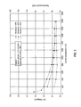
- FIG. 3 depicts a graph of the current density versus the resistance for the fuel cell with various anode utilization.
- the fuel cell has a constant cathode utilization rate, which is about 67%, and the coolant exit temperature is about 80° C.
- the various anode utilization rates illustrate how altering the anode flow rate affects the fuel cell's performance.
- the fuel cell configurations are designated by the symbols, ⁇ , ⁇ , and ⁇ .
- the fuel cell designated by the symbol ⁇ has an anode utilization rate of about 83%.
- the fuel cell designated by the symbol ⁇ has an anode utilization rate of about 67%.
- the fuel cell designated by the symbol ⁇ has an anode utilization rate of about 50%.
- the fuel cell achieves a lower resistance.
- the anode gas flow rate can be increased up to a point where there is no substantial change of the resistance. Once a higher resistance is observed, the anode flow rate can be decreased.
- the anode flow rate is controlled to keep the resistance low to achieve associated uniform hydration of the membrane, so that the durability of the fuel cell is maintained at a high level.
Landscapes
- Life Sciences & Earth Sciences (AREA)
- Engineering & Computer Science (AREA)
- Manufacturing & Machinery (AREA)
- Sustainable Development (AREA)
- Sustainable Energy (AREA)
- Chemical & Material Sciences (AREA)
- Chemical Kinetics & Catalysis (AREA)
- Electrochemistry (AREA)
- General Chemical & Material Sciences (AREA)
- Fuel Cell (AREA)
Abstract
Description
Claims (15)
Priority Applications (2)
| Application Number | Priority Date | Filing Date | Title |
|---|---|---|---|
| US12/801,239 US8932775B2 (en) | 2010-05-28 | 2010-05-28 | Method and apparatus for controlling the operation of a fuel cell |
| PCT/US2011/037516 WO2011149817A1 (en) | 2010-05-28 | 2011-05-23 | Method and apparatus for controlling the operation of a fuel cell |
Applications Claiming Priority (1)
| Application Number | Priority Date | Filing Date | Title |
|---|---|---|---|
| US12/801,239 US8932775B2 (en) | 2010-05-28 | 2010-05-28 | Method and apparatus for controlling the operation of a fuel cell |
Publications (2)
| Publication Number | Publication Date |
|---|---|
| US20110294026A1 US20110294026A1 (en) | 2011-12-01 |
| US8932775B2 true US8932775B2 (en) | 2015-01-13 |
Family
ID=45004303
Family Applications (1)
| Application Number | Title | Priority Date | Filing Date |
|---|---|---|---|
| US12/801,239 Active 2032-05-12 US8932775B2 (en) | 2010-05-28 | 2010-05-28 | Method and apparatus for controlling the operation of a fuel cell |
Country Status (2)
| Country | Link |
|---|---|
| US (1) | US8932775B2 (en) |
| WO (1) | WO2011149817A1 (en) |
Cited By (2)
| Publication number | Priority date | Publication date | Assignee | Title |
|---|---|---|---|---|
| US20180145356A1 (en) * | 2016-11-21 | 2018-05-24 | Toyota Jidosha Kabushiki Kaisha | Fuel cell system |
| US10547072B2 (en) | 2016-10-18 | 2020-01-28 | Toyota Jidosha Kabushiki Kaisha | Fuel cell system |
Families Citing this family (4)
| Publication number | Priority date | Publication date | Assignee | Title |
|---|---|---|---|---|
| US9350033B2 (en) * | 2012-01-10 | 2016-05-24 | Nissan Motor Co., Ltd. | Fuel cell system |
| JP6131930B2 (en) * | 2014-10-28 | 2017-05-24 | トヨタ自動車株式会社 | Power generation monitoring device, fuel cell system, and power generation monitoring method |
| JP2018120281A (en) * | 2017-01-23 | 2018-08-02 | 株式会社Ksf | Hydrogen flow rate control device |
| CN111025157B (en) * | 2019-11-28 | 2022-06-07 | 合肥科威尔电源系统股份有限公司 | Device and method for simulating physical properties of fuel cell stack |
Citations (25)
| Publication number | Priority date | Publication date | Assignee | Title |
|---|---|---|---|---|
| US3471337A (en) | 1967-01-26 | 1969-10-07 | Us Army | Fuel cell rejuvenation control means |
| JPH07235324A (en) | 1994-02-23 | 1995-09-05 | Toyota Motor Corp | Fuel cell drive |
| US5935726A (en) | 1997-12-01 | 1999-08-10 | Ballard Power Systems Inc. | Method and apparatus for distributing water to an ion-exchange membrane in a fuel cell |
| US5998058A (en) | 1998-04-29 | 1999-12-07 | International Fuel Cells Corporation | Porous support layer for an electrochemical cell |
| US5998054A (en) | 1997-07-23 | 1999-12-07 | Plug Power, L.L.C. | Fuel cell membrane hydration and fluid metering |
| US6103412A (en) | 1997-05-13 | 2000-08-15 | Mazda Motor Corporation | Polymer electrolyte fuel cell |
| US6258476B1 (en) | 1999-09-02 | 2001-07-10 | International Fuel Cells, Llc | Porous carbon body with increased wettability by water |
| US6258198B1 (en) | 1997-05-30 | 2001-07-10 | Lintec Corporation | Method and apparatus for applying a protecting film to a semiconductor wafer |
| US6284399B1 (en) | 1999-09-17 | 2001-09-04 | Plug Power Llc | Fuel cell system having humidification membranes |
| US20020009623A1 (en) * | 1999-09-27 | 2002-01-24 | Jean St-Pierre | Methods and apparatus for improving the cold starting capability of a fuel cell |
| US6376111B1 (en) * | 2000-01-25 | 2002-04-23 | General Motors Corporation | System and method for controlling the humidity level of a fuel cell |
| US6376110B1 (en) | 1997-04-10 | 2002-04-23 | Magnet-Motor Gesellschaft Für Magnetmotorische Technik Mbh | Method for regulating membrane moisture of a polymer electrolyte fuel cell, and a polymer electrolyte fuel cell |
| US20020150802A1 (en) * | 2001-04-11 | 2002-10-17 | Tomonori Imamura | Fuel cell system |
| US6709777B2 (en) | 2002-03-20 | 2004-03-23 | Utc Fuel Cells, Llc | Performance recovery process for PEM fuel cells |
| US6841283B2 (en) | 2002-10-21 | 2005-01-11 | Utc Fuel Cells, Llc | High water permeability proton exchange membrane |
| US20050053814A1 (en) * | 2003-09-05 | 2005-03-10 | Denso Corporation | Fuel cell system, related method and current measuring device for fuel cell system |
| US20050147853A1 (en) | 2002-02-01 | 2005-07-07 | Lars Kaufmann | Method of operating a fuel cell with fuel recirculation |
| US20050158610A1 (en) | 2002-03-27 | 2005-07-21 | Delphi Technologies, Inc. | Reversing air flow across a cathode for a fuel cell |
| US20050260463A1 (en) * | 2004-05-21 | 2005-11-24 | Chapman Ivan D | Fluid flow pulsing for increased stability in PEM fuel cell |
| US20060008695A1 (en) | 2004-07-09 | 2006-01-12 | Dingrong Bai | Fuel cell with in-cell humidification |
| US7112379B2 (en) | 2003-05-05 | 2006-09-26 | Utc Fuel Cells, Llc | Vacuum assisted startup of a fuel cell at sub-freezing temperature |
| US7132192B2 (en) | 2001-10-31 | 2006-11-07 | Motorola, Inc. | Fuel cell using variable porosity gas diffusion material |
| JP2007149572A (en) | 2005-11-30 | 2007-06-14 | Denso Corp | Fuel cell system |
| US20070259256A1 (en) * | 2004-11-29 | 2007-11-08 | Jean-Marc Le Canut | Systems and methods for detecting and indicating fault conditions in electrochemical cells |
| US20080138689A1 (en) * | 2006-12-07 | 2008-06-12 | Gm Global Technology Operations, Inc. | System and method for redistribution of the flow of fuel under faulted conditions in a fuel cell system |
-
2010
- 2010-05-28 US US12/801,239 patent/US8932775B2/en active Active
-
2011
- 2011-05-23 WO PCT/US2011/037516 patent/WO2011149817A1/en not_active Ceased
Patent Citations (26)
| Publication number | Priority date | Publication date | Assignee | Title |
|---|---|---|---|---|
| US3471337A (en) | 1967-01-26 | 1969-10-07 | Us Army | Fuel cell rejuvenation control means |
| JPH07235324A (en) | 1994-02-23 | 1995-09-05 | Toyota Motor Corp | Fuel cell drive |
| US6376110B1 (en) | 1997-04-10 | 2002-04-23 | Magnet-Motor Gesellschaft Für Magnetmotorische Technik Mbh | Method for regulating membrane moisture of a polymer electrolyte fuel cell, and a polymer electrolyte fuel cell |
| US6103412A (en) | 1997-05-13 | 2000-08-15 | Mazda Motor Corporation | Polymer electrolyte fuel cell |
| US6258198B1 (en) | 1997-05-30 | 2001-07-10 | Lintec Corporation | Method and apparatus for applying a protecting film to a semiconductor wafer |
| US5998054A (en) | 1997-07-23 | 1999-12-07 | Plug Power, L.L.C. | Fuel cell membrane hydration and fluid metering |
| US5935726A (en) | 1997-12-01 | 1999-08-10 | Ballard Power Systems Inc. | Method and apparatus for distributing water to an ion-exchange membrane in a fuel cell |
| US6753106B2 (en) | 1997-12-01 | 2004-06-22 | Ballard Power Systems Inc. | Method and apparatus for distributing water in an array of fuel cell stacks |
| US5998058A (en) | 1998-04-29 | 1999-12-07 | International Fuel Cells Corporation | Porous support layer for an electrochemical cell |
| US6258476B1 (en) | 1999-09-02 | 2001-07-10 | International Fuel Cells, Llc | Porous carbon body with increased wettability by water |
| US6284399B1 (en) | 1999-09-17 | 2001-09-04 | Plug Power Llc | Fuel cell system having humidification membranes |
| US20020009623A1 (en) * | 1999-09-27 | 2002-01-24 | Jean St-Pierre | Methods and apparatus for improving the cold starting capability of a fuel cell |
| US6376111B1 (en) * | 2000-01-25 | 2002-04-23 | General Motors Corporation | System and method for controlling the humidity level of a fuel cell |
| US20020150802A1 (en) * | 2001-04-11 | 2002-10-17 | Tomonori Imamura | Fuel cell system |
| US7132192B2 (en) | 2001-10-31 | 2006-11-07 | Motorola, Inc. | Fuel cell using variable porosity gas diffusion material |
| US20050147853A1 (en) | 2002-02-01 | 2005-07-07 | Lars Kaufmann | Method of operating a fuel cell with fuel recirculation |
| US6709777B2 (en) | 2002-03-20 | 2004-03-23 | Utc Fuel Cells, Llc | Performance recovery process for PEM fuel cells |
| US20050158610A1 (en) | 2002-03-27 | 2005-07-21 | Delphi Technologies, Inc. | Reversing air flow across a cathode for a fuel cell |
| US6841283B2 (en) | 2002-10-21 | 2005-01-11 | Utc Fuel Cells, Llc | High water permeability proton exchange membrane |
| US7112379B2 (en) | 2003-05-05 | 2006-09-26 | Utc Fuel Cells, Llc | Vacuum assisted startup of a fuel cell at sub-freezing temperature |
| US20050053814A1 (en) * | 2003-09-05 | 2005-03-10 | Denso Corporation | Fuel cell system, related method and current measuring device for fuel cell system |
| US20050260463A1 (en) * | 2004-05-21 | 2005-11-24 | Chapman Ivan D | Fluid flow pulsing for increased stability in PEM fuel cell |
| US20060008695A1 (en) | 2004-07-09 | 2006-01-12 | Dingrong Bai | Fuel cell with in-cell humidification |
| US20070259256A1 (en) * | 2004-11-29 | 2007-11-08 | Jean-Marc Le Canut | Systems and methods for detecting and indicating fault conditions in electrochemical cells |
| JP2007149572A (en) | 2005-11-30 | 2007-06-14 | Denso Corp | Fuel cell system |
| US20080138689A1 (en) * | 2006-12-07 | 2008-06-12 | Gm Global Technology Operations, Inc. | System and method for redistribution of the flow of fuel under faulted conditions in a fuel cell system |
Non-Patent Citations (1)
| Title |
|---|
| International Search Report and the Written Opinion of the International Search Authority, for PCT/US2011-037516, dated May 23, 2011. |
Cited By (3)
| Publication number | Priority date | Publication date | Assignee | Title |
|---|---|---|---|---|
| US10547072B2 (en) | 2016-10-18 | 2020-01-28 | Toyota Jidosha Kabushiki Kaisha | Fuel cell system |
| US20180145356A1 (en) * | 2016-11-21 | 2018-05-24 | Toyota Jidosha Kabushiki Kaisha | Fuel cell system |
| US10804553B2 (en) * | 2016-11-21 | 2020-10-13 | Toyota Jidosha Kabushiki Kaisha | Fuel cell system |
Also Published As
| Publication number | Publication date |
|---|---|
| WO2011149817A1 (en) | 2011-12-01 |
| US20110294026A1 (en) | 2011-12-01 |
Similar Documents
| Publication | Publication Date | Title |
|---|---|---|
| US9281532B2 (en) | Remedial actions for air flow errors in a fuel cell system | |
| US6376111B1 (en) | System and method for controlling the humidity level of a fuel cell | |
| US8932775B2 (en) | Method and apparatus for controlling the operation of a fuel cell | |
| US9099703B2 (en) | Fast MEA break-in and voltage recovery | |
| US10158132B2 (en) | Fuel cell system and method of controlling the fuel cell system | |
| US10553886B2 (en) | Generation of oxygen depleted air by a fuel cell system | |
| US10329150B2 (en) | Fuel cell system and method for determining purity level of hydrogen gas provided to an anode side of the fuel cell | |
| CN102347499A (en) | Diagnosis and remediation of low anode hydrogen partial pressure in pem fuel cell system | |
| CN101262068A (en) | Online detection of stack crossover rate for adaptive hydrogen bleed strategy | |
| KR101588799B1 (en) | Method and apparatus for controlling oxygen pressure of fuel cell system | |
| CN102034995A (en) | Method to improve fuel cell system performance using cell voltage prediction of fuel cell stack | |
| US20100112386A1 (en) | Method for remedial action in the event of the failure of the primary air flow measurement device in a fuel cell system | |
| US8660819B2 (en) | Utilization of HFR-based cathode inlet RH model in comparison to sensor feedback to determine failed water vapor transfer unit and utilize for a diagnostic code and message | |
| CN102237536A (en) | Adaptive method to control fuel delivery injector in a fuel cell system | |
| US8231989B2 (en) | Method for improving FCS reliability after end cell heater failure | |
| US8507141B2 (en) | Membrane permeation adjustment in PEM fuel cell | |
| US20130209906A1 (en) | Reactant control method for a fuel cell system in idle-stop mode | |
| US8071256B2 (en) | Electrochemical energy generating apparatus and method for driving the apparatus | |
| JPWO2010143254A1 (en) | Hydrogen concentration measuring device and fuel cell system | |
| US20160336610A1 (en) | Method for adjusting an operating gas flow in a fuel cell system, and a fuel cell system | |
| US10923749B2 (en) | Method for operating a fuel cell and fuel cell system | |
| CN102195052B (en) | Adaptive method for conversion of external power request to current setpoint to a fuel cell system based on stack performance | |
| US9960438B2 (en) | Fuel cell system and method to prevent water-induced damage | |
| US9105887B2 (en) | Anode injector control algorithm for a low frequency discrete output | |
| KR101817392B1 (en) | Anode-off gas recirculating solid oxide fuel cell system |
Legal Events
| Date | Code | Title | Description |
|---|---|---|---|
| AS | Assignment |
Owner name: UTC POWER CORPORATION, CONNECTICUT Free format text: ASSIGNMENT OF ASSIGNORS INTEREST;ASSIGNORS:DARLING, ROBERT M.;KANDOI, SHAMPA;REEL/FRAME:024512/0992 Effective date: 20100422 Owner name: TOYOTA JIDOSHA KABUSHIKI KAISHA, JAPAN Free format text: ASSIGNMENT OF ASSIGNORS INTEREST;ASSIGNOR:HAMADA, SHIGETAKA;REEL/FRAME:024493/0449 Effective date: 20100527 |
|
| AS | Assignment |
Owner name: TOYOTA JIDOSHA KABUSHIKI KAISHA, JAPAN Free format text: ASSIGNMENT OF ASSIGNORS INTEREST;ASSIGNOR:UTC POWER CORPORATION;REEL/FRAME:026369/0067 Effective date: 20110429 |
|
| STCF | Information on status: patent grant |
Free format text: PATENTED CASE |
|
| FEPP | Fee payment procedure |
Free format text: PAYOR NUMBER ASSIGNED (ORIGINAL EVENT CODE: ASPN); ENTITY STATUS OF PATENT OWNER: LARGE ENTITY |
|
| MAFP | Maintenance fee payment |
Free format text: PAYMENT OF MAINTENANCE FEE, 4TH YEAR, LARGE ENTITY (ORIGINAL EVENT CODE: M1551) Year of fee payment: 4 |
|
| MAFP | Maintenance fee payment |
Free format text: PAYMENT OF MAINTENANCE FEE, 8TH YEAR, LARGE ENTITY (ORIGINAL EVENT CODE: M1552); ENTITY STATUS OF PATENT OWNER: LARGE ENTITY Year of fee payment: 8 |