EP2803437A2 - Drahterodiermaschine mit Rostvermeidungsfunktion - Google Patents
Drahterodiermaschine mit Rostvermeidungsfunktion Download PDFInfo
- Publication number
- EP2803437A2 EP2803437A2 EP14166441.7A EP14166441A EP2803437A2 EP 2803437 A2 EP2803437 A2 EP 2803437A2 EP 14166441 A EP14166441 A EP 14166441A EP 2803437 A2 EP2803437 A2 EP 2803437A2
- Authority
- EP
- European Patent Office
- Prior art keywords
- corrosion preventing
- value
- power supply
- voltage
- processing subject
- Prior art date
- Legal status (The legal status is an assumption and is not a legal conclusion. Google has not performed a legal analysis and makes no representation as to the accuracy of the status listed.)
- Withdrawn
Links
- 230000003405 preventing effect Effects 0.000 title claims abstract description 72
- JEIPFZHSYJVQDO-UHFFFAOYSA-N iron(III) oxide Inorganic materials O=[Fe]O[Fe]=O JEIPFZHSYJVQDO-UHFFFAOYSA-N 0.000 title description 12
- 238000005260 corrosion Methods 0.000 claims abstract description 67
- 230000007797 corrosion Effects 0.000 claims abstract description 67
- 238000000034 method Methods 0.000 claims description 14
- 230000003247 decreasing effect Effects 0.000 claims description 8
- 239000007788 liquid Substances 0.000 claims description 6
- 238000010586 diagram Methods 0.000 description 7
- UFHFLCQGNIYNRP-UHFFFAOYSA-N Hydrogen Chemical compound [H][H] UFHFLCQGNIYNRP-UHFFFAOYSA-N 0.000 description 2
- 230000015556 catabolic process Effects 0.000 description 2
- 238000006731 degradation reaction Methods 0.000 description 2
- 230000006870 function Effects 0.000 description 2
- 229910052739 hydrogen Inorganic materials 0.000 description 2
- 239000001257 hydrogen Substances 0.000 description 2
- 239000000463 material Substances 0.000 description 2
- XLYOFNOQVPJJNP-UHFFFAOYSA-N water Substances O XLYOFNOQVPJJNP-UHFFFAOYSA-N 0.000 description 2
- 230000007423 decrease Effects 0.000 description 1
- 230000004044 response Effects 0.000 description 1
Images


Classifications
-
- B—PERFORMING OPERATIONS; TRANSPORTING
- B23—MACHINE TOOLS; METAL-WORKING NOT OTHERWISE PROVIDED FOR
- B23H—WORKING OF METAL BY THE ACTION OF A HIGH CONCENTRATION OF ELECTRIC CURRENT ON A WORKPIECE USING AN ELECTRODE WHICH TAKES THE PLACE OF A TOOL; SUCH WORKING COMBINED WITH OTHER FORMS OF WORKING OF METAL
- B23H7/00—Processes or apparatus applicable to both electrical discharge machining and electrochemical machining
- B23H7/02—Wire-cutting
- B23H7/04—Apparatus for supplying current to working gap; Electric circuits specially adapted therefor
-
- B—PERFORMING OPERATIONS; TRANSPORTING
- B23—MACHINE TOOLS; METAL-WORKING NOT OTHERWISE PROVIDED FOR
- B23H—WORKING OF METAL BY THE ACTION OF A HIGH CONCENTRATION OF ELECTRIC CURRENT ON A WORKPIECE USING AN ELECTRODE WHICH TAKES THE PLACE OF A TOOL; SUCH WORKING COMBINED WITH OTHER FORMS OF WORKING OF METAL
- B23H1/00—Electrical discharge machining, i.e. removing metal with a series of rapidly recurring electrical discharges between an electrode and a workpiece in the presence of a fluid dielectric
- B23H1/02—Electric circuits specially adapted therefor, e.g. power supply, control, preventing short circuits or other abnormal discharges
-
- B—PERFORMING OPERATIONS; TRANSPORTING
- B23—MACHINE TOOLS; METAL-WORKING NOT OTHERWISE PROVIDED FOR
- B23H—WORKING OF METAL BY THE ACTION OF A HIGH CONCENTRATION OF ELECTRIC CURRENT ON A WORKPIECE USING AN ELECTRODE WHICH TAKES THE PLACE OF A TOOL; SUCH WORKING COMBINED WITH OTHER FORMS OF WORKING OF METAL
- B23H7/00—Processes or apparatus applicable to both electrical discharge machining and electrochemical machining
- B23H7/38—Influencing metal working by using specially adapted means not directly involved in the removal of metal, e.g. ultrasonic waves, magnetic fields or laser irradiation
Definitions
- the present invention relates to a wire electric discharge processing machine that prevents rust of a processing subject.
- a corrosion preventing electrode is provided so as to face a processing subject through a processing liquid and a voltage is applied from an external power supply to the processing subject and the corrosion preventing electrode so as to prevent the rust of the processing subject while using the processing subject as a negative pole and using the corrosion preventing electrode as a positive pole .
- the current density is a value that is obtained by dividing a current value of a current supplied from a rust preventing power supply by a physical quantity concerning the surface area of the processing subject.
- an object of the present invention is to provide a wire electric discharge processing machine with a rust preventing function that changes a value of a voltage applied between a processing subject and a corrosion preventing electrode and controls a current density with respect to the processing subject at a constant value.
- an electric discharge processing machine with a corrosion preventing power supply unit in which a processing subject and a tool electrode are made to face each other through a processing liquid, a voltage is applied to the processing subject and the tool electrode so as to process the processing subject, and a voltage is applied to the processing subject and a corrosion preventing electrode provided inside the processing liquid
- the electric discharge processing machine including: a corrosion preventing power supply voltage value changing unit that changes the application voltage of the corrosion preventing power supply unit so that the density of the current flowing to the processing subject is constantly maintained.
- the electric discharge processing machine may include a current detector that detects a current flowing from the corrosion preventing power supply unit to the processing subject; and the corrosion preventing power supply voltage value changing unit that compares the current with a reference current value according to the surface area of the processing subject and constantly maintains the current density by decreasing the application voltage when the current is larger than the reference current value and increasing the application voltage when the current is smaller than the reference current value.
- the electric discharge processing machine may include an alarm display unit that displays an alarm when the value of the current density does not fall within a predetermined range.
- the wire electric discharge processing machine with the rust preventing function that changes the value of the voltage applied between the processing subject and the corrosion preventing electrode and controls the current density with respect to the processing subject at a constant value.
- the current density indicates a value that is obtained by dividing the current value of the current supplied from the corrosion preventing power supply by the physical quantity concerning with the surface area of the processing subject.
- a sufficient corrosion preventing effect is not achieved when the current density of the processing subject is smaller than a predetermined value.
- the lifetime of the corrosion preventing electrode is shortened or the processing subject is degraded due to the generation of hydrogen when the current density is too large.
- a sufficient corrosion preventing effect or a sufficient rust preventing effect may not be achieved according to the size, that is, the surface area of the processing subject.
- FIG. 1 illustrates a relation between the reference current value and the surface area of the processing subject.
- Is indicates a relation between the reference current value and the surface area of the processing subject in a case where the current density is constantly maintained at a predetermined value
- Is1 indicates a relation therebetween in a case where the current density is slightly smaller than a predetermined value
- Is2 indicates a relation therebetween in a case where the current density is slightly larger than a predetermined value.
- the corrosion preventing current is controlled at a value between Is1 and Is2. Furthermore, a plurality of graphs of relations between the reference current value and the surface area of the processing subject may be prepared corresponding to different materials of the processing subjects, and may be stored in a memory of the control device of the wire electric discharge processing machine.
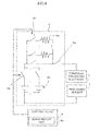
- an wire electric discharge processing machine in which a processing power supply 3 is connected between a wire electrode 2 and a processing subject 1 placed on a table 9 includes a voltage variable corrosion preventing power supply 6 that disposes a corrosion preventing electrode 5 inside a processing tank 4 so as to face the processing subject 1 and applies a voltage between the processing subject 1 and the corrosion preventing electrode 5 so that the processing subject 1 becomes a negative pole and the corrosion preventing electrode 5 becomes a positive pole, a current detector 7 that detects a value of a current 10 flowing between the processing subject 1 and the corrosion preventing electrode 5, and a control device 8 that transmits an instruction of changing the voltage value of the corrosion preventing power supply 6 so that the detected current value becomes the current according to the surface area of the processing subject 1.
- the current detector 7 detects the current 10 flowing between the processing subject 1 and the corrosion preventing electrode 5. Then, when the voltage value of the corrosion preventing power supply is controlled so that the detected current becomes the current value according to the surface area of the processing subject 1, the current density becomes a predetermined value. Furthermore, the control device 8 includes an alarm display unit 8a that displays an alarm in a case where the current density may not be controlled at a constant value.
- the switch 6b illustrated in FIG. 3 is a switch that interrupts the application of the voltage from the corrosion preventing power supply 6 between the corrosion preventing electrode 5 and the processing subject 1.
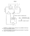
- a switch 6g illustrated in FIG. 4 is a switch that interrupts the application of the voltage from the corrosion preventing power supply 6 between the corrosion preventing electrode 5 and the processing subject 1.
- the electric discharge processing machine has a configuration in which a current detecting resistor is provided between the processing subject and the corrosion preventing power supply which includs the variable DC power supply capable of changing the voltage value by the external signal, so as to detect a current value based on the voltages of both ends of the resistor, and the control device compares the detected current value with the reference current value according to the surface area of the processing subject illustrated in FIG. 1 . Then, the control device outputs a signal to the variable DC power supply so that the voltage value of the variable DC power supply increases when the detected current is smaller than the reference current value or the voltage value of the variable DC power supply decreases when the detected current is larger than the reference current value, thereby constantly maintaining the current density of the processing subject.
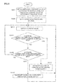
- FIG. 6 illustrates a flowchart.
- the lower-limit value and the upper-limit value of the reference current value are set so as to fall within a certain range.
- the current density may be constantly maintained, and hence the rust of the processing subject may be stably prevented.
- the reference current value may be changed according to the materials of the processing subjects.
- a control may be performed in which the voltage is gradually increased or decreased by a predetermined voltage range.
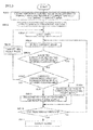
- FIG. 7 illustrates a flow including an alarm process step in the control flow illustrated in FIG. 6 .
- the degradation of the corrosion preventing electrode or the disconnection of the cable is considered to be the reason for the smaller current value.
- the current value is larger than the reference value, the short-circuiting between the processing subject and the corrosion preventing electrode is considered to be the reason for the larger current value.
- an alarm is displayed when the value of the current density does not fall within a predetermined range, and hence the degradation of the corrosion preventing electrode or the problem of the corrosion preventing power supply unit may be notified.
- this process will be described according to the steps.
- a control may be performed in which the voltage is gradually increased or decreased by a predetermined voltage range.
Landscapes
- Engineering & Computer Science (AREA)
- Mechanical Engineering (AREA)
- Chemical & Material Sciences (AREA)
- Chemical Kinetics & Catalysis (AREA)
- Electrochemistry (AREA)
- Electrical Discharge Machining, Electrochemical Machining, And Combined Machining (AREA)
- Prevention Of Electric Corrosion (AREA)
Applications Claiming Priority (1)
| Application Number | Priority Date | Filing Date | Title |
|---|---|---|---|
| JP2013105225A JP5689499B2 (ja) | 2013-05-17 | 2013-05-17 | 防錆機能を有するワイヤ放電加工機 |
Publications (2)
| Publication Number | Publication Date |
|---|---|
| EP2803437A2 true EP2803437A2 (de) | 2014-11-19 |
| EP2803437A3 EP2803437A3 (de) | 2015-01-14 |
Family
ID=50771403
Family Applications (1)
| Application Number | Title | Priority Date | Filing Date |
|---|---|---|---|
| EP14166441.7A Withdrawn EP2803437A3 (de) | 2013-05-17 | 2014-04-29 | Drahterodiermaschine mit Rostvermeidungsfunktion |
Country Status (4)
| Country | Link |
|---|---|
| US (1) | US20140339199A1 (de) |
| EP (1) | EP2803437A3 (de) |
| JP (1) | JP5689499B2 (de) |
| CN (1) | CN104162723B (de) |
Citations (2)
| Publication number | Priority date | Publication date | Assignee | Title |
|---|---|---|---|---|
| JPH05220618A (ja) | 1992-02-07 | 1993-08-31 | Mitsubishi Electric Corp | 放電加工装置 |
| JP2004291206A (ja) | 2003-03-28 | 2004-10-21 | Fanuc Ltd | 放電加工機 |
Family Cites Families (27)
| Publication number | Priority date | Publication date | Assignee | Title |
|---|---|---|---|---|
| US3816692A (en) * | 1972-03-02 | 1974-06-11 | S Ratmansky | Electrical discharge machining efficiency and safety monitoring system |
| US3777102A (en) * | 1972-07-19 | 1973-12-04 | Colt Ind Operating Corp | Electrical discharge machining power supply circuit |
| US4004123A (en) * | 1973-02-20 | 1977-01-18 | Inoue K | Method of and system for the controlling of an apparatus for the electric discharge machining of a workpiece |
| JPS60201826A (ja) * | 1984-03-26 | 1985-10-12 | Fanuc Ltd | ワイヤ放電加工電源 |
| JPH0818184B2 (ja) * | 1986-09-09 | 1996-02-28 | ブラザー工業株式会社 | 放電加工機 |
| JPH051392A (ja) * | 1991-04-18 | 1993-01-08 | Tdk Corp | 希土類合金の保存方法、希土類合金の製造方法、希土類合金の使用方法および防錆手段を有する希土類合金 |
| JP2954774B2 (ja) * | 1992-01-28 | 1999-09-27 | 三菱電機株式会社 | 放電加工機用電源装置 |
| US5276302A (en) * | 1992-05-18 | 1994-01-04 | Mitsubishi Denki K.K. | EDM apparatus current efficiency control technique |
| JP3057953B2 (ja) * | 1993-02-25 | 2000-07-04 | 株式会社ソディック | ワイヤカット放電加工装置 |
| JP2914102B2 (ja) * | 1993-06-30 | 1999-06-28 | 三菱電機株式会社 | 放電加工機 |
| JP3057033B2 (ja) * | 1997-07-10 | 2000-06-26 | 木村化工機株式会社 | ステンレス鋼防食表面処理方法 |
| DE10085332B4 (de) * | 2000-10-20 | 2006-09-07 | Mitsubishi Denki K.K. | Vorrichtung zur Bearbeitung mittels elektronischer Entladung mit einer Energieversorgungseinrichtung |
| JP2004244575A (ja) * | 2003-02-17 | 2004-09-02 | Thk Co Ltd | クーラントおよびそれを使用する機械加工装置 |
| WO2007113906A1 (ja) * | 2006-04-05 | 2007-10-11 | Mitsubishi Denki Kabushiki Kaisha | 放電加工装置及び放電加工方法 |
| JP2009039817A (ja) * | 2007-08-09 | 2009-02-26 | Sodick Co Ltd | 放電加工装置 |
| CN101144166A (zh) * | 2007-09-21 | 2008-03-19 | 大庆石油管理局 | 为实现充海水试压对大型储油罐进行防腐蚀处理的方法 |
| WO2009096026A1 (ja) * | 2008-01-31 | 2009-08-06 | Mitsubishi Electric Corporation | 放電加工装置 |
| JP4849568B2 (ja) * | 2008-10-29 | 2012-01-11 | 株式会社ソディック | 放電加工装置におけるワークの防食方法および放電加工装置 |
| GB2471073A (en) * | 2009-06-15 | 2010-12-22 | Gareth Kevin Glass | Corrosion Protection of Steel in Concrete |
| JP5588634B2 (ja) * | 2009-07-09 | 2014-09-10 | 西部電機株式会社 | ワイヤ放電加工装置及びその方法 |
| DE102009036221A1 (de) * | 2009-08-05 | 2011-02-17 | Extrude Hone Gmbh | Verfahren zur elektrochemischen Bearbeitung eines Werkstückes |
| JP4902721B2 (ja) * | 2009-10-23 | 2012-03-21 | キヤノン株式会社 | 光断層画像生成装置及び光断層画像生成方法 |
| WO2011084937A2 (en) * | 2010-01-05 | 2011-07-14 | A123 Systems, Inc. | System and method for controlling voltage of individual battery cells within a battery pack |
| JP2012091289A (ja) * | 2010-10-27 | 2012-05-17 | Makino Milling Mach Co Ltd | 放電加工機 |
| TWI413559B (zh) * | 2010-12-17 | 2013-11-01 | Ind Tech Res Inst | 自調式放電加工節能電源裝置及其方法 |
| DE112011104971B4 (de) * | 2011-04-12 | 2022-05-25 | Mitsubishi Electric Corporation | Stromversorgungsvorrichtung für elektroerosionsapparat undelektroerosionsverfahren |
| JP6118816B2 (ja) * | 2012-11-16 | 2017-04-19 | 日立オートモティブシステムズ株式会社 | 接合部材、単電池および組電池 |
-
2013
- 2013-05-17 JP JP2013105225A patent/JP5689499B2/ja not_active Expired - Fee Related
-
2014
- 2014-04-29 EP EP14166441.7A patent/EP2803437A3/de not_active Withdrawn
- 2014-05-02 US US14/267,915 patent/US20140339199A1/en not_active Abandoned
- 2014-05-19 CN CN201410211011.4A patent/CN104162723B/zh not_active Expired - Fee Related
Patent Citations (2)
| Publication number | Priority date | Publication date | Assignee | Title |
|---|---|---|---|---|
| JPH05220618A (ja) | 1992-02-07 | 1993-08-31 | Mitsubishi Electric Corp | 放電加工装置 |
| JP2004291206A (ja) | 2003-03-28 | 2004-10-21 | Fanuc Ltd | 放電加工機 |
Also Published As
| Publication number | Publication date |
|---|---|
| JP5689499B2 (ja) | 2015-03-25 |
| US20140339199A1 (en) | 2014-11-20 |
| CN104162723B (zh) | 2016-06-22 |
| CN104162723A (zh) | 2014-11-26 |
| EP2803437A3 (de) | 2015-01-14 |
| JP2014223712A (ja) | 2014-12-04 |
Similar Documents
| Publication | Publication Date | Title |
|---|---|---|
| CN110515002B (zh) | 电池容量监测器 | |
| JP6325497B2 (ja) | バッテリー残量を報知する機能を有する電子機器 | |
| CN102407391A (zh) | 具有自动切换恒温控制和温差控制的功能的电火花线切割加工机 | |
| CN109514015B (zh) | 加工液处理装置以及加工液处理装置的控制方法 | |
| EP2985105B1 (de) | Drahterosionsmaschine mit funktion zur bestimmung, ob eine drahterosion eines werkstücks durchgeführt werden kann oder nicht | |
| JP2018034270A (ja) | ワイヤ放電加工機 | |
| CN103240469B (zh) | 具有加工液的温度控制功能的线放电加工机 | |
| US9533365B2 (en) | Electric discharge machining apparatus | |
| EP2803437A2 (de) | Drahterodiermaschine mit Rostvermeidungsfunktion | |
| US10913124B2 (en) | Power supply control apparatus of electric discharge machine | |
| JP2005312224A (ja) | バッテリ充電装置 | |
| EP2693180B1 (de) | Temperaturwächter einer elektrischen Drahterodiermaschine | |
| JP7302334B2 (ja) | 制御モジュール、測定装置、及び制御方法 | |
| EP3189919B1 (de) | Verfahren zur verschleisserkennung des pulsstromkabels einer drahterodiermaschine | |
| KR102447061B1 (ko) | 와이어 방전 가공기 및 방전 가공 방법 | |
| CN106493441B (zh) | 放电加工机 | |
| JP2018050395A (ja) | インバータ装置 | |
| JP2001086658A (ja) | 電池活性化装置 | |
| JPH04304925A (ja) | ジャンプ加工時の放電加工を安定化する放電加工方法 | |
| CN111755310A (zh) | 等离子处理装置 | |
| DE102011109749A1 (de) | Verfahren und Vorrichtung zum Betreiben eines Ultraschallgeräts |
Legal Events
| Date | Code | Title | Description |
|---|---|---|---|
| PUAI | Public reference made under article 153(3) epc to a published international application that has entered the european phase |
Free format text: ORIGINAL CODE: 0009012 |
|
| 17P | Request for examination filed |
Effective date: 20140429 |
|
| AK | Designated contracting states |
Kind code of ref document: A2 Designated state(s): AL AT BE BG CH CY CZ DE DK EE ES FI FR GB GR HR HU IE IS IT LI LT LU LV MC MK MT NL NO PL PT RO RS SE SI SK SM TR |
|
| AX | Request for extension of the european patent |
Extension state: BA ME |
|
| PUAL | Search report despatched |
Free format text: ORIGINAL CODE: 0009013 |
|
| AK | Designated contracting states |
Kind code of ref document: A3 Designated state(s): AL AT BE BG CH CY CZ DE DK EE ES FI FR GB GR HR HU IE IS IT LI LT LU LV MC MK MT NL NO PL PT RO RS SE SI SK SM TR |
|
| AX | Request for extension of the european patent |
Extension state: BA ME |
|
| RIC1 | Information provided on ipc code assigned before grant |
Ipc: B23H 7/38 20060101ALN20141208BHEP Ipc: B23H 1/02 20060101ALN20141208BHEP Ipc: B23H 7/04 20060101AFI20141208BHEP |
|
| R17P | Request for examination filed (corrected) |
Effective date: 20150710 |
|
| RBV | Designated contracting states (corrected) |
Designated state(s): AL AT BE BG CH CY CZ DE DK EE ES FI FR GB GR HR HU IE IS IT LI LT LU LV MC MK MT NL NO PL PT RO RS SE SI SK SM TR |
|
| 17Q | First examination report despatched |
Effective date: 20161117 |
|
| STAA | Information on the status of an ep patent application or granted ep patent |
Free format text: STATUS: THE APPLICATION IS DEEMED TO BE WITHDRAWN |
|
| 18D | Application deemed to be withdrawn |
Effective date: 20171209 |