EP2802750B1 - Schalldämpfer-anordnung - Google Patents
Schalldämpfer-anordnung Download PDFInfo
- Publication number
- EP2802750B1 EP2802750B1 EP13700155.8A EP13700155A EP2802750B1 EP 2802750 B1 EP2802750 B1 EP 2802750B1 EP 13700155 A EP13700155 A EP 13700155A EP 2802750 B1 EP2802750 B1 EP 2802750B1
- Authority
- EP
- European Patent Office
- Prior art keywords
- control device
- exhaust gas
- signals
- arrangement according
- engine speed
- Prior art date
- Legal status (The legal status is an assumption and is not a legal conclusion. Google has not performed a legal analysis and makes no representation as to the accuracy of the status listed.)
- Active
Links
- 230000003584 silencer Effects 0.000 claims description 20
- 238000002485 combustion reaction Methods 0.000 claims description 11
- 230000003213 activating effect Effects 0.000 claims description 4
- 230000003111 delayed effect Effects 0.000 claims 1
- 230000001133 acceleration Effects 0.000 description 19
- 230000005540 biological transmission Effects 0.000 description 19
- 238000012360 testing method Methods 0.000 description 19
- 239000000463 material Substances 0.000 description 7
- 238000010521 absorption reaction Methods 0.000 description 6
- 238000005259 measurement Methods 0.000 description 6
- 238000004891 communication Methods 0.000 description 4
- 230000001419 dependent effect Effects 0.000 description 4
- 238000001514 detection method Methods 0.000 description 3
- 230000002238 attenuated effect Effects 0.000 description 2
- 239000003054 catalyst Substances 0.000 description 2
- 229920002748 Basalt fiber Polymers 0.000 description 1
- 229910000831 Steel Inorganic materials 0.000 description 1
- 230000002745 absorbent Effects 0.000 description 1
- 239000002250 absorbent Substances 0.000 description 1
- 230000006978 adaptation Effects 0.000 description 1
- 238000009530 blood pressure measurement Methods 0.000 description 1
- 238000013461 design Methods 0.000 description 1
- 230000000694 effects Effects 0.000 description 1
- 239000011152 fibreglass Substances 0.000 description 1
- 238000012423 maintenance Methods 0.000 description 1
- 238000012545 processing Methods 0.000 description 1
- 229910001220 stainless steel Inorganic materials 0.000 description 1
- 239000010935 stainless steel Substances 0.000 description 1
- 239000010959 steel Substances 0.000 description 1
- 210000002268 wool Anatomy 0.000 description 1
Images

Classifications
-
- F—MECHANICAL ENGINEERING; LIGHTING; HEATING; WEAPONS; BLASTING
- F01—MACHINES OR ENGINES IN GENERAL; ENGINE PLANTS IN GENERAL; STEAM ENGINES
- F01N—GAS-FLOW SILENCERS OR EXHAUST APPARATUS FOR MACHINES OR ENGINES IN GENERAL; GAS-FLOW SILENCERS OR EXHAUST APPARATUS FOR INTERNAL COMBUSTION ENGINES
- F01N1/00—Silencing apparatus characterised by method of silencing
- F01N1/16—Silencing apparatus characterised by method of silencing by using movable parts
- F01N1/166—Silencing apparatus characterised by method of silencing by using movable parts for changing gas flow path through the silencer or for adjusting the dimensions of a chamber or a pipe
-
- F—MECHANICAL ENGINEERING; LIGHTING; HEATING; WEAPONS; BLASTING
- F01—MACHINES OR ENGINES IN GENERAL; ENGINE PLANTS IN GENERAL; STEAM ENGINES
- F01N—GAS-FLOW SILENCERS OR EXHAUST APPARATUS FOR MACHINES OR ENGINES IN GENERAL; GAS-FLOW SILENCERS OR EXHAUST APPARATUS FOR INTERNAL COMBUSTION ENGINES
- F01N9/00—Electrical control of exhaust gas treating apparatus
-
- F—MECHANICAL ENGINEERING; LIGHTING; HEATING; WEAPONS; BLASTING
- F01—MACHINES OR ENGINES IN GENERAL; ENGINE PLANTS IN GENERAL; STEAM ENGINES
- F01N—GAS-FLOW SILENCERS OR EXHAUST APPARATUS FOR MACHINES OR ENGINES IN GENERAL; GAS-FLOW SILENCERS OR EXHAUST APPARATUS FOR INTERNAL COMBUSTION ENGINES
- F01N2900/00—Details of electrical control or of the monitoring of the exhaust gas treating apparatus
- F01N2900/06—Parameters used for exhaust control or diagnosing
- F01N2900/08—Parameters used for exhaust control or diagnosing said parameters being related to the engine
-
- Y—GENERAL TAGGING OF NEW TECHNOLOGICAL DEVELOPMENTS; GENERAL TAGGING OF CROSS-SECTIONAL TECHNOLOGIES SPANNING OVER SEVERAL SECTIONS OF THE IPC; TECHNICAL SUBJECTS COVERED BY FORMER USPC CROSS-REFERENCE ART COLLECTIONS [XRACs] AND DIGESTS
- Y02—TECHNOLOGIES OR APPLICATIONS FOR MITIGATION OR ADAPTATION AGAINST CLIMATE CHANGE
- Y02T—CLIMATE CHANGE MITIGATION TECHNOLOGIES RELATED TO TRANSPORTATION
- Y02T10/00—Road transport of goods or passengers
- Y02T10/10—Internal combustion engine [ICE] based vehicles
- Y02T10/40—Engine management systems
Definitions
- the invention relates to a muffler arrangement for exhaust systems with internal combustion engine.
- the internal combustion engine is preferably a diesel or gasoline engine.
- Exhaust systems of motor vehicles must comply with legally prescribed noise emission limits.
- a maximum volume of the exhaust system is desired by motorcyclists when driving in general.
- the legally prescribed noise emission limits are not uniformly set worldwide, so that a complex adaptation to the respectively locally prevailing noise emission limit values is often required for exporting exhaust systems.
- the invention is based on the object, a silencer assembly to provide an extremely accurate and easy adjustment of the volume of the muffler. Furthermore, the muffler assembly should have a high reliability.
- the core of the invention is that the control device receives vehicle speed signals and engine speed signals of the motor vehicle, wherein the at least one adjustment drive in response to the vehicle speed signals and the engine speed signals and from the vehicle speed signals and / or the Engine speed signals calculated gear signals for adjusting the at least one adjustment body is actuated.
- Vehicle speed signals are here understood as signals which are representative of the current driving speed of the motor vehicle.
- the signals are preferably electrical or electronic.
- the control device is an electronic control device.
- a vehicle speed sensor senses the current driving speed of the motor vehicle.
- the control device fetches the vehicle speed signals from an electronic control unit of the motor vehicle.
- an engine speed sensor senses the current engine speed of the motor vehicle.
- the control device fetches the engine speed signals from the control electronics of the motor vehicle.
- the engine speed signals may alternatively be determinable by the ignition pulses of the internal combustion engine.
- the invention leads to a muffler arrangement whose volume is extremely accurate and easily adjustable.
- Transmission gear signals are here understood to be signals which are representative of the respectively selected transmission gear of the motor vehicle.
- the muffler arrangement is extremely simple.
- the transmission gear signals are calculated here by the control device. A measurement of the transmission gear signals is therefore not.
- the flow of the exhaust gas in the exhaust gas flow pipe can be influenced.
- the at least one adjusting body may allow or completely prevent a flow of the exhaust gas in the exhaust gas flow pipe.
- the at least one adjusting body can also influence the flow velocity of the exhaust gas in the exhaust gas flow pipe.
- the noise emission of the muffler is changeable.
- the at least one adjusting body for example, the exhaust gas flow and the exhaust gas back pressure can be changed, which also has an effect on the power and the torque of the internal combustion engine of the motor vehicle.
- the at least one adjustment body is infinitely adjustable.
- the at least one adjusting body is arranged in the exhaust gas flow pipe. It may be located on the input side or on the output side in the exhaust gas flow pipe. However, it can also be arranged in an area which, preferably approximately in the middle, lies between the exhaust gas inlet opening and the exhaust gas outlet opening. However, the at least one adjusting body can also be arranged on or adjacent to the exhaust gas flow pipe.
- the at least one adjusting body is designed as an adjusting flap, which is pivotable between an opening position and a closing position.
- the pivoting movement of the at least one adjusting flap is preferably localized.
- appropriate end stops can be used which prevent further pivoting of the at least one adjusting body.
- the at least one adjusting body is mounted pivotably.
- the at least one adjusting drive is an electric actuating drive or a servo drive or another direct current drive.
- connection between the adjusting drive and the adjusting body is preferably via a flexible shaft, a flexible or rigid Bowden cable, a worm gear, bevel gears, conventional gears, toothed connections, a V-belt, a chain drive, a propshaft , Lever ratios, a lever ball lever deflection, a linkage, a thread or a threaded rod.
- the motor vehicles include, for example, motorcycles, passenger cars, trucks, buses, tractors and special motor vehicles counted.
- the muffler is preferably an end or center muffler.
- the exhaust gas flow pipe is preferably annular in cross section. But it can also have any other cross-sections, such as an oval cross-section. It is preferably at least partially perforated circumferentially and connectable to an internal combustion engine.
- the internal combustion engine may be associated with a catalyst for exhaust aftertreatment.
- the internal combustion engine can also be assigned no catalyst.
- the exhaust gas flow pipe is at least partially surrounded by an absorption material.
- an absorption material for example, steel or stainless steel wool, basalt fibers, fiberglass mats or threads or the like can be used as the absorption material.
- the absorption material is at least partially surrounded by a silencer housing.
- the muffler housing may be circular or oval in cross-section. However, it can also have other cross-sectional shapes.
- the muffler assembly may also include more than one muffler.
- the silencers are then connected in series or in parallel.
- the embodiment according to claim 2 leads to a muffler arrangement whose volume is extremely accurate and easy to control.
- the control device according to claim 4 or 5 is extremely versatile. Under motor vehicle-independent signals are understood here, for example, radar warning signals or Fahrzyklensignale.
- Threshold values and / or other values can preferably be fed to the control device via the input input.
- control device actuates the adjusting drive for adjusting the at least one adjusting body when the at least one speed threshold value according to claim 6 is exceeded or undershot.
- at least one vehicle speed interval is stored in the control device, which is limited by at least one vehicle speed threshold.
- control device actuates the adjusting drive for adjusting the at least one adjusting body when the at least one engine speed threshold value is exceeded or undershot.
- at least one engine speed interval is stored in the control device, which is limited by at least one engine speed threshold.
- control device actuates the adjusting drive for adjusting the at least one adjusting body when the at least one transmission gear threshold value is exceeded or undershot.
- at least one transmission gear interval is stored in the control device, which is limited by at least one transmission gear threshold value.
- control device is remote-controlled. For example, this is so switched on or off. It is useful if thresholds are variable by the remote control.
- the embodiment of claim 10 provides a muffler assembly that is extremely comfortable.
- a muffler assembly includes a muffler 1 having an exhaust flow pipe 2 and an adjusting body 3 arranged downstream of the exhaust gas flow pipe 2 for influencing the flow of the exhaust gas in the exhaust gas flow pipe 2.
- the muffler 1 further has an adjusting drive 4, which is in drive connection with the adjusting body 3 for adjusting the same.
- the muffler assembly further comprises a control device 5, which is in communication with the adjustment drive 4 for actuating the same in a data-transmitting manner.
- the exhaust flow pipe 2 defines an exhaust flow channel. It is preferably laterally surrounded by absorbent material 6. Furthermore, the silencer 1 has a silencer housing 7 which surrounds the absorption material 6 on the outside and is preferably annular in cross section.
- the silencer 1 has on the input side a connection piece 8 which can be connected to an internal combustion engine of a motor vehicle or to another silencer.
- an adjusting body receptacle 9 Downstream of the absorption material 6 and the exhaust gas flow pipe 2, an adjusting body receptacle 9 is arranged in the muffler housing 7, which is annular in cross section.
- the adjusting body receptacle 9 defines an exhaust gas passage channel 10, in which the adjusting body 3 is accommodated in an actuatable manner.
- the adjusting body 3 is formed by a circular flap whose diameter corresponds approximately to the inner diameter of the adjusting body receptacle 9. He stands with a bearing body in a rotationally fixed connection, in the Adjusting body receptacle 9 is pivotally mounted and can be pivoted by applying an external pivoting force.
- the bearing body is preferably pin-shaped and extends perpendicular to a longitudinal center axis 11 of the muffler first
- the adjusting drive 4 is preferably an electric actuating drive or a servo drive or another direct current drive. He preferably has a drive shaft (not shown), which is in operative connection with the adjusting body 3 for actuating the same. Furthermore, the adjusting drive 4 comprises an end stop 12, which is preferably fixedly attached to the housing of the adjusting drive 4. It can interact with a driver (not shown) attached to the drive shaft. When the driver comes to rest on the end stop 12, the current of the adjustment drive 4 increases. This is then detected by the control device 5. Alternatively, however, an actuating time can also be programmed for the adjusting drive 4 in which it then runs in one direction. Such a design is technically extremely simple and inexpensive to implement. The mechanical stop is nevertheless advantageous for mechanical reasons.
- the bypass body may be an internal or external bypass body. If the bypass body is formed as an internal bypass body, it extends within the muffler housing 7 and preferably along the exhaust flow pipe 2. If the bypass body is designed as an external bypass body, this is with the Exhaust flow pipe 2 in flow communication and extends substantially outside the muffler housing 7. Other configurations are alternatively possible.
- the exhaust gas passage channel 10 is released.
- the adjusting body 3 is pivoted here about its closed position by about 90 °.
- the pivoting movement is effected by the adjusting drive 4.
- the exhaust gas can thus flow through the exhaust gas flow pipe 2 completely axially and thereby also pass through the exhaust gas passage channel 11.
- the sound is attenuated more strongly when the adjusting body 3 is closed than when the adjusting body 3 is open.
- the muffler 1 is thus quieter when the adjusting body 3 is closed than when the adjusting body 3 is open.
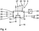
- control device 5 The actuation or control of the adjustment drive 4 is performed by the control device 5, which will now be discussed in more detail below.
- the control device 5 has a vehicle speed signal input 13, which communicates with a vehicle speed sensor 14 in a data-transmitting manner.
- the vehicle speed sensor 14 senses the current driving speed of the motor vehicle. For the driving speed of the motor vehicle, representative driving speed signals are then supplied to the control device 5 via the vehicle speed signal input 13 during operation of the motor vehicle.
- the controller 5 further has an engine speed signal input 15 which communicates with an engine speed sensor 16 in a data transmitting manner.
- the engine speed sensor 16 senses the current engine speed of the internal combustion engine of the motor vehicle. For the engine speed representative engine speed signals 15 are then supplied to the control device 5 during operation of the motor vehicle via the engine speed signal input 15.
- the control device 5 also has an exhaust gas backpressure signal input 17 which is connected to an exhaust gas back pressure sensor 18 in a data-transmitting manner Connection stands.
- the exhaust gas backpressure sensor 18 senses the exhaust gas counterpressure currently prevailing in the exhaust gas flow pipe 2. For the exhaust back pressure representative exhaust back pressure signals are then supplied via the exhaust back pressure signal input 17 of the control device 5.
- the control device 5 also has an input 19 for vehicle-independent signals.
- the input 19 is in communication with a detection unit 20 in a data transmitting manner.
- the determination or detection unit 20 detects or detects motor vehicle-independent signals, such as radar warning signals, driving cycles or the like. These signals are supplied via the input 19 of the control device 5.
- the control device 5 also has an input input 21. Via the input input 21, the control device 5 can be supplied with various values, such as threshold values and / or motor vehicle values, such as weight, length or the like. With the input-input 21, a corresponding input unit 22 is connected, which is preferably a computer, a keyboard or the like.
- a push-button switch 23 is connected to the control device 5, which is used for manual switching on and off of the speed-dependent and / or speed-dependent and / or transmission-dependent automatic control device 5.
- the touch switch 23 is used only for activating / switching on or off / off the speed, speed and / or transmission-dependent automatic control 5. When "deactivating" the adjusting body 3 remains in its closed position.
- an exhaust test button 24 is in communication with the controller 5. This is used to completely switch off the control device 5. With the exhaust test button 24 is a test mode in the control device 5 can be activated, which makes the control of the adjustment body 3 without having to drive. By pressing the exhaust test button 24, the Functionality of the muffler 1 after attachment to the vehicle or to be checked for maintenance.
- control device 5 has a remote control 25 via which it can be operated remotely.
- control device 5 is connected to the adjustment drive 4 in data transmission manner for actuating the same.
- the control device 5 also comprises a central unit 27 which, according to the invention, calculates the corresponding transmission gears in each case during operation of the control device 5 from the received vehicle speed signals and engine speed signals.
- the controller 5 receives vehicle speed signals and engine speed signals.
- the central unit 27 calculates the transmission gears of the motor vehicle by means of the received vehicle speed signals and / or engine rpm signals. It is preferable that the CPU 27 calculates the gears by the vehicle speed signals and the engine speed signals.
- Vehicle speed thresholds, engine speed thresholds and transmission gear thresholds are stored in the controller 5. Based on these threshold values, actuation of the adjusting body 3 takes place via the adjusting drive 4. As soon as these threshold values are exceeded or undershot, the adjusting body 3 is actuated by the adjusting drive 4.
- the control device 5 is designed such that it is able to actuate the adjusting drive 4 in response to the engine speed signals, vehicle speed signals and the transmission gear signals. There are then three conditions required so that the control device 5 the Adjusting drive 4 actuated.
- control device 5 is preferably designed such that it is able to actuate the adjusting drive 4 additionally or alternatively as a function of the exhaust back pressure signals.
- the control device 5 preferably also calculates acceleration values of the motor vehicle.
- the acceleration values can also be measured correspondingly via at least one acceleration sensor.
- the measured acceleration values are averaged.
- noise values of the muffler 1 are calculated.
- the exhaust backpressure signal input 17 on the control device 5 in conjunction with the exhaust back pressure sensor 18 is optional.
- the input 19 for the vehicle-independent signals at the control device 5 in conjunction with the detection unit 20 is optional.
- the input input 21 to the controller 5 is optional.
- the remote control 25 is optional.
- the index "(i)” refers to the gear used and the index “j” refers to the number of measurements.
- the driving speeds are given in the unit km / h and the resulting accelerations of the motor vehicle have the unit m / s 2 .
- Iref is either the length of the motor vehicle or 2 m, which is freely selectable by the manufacturer of the motor vehicle, the type approval authority or the technical service.
- a pre-acceleration of the motor vehicle should not be used.
- the gear train weighting factor k is used only in the case of a branch test to combine the results of both gears into a single result.
- Lmode . i . side 1 / 3 * Lmode . i . side . 1 + Lmode . i . side . 2 + Lmode . i . side . 3
- the index "Mode” refers to the test mode (full load acceleration or constant speed).
- the index “(i)” refers to the gear and “side” to the position of the microphone (left or right).
- Lmode . i MAX Lmode i left Lmode i right
- the transmission gear weighting factor is used to calculate the test results of the full load acceleration tests and the constant speed tests:
- Lwot Lwot i + 1 + k * Lwot . i - Lwot . i + 1
- Lcrs Lcrs i + 1 + k * Lcrs . i - Lcrs . i + 1
Landscapes
- Engineering & Computer Science (AREA)
- Chemical & Material Sciences (AREA)
- Combustion & Propulsion (AREA)
- Mechanical Engineering (AREA)
- General Engineering & Computer Science (AREA)
- Exhaust Silencers (AREA)
Description
- Die Erfindung betrifft eine Schalldämpfer-Anordnung für Auspuffanlagen mit Verbrennungsmotor. Der Verbrennungsmotor ist vorzugsweise ein Diesel- oder Ottomotor.
- Auspuffanlagen von Kraftfahrzeugen müssen gesetzlich vorgeschriebene Lärmemissions-Grenzwerte einhalten. Im Rahmen der gesetzlich vorgeschriebenen Lärmemissions-Grenzwerte wird beispielsweise von Motorradfahrern beim Fahren im Allgemeinen eine maximale Lautstärke der Auspuffanlage gewünscht. Die gesetzlich vorgeschriebenen Lärmemissions-Grenzwerte sind weltweit nicht einheitlich festgesetzt, sodass oftmals bei für den Export vorgesehenen Auspuffanlagen eine aufwendige Anpassung an die jeweils örtlich vorherrschenden Lärmemissions-Grenzwerte erforderlich ist.
- Aus der
DE 20 2005 011 448 U1 sind verschiedene Schalldämpfer für Auspuffanlagen bekannt. Diese Schalldämpfer haben sich in der Praxis bewährt. Ebenso sind aus den DokumentenDE 10 2005 029 279 A1 oderDE 10 2006 044 381 A1 , sowie aus der nachveröffentlichtenWO 2012/072789 A1 gattungsgemäße Schalldämpfer bekannt. - Der Erfindung liegt die Aufgabe zugrunde, eine Schalldämpfer-Anordnung bereitzustellen, die ein äußerst genaues und einfaches Einstellen der Lautstärke des Schalldämpfers ermöglicht. Ferner soll die Schalldämpfer-Anordnung eine hohe Funktionssicherheit haben.
- Diese Aufgabe wird erfindungsgemäß durch die in dem unabhängigen Anspruch 1 angegebenen Merkmale gelöst. Der Kern der Erfindung liegt darin, dass die Steuereinrichtung Fahrgeschwindigkeits-Signale und Motordrehzahl-Signale des Kraftfahrzeugs empfängt, wobei der mindestens eine Verstell-Antrieb in Abhängigkeit der Fahrgeschwindigkeits-Signale und der Motordrehzahl-Signale sowie von aus den Fahrgeschwindigkeit-Signalen und/oder den Motordrehzahl-Signalen berechneten Getriebegang-Signalen zur Verstellung des mindestens einen Verstell-Körpers betätigbar ist.
- Unter Fahrgeschwindigkeits-Signalen werden hier Signale verstanden, die repräsentativ für die aktuelle Fahrgeschwindigkeit des Kraftfahrzeugs sind.
- Unter Motordrehzahl-Signalen werden hier Signale verstanden, die repräsentativ für die aktuelle Motordrehzahl des Motors des Kraftfahrzeugs sind.
- Die Signale sind vorzugsweise elektrisch bzw. elektronisch. Vorzugsweise ist die Steuer-Einrichtung eine elektronische Steuer-Einrichtung.
- Beispielsweise sensiert ein Fahrgeschwindigkeits-Sensor die aktuelle Fahrgeschwindigkeit des Kraftfahrzeugs. Alternativ holt sich die Steuereinrichtung die Fahrgeschwindigkeits-Signale von einer Steuerelektronik des Kraftfahrzeugs.
- Beispielsweise sensiert ein Motordrehzahl-Sensor die aktuelle Motordrehzahl des Kraftfahrzeugs. Alternativ holt sich die Steuereinrichtung die Motordrehzahl-Signale von der Steuerelektronik des Kraftfahrzeugs. Die Motordrehzahl-Signale können alternativ aber durch die Zündimpulse des Verbrennungsmotors bestimmbar sein.
- Die Erfindung führt zu einer Schalldämpfer-Anordnung, deren Lautstärke äußerst exakt und einfach einstellbar ist.
- Unter Getriebegang-Signalen werden hier Signale verstanden, die repräsentativ für den jeweils gewählten Getriebegang des Kraftfahrzeugs sind.
- Die Schalldämpfer-Anordnung ist äußerst einfach ausgebildet. Die Getriebegang-Signale werden hier von der Steuereinrichtung berechnet. Eine Messung der Getriebegang-Signale erfolgt also nicht.
- Durch den mindestens einen betätigbaren Verstell-Körper ist die Strömung des Abgases in dem Abgas-Strömungs-Rohr beeinflussbar. Beispielsweise kann der mindestens eine Verstell-Körper eine Strömung des Abgases in dem Abgas-Strömungs-Rohr erlauben oder vollständig unterbinden. Der mindestens eine Verstell-Körper kann aber auch Einfluss auf die Strömungsgeschwindigkeit des Abgases in dem Abgas-Strömungs-Rohr haben. Hierdurch ist die Lärmemission des Schalldämpfers veränderbar. Durch den mindestens einen Verstell-Körper sind beispielsweise der Abgas-Strom und der Abgasgegendruck veränderbar, was sich auch auf die Leistung und das Drehmoment des Verbrennungsmotors des Kraftfahrzeugs auswirkt.
- Vorzugsweise ist der mindestens eine Verstell-Körper stufenlos verstellbar.
- Vorzugsweise ist der mindestens eine Verstell-Körper in dem Abgas-Strömungs-Rohr angeordnet. Es kann sich eingangsseitig oder ausgangsseitig in dem Abgas-Strömungs-Rohr befinden. Er kann aber auch in einem Bereich angeordnet sein, der, vorzugsweise in etwa mittig, zwischen der Abgas-Einlass-Öffnung und der Abgas-Auslass-Öffnung liegt. Der mindestens eine Verstell-Körper kann aber auch an bzw. benachbart zu dem Abgas-Strömungs-Rohr angeordnet sein.
- Vorteilhafterweise ist der mindestens eine Verstell-Körper als Verstell-Klappe ausgebildet, die zwischen einer Öffnungs-Stellung und einer Schließ-Stellung verschwenkbar ist. Die Schwenk-Bewegung der mindestens einen Verstell-Klappe ist vorzugsweise örtlich beschränkt. Hierfür können entsprechende EndAnschläge Anwendung finden, die eine weitere Verschwenkung des mindestens einen Verstell-Körpers unterbinden. Der mindestens eine Verstell-Körper ist entsprechend verschwenkbar gelagert.
- Es ist von Vorteil, wenn der mindestens eine Verstell-Antrieb ein Elektro-Stell-Antrieb oder ein Servo-Antrieb oder ein anderer Gleichstrom-Antrieb ist.
- Die Verbindung zwischen dem Verstell-Antrieb und dem Verstell-Körper erfolgt vorzugsweise über eine biegsame Welle, einen flexiblen bzw. starren Bowdenzug, ein Schnecken-Getriebe, Kegelräder, herkömmliche Zahnräder, Zahnverbindungen, einen Keilriemen, einen Kettenantrieb, eine Gelenk- bzw. Kardanwelle, Hebelübersetzungen, eine Hebel-Kugelhebelumlenkung, ein Gestänge, ein Gewinde oder eine Gewindestange.
- Unter Kraftfahrzeugen werden hier motorisch angetriebene Fahrzeuge verstanden. Zu den Kraftfahrzeugen werden beispielsweise Motorräder, Personenkraftwagen, Lastkraftwagen, Kraftomnibusse, Zugmaschinen und Sonder-Kraftfahrzeuge gezählt. Der Schalldämpfer ist vorzugsweise ein End- oder Mittel-Schalldämpfer.
- Das Abgas-Strömungs-Rohr ist im Querschnitt vorzugsweise kreisringförmig ausgebildet. Es kann aber auch beliebige andere Querschnitte, wie einen ovalen Querschnitt, haben. Es ist vorzugsweise mindestens bereichsweise umfangsseitig perforiert und an einen Verbrennungsmotor anschließbar. Dem Verbrennungsmotor kann ein Katalysator zur Abgas-Nachbehandlung zugeordnet sein. Dem Verbrennungsmotor kann aber auch kein Katalysator zugeordnet sein.
- Es ist von Vorteil, wenn das Abgas-Strömungs-Rohr mindestens bereichsweise von einem Absorptions-Material umgegeben ist. Als Absorptions-Material können beispielsweise Stahl- oder Edelstahlwolle, Basaltfasern, Fiberglasmatten oder - fäden oder dergleichen Anwendung finden. Alternativ kann aber auch ein blankes Abgas-Strömungs-Rohr ohne Absorptions-Material Anwendung finden.
- Vorteilhafterweise ist das Absorptions-Material mindestens bereichsweise von einem Schalldämpfer-Gehäuse umgeben. Das Schalldämpfer-Gehäuse kann im Querschnitt kreisringförmig oder oval ausgebildet sein. Es kann aber auch andere Querschnittformen aufweisen.
- Die Schalldämpfer-Anordnung kann auch mehr als einen Schalldämpfer umfassen. Die Schalldämpfer sind dann in Reihe oder parallel geschaltet.
- Weitere vorteilhafte Ausgestaltungen der Erfindung sind in den Unteransprüchen angegeben.
- Auch die Ausgestaltung nach Anspruch 2 führt zu einer Schalldämpfer-Anordnung, deren Lautstärke äußerst exakt und einfach steuerbar ist.
- Die Steuereinrichtung nach Anspruch 4 bzw. 5 ist äußerst vielseitig. Unter Kraftfahrzeug-unabhängigen Signalen werden hier beispielsweise Radarwarnsignale oder Fahrzyklensignale verstanden.
- Über den Eingabe-Eingang sind vorzugsweise der Steuereinrichtung Schwellenwerte und/oder andere Werte, wie Kraftfahrzeug-Werte, wie das Gewicht, die Länge, die Leistung des Kraftfahrzeugs, zuführbar.
- Vorzugsweise betätigt die Steuereinrichtung den Verstell-Antrieb zur Verstellung des mindestens einen Verstell-Körpers, wenn der mindestens eine Geschwindigkeits-Schwellenwert nach Anspruch 6 überschritten bzw. unterschritten ist. Vorzugsweise ist in der Steuereinrichtung mindestens ein Fahrgeschwindigkeits-Intervall hinterlegt, das durch mindestens einen Fahrgeschwindigkeits-Schwellenwert begrenzt ist.
- Analoges gilt zu dem mindestens einen Motordrehzahl-Schwellenwert gemäß Anspruch 7 und zu dem mindestens einen Getriebegang-Schwellenwert nach Anspruch 8.
- Vorzugsweise betätigt die Steuereinrichtung den Verstell-Antrieb zur Verstellung des mindestens einen Verstell-Körpers, wenn der mindestens eine Motordrehzahl-Schwellenwert überschritten bzw. unterschritten ist. Vorzugsweise ist in der Steuereinrichtung mindestens ein Motordrehzahl-Intervall hinterlegt, das durch mindestens einen Motordrehzahl-Schwellenwert begrenzt ist.
- Vorzugsweise betätigt die Steuereinrichtung den Verstell-Antrieb zur Verstellung des mindestens einen Verstell-Körpers, wenn der mindestens eine Getriebegang-Schwellenwert überschritten bzw. unterschritten ist. Vorzugsweise ist in der Steuereinrichtung mindestens ein Getriebegang-Intervall hinterlegt, das durch mindestens einen Getriebegang-Schwellenwert begrenzt ist.
- Gemäß Anspruch 9 ist die Steuereinrichtung fernbedienbar. Beispielsweise ist diese so ein- bzw. ausschaltbar. Es ist zweckmäßig, wenn auch Schwellenwerte durch die Fernbedienung veränderlich sind.
- Die Ausgestaltung nach Anspruch 10 ergibt eine Schalldämpfer-Anordnung, die äußerst komfortabel ist.
- Nachfolgend wird unter Bezugnahme auf die beigefügte Zeichnung eine bevorzugte Ausführungsform der Erfindung beispielhaft beschrieben. Dabei zeigen:
- Figur 1
- eine vereinfachte schematische Ansicht einer erfindungsgemäßen Schalldämpfer-Anordnung,
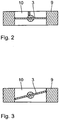
- Figur 2
- eine vereinfachte Ansicht eines Verstell-Körpers der in
Fig. 1 gezeigten Schalldämpfer-Anordnung, wobei sich der Verstell-Körper in seiner Schließ-Stellung befindet, - Figur 3
- den in
Fig. 2 dargestellten Verstell-Körper in dessen Offen-Stellung, und - Figur 4
- eine vereinfachte Darstellung der Steuereinrichtung der Schalldämpfer-Anordnung gemäß
Fig. 1 . - Eine Schalldämpfer-Anordnung umfasst einen Schalldämpfer 1, der ein Abgas-Strömungs-Rohr 2 und einen stromabwärts zu dem Abgas-Strömungs-Rohr 2 angeordneten Verstell-Körper 3 zum Beeinflussen der Strömung des Abgases in dem Abgas-Strömungs-Rohr 2 aufweist. Der Schalldämpfer 1 hat ferner einen Verstell-Antrieb 4, der mit dem Verstell-Körper 3 zum Verstellen desselben in Antriebs-Verbindung steht.
- Die Schalldämpfer-Anordnung weist ferner eine Steuereinrichtung 5 auf, die mit dem Verstell-Antrieb 4 zum Betätigen desselben in datenübertragender Weise in Verbindung steht.
- Das Abgas-Strömungs-Rohr 2 begrenzt einen Abgas-Strömungs-Kanal. Es ist vorzugsweise seitlich von Absorptions-Material 6 umgeben. Ferner weist der Schalldämpfer 1 ein Schalldämpfer-Gehäuse 7 auf, das das Absorptions-Material 6 außen umgibt und im Querschnitt vorzugsweise kreisringförmig ist.
- Der Schalldämpfer 1 weist eingangsseitig ein Anschluss-Stück 8 auf, das an einen Verbrennungsmotor eines Kraftfahrzeugs oder an einen anderen Schalldämpfer anschließbar ist.
- Stromabwärts zu dem Absorptions-Material 6 und dem Abgas-Strömungs-Rohr 2 ist in dem Schalldämpfer-Gehäuse 7 eine Verstell-Körper-Aufnahme 9 angeordnet, die im Querschnitt kreisringförmig ist. Die Verstell-Körper-Aufnahme 9 begrenzt einen Abgas-Durchtritts-Kanal 10, in dem der Verstell-Körper 3 betätigbar untergebracht ist.
- Der Verstell-Körper 3 ist durch eine kreisförmige Klappe gebildet, deren Durchmesser in etwa dem Innen-Durchmesser der Verstell-Körper-Aufnahme 9 entspricht. Er steht mit einem Lagerkörper in drehfester Verbindung, der in der Verstell-Körper-Aufnahme 9 schwenkbar gelagert ist und durch Aufbringen einer externen Verschwenk-Kraft verschwenkbar ist. Der Lagerkörper ist vorzugsweise stiftartig ausgebildet und erstreckt sich senkrecht zu einer Längs-Mittel-Achse 11 des Schalldämpfers 1.
- Der Verstell-Antrieb 4 ist vorzugsweise ein Elektro-Stell-Antrieb oder ein Servo-Antrieb oder ein anderer Gleichstrom-Antrieb. Er hat vorzugsweise eine Antriebs-Welle (nicht dargestellt), die mit dem Verstell-Körper 3 zur Betätigung desselben in Wirk-Verbindung steht. Ferner umfasst der Verstell-Antrieb 4 einen EndAnschlag 12, der vorzugsweise ortsfest an dem Gehäuse des Verstell-Antriebs 4 angebracht ist. Er kann mit einem Mitnehmer (nicht dargestellt) wechselwirken, der an der Antriebs-Welle befestigt ist. Wenn der Mitnehmer an dem EndAnschlag 12 in Anlage kommt, steigt der Strom des Verstell-Antriebs 4. Dies wird dann von der Steuereinrichtung 5 erkannt. Für den Verstell-Antrieb 4 kann alternativ aber auch eine Betätigungszeit einprogrammiert sein, in der er dann in eine Richtung läuft. Eine derartige Ausgestaltung ist technisch äußerst einfach und kostengünstig realisierbar. Der mechanische Anschlag ist aus mechanischen Gründen trotzdem vorteilhaft.
- Nachfolgend wird die Funktion des Schalldämpfers 1 im Betrieb detailliert beschrieben. Dabei wird zunächst auf den Betrieb des Schalldämpfers 1 bei geschlossenem Verstell-Körper 3 eingegangen. Das aus dem Verbrennungsmotor des Kraftfahrzeugs austretende Abgas gelangt über das Anschluss-Stück 8 in das Abgas-Strömungs-Rohr 2. Nachdem sich der Verstell-Körper 3 in seiner Schließ-Stellung befindet und so den Abgas-Durchtritts-Kanal 10 in der Verstell-Körper-Aufnahme 9 vollständig verschließt, strömt das Abgas in einen Bypass-Körper, wo der Schall gedämpft wird. Das Abgas passiert so den Verstell-Körper 3 und verlässt dann den Schalldämpfer 1. Der Bypass-Körper kann ein interner oder externer Bypass-Körper sein. Wenn der Bypass-Körper als interner Bypass-Körper ausgebildet ist, erstreckt er sich innerhalb des Schalldämpfer-Gehäuses 7 und vorzugsweise entlang des Abgas-Strömungs-Rohrs 2. Wenn der Bypass-Körper als externer Bypass-Körper ausgeführt ist, steht dieser mit dem Abgas-Strömungs-Rohr 2 in Strömungsverbindung und erstreckt sich im Wesentlichen außerhalb des Schalldämpfer-Gehäuses 7. Andere Ausgestaltungen sind alternativ möglich.
- Wenn sich der Verstell-Körper 3 dagegen in seiner Öffnungs-Stellung befindet, ist der Abgas-Durchtritts-Kanal 10 freigegeben. Der Verstell-Körper 3 ist hier gegenüber seiner Schließ-Stellung um etwa 90° geschwenkt. Die Schwenk-Bewegung erfolgt durch den Verstell-Antrieb 4. Das Abgas kann so das Abgas-Strömungs-Rohr 2 vollständig axial durchströmen und dabei auch den Abgas-Durchtritts-Kanal 11 durchsetzen. Der Schall wird bei geschlossenem Verstell-Körper 3 stärker gedämpft als bei offenem Verstell-Körper 3. Der Schalldämpfer 1 ist also bei geschlossenem Verstell-Körper 3 leiser als bei offenem Verstell-Körper 3.
- Die Betätigung bzw. Ansteuerung des Verstell-Antriebs 4 erfolgt durch die Steuereinrichtung 5, auf die nun nachfolgend näher eingegangen wird.
- Die Steuereinrichtung 5 hat einen Fahrgeschwindigkeits-Signal-Eingang 13, der mit einem Fahrgeschwindigkeits-Sensor 14 in datenübertragender Weise in Verbindung steht. Der Fahrgeschwindigkeits-Sensor 14 sensiert die aktuelle Fahrgeschwindigkeit des Kraftfahrzeugs. Für die Fahrgeschwindigkeit des Kraftfahrzeugs repräsentative Fahrgeschwindigkeits-Signale werden dann im Betrieb des Kraftfahrzeugs über den Fahrgeschwindigkeits-Signal-Eingang 13 der Steuereinrichtung 5 zugeführt.
- Die Steuereinrichtung 5 hat ferner einen Motordrehzahl-Signal-Eingang 15, der mit einem Motordrehzahl-Sensor 16 in datenübertragender Weise in Verbindung steht. Der Motordrehzahl-Sensor 16 sensiert die aktuelle Motordrehzahl des Verbrennungsmotors des Kraftfahrzeugs. Für die Motordrehzahl repräsentative Motordrehzahl-Signale 15 werden dann bei Betrieb des Kraftfahrzeugs über den Motordrehzahl-Signal-Eingang 15 der Steuereinrichtung 5 zugeführt.
- Die Steuereinrichtung 5 hat außerdem einen Abgasgegendruck-Signal-Eingang 17, der mit einem Abgasgegendruck-Sensor 18 in datenübertragender Weise in Verbindung steht. Der Abgasgegendruck-Sensor 18 sensiert im Betrieb des Kraftfahrzeugs den im Abgas-Strömungs-Rohr 2 aktuell herrschenden Abgasgegendruck. Für den Abgasgegendruck repräsentative Abgasgegendruck-Signale werden dann über den Abgasgegendruck-Signal-Eingang 17 der Steuereinrichtung 5 zugeführt.
- Die Steuereinrichtung 5 hat außerdem einen Eingang 19 für Kraftfahrzeug-unabhängige Signale. Der Eingang 19 steht mit einer Ermittlungs- bzw. Erfassungseinheit 20 in datenübertragender Weise in Verbindung. Die Ermittlungs- bzw. Erfassungseinheit 20 ermittelt bzw. erfasst Kraftfahrzeug-unabhängige Signale, wie Radarwarnsignale, Fahrzyklen oder dergleichen. Diese Signale werden über den Eingang 19 der Steuereinrichtung 5 zugeführt.
- Die Steuereinrichtung 5 hat außerdem einen Eingabe-Eingang 21. Über den Eingabe-Eingang 21 können der Steuereinrichtung 5 verschiedene Werte, wie Schwellenwerte und/oder Kraftfahrzeug-Werte, wie Gewicht, Länge oder dergleichen, zugeführt werden. Mit dem Eingabe-Eingang 21 ist eine entsprechende Eingabe-Einheit 22 verbindbar, die vorzugsweise ein Computer, eine Tastatur oder dergleichen ist.
- Ferner steht ein Tast-Schalter 23 mit der Steuereinrichtung 5 in Verbindung, der zum manuellen Ein- bzw. Ausschalten der geschwindigkeitsabhängigen und/oder drehzahlabhängigen und/oder getriebegangabhängigen Automatik der Steuereinrichtung 5 dient. Insbesondere dient der Tast-Schalter 23 nur zum Aktivieren/Einschalten oder Deaktivieren/ Ausschalten der geschwindigkeits-, drehzahl- und/oder getriebegangabhängigen Automatik der Steuereinrichtung 5. Beim "Deaktivieren" bleibt der Verstell-Körper 3 in seiner Schließ-Stellung.
- Ferner steht ein Auspuffprüf-Taster 24 mit der Steuereinrichtung 5 in Verbindung. Dieser dient zum vollständigen Abschalten der Steuereinrichtung 5. Mit dem Auspuffprüf-Taster 24 ist ein Prüf-Modus in der Steuereinrichtung 5 aktivierbar, welcher die Kontrolle des Verstell-Körpers 3 ohne fahren zu müssen möglich macht. Durch Betätigung des Auspuffprüf-Tasters 24 kann die Funktionsfähigkeit des Schalldämpfers 1 nach Anbau an dem Kraftfahrzeug bzw. zu Wartungsarbeiten geprüft werden.
- Ferner hat die Steuereinrichtung 5 eine Fernbedienung 25, über die sie fernbedienbar ist.
- Über eine Verbindung 26 ist die Steuereinrichtung 5 mit dem Verstell-Antrieb 4 in datenübertragenderweise zum Betätigen desselben verbunden.
- Die Steuereinrichtung 5 umfasst außerdem eine Zentraleinheit 27, die erfindungsgemäß im Betrieb der Steuereinrichtung 5 aus den empfangenen Fahrgeschwindigkeits-Signalen und Motordrehzahl-Signalen die entsprechenden, jeweils vorliegenden Getriebegänge berechnet.
- Nachfolgend wird die Funktion der Steuereinrichtung 5 näher beschrieben. Wie bereits erwähnt, empfängt die Steuereinrichtung 5 Fahrgeschwindigkeits-Signale und Motordrehzahl-Signale. Die Zentraleinheit 27 berechnet durch die empfangenen Fahrgeschwindigkeits-Signale und/oder Motordrehzahl-Signale die Getriebegänge des Kraftfahrzeugs. Es ist bevorzugt, dass die Zentraleinheit 27 die Getriebegänge durch die Fahrgeschwindigkeits-Signale und die Motordrehzahl-Signale berechnet.
- In der Steuereinrichtung 5 sind Fahrgeschwindigkeits-Schwellenwerte, Motordrehzahl-Schwellenwerte und Getriebegang-Schwellenwerte hinterlegt. Anhand dieser Schwellenwerte erfolgt eine Betätigung des Verstell-Körpers 3 über den Verstell-Antrieb 4. Sobald also diese Schwellenwerte überschritten bzw. unterschritten werden, wird der Verstell-Körper 3 durch den Verstell-Antrieb 4 betätigt.
- Die Steuereinrichtung 5 ist erfindungsgemäß derart ausgebildet, dass sie in der Lage ist, den Verstell-Antrieb 4 in Abhängigkeit der Motordrehzahl-Signale, Fahrgeschwindigkeits-Signale und der Getriebegang-Signale zu betätigen. Es sind dann also drei Bedingungen erforderlich, damit die Steuereinrichtung 5 den Verstell-Antrieb 4 betätigt.
- Zusätzlich ist die Steuereinrichtung 5 vorzugsweise derart ausgebildet, dass sie in der Lage ist, den Verstell-Antrieb 4 zusätzlich oder alternativ in Abhängigkeit der Abgasgegendruck-Signale zu betätigen.
- Die Steuereinrichtung 5 berechnet vorzugsweise auch Beschleunigungswerte des Kraftfahrzeugs. Die Beschleunigungswerte können auch entsprechend über mindestens einen Beschleunigungssensor gemessen werden. Vorzugsweise werden die gemessenen Beschleunigungswerte gemittelt.
- In Abhängigkeit der gemessenen Werte werden Geräuschwerte des Schalldämpfers 1 berechnet.
- Der Abgasgegendruck-Signal-Eingang 17 an der Steuereinrichtung 5 in Verbindung mit dem Abgasgegendruck-Sensor 18 ist optional. Der Eingang 19 für die Kraftfahrzeug-unabhängigen Signale an der Steuereinrichtung 5 in Verbindung mit der Ermittlungs- bzw. Erfassungseinheit 20 ist optional. Der Eingabe-Eingang 21 an der Steuereinrichtung 5 ist optional. Die Fernbedienung 25 ist optional. Unter "optional" wird hier verstanden, dass diese Mittel auch weggelassen werden können. Die angegebenen optionalen Mittel könnten aber einzeln oder allesamt bei verschiedenen Ausführungsformen vorhanden sein.
- Nachfolgend sind die Formeln bzw. Bedingungen angegeben, anhand welcher die Steuereinrichtung 5 voneinander unabhängige oder miteinander in Verbindung stehende Befehle zur Betätigung des Verstell-Antriebs 4 abgibt.


- Die Beschleunigung des Kraftfahrzeugs wird anhand von Messungen der Kraftfahrzeuggeschwindigkeit bei den Linien AA' und BB' berechnet:

- Der Index "(i)" bezieht sich auf den verwendeten Getriebegang und der Index "j" auf die Anzahl der Messungen. Die Fahrgeschwindigkeiten werden in der Einheit km/h angegeben und die sich ergebenden Beschleunigungen des Kraftfahrzeugs haben die Einheit m/s2.
- Iref ist entweder die Länge des Kraftfahrzeugs oder 2 m, was von dem Hersteller des Kraftfahrzeugs, die Typzulassungsbehörde bzw. dem technischen Service frei wählbar ist.
- Die Beschleunigung des Kraftfahrzeugs wird anhand der Messungen der Fahrgeschwindigkeit des Kraftfahrzeugs bei den Linien PP' und BB' berechnet:

- Der Index "(i)" bezieht sich auf den verwendeten Getriebegang und der Index "j" auf die Anzahl der Messungen. Die Fahrgeschwindigkeiten werden in der Einheit km/h angegeben und die sich ergebenden Beschleunigungen des Kraftfahrzeugs haben die Einheit m/s2.
- Iref ist entweder die Länge des Kraftfahrzeugs oder 2 m, was von dem Hersteller des Kraftfahrzeugs, die Typzulassungsbehörde bzw. dem technischen Service frei wählbar ist.
- Eine Vor-Beschleunigung des Kraftfahrzeugs soll nicht verwendet werden.
- Die berechneten Beschleunigungen des Kraftfahrzeugs von drei gültigen Läufen werden arithmetisch gemittelt, um die mittlere Beschleunigung des Kraftfahrzeugs für den Testzustand zu liefern:

- Der Getriebegang-Wichtungsfaktor k wird nur im Falle eines Zweigangtests verwendet, um die Ergebnisse von beiden Getriebegängen zu einem einzigen Ergebnis zusammenzufassen.
- Der Getriebegang-Wichtungsfaktor k ist eine dimensionslose Zahl, die wie folgt definiert ist:

- Der Teilleistungsfaktor kp ist eine dimensionslose Zahl, die verwendet wird, um die Ergebnisse eines Volllast-Beschleunigungstests mit den Ergebnissen eines Konstant-Geschwindigkeitstests zu vereinen. Für Kraftfahrzeuge, die in zwei Getriebegängen getestet worden sind, ist der Teilleistungsfaktor wie folgt definiert:

- Für Kraftfahrzeuge, die in einem einzigen Getriebegang oder mit einem Gangwahlmittel in einer Position getestet worden sind, ist der Teilleistungsfaktor wie folgt definiert:

- Falls awot,(i) gleich oder kleiner als aurban ist, wird kp auf Null gesetzt.
- Für einen gegebenen Testzustand sollen die drei einzelnen Ergebnisse von jeder Seite des Kraftfahrzeugs separat gemittelt werden:

- Der Index "Mode" bezieht sich auf den Testmodus (Volllast-Beschleunigung oder konstante Geschwindigkeit).
- Der Index "(i)" bezieht sich auf den Getriebegang und "side" auf die Position des Mikrophons (links oder rechts).
- Der höhere Wert der zwei Mittelungen soll mathematisch auf die nächste, erste Dezimalstelle (beispielsweise XX.X) gerundet werden und für weitere Berechnungen vermerkt werden:

- Falls das Kraftfahrzeug in zwei Getriebegängen getestet worden ist, wird der Getriebegang-Wichtungsfaktor verwendet, um die Testergebnisse der Volllast-Beschleunigungstests und der Tests mit konstanter Geschwindigkeit zu berechnen:


- Falls das Kraftfahrzeug in einem einzelnen Getriebegang oder einer einzelnen Getriebegang-Wahlposition getestet worden ist, ist kein Wichtungsfaktor erforderlich:


- Nachfolgend sind weitere Erklärungen zu den obigen Abkürzungen angegeben:
- AA
- virtuelle Linie auf der Testbahn
- awot m/s2
- berechnete Beschleunigung
- awot,ref m/s2
- vorgegebene Referenzbeschleunigung
- aurban m/s2 v
- vorgegebene Zielbeschleunigung
- BB'
- virtuelle Linie auf der Testbahn
- CC
- virtuelle Linie auf der Testbahn
- k
- Getriebegang-Wichtungsfaktor
- kp
- Teillastfakor
- L dB(A)
- Schalldruckwert
- IPA m
- Vor-Beschleunigungslänge
- mkerb kg
- fahrfertiges Gewicht des Kraftfahrzeugs mit vollem Tank ohne Insassen
- mt kg
- Testgewicht des Kraftfahrzeugs
- n min-1
- gemessene Motordrehzahl
- nidle min-1
- Motordrehzahl bei Leerlauf
- nwot(i) min-1 nPP'
- entspricht Lwot(i) Annex
- PP'
- virtuelle Linie auf der Testbahn Annex 4
- PMR
- Leistung zu Masse - Verhältnisindex
- Pn kW
- bewertete maximale Leistung
- S min-1
- bewertete Motordrehzahl
- v km/h
- gemessene Geschwindigkeit des Kraftfahrzeugs
- vmax km/h
- maximale Geschwindigkeit
- vtest km/h
- vorgegebene Testgeschwindigkeit
Claims (10)
- Schalldämpfer-Anordnung für Auspuffanlagen von Kraftfahrzeugen mit Verbrennungsmotor, umfassenda. einen Schalldämpfer (1) miti. einem Abgas-Strömungs-Rohr (2) zur Führung von Abgas, das aufweist- mindestens eine Abgas-Einlass-Öffnung und- mindestens eine Abgas-Auslass-Öffnung, die mit der mindestens einen Abgas-Einlass-Öffnung in Strömungsverbindung steht,ii. mindestens einem zwischen einer Öffnungs-Stellung und einer Schließ-Stellung verstellbaren Verstell-Körper (3) zum Beeinflussen der Abgas-Strömung in dem Abgas-Strömungs-Rohr (2), undiii. mindestens einem Verstell-Antrieb (4), der mit dem mindestens einen Verstell-Körper (3) zur Verstellung desselben in Verbindung steht, undb. eine Steuereinrichtung (5), diedie Steuereinrichtung (5) den mindestens einen Verstell-Antrieb (4) in Abhängigkeit der Fahrgeschwindigkeits-Signale und der Motordrehzahl-Signale sowie von Getriebegang-Signalen des Kraftfahrzeugs zur Verstellung des mindestens einen Verstell-Körpers (3) betätigt.i. einen Fahrgeschwindigkeits-Signal-Eingang (13) zum Empfangen von Fahrgeschwindigkeits-Signalen des Kraftfahrzeugs aufweist,ii. einen Motordrehzahl-Signal-Eingang (15) zum Empfangen von Motordrehzahl-Signalen des Kraftfahrzeugs aufweist, undiii. mit dem mindestens einen Verstell-Antrieb (4) zur Verstellung des mindestens einen Verstell-Körpers (3) in datenübertragender Weise in Verbindung steht, wobei die Steuereinrichtung (5) in Abhängigkeit der Fahrgeschwindigkeits-Signale und/oder der Motordrehzahl-Signale die Getriebegang-Signale berechnet, und
- Schalldämpfer-Anordnung nach Anspruch 1, dadurch gekennzeichnet, dass die Steuereinrichtung (5) einen Abgasgegendruck-Signal-Eingang (17) zum Empfangen von Signalen aufweist, die repräsentativ für den Abgasgegendruck in dem Abgas-Strömungs-Rohr (2) sind.
- Schalldämpfer-Anordnung nach Anspruch 2, dadurch gekennzeichnet, dass die Steuereinrichtung (5) den mindestens einen Verstell-Antrieb (4) in Abhängigkeit der Abgasgegendruck-Signale zur Verstellung des mindestens einen Verstell-Körpers (3) betätigt.
- Schalldämpfer-Anordnung nach einem der vorherigen Ansprüche, dadurch gekennzeichnet, dass die Steuereinrichtung (5) einen Eingang (19) für Kraftfahrzeug-unabhängige Signale aufweist.
- Schalldämpfer-Anordnung nach einem der vorherigen Ansprüche, dadurch gekennzeichnet, dass die Steuereinrichtung (5) einen Eingabe-Eingang (21) zur Eingabe von Werten aufweist.
- Schalldämpfer-Anordnung nach einem der vorherigen Ansprüche, dadurch gekennzeichnet, dass in der Steuereinrichtung (5) mindestens ein Fahrgeschwindigkeits-Schwellenwert zur Betätigung des mindestens einen Verstell-Antriebs (4) enthalten ist, wobei vorzugsweise der mindestens eine Fahrgeschwindigkeits-Schwellenwert vorbestimmt oder veränderlich ist.
- Schalldämpfer-Anordnung nach einem der vorherigen Ansprüche, dadurch gekennzeichnet, dass in der Steuereinrichtung (5) mindestens ein Motordrehzahl-Schwellenwert zur Betätigung des mindestens einen Verstell-Antriebs (4) enthalten ist, wobei vorzugsweise der mindestens eine Motordrehzahl-Schwellenwert vorbestimmt oder veränderlich ist.
- Schalldämpfer-Anordnung nach einem der vorherigen Ansprüche, dadurch gekennzeichnet, dass in der Steuereinrichtung (5) mindestens ein Getriebegang-Schwellenwert zur Betätigung des mindestens einen Verstell-Antriebs (4) enthalten ist.
- Schalldämpfer-Anordnung nach einem der vorherigen Ansprüche, dadurch gekennzeichnet, dass die Steuereinrichtung (5) fernbedienbar ist.
- Schalldämpfer-Anordnung nach einem der vorherigen Ansprüche, dadurch gekennzeichnet, dass die Verstellung des mindestens einen Verstell-Körpers (3) zeitlich verzögert erfolgt, wobei die Verzögerungszeit vorzugsweise einstellbar ist.
Applications Claiming Priority (2)
| Application Number | Priority Date | Filing Date | Title |
|---|---|---|---|
| DE102012200456A DE102012200456A1 (de) | 2012-01-13 | 2012-01-13 | Schalldämpfer-Anordnung |
| PCT/EP2013/050339 WO2013104689A1 (de) | 2012-01-13 | 2013-01-10 | Schalldämpfer-anordnung |
Publications (2)
| Publication Number | Publication Date |
|---|---|
| EP2802750A1 EP2802750A1 (de) | 2014-11-19 |
| EP2802750B1 true EP2802750B1 (de) | 2017-03-15 |
Family
ID=47553072
Family Applications (1)
| Application Number | Title | Priority Date | Filing Date |
|---|---|---|---|
| EP13700155.8A Active EP2802750B1 (de) | 2012-01-13 | 2013-01-10 | Schalldämpfer-anordnung |
Country Status (3)
| Country | Link |
|---|---|
| EP (1) | EP2802750B1 (de) |
| DE (1) | DE102012200456A1 (de) |
| WO (1) | WO2013104689A1 (de) |
Cited By (1)
| Publication number | Priority date | Publication date | Assignee | Title |
|---|---|---|---|---|
| DE102021115261A1 (de) | 2021-06-14 | 2022-12-15 | Bayerische Motoren Werke Aktiengesellschaft | Verfahren zum Betreiben eines Kraftfahrzeugs sowie Kraftfahrzeug |
Families Citing this family (3)
| Publication number | Priority date | Publication date | Assignee | Title |
|---|---|---|---|---|
| US10443479B2 (en) * | 2014-10-30 | 2019-10-15 | Roush Enterprises, Inc. | Exhaust control system |
| WO2017079156A1 (en) | 2015-11-02 | 2017-05-11 | Roush Enterprises, Inc. | Muffler with selected exhaust pathways |
| DE202018103103U1 (de) | 2018-06-01 | 2018-06-07 | Kesstech Gmbh | Schalldämpferanordnung |
Citations (9)
| Publication number | Priority date | Publication date | Assignee | Title |
|---|---|---|---|---|
| EP0479342A2 (de) | 1986-09-13 | 1992-04-08 | Yamaha Motor Co., Ltd. | Hochleistungsauspuffanlage für Brennkraftmaschinen |
| DE4218523C1 (en) | 1992-06-05 | 1993-04-15 | Mercedes-Benz Aktiengesellschaft, 7000 Stuttgart, De | Catalyst appts. allowing easy operation of temp. - includes main exhaust gas line, thin by=pass line, exhaust gas line and control unit |
| EP1455068A2 (de) | 2003-03-03 | 2004-09-08 | Dr.Ing. h.c.F. Porsche Aktiengesellschaft | Abgasleitung einer Brennkraftmaschine mit steuerbaren Abgasklappen |
| DE102005029279A1 (de) | 2004-06-30 | 2006-01-19 | Harley-Davidson Motor Company Group, Inc., Milwaukee | Dynamisches Abgassystem für ein Motorrad |
| DE102005029763A1 (de) | 2005-06-27 | 2006-12-28 | Dr.Ing.H.C. F. Porsche Ag | Verfahren zum Betätigen eines Umsteuerorgans einer Abgasanlage für ein Fahrzeug |
| DE102006044381A1 (de) | 2005-09-23 | 2007-04-05 | Müller, Werner | Abgasvorrichtung mit sekundärer Leistungs- bzw. Drehmomentsteuerung bzw. -regelung |
| DE102007014446A1 (de) | 2007-03-27 | 2008-10-02 | Dr. Ing. H.C. F. Porsche Aktiengesellschaft | Abgasanlage einer Brennkraftmaschine sowie Verfahren zur Erzeugung einer bestimmten Abgasfrequenz in einer Abgasanlage |
| EP1978216A2 (de) | 2007-04-04 | 2008-10-08 | Nissan Motor Co., Ltd. | Verfahren und Gerät zur Steuerung des Motorabgasgeräuschs von Fahrzeugen |
| WO2012072789A1 (de) | 2010-12-02 | 2012-06-07 | Kess-Tech Gmbh | Schalldämpfer für auspuff-anlagen |
Family Cites Families (5)
| Publication number | Priority date | Publication date | Assignee | Title |
|---|---|---|---|---|
| SE517825C2 (sv) * | 1997-11-14 | 2002-07-23 | Volvo Car Corp | Anordning och förfarande vid ljuddämpande enhet samt användning av anordningen vid ett motorfordon |
| DE19840096A1 (de) * | 1998-09-03 | 2000-03-09 | Porsche Ag | Abgasanlage einer mehrzylindrigen Brennkraftmaschine |
| DE10228045A1 (de) * | 2002-06-24 | 2004-01-15 | Volkswagen Ag | Nachschalldämpfer für eine Abgasanlage einer Brennkraftmaschine und Verfahren zum Betreiben dieser |
| DE202005011448U1 (de) | 2005-07-18 | 2006-11-23 | Kess, Roland | Schalldämpfer-Auslassteil für einen Motorrad-Schalldämpfer |
| EP2317116B1 (de) * | 2008-06-30 | 2012-07-11 | Honda Motor Co., Ltd. | Zweirädriges kraftfahrzeug |
-
2012
- 2012-01-13 DE DE102012200456A patent/DE102012200456A1/de not_active Withdrawn
-
2013
- 2013-01-10 WO PCT/EP2013/050339 patent/WO2013104689A1/de active Application Filing
- 2013-01-10 EP EP13700155.8A patent/EP2802750B1/de active Active
Patent Citations (9)
| Publication number | Priority date | Publication date | Assignee | Title |
|---|---|---|---|---|
| EP0479342A2 (de) | 1986-09-13 | 1992-04-08 | Yamaha Motor Co., Ltd. | Hochleistungsauspuffanlage für Brennkraftmaschinen |
| DE4218523C1 (en) | 1992-06-05 | 1993-04-15 | Mercedes-Benz Aktiengesellschaft, 7000 Stuttgart, De | Catalyst appts. allowing easy operation of temp. - includes main exhaust gas line, thin by=pass line, exhaust gas line and control unit |
| EP1455068A2 (de) | 2003-03-03 | 2004-09-08 | Dr.Ing. h.c.F. Porsche Aktiengesellschaft | Abgasleitung einer Brennkraftmaschine mit steuerbaren Abgasklappen |
| DE102005029279A1 (de) | 2004-06-30 | 2006-01-19 | Harley-Davidson Motor Company Group, Inc., Milwaukee | Dynamisches Abgassystem für ein Motorrad |
| DE102005029763A1 (de) | 2005-06-27 | 2006-12-28 | Dr.Ing.H.C. F. Porsche Ag | Verfahren zum Betätigen eines Umsteuerorgans einer Abgasanlage für ein Fahrzeug |
| DE102006044381A1 (de) | 2005-09-23 | 2007-04-05 | Müller, Werner | Abgasvorrichtung mit sekundärer Leistungs- bzw. Drehmomentsteuerung bzw. -regelung |
| DE102007014446A1 (de) | 2007-03-27 | 2008-10-02 | Dr. Ing. H.C. F. Porsche Aktiengesellschaft | Abgasanlage einer Brennkraftmaschine sowie Verfahren zur Erzeugung einer bestimmten Abgasfrequenz in einer Abgasanlage |
| EP1978216A2 (de) | 2007-04-04 | 2008-10-08 | Nissan Motor Co., Ltd. | Verfahren und Gerät zur Steuerung des Motorabgasgeräuschs von Fahrzeugen |
| WO2012072789A1 (de) | 2010-12-02 | 2012-06-07 | Kess-Tech Gmbh | Schalldämpfer für auspuff-anlagen |
Non-Patent Citations (1)
| Title |
|---|
| ANONYMOUS: "Yamaha Technologie 1987: EXUP-Exhaust Ultimate Power Valve", YAMAHA, 15 April 2009 (2009-04-15), pages 1, Retrieved from the Internet <URL:https://www.yamaha-motor.eu/designcafe/de/archive/archived-articles/index.aspx?view=article&id=441168> |
Cited By (1)
| Publication number | Priority date | Publication date | Assignee | Title |
|---|---|---|---|---|
| DE102021115261A1 (de) | 2021-06-14 | 2022-12-15 | Bayerische Motoren Werke Aktiengesellschaft | Verfahren zum Betreiben eines Kraftfahrzeugs sowie Kraftfahrzeug |
Also Published As
| Publication number | Publication date |
|---|---|
| WO2013104689A1 (de) | 2013-07-18 |
| DE102012200456A1 (de) | 2013-07-18 |
| EP2802750A1 (de) | 2014-11-19 |
Similar Documents
| Publication | Publication Date | Title |
|---|---|---|
| EP2802750B1 (de) | Schalldämpfer-anordnung | |
| EP1980441B1 (de) | Steuerknüppel für ein Fahrzeug | |
| EP2232458B1 (de) | Verfahren und vorrichtung zur unterstützung eines fahrzeugbedieners | |
| DE19720131B4 (de) | Fahrsituationsabhängige Standabkopplung | |
| DE102008017350B4 (de) | Steuerung für Fahrmischer | |
| DE60123017T2 (de) | Pedalvorrichtung für Kraftfahrzeuge und Kraftfahrzeug mit einer solchen Vorrichtung | |
| DE112008003174T5 (de) | Verfahren zum Betreiben eines hydrostatisch angetriebenen Fahrzeugs | |
| EP2159121B1 (de) | Steuereinrichtung und Verfahren zur Durchführung eines automatischen Einparkvorgangs | |
| DE102011002997A1 (de) | Verfahren zum Erkennen einer freihändigen Fahrsituation eines Kraftfahrzeuges | |
| DE102014207566A1 (de) | KFZ-Luftklappenanordnung mit sensorischer Stellungserfassung | |
| DE102017110942A1 (de) | Feststellbremsanlage für ein Kraftfahrzeug und Kraftfahrzeug | |
| EP3001411B1 (de) | Überlastungsschutz für einen aktor eines systems zur beeinflussung von in einer abgasanlage geführtem schall | |
| EP0892725B1 (de) | Einrichtung für den ökonomischen betrieb von kraftfahrzeugen | |
| EP2646660B2 (de) | Schalldämpfer für auspuff-anlagen | |
| WO2008019645A1 (de) | Verfahren zur abstandsregelung | |
| EP1195612B1 (de) | Erkennung eines Fahrzeug-Nebenantriebs | |
| EP4025438A1 (de) | Steuergerät für eine anhängekupplung mit hindernisüberwachung | |
| DE102016207002A1 (de) | Verfahren und Vorrichtung zur Steuerung einer Abgasklappe | |
| DE10214598B4 (de) | Fahrantrieb für eine landwirtschaftliche Erntemaschine mit Steuerung der Fahrgeschwindigkeit bei Straßenfahrten | |
| WO2004020239A1 (de) | Vorrichtung und verfahren zur längsführung eines kraftfahrzeugs | |
| DE102008018472B3 (de) | Geschwindigkeitsregelvorrichtung mit Abschaltung zum Gangwechsel | |
| DE102018204358B4 (de) | Steuerverfahren zum Betreiben eines Kraftfahrzeugs, Steuereinheit für ein Kraftfahrzeug sowie Kraftfahrzeug mit einer derartigen Steuereinheit | |
| DE102007056592A1 (de) | Abstandskontrollsystem | |
| DE102020125229A1 (de) | Fernbedienbares Verfahrsystem zum automatisierten Verfahren eines Kraftfahrzeugs mit Distanzbestimmung zwischen Fernbedienung und Kraftfahrzeug, entsprechendes Verfahren und entsprechende Software | |
| EP3135960B1 (de) | Schalteinrichtung zur betätigung eines schaltgetriebes eines motorrads zur durchführung eines gangwechsels bei geschlossener kupplung |
Legal Events
| Date | Code | Title | Description |
|---|---|---|---|
| PUAI | Public reference made under article 153(3) epc to a published international application that has entered the european phase |
Free format text: ORIGINAL CODE: 0009012 |
|
| 17P | Request for examination filed |
Effective date: 20140710 |
|
| AK | Designated contracting states |
Kind code of ref document: A1 Designated state(s): AL AT BE BG CH CY CZ DE DK EE ES FI FR GB GR HR HU IE IS IT LI LT LU LV MC MK MT NL NO PL PT RO RS SE SI SK SM TR |
|
| DAX | Request for extension of the european patent (deleted) | ||
| RAP3 | Party data changed (applicant data changed or rights of an application transferred) |
Owner name: KESSTECH GMBH |
|
| GRAP | Despatch of communication of intention to grant a patent |
Free format text: ORIGINAL CODE: EPIDOSNIGR1 |
|
| INTG | Intention to grant announced |
Effective date: 20160602 |
|
| GRAJ | Information related to disapproval of communication of intention to grant by the applicant or resumption of examination proceedings by the epo deleted |
Free format text: ORIGINAL CODE: EPIDOSDIGR1 |
|
| GRAP | Despatch of communication of intention to grant a patent |
Free format text: ORIGINAL CODE: EPIDOSNIGR1 |
|
| INTC | Intention to grant announced (deleted) | ||
| INTG | Intention to grant announced |
Effective date: 20161013 |
|
| STAA | Information on the status of an ep patent application or granted ep patent |
Free format text: STATUS: GRANT OF PATENT IS INTENDED |
|
| GRAS | Grant fee paid |
Free format text: ORIGINAL CODE: EPIDOSNIGR3 |
|
| GRAA | (expected) grant |
Free format text: ORIGINAL CODE: 0009210 |
|
| STAA | Information on the status of an ep patent application or granted ep patent |
Free format text: STATUS: THE PATENT HAS BEEN GRANTED |
|
| AK | Designated contracting states |
Kind code of ref document: B1 Designated state(s): AL AT BE BG CH CY CZ DE DK EE ES FI FR GB GR HR HU IE IS IT LI LT LU LV MC MK MT NL NO PL PT RO RS SE SI SK SM TR |
|
| REG | Reference to a national code |
Ref country code: CH Ref legal event code: EP Ref country code: GB Ref legal event code: FG4D Free format text: NOT ENGLISH |
|
| REG | Reference to a national code |
Ref country code: IE Ref legal event code: FG4D Free format text: LANGUAGE OF EP DOCUMENT: GERMAN |
|
| REG | Reference to a national code |
Ref country code: AT Ref legal event code: REF Ref document number: 875832 Country of ref document: AT Kind code of ref document: T Effective date: 20170415 |
|
| REG | Reference to a national code |
Ref country code: DE Ref legal event code: R096 Ref document number: 502013006652 Country of ref document: DE |
|
| REG | Reference to a national code |
Ref country code: NL Ref legal event code: MP Effective date: 20170315 |
|
| REG | Reference to a national code |
Ref country code: LT Ref legal event code: MG4D |
|
| PG25 | Lapsed in a contracting state [announced via postgrant information from national office to epo] |
Ref country code: LT Free format text: LAPSE BECAUSE OF FAILURE TO SUBMIT A TRANSLATION OF THE DESCRIPTION OR TO PAY THE FEE WITHIN THE PRESCRIBED TIME-LIMIT Effective date: 20170315 Ref country code: FI Free format text: LAPSE BECAUSE OF FAILURE TO SUBMIT A TRANSLATION OF THE DESCRIPTION OR TO PAY THE FEE WITHIN THE PRESCRIBED TIME-LIMIT Effective date: 20170315 Ref country code: GR Free format text: LAPSE BECAUSE OF FAILURE TO SUBMIT A TRANSLATION OF THE DESCRIPTION OR TO PAY THE FEE WITHIN THE PRESCRIBED TIME-LIMIT Effective date: 20170616 Ref country code: NO Free format text: LAPSE BECAUSE OF FAILURE TO SUBMIT A TRANSLATION OF THE DESCRIPTION OR TO PAY THE FEE WITHIN THE PRESCRIBED TIME-LIMIT Effective date: 20170615 Ref country code: HR Free format text: LAPSE BECAUSE OF FAILURE TO SUBMIT A TRANSLATION OF THE DESCRIPTION OR TO PAY THE FEE WITHIN THE PRESCRIBED TIME-LIMIT Effective date: 20170315 |
|
| PG25 | Lapsed in a contracting state [announced via postgrant information from national office to epo] |
Ref country code: BG Free format text: LAPSE BECAUSE OF FAILURE TO SUBMIT A TRANSLATION OF THE DESCRIPTION OR TO PAY THE FEE WITHIN THE PRESCRIBED TIME-LIMIT Effective date: 20170615 Ref country code: SE Free format text: LAPSE BECAUSE OF FAILURE TO SUBMIT A TRANSLATION OF THE DESCRIPTION OR TO PAY THE FEE WITHIN THE PRESCRIBED TIME-LIMIT Effective date: 20170315 Ref country code: RS Free format text: LAPSE BECAUSE OF FAILURE TO SUBMIT A TRANSLATION OF THE DESCRIPTION OR TO PAY THE FEE WITHIN THE PRESCRIBED TIME-LIMIT Effective date: 20170315 Ref country code: LV Free format text: LAPSE BECAUSE OF FAILURE TO SUBMIT A TRANSLATION OF THE DESCRIPTION OR TO PAY THE FEE WITHIN THE PRESCRIBED TIME-LIMIT Effective date: 20170315 |
|
| PG25 | Lapsed in a contracting state [announced via postgrant information from national office to epo] |
Ref country code: NL Free format text: LAPSE BECAUSE OF FAILURE TO SUBMIT A TRANSLATION OF THE DESCRIPTION OR TO PAY THE FEE WITHIN THE PRESCRIBED TIME-LIMIT Effective date: 20170315 |
|
| PG25 | Lapsed in a contracting state [announced via postgrant information from national office to epo] |
Ref country code: CZ Free format text: LAPSE BECAUSE OF FAILURE TO SUBMIT A TRANSLATION OF THE DESCRIPTION OR TO PAY THE FEE WITHIN THE PRESCRIBED TIME-LIMIT Effective date: 20170315 Ref country code: RO Free format text: LAPSE BECAUSE OF FAILURE TO SUBMIT A TRANSLATION OF THE DESCRIPTION OR TO PAY THE FEE WITHIN THE PRESCRIBED TIME-LIMIT Effective date: 20170315 Ref country code: SK Free format text: LAPSE BECAUSE OF FAILURE TO SUBMIT A TRANSLATION OF THE DESCRIPTION OR TO PAY THE FEE WITHIN THE PRESCRIBED TIME-LIMIT Effective date: 20170315 Ref country code: EE Free format text: LAPSE BECAUSE OF FAILURE TO SUBMIT A TRANSLATION OF THE DESCRIPTION OR TO PAY THE FEE WITHIN THE PRESCRIBED TIME-LIMIT Effective date: 20170315 |
|
| PG25 | Lapsed in a contracting state [announced via postgrant information from national office to epo] |
Ref country code: IS Free format text: LAPSE BECAUSE OF FAILURE TO SUBMIT A TRANSLATION OF THE DESCRIPTION OR TO PAY THE FEE WITHIN THE PRESCRIBED TIME-LIMIT Effective date: 20170715 Ref country code: PL Free format text: LAPSE BECAUSE OF FAILURE TO SUBMIT A TRANSLATION OF THE DESCRIPTION OR TO PAY THE FEE WITHIN THE PRESCRIBED TIME-LIMIT Effective date: 20170315 Ref country code: PT Free format text: LAPSE BECAUSE OF FAILURE TO SUBMIT A TRANSLATION OF THE DESCRIPTION OR TO PAY THE FEE WITHIN THE PRESCRIBED TIME-LIMIT Effective date: 20170717 Ref country code: SM Free format text: LAPSE BECAUSE OF FAILURE TO SUBMIT A TRANSLATION OF THE DESCRIPTION OR TO PAY THE FEE WITHIN THE PRESCRIBED TIME-LIMIT Effective date: 20170315 |
|
| REG | Reference to a national code |
Ref country code: DE Ref legal event code: R026 Ref document number: 502013006652 Country of ref document: DE |
|
| PLBI | Opposition filed |
Free format text: ORIGINAL CODE: 0009260 |
|
| PLAX | Notice of opposition and request to file observation + time limit sent |
Free format text: ORIGINAL CODE: EPIDOSNOBS2 |
|
| REG | Reference to a national code |
Ref country code: FR Ref legal event code: PLFP Year of fee payment: 6 |
|
| 26 | Opposition filed |
Opponent name: SCHADE, MIRKO Effective date: 20171215 |
|
| PG25 | Lapsed in a contracting state [announced via postgrant information from national office to epo] |
Ref country code: DK Free format text: LAPSE BECAUSE OF FAILURE TO SUBMIT A TRANSLATION OF THE DESCRIPTION OR TO PAY THE FEE WITHIN THE PRESCRIBED TIME-LIMIT Effective date: 20170315 |
|
| PG25 | Lapsed in a contracting state [announced via postgrant information from national office to epo] |
Ref country code: IT Free format text: LAPSE BECAUSE OF FAILURE TO SUBMIT A TRANSLATION OF THE DESCRIPTION OR TO PAY THE FEE WITHIN THE PRESCRIBED TIME-LIMIT Effective date: 20170315 Ref country code: SI Free format text: LAPSE BECAUSE OF FAILURE TO SUBMIT A TRANSLATION OF THE DESCRIPTION OR TO PAY THE FEE WITHIN THE PRESCRIBED TIME-LIMIT Effective date: 20170315 |
|
| PLAF | Information modified related to communication of a notice of opposition and request to file observations + time limit |
Free format text: ORIGINAL CODE: EPIDOSCOBS2 |
|
| PLBB | Reply of patent proprietor to notice(s) of opposition received |
Free format text: ORIGINAL CODE: EPIDOSNOBS3 |
|
| GBPC | Gb: european patent ceased through non-payment of renewal fee |
Effective date: 20180110 |
|
| PG25 | Lapsed in a contracting state [announced via postgrant information from national office to epo] |
Ref country code: MT Free format text: LAPSE BECAUSE OF FAILURE TO SUBMIT A TRANSLATION OF THE DESCRIPTION OR TO PAY THE FEE WITHIN THE PRESCRIBED TIME-LIMIT Effective date: 20170315 |
|
| PG25 | Lapsed in a contracting state [announced via postgrant information from national office to epo] |
Ref country code: LU Free format text: LAPSE BECAUSE OF NON-PAYMENT OF DUE FEES Effective date: 20180110 |
|
| REG | Reference to a national code |
Ref country code: IE Ref legal event code: MM4A |
|
| REG | Reference to a national code |
Ref country code: BE Ref legal event code: MM Effective date: 20180131 |
|
| PG25 | Lapsed in a contracting state [announced via postgrant information from national office to epo] |
Ref country code: GB Free format text: LAPSE BECAUSE OF NON-PAYMENT OF DUE FEES Effective date: 20180110 Ref country code: BE Free format text: LAPSE BECAUSE OF NON-PAYMENT OF DUE FEES Effective date: 20180131 |
|
| PG25 | Lapsed in a contracting state [announced via postgrant information from national office to epo] |
Ref country code: IE Free format text: LAPSE BECAUSE OF NON-PAYMENT OF DUE FEES Effective date: 20180110 |
|
| PLCK | Communication despatched that opposition was rejected |
Free format text: ORIGINAL CODE: EPIDOSNREJ1 |
|
| REG | Reference to a national code |
Ref country code: DE Ref legal event code: R100 Ref document number: 502013006652 Country of ref document: DE |
|
| PG25 | Lapsed in a contracting state [announced via postgrant information from national office to epo] |
Ref country code: MC Free format text: LAPSE BECAUSE OF FAILURE TO SUBMIT A TRANSLATION OF THE DESCRIPTION OR TO PAY THE FEE WITHIN THE PRESCRIBED TIME-LIMIT Effective date: 20170315 |
|
| PLBN | Opposition rejected |
Free format text: ORIGINAL CODE: 0009273 |
|
| STAA | Information on the status of an ep patent application or granted ep patent |
Free format text: STATUS: OPPOSITION REJECTED |
|
| 27O | Opposition rejected |
Effective date: 20190321 |
|
| PG25 | Lapsed in a contracting state [announced via postgrant information from national office to epo] |
Ref country code: ES Free format text: LAPSE BECAUSE OF FAILURE TO SUBMIT A TRANSLATION OF THE DESCRIPTION OR TO PAY THE FEE WITHIN THE PRESCRIBED TIME-LIMIT Effective date: 20170315 |
|
| PG25 | Lapsed in a contracting state [announced via postgrant information from national office to epo] |
Ref country code: TR Free format text: LAPSE BECAUSE OF FAILURE TO SUBMIT A TRANSLATION OF THE DESCRIPTION OR TO PAY THE FEE WITHIN THE PRESCRIBED TIME-LIMIT Effective date: 20170315 |
|
| PG25 | Lapsed in a contracting state [announced via postgrant information from national office to epo] |
Ref country code: HU Free format text: LAPSE BECAUSE OF FAILURE TO SUBMIT A TRANSLATION OF THE DESCRIPTION OR TO PAY THE FEE WITHIN THE PRESCRIBED TIME-LIMIT; INVALID AB INITIO Effective date: 20130110 |
|
| PG25 | Lapsed in a contracting state [announced via postgrant information from national office to epo] |
Ref country code: MK Free format text: LAPSE BECAUSE OF NON-PAYMENT OF DUE FEES Effective date: 20170315 Ref country code: CY Free format text: LAPSE BECAUSE OF FAILURE TO SUBMIT A TRANSLATION OF THE DESCRIPTION OR TO PAY THE FEE WITHIN THE PRESCRIBED TIME-LIMIT Effective date: 20170315 |
|
| PG25 | Lapsed in a contracting state [announced via postgrant information from national office to epo] |
Ref country code: AL Free format text: LAPSE BECAUSE OF FAILURE TO SUBMIT A TRANSLATION OF THE DESCRIPTION OR TO PAY THE FEE WITHIN THE PRESCRIBED TIME-LIMIT Effective date: 20170315 |
|
| PGFP | Annual fee paid to national office [announced via postgrant information from national office to epo] |
Ref country code: AT Payment date: 20210121 Year of fee payment: 9 |
|
| REG | Reference to a national code |
Ref country code: AT Ref legal event code: MM01 Ref document number: 875832 Country of ref document: AT Kind code of ref document: T Effective date: 20220110 |
|
| PG25 | Lapsed in a contracting state [announced via postgrant information from national office to epo] |
Ref country code: AT Free format text: LAPSE BECAUSE OF NON-PAYMENT OF DUE FEES Effective date: 20220110 |
|
| PGFP | Annual fee paid to national office [announced via postgrant information from national office to epo] |
Ref country code: FR Payment date: 20230124 Year of fee payment: 11 |
|
| PGFP | Annual fee paid to national office [announced via postgrant information from national office to epo] |
Ref country code: DE Payment date: 20240131 Year of fee payment: 12 Ref country code: CH Payment date: 20240202 Year of fee payment: 12 |