EP2802472B1 - Kfz-dichtung - Google Patents
Kfz-dichtung Download PDFInfo
- Publication number
- EP2802472B1 EP2802472B1 EP13708659.1A EP13708659A EP2802472B1 EP 2802472 B1 EP2802472 B1 EP 2802472B1 EP 13708659 A EP13708659 A EP 13708659A EP 2802472 B1 EP2802472 B1 EP 2802472B1
- Authority
- EP
- European Patent Office
- Prior art keywords
- adhesive
- strand
- layer
- material layer
- assembly according
- Prior art date
- Legal status (The legal status is an assumption and is not a legal conclusion. Google has not performed a legal analysis and makes no representation as to the accuracy of the status listed.)
- Active
Links
Images


Classifications
-
- E—FIXED CONSTRUCTIONS
- E06—DOORS, WINDOWS, SHUTTERS, OR ROLLER BLINDS IN GENERAL; LADDERS
- E06B—FIXED OR MOVABLE CLOSURES FOR OPENINGS IN BUILDINGS, VEHICLES, FENCES OR LIKE ENCLOSURES IN GENERAL, e.g. DOORS, WINDOWS, BLINDS, GATES
- E06B7/00—Special arrangements or measures in connection with doors or windows
- E06B7/16—Sealing arrangements on wings or parts co-operating with the wings
- E06B7/22—Sealing arrangements on wings or parts co-operating with the wings by means of elastic edgings, e.g. elastic rubber tubes; by means of resilient edgings, e.g. felt or plush strips, resilient metal strips
- E06B7/23—Plastic, sponge rubber, or like strips or tubes
- E06B7/2314—Plastic, sponge rubber, or like strips or tubes characterised by the material
-
- B—PERFORMING OPERATIONS; TRANSPORTING
- B60—VEHICLES IN GENERAL
- B60J—WINDOWS, WINDSCREENS, NON-FIXED ROOFS, DOORS, OR SIMILAR DEVICES FOR VEHICLES; REMOVABLE EXTERNAL PROTECTIVE COVERINGS SPECIALLY ADAPTED FOR VEHICLES
- B60J10/00—Sealing arrangements
- B60J10/30—Sealing arrangements characterised by the fastening means
- B60J10/34—Sealing arrangements characterised by the fastening means using adhesives
- B60J10/35—Sealing arrangements characterised by the fastening means using adhesives using adhesive tapes, e.g. double-sided tapes
-
- B—PERFORMING OPERATIONS; TRANSPORTING
- B60—VEHICLES IN GENERAL
- B60J—WINDOWS, WINDSCREENS, NON-FIXED ROOFS, DOORS, OR SIMILAR DEVICES FOR VEHICLES; REMOVABLE EXTERNAL PROTECTIVE COVERINGS SPECIALLY ADAPTED FOR VEHICLES
- B60J10/00—Sealing arrangements
- B60J10/30—Sealing arrangements characterised by the fastening means
- B60J10/34—Sealing arrangements characterised by the fastening means using adhesives
-
- B—PERFORMING OPERATIONS; TRANSPORTING
- B60—VEHICLES IN GENERAL
- B60J—WINDOWS, WINDSCREENS, NON-FIXED ROOFS, DOORS, OR SIMILAR DEVICES FOR VEHICLES; REMOVABLE EXTERNAL PROTECTIVE COVERINGS SPECIALLY ADAPTED FOR VEHICLES
- B60J10/00—Sealing arrangements
- B60J10/80—Sealing arrangements specially adapted for opening panels, e.g. doors
Definitions
- the invention relates to an assembly comprising a vehicle body, a circumferential seal and / or cover on a door or opening flap of the vehicle body with a flexible strand comprising an elastomer material and an adhesive material layer extending in the longitudinal direction of the strand and connecting the strand to the vehicle body.
- double-stick adhesive tape is used in the manufacturing process to connect extruded sealing strips to vehicle bodies, as is the case, for example, from the US 2007/0245634 A1 is known.
- the connection is made using two layers of adhesive.
- a seal of the type mentioned with a single layer of adhesive material is based on the WO 02/076 778 A1 emerged.
- a carrier profile of a multi-part sealing strip which can be connected to a sealing section of the strip in a latching manner, is continuously attached to a sealing seat of a body with a constant supply of adhesive material.
- the sealing section of the sealing strand held by the carrier profile can easily be detached and exchanged for a corresponding replacement part. If the carrier profile is also damaged, its detachment from the body requires a high level of repair effort.
- Another seal of the type mentioned with a single layer of adhesive material is from EP 1 419 919 A known.
- the invention is based on the object of creating a new, efficiently applicable and repair-friendly seal of the type mentioned at the beginning.
- the strand can be peeled off from the entire layer of adhesive material or from the body together with the layer of adhesive material, leaving behind such an adhesive surface.
- the adhesive material of the adhesive material layer as such adheres more strongly to the paint of the body than to the elastomer material of the strand
- the adhesive connection between the elastomer material of the strand and the adhesive material layer is stronger than between the adhesive material layer and the body paint.
- the strand can be detached when it is pulled off together with a part of the adhesive material layer from a part of the adhesive material layer that remains on the body.
- the adhesive strength of the adhesive material both on the elastomer material of the strand and on the paintwork of the body exceeds the tensile strength of the adhesive material layer as such.
- the adhesive material layer is connected to the strand or the body via a separating layer, which facilitates detachment at the relevant layer boundaries.
- the separating layer preferably adheres more strongly to the adhesive material layer than to the strand or the body.
- the separating layer with the adhesive material layer remains or the entire seal, including the adhesive material and separating layer, is removed, exposing the body paint.
- the strand can be detachable from the adhesive material layer together with the separating layer or together with a part of the separating layer from a part of the separating layer remaining on the adhesive material layer when it is pulled off.
- the separating layer is preferably prefabricated with the strand, in particular coextruded.
- the separating layer can reduce the adhesion of the adhesive material layer to the elastomer material or body paint, in particular its wetting by the adhesive material.
- it is made of a material, for example foamed Elastomer material, formed whose tensile strength is so low that the separating layer as such tears and forms a predetermined breaking point.
- the separating layer can have a textile material or a perforated film material.
- the separating layer can consist of the same elastomer material as the rest of the strand.
- the strand can have a recess which is at least partially receiving the adhesive material and / or separating layer and which is open towards the body.
- the cured adhesive material layer and / or separating layer can form an assembly seat for the strand to be mounted as a replacement part, which significantly facilitates the precisely fitting arrangement of the replacement strand.
- the strand has one or more recesses for receiving excess adhesive material.
- This can in particular be longitudinal or transverse grooves.
- the recess for receiving excess adhesive material can also be formed by expanding the recess mentioned above.
- a pasty adhesive material is expediently provided which can compensate for any unevenness in the sealing seat, such as depressions at weld points or shoulders at points of overlap in the body panel.
- reactive hot-melt adhesives come into consideration as pasty adhesives.
- the adhesive material could be formed by a thermoplastic film that is only made adhesive by heating.
- this thermoplastic film material is multilayered and can be separated from one another when the strand is pulled off Layers formed.
- the thermoplastic film material can also be prefabricated with the strand, in particular coextruded.
- the seal shown on a vehicle door is connected to a body flange 1 running around the edge of the door opening.
- the door seal comprises an extruded strand 2 made of elastomer material and an adhesive material layer 3 directly connecting the strand 2 to the flange 1.
- the adhesive material layer 3 is located within a recess 4, which is provided in the strand 2 and is open towards the flange 1.
- the strand 2 further comprises a U-shaped section 7, into which a vehicle interior trim 8 engages with its edge.
- a sealing tongue 9 of the strand 9 rests against the vehicle body adjacent to the flange 1.
- the strand 2 was continuously rolled up as an endless strand onto the body flange 1 and separated according to the circumferential length of the seal, the adhesive material forming the adhesive material layer 3 continuously being fed to the supplied strand prior to the adhesive connection with the flange 1 while filling the recess 4.
- the adhesive material could already be applied during the production of the strand and the filled recess 4 could be covered by a film strip to be removed before the strand is rolled up onto the flange.
- the second alternative comes into consideration above all if the hardening of the adhesive material is only initiated after the strand has been applied to the flange, for example by supplying heat.
- the adhesive material used in the adhesive material layer 3 adheres more strongly to the paintwork of the body than to the elastomer material of the strand 2.
- the strand 2 can thus be easily exchanged for a replacement strand in the event of a necessary repair, in that when the strand 2 is peeled off the hardened adhesive material layer 3 clean assembly seat 10 free of torn off elastomer material residues for the spare part strand remains ( Figure 1b ).
- the clean, residue-free surface of the assembly seat enables it to be glued to the spare part strand without time-consuming post-processing.
- an assembly seat formed by a cured adhesive material layer 3a could have undercuts 12 so that a replacement part strand with a recess, which corresponds to the recess 4a of the strand 2a shown receiving the adhesive material layer 3a, could snap into place.
- a mounting seat could also be provided by a separating layer according to FIG Fig. 4 form.
- FIG. 3 The exemplary embodiment shown for a door seal comprises an adhesive material layer 3b which, in contrast to the exemplary embodiments of FIG Figs. 1 and 2 located outside a recess 4b formed in the strand 2b.
- the recess 4b itself is filled with a separating layer 11.
- the adhesion of the strand 2b to the separating layer 11 is weaker than the adhesion of the separating layer 11 to the adhesive material layer 3b and also weaker than that Adhesion of the adhesive material layer 3b to the body flange 1b.
- the strand 2b can therefore be pulled off the separating layer 11 without any problems in the event of a repair, and it arises, as in the exemplary embodiments from Fig. 1 and 3rd , an assembly seat with a clean surface that is immediately suitable for bonding to a spare part strand.
- the separating layer 11 is expediently coextruded with the strand 2b during the production of the strand 2b.
- a separating layer 11c is formed that is thinner than the separating layer 11 and adheres more firmly to the elastomer material of a strand 2c than the separating layer 11 to the strand 2b.
- the separating layer 11c has a low tensile strength, so that it tears in itself when the strand 2c is peeled off, forming a fracture surface 20 that is sufficiently smooth for bonding to a spare part strand ( Figure 4b ).
- the separating layer 11c coextruded with the strand 2c consists of a foamed elastomer material, for example foam rubber.
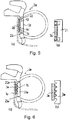
- the embodiment shown for a door seal has a strand 2d a recess 4d for receiving an adhesive material layer 3d. Areas 13 and 14 for receiving excess adhesive material are provided in the recess 4d. Such areas can advantageously compensate for fluctuations in the amount of adhesive material supplied, in particular during application of the strand 2d as an endless strand.
- a section 21 of the strand 2d having the recess 4d with the regions 13, 14 is connected to the rest of the strand via weak points 22 and 23.
- a strand 2e in an adhesive surface facing a flange 1e has a plurality of receiving grooves 15 for excess adhesive material of an adhesive material layer 3e formed between the adhesive surface and the strand 2e.
- a section 21e of the strand 2e having the receiving grooves 15 is connected to the rest of the strand via weak points 22e and 23e. When the strand is pulled off, an assembly seat formed by the adhesive layer 3e and the section 21e remains.
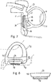
- FIG. 7 The exemplary embodiment shown of a further door seal comprises an adhesive material layer 3f which connects a section 16 of a strand 2f to a body flange 1f.
- the section 16 is separated from the rest of the strand 2f by a cavity 19 and is only connected to the rest of the strand 2f via weak points 17 and 18.
- the strand 2f can be pulled off without any problems, destroying the weak points 17, 18, leaving an assembly seat formed by the section 16 and the adhesive material layer 3e for a spare part strand.
- the string of spare parts can have a recess corresponding to the assembly seat.
- Fig. 8 shows a seal with a strand 2g which is glued to a vehicle door 1g on a lip 24 via an adhesive material layer 3g.
- the lip 24 has a predetermined breaking point at 25.
Landscapes
- Engineering & Computer Science (AREA)
- Mechanical Engineering (AREA)
- Civil Engineering (AREA)
- Structural Engineering (AREA)
- Seal Device For Vehicle (AREA)
Description
- Die Erfindung betrifft eine Zusammenstellung umfassend eine Fahrzeugkarosserie, eine an einer Tür- oder Öffnungsklappe der Fahrzeugkarosserie umlaufende Dichtung oder/und Abdeckung mit einem ein Elastomermaterial aufweisenden flexiblen Strang und eine sich in Stranglängsrichtung erstreckende, den Strang mit der Fahrzeugkarosserie verbindende Klebermaterialschicht.
- Bekanntermaßen wird im Fertigungsprozess zur Verbindung extrudierter Dichtungsstränge mit Fahrzeugkarosserien doppelt klebendes Klebeband eingesetzt, wie dies z.B. aus der
US 2007/0245634 A1 bekannt ist. Die Verbindung wird also über zwei Kleberschichten hergestellt. - Eine Dichtung der eingangs genannten Art mit einer einzigen Klebermaterialschicht geht aus der
WO 02/076 778 A1 EP 1 419 919 A bekannt. - Der Erfindung liegt die Aufgabe zugrunde, eine neue, effizient applizierbare und reparaturfreundliche Dichtung der eingangs erwähnten Art zu schaffen.
- Die diese Aufgabe lösende Zusammenstellung nach der Erfindung ist durch die Merkmale von Anspruch 1 gekennzeichnet.
- Erßfindungsgemäß bleibt im Reparaturfall beim Abziehen des ggf. beschädigten Dichtungsstrangs eine saubere, von Abrissresten weitgehend freie und ohne aufwendige Nachbearbeitung unmittelbar mit einem Ersatzteilstrang verbindbare Klebefläche zurück.
- Der Strang ist unter Zurücklassung einer solchen Klebefläche von der kompletten Klebermaterialschicht oder zusammen mit der Klebermaterialschicht von der Karosserie abziehbar. Zum Beispiel haftet im ersteren Fall das Klebermaterial der Klebermaterialschicht als solches stärker am Lack der Karosserie als an dem Elastomermaterial des Strangs an, im zweiten Fall ist umgekehrt die Klebeverbindung zwischen dem Elastomermaterial des Strangs und der Klebermaterialschicht fester als zwischen der Klebermaterialschicht und dem Karosserielack.
- In einer nicht erfindungsgemäßen Variante kann sich der Strang beim Abziehen zusammen mit einem Teil der Klebermaterialschicht von einem auf der Karosserie verbleibenden Teil der Klebermaterialschicht lösen. In diesem Fall übertrifft die Haftfestigkeit des Klebermaterials sowohl am Elastomermaterial des Strangs als auch am Lack der Karosserie die Zerreißfestigkeit der Klebermaterialschicht als solcher.
- In einer weiteren Ausführungsform der Erfindung ist die Klebermaterialschicht mit dem Strang oder der Karosserie über eine Trennschicht verbunden, welche die Ablösung an den betreffenden Schichtgrenzen erleichtert.
- Vorzugsweise haftet die Trennschicht an der Klebermaterialschicht stärker als an dem Strang oder der Karosserie an. So bleibt beim Abziehen des Strangs entweder die Trennschicht mit der Klebermaterialschicht zurück oder die gesamte Dichtung einschließlich der Klebermaterial- und Trennschicht wird unter Freilegung des Karosserielacks entfernt.
- Alternativ kann der Strang beim Abziehen zusammen mit der Trennschicht von der Klebermaterialschicht oder zusammen mit einem Teil der Trennschicht von einem auf der Klebermaterialschicht verbleibenden Teil des Trennschicht lösbar sein.
- Vorzugsweise ist die Trennschicht mit dem Strang vorgefertigt, insbesondere mitextrudiert.
- Die Trennschicht kann eine die Haftung der Klebermaterialschicht am Elastomermaterial oder Karosserielack, insbesondere dessen Benetzung durch das Klebermaterial herabsetzen. Alternativ ist sie aus einem Material, z.B. geschäumtem Elastomermaterial, gebildet, dessen Zerreißfestigkeit so gering ist, dass die Trennschicht als solche zerreißt und eine Sollbruchstelle bildet.
- Insbesondere kann die Trennschicht ein Textilmaterial oder perforiertes Folienmaterial aufweisen.
- Für den Fall, dass die Trennschicht, entsprechend einer weiteren Ausführungsform, an Schwachstellen von dem übrigen Strang lösbar ist, kann die Trennschicht aus demselben Elastomermaterial wie der übrige Strang bestehen.
- In weiterer Ausgestaltung der Erfindung kann der Strang eine die Klebermaterial- oder/und Trennschicht wenigstens teilweise aufnehmende, zur Karosserie hin offene Ausnehmung aufweisen.
- Insbesondere in einer solchen Ausführungsform kann die ausgehärtete Klebermaterialschicht oder/und Trennschicht einen Montagesitz für den als Ersatzteil zu montierenden Strang bilden, der die passgenaue Anordnung des Ersatzteilstrangs wesentlich erleichtert.
- In weiterer Ausgestaltung der Erfindung weist der Strang eine oder mehrere Ausnehmungen für die Aufnahme überschüssigen Klebermaterials auf. Hierbei kann es sich insbesondere um Längs- oder Querrillen handeln. Die Ausnehmung für die Aufnahme überschüssigen Klebermaterials kann auch durch eine Erweiterung der weiter oben erwähnten Ausnehmung gebildet sein.
- Zur Bildung der Klebermaterialschicht ist zweckmäßig ein pastöser Kleberstoff vorgesehen, der im Dichtungssitz vorhandene Unebenheiten, wie Vertiefungen an Schweißpunkten oder Absätze an Überlappungsstellen des Karosseriebleches ausgleichen kann.
- Als pastöse Klebestoffe kommen vor allem reaktive heißschmelzende Klebestoffe in Betracht.
- Alternativ ließe sich das Klebermaterial durch eine thermoplastische Folie bilden, die erst durch Erwärmung klebfähig gemacht wird.
- In einer besonders bevorzugten Ausführungsform ist dieses thermoplastische Folienmaterial mehrlagig mit beim Abziehen des Strangs voneinander trennbaren Lagen ausgebildet. Auch das thermoplastische Folienmaterial lässt sich mit dem Strang vorfertigen, insbesondere mitextrudieren.
- Die Erfindung wird nachfolgend anhand von Ausführungsbeispielen und der beiliegenden, sich auf diese Ausführungsbeispiele beziehenden Zeichnungen weiter erläutert. Es zeigen:
- Fig. 1 und 2
- Querschnittsdarstellungen von Ausführungsbeispielen für erfindungsgemäße Dichtungen mit einer Klebermaterialschicht, die einen Montagesitz zur Aufnahme eines Ersatzteilstrangs bildet,
- Fig. 3 und 4
- Ausführungsbeispiele für erfindungsgemäße Dichtungen mit einer Trennschicht zwischen einem Strang und einer Klebermaterialschicht im Querschnitt,
- Fig.5 und 6
- Ausführungsbeispiele für erfindungsgemäße Dichtungen mit Aufnahmebereichen für überschüssiges Klebermaterial und mit Schwachstellen im Querschnitt, und
- Fig. 7 und 8
- Querschnittsdarstellungen von Ausführungsbeispielen für erfindungsgemäße Dichtungen mit an Schwachstellen von einem Strang lösbaren Trennschichten.
- Eine in
Fig. 1 gezeigte Dichtung an einer Fahrzeugtür ist mit einem am Türöffnungsrand umlaufenden Karosserieflansch 1 verbunden. Die Türdichtung umfasst einen extrudierten Strang 2 aus Elastomermaterial und eine den Strang 2 mit dem Flansch 1 unmittelbar verbindende Klebermaterialschicht 3. Die Klebermaterialschicht 3 befindet sich innerhalb einer zum Flansch 1 hin offenen, im Strang 2 vorgesehenen Ausnehmung 4. Ein schlauchförmiger Dichtungsabschnitt 5 des Strangs 2 liegt bei geschlossener Fahrzeugtür gegen eine bei 6 angedeutete, am Rand der Fahrzeugtür umlaufende weitere Dichtung an. Der Strang 2 umfasst ferner einen U-förmigen Abschnitt 7, in den eine Fahrzeuginnenverkleidung 8 mit ihrem Rand eingreift. Eine Dichtzunge 9 des Strangs 9 liegt angrenzend an den Flansch 1 gegen die Fahrzeugkarosserie an. - In dem gezeigten Ausführungsbeispiel wurde der Strang 2 als Endlosstrang fortlaufend auf den Karosserieflansch 1 aufgerollt und entsprechend der Umfangslänge der Dichtung abgetrennt, wobei dem zugeführten Strang vor der Klebeverbindung mit dem Flansch 1 laufend unter Auffüllung der Ausnehmung 4 die Klebermaterialschicht 3 bildendes Klebermaterial zugeleitet wurde. Alternativ könnte das Klebermaterial schon beim Herstellen des Strangs appliziert und die gefüllte Ausnehmung 4 durch einen vor dem Aufrollen des Strangs auf den Flansch zu entfernenden Folienstreifen abgedeckt werden. Die zweite Alternative kommt vor allem in Betracht, wenn die Aushärtung des Klebermaterials erst nach der Applikation des Strangs auf den Flansch, z.B. durch Wärmezuführung, eingeleitet wird.
- Das verwendete Klebermaterial der Klebermaterialschicht 3 haftet am Lack der Karosserie stärker an als am Elastomermaterial des Strangs 2. Der Strang 2 lässt sich dadurch z.B. im Falle einer notwendigen Reparatur problemlos gegen einen Ersatzteilstrang auswechseln, indem beim Abziehen des Strangs 2 von der ausgehärteten Klebermaterialschicht 3 ein sauberer, von abgerissenen Elastomermaterialresten freier Montagesitz 10 für den Ersatzteilstrang zurück bleibt (
Fig. 1b ). Der durch das ausgehärtete Klebermaterial der Klebermaterialschicht 3 gebildete Montagesitz 10, der in eine der Ausnehmung 4 entsprechende Ausnehmung im Ersatzteilstrang eingreift, erleichtert erheblich die positionsgenaue Anbringung des Ersatzteilstrangs am Fahrzeug. Die saubere, rückstandsfreie Oberfläche des Montagesitzes ermöglicht ohne aufwendige Nachbearbeitung eine Verklebung mit dem Ersatzteilstrang. - In den nachfolgenden Figuren sind gleiche oder gleichwirkende Teile mit derselben Bezugszahl wie in
Fig. 1 bezeichnet, wobei der betreffenden Bezugszahl der Buchstabe a, b usw. beigefügt ist. - Wie
Fig. 2 erkennen lässt, könnte ein durch eine ausgehärtete Klebermaterialschicht 3a gebildeter Montagesitz Hinterschneidungen 12 aufweisen, so dass ein Ersatzteilstrang mit einer Ausnehmung, welche der die Klebermaterialschicht 3a aufnehmenden Ausnehmung 4a des gezeigten Strangs 2a entspricht, an dem Montagesitz einrasten könnte. Ein solcher Montagesitz ließe sich auch durch eine Trennschicht gemäßFig. 4 bilden. - Ein in
Fig. 3 gezeigtes Ausführungsbeispiel für eine Türdichtung umfasst eine Klebermaterialschicht 3b, die sich im Unterschied zu den Ausführungsbeispielen vonFig. 1 und 2 außerhalb einer im Strang 2b gebildeten Ausnehmung 4b befindet. Die Ausnehmung 4b selbst ist mit einer Trennschicht 11 ausgefüllt. - Die Haftung des Strangs 2b an der Trennschicht 11 ist schwächer als die Haftung der Trennschicht 11 an der Klebermaterialschicht 3b und auch schwächer als die Haftung der Klebermaterialschicht 3b am Karosserieflansch 1b. Der Strang 2b lässt sich daher im Reparaturfall problemlos von der Trennschicht 11 abziehen, und es entsteht, wie bei den Ausführungsbeispielen von
Fig. 1 und3 , ein Montagesitz mit einer sauberen, unmittelbar zur Verklebung mit einem Ersatzteilstrang geeigneten Oberfläche. - Zweckmäßig ist die Trennschicht 11 bei der Herstellung des Stranges 2b mit dem Strang 2b mitextrudiert.
- Gemäß
Fig. 4 ist eine im Vergleich zu der Trennschicht 11 dünnere Trennschicht 11c gebildet, die am Elastomermaterial eines Strangs 2c fester anhaftet als die Trennschicht 11 an dem Strang 2b. Die Trennschicht 11c weist eine geringe Zerreißfestigkeit auf, so dass sie beim Abziehen des Strangs 2c in sich reißt, wobei sie eine zur Verklebung mit einem Ersatzteilstrang ausreichend glatte Bruchfläche 20 bildet (Fig. 4b ). Die mit dem Strang 2c mitextrudierte Trennschicht 11c besteht in dem gezeigten Ausführungsbeispiel aus einem geschäumten Elastomermaterial, z.B. Moosgummi. - Bei einem in
Fig. 5 gezeigten Ausführungsbeispiel für eine Türdichtung weist ein Strang 2d eine Ausnehmung 4d für die Aufnahme einer Klebermaterialschicht 3d auf. In der Ausnehmung 4d sind Bereiche 13 und 14 für die Aufnahme überschüssigen Klebermaterials vorgesehen. Vorteilhaft können durch solche Bereiche Schwankungen der Zufuhrmenge des Klebermaterials, insbesondere während einer Applikation des Strangs 2d als Endlosstrang, ausgeglichen werden. Ein die Ausnehmung 4d mit den Bereichen 13,14 aufweisender Abschnitt 21 des Strangs 2d ist mit dem übrigen Strang über Schwachstellen 22 und 23 verbunden. - Beim Abziehen des Strangs reißt der Strang an den Schwachstellen und es verbleibt ein durch die ausgehärtete Klebermaterialschicht 3d und den Abschnitt 21 gebildeter Montagesitz 10d (
Fig. 5b ). - Bei einem in
Fig. 6 gezeigten Ausführungsbeispiel weist ein Strang 2e in einer einem Flansch 1e zugewandten Klebefläche mehrere Aufnahmerillen 15 für überschüssiges Klebermaterial einer zwischen der Klebefläche und dem Strang 2e gebildeten Klebermaterialschicht 3e auf. Ein die Aufnahmerillen 15 aufweisender Abschnitt 21e des Strangs 2e ist über Schwachstellen 22e und 23e mit dem übrigen Strang verbunden. Beim Abziehen des Strangs verbleibt ein durch die Kleberschicht 3e und den Abschnitt 21e gebildeter Montagesitz. - Ein in
Fig. 7 gezeigtes Ausführungsbeispiel einer weiteren Türdichtung umfasst eine Klebermaterialschicht 3f, die einen Abschnitt 16 eines Strangs 2f mit einem Karosserieflansch 1f verbindet. Der Abschnitt 16 ist durch einen Hohlraum 19 vom übrigen Strang 2f abgetrennt und nur über Schwachstellen 17 und 18 mit dem übrigen Strang 2f verbunden. - Im Reparaturfall lässt sich der Strang 2f problemlos unter Zerstörung der Schwachstellen 17,18 abziehen, wobei ein durch den Abschnitt 16 und die Klebermaterialschicht 3e gebildeter Montagesitz für einen Ersatzteilstrang zurück bleibt. Der Ersatzteilstrang kann eine dem Montagesitz entsprechende Ausnehmung aufweisen.
-
Fig. 8 zeigt eine Dichtung mit einem Strang 2g, der an einer Lippe 24 über eine Klebermaterialschicht 3g mit einer Fahrzeugtür 1g verklebt ist. Die Lippe 24 weist bei 25 eine Sollbruchstelle auf. - Beim Abziehen des Strangs 2g reißt der Strang an der Sollbruchstelle 25. Zurück bleibt ein durch die Klebermaterialschicht 3d und einen abgetrennten Abschnitt 26 des Strangs 2g gebildeter Montagesitz.
Claims (15)
- Zusammenstellung umfassend eine Fahrzeugkarosserie (1), eine an einer Tür- oder Öffnungsklappe der Fahrzeugkarosserie (1) umlaufende Dichtung oder/und Abdeckung mit einem ein Elastomermaterial aufweisenden flexiblen Strang (2) und eine sich in Stranglängsrichtung erstreckende, den Strang (2) mit der Fahrzeugkarosserie (1) verbindende Klebermaterialschicht (3),
dadurch gekennzeichnet,
dass die Zerreißfestigkeit der Klebermaterialschicht (3) die Haftfestigkeit des Klebermaterials am Elastomermaterial des Strangs und/oder die Haftfestigkeit des Klebermaterials an einem Lack der Karosserie übertrifft, so dass der Strang (2) unter Hinterlassen einer von Abrissresten freien Klebefläche von der kompletten Klebermaterialschicht (3) oder zusammen mit der Klebermaterialschicht (3) von der Karosserie abziehbar ist, zwecks Verklebung der Karosserie (1) mit einem Ersatzteilstrang. - Zusammenstellung nach Anspruch 1,
dadurch gekennzeichnet,
dass der Strang (2) von der kompletten Klebermaterialschicht (3) oder zusammen mit der kompletten Klebermaterialschicht (3) von der Karosserie (1) oder zusammen mit einem Teil der Klebermaterialschicht von einem auf der Karosserie verbleibenden Teil der Klebermaterialschicht abziehbar ist. - Zusammenstellung nach Anspruch 1 oder 2,
dadurch gekennzeichnet,
dass das Klebermaterial der Klebermaterialschicht (3) stärker an dem Elastomermaterial des Strangs (2) als am Lack der Karosserie oder umgekehrt das Klebermaterial stärker am Lack der Karosserie (1) als am Elastomermaterial des Strangs (2) anhaftet. - Zusammenstellung nach einem der Ansprüche 1 bis 3,
dadurch gekennzeichnet,
dass die Klebermaterialschicht (3) mit dem Strang (2) oder der Karosserie über eine Trennschicht (11;16;21;24) verbunden ist. - Zusammenstellung nach Anspruch 4,
dadurch gekennzeichnet,
dass die Trennschicht (11;16;21;24) mit dem Strang (2)vorgefertigt ist, insbesondere mitextrudiert ist. - Zusammenstellung nach Anspruch 4 oder 5,
dadurch gekennzeichnet,
dass der Strang (2) zusammen mit der Trennschicht (11) von der Klebermaterialschicht, zusammen mit einem Teil der Trennschicht (11c) von einem auf der Klebermaterialschicht (3c) verbleibenden Teil der Trennschicht (11c) oder von der gesamten, auf der Klebermaterialschicht (3) verbleibenden Trennschicht (11;16;21;24) abziehbar ist. - Zusammenstellung nach einem der Ansprüche 4 bis 6,
dadurch gekennzeichnet,
dass die Trennschicht die Haftung des Strangs (2) oder der Karosserie (1) an der Klebermaterialschicht herabsetzt oder/und aus einem Material geringer Zerreißfestigkeit besteht, durch das eine Sollbruchstelle gebildet ist. - Zusammenstellung nach einem der Ansprüche 4 bis 7,
dadurch gekennzeichnet,
dass die Trennschicht (11) den Benetzungsgrad des Strangs (2) oder der Karosserie (1) durch das Klebermaterial der Klebermaterialschicht herabsetzt. - Zusammenstellung nach einem der Ansprüche 4 bis 8,
dadurch gekennzeichnet,
dass die Trennschicht (16; 21; 24) über Sollbruchstellen (17,18; 22,23; 25) mit dem übrigen Strang (2) verbunden ist. - Zusammenstellung nach einem der Ansprüche 1 bis 9.
dadurch gekennzeichnet,
dass der Strang (2) eine die Klebermaterial- oder/und Trennschicht (11) wenigstens teilweise aufnehmende Ausnehmung (4) aufweist. - Zusammenstellung nach Anspruch 10,
dadurch gekennzeichnet,
dass durch die ausgehärtete Klebermaterialschicht (3) oder /und Trennschicht (11;16;21;24) ein Montagesitz (10) für den Ersatzteilstrang gebildet ist. - Zusammenstellung nach einem der Ansprüche 1 bis 11,
dadurch gekennzeichnet,
dass der Strang (2) eine Ausnehmung (13,14; 15) für die Aufnahme überschüssigen Klebermaterials aufweist. - Zusammenstellung nach einem der Ansprüche 1 bis 12,
dadurch gekennzeichnet,
dass zur Bildung der Klebermaterialschicht (3) ein pastöser Klebestoff, ein Hotmelt-Klebstoff, ein Klebstoff auf PU-Basis oder ein thermoplastisches Folienmaterial vorgesehen ist. - Zusammenstellung nach Anspruch 13,
dadurch gekennzeichnet,
dass das thermoplastische Folienmaterial mehrlagig mit beim Abziehen des Strangs (2) voneinander trennbaren Lagen ausgebildet ist. - Zusammenstellung nach Anspruch 13 oder 14,
dadurch gekennzeichnet,
dass das thermoplastische Folienmaterial mit dem Strang vorgefertigt, insbesondere mitextrudiert, ist.
Applications Claiming Priority (2)
| Application Number | Priority Date | Filing Date | Title |
|---|---|---|---|
| DE102012100300 | 2012-01-13 | ||
| PCT/DE2013/100007 WO2013104358A1 (de) | 2012-01-13 | 2013-01-11 | Kfz-dichtung |
Publications (2)
| Publication Number | Publication Date |
|---|---|
| EP2802472A1 EP2802472A1 (de) | 2014-11-19 |
| EP2802472B1 true EP2802472B1 (de) | 2021-03-03 |
Family
ID=47845677
Family Applications (1)
| Application Number | Title | Priority Date | Filing Date |
|---|---|---|---|
| EP13708659.1A Active EP2802472B1 (de) | 2012-01-13 | 2013-01-11 | Kfz-dichtung |
Country Status (6)
| Country | Link |
|---|---|
| US (1) | US20140352225A1 (de) |
| EP (1) | EP2802472B1 (de) |
| CN (1) | CN104039573A (de) |
| DE (1) | DE102013100276A1 (de) |
| ES (1) | ES2863748T3 (de) |
| WO (1) | WO2013104358A1 (de) |
Families Citing this family (7)
| Publication number | Priority date | Publication date | Assignee | Title |
|---|---|---|---|---|
| DE102014110541A1 (de) * | 2014-07-25 | 2016-01-28 | Cqlt Saargummi Technologies S.À.R.L. | Dichtungsstrang und Verfahren zu seiner Herstellung |
| WO2016172483A1 (en) * | 2015-04-24 | 2016-10-27 | Quick Fix Solutions, Inc. | Sealing device and method of installation |
| CN105299227B (zh) * | 2015-11-20 | 2018-08-03 | 苏州国泰科技发展有限公司 | 一种塑胶密封件 |
| CN106494196A (zh) * | 2016-12-13 | 2017-03-15 | 桐乡市乌镇润桐嘉业机械维修中心 | 一种汽车导槽密封条 |
| KR102359944B1 (ko) | 2017-09-22 | 2022-02-07 | 현대자동차 주식회사 | 웨더스트립의 부착 시스템 및 부착 방법 |
| DE112019000452A5 (de) * | 2018-01-19 | 2020-12-10 | ATN Hölzel GmbH | Verfahren und vorrichtung zur lageerkennung einer dichtung |
| DE102022115292A1 (de) | 2022-06-20 | 2023-12-21 | Cqlt Saargummi Technologies S.À.R.L. | Dichtungsprofil, Verfahren zur Herstellung eines Dichtungsprofils und Montageverfahren |
Family Cites Families (30)
| Publication number | Priority date | Publication date | Assignee | Title |
|---|---|---|---|---|
| US4308302A (en) * | 1981-02-27 | 1981-12-29 | The Goodyear Tire & Rubber Company | Weatherstrip and composition of matter therefor |
| US4925714A (en) * | 1985-02-05 | 1990-05-15 | Avery International Corporation | Coextruded core laminates |
| DE3504907A1 (de) * | 1985-02-13 | 1986-08-14 | Continental Gummi-Werke Ag, 3000 Hannover | Elastomer-profilleiste zum dichtenden einfassen von fensterscheiben |
| DE3722657C1 (de) * | 1987-07-09 | 1989-02-09 | Ver Glaswerke Gmbh | Verfahren zum Herstellen einer Ioesbaren Direktverklebung fuer eine Autoglasscheibe |
| FR2667672B1 (fr) * | 1990-10-04 | 1993-08-13 | Hutchinson | Joint profile a base d'elastomere, matiere plastique ou analogue, procede de fabrication d'un tel joint et son procede de montage. |
| DE59206897D1 (de) * | 1991-07-03 | 1996-09-19 | Gurit Essex Ag | Lösbare Klebeverbindungen, Verfahren zu deren Herstellung und Verwendung von Vorrichtungen zum Lösen solcher Klebeverbindungen |
| US5449544A (en) * | 1992-06-06 | 1995-09-12 | Toyoda Gosei Co., Ltd. | Weather strip for an automobile and a method for assembling the same |
| US5620794A (en) * | 1992-07-01 | 1997-04-15 | Gurit-Essex Ag | Releasable adhesive joint, a method for establishing a releasable adhesive joint and an apparatus for releasing such adhesive joints |
| US5423147A (en) * | 1994-02-17 | 1995-06-13 | Gencorp Inc. | Wireless carrier weatherstrip seal |
| DE4441852A1 (de) * | 1994-11-24 | 1996-05-30 | Bayerische Motoren Werke Ag | An einem Tragteil vorgesehene gummielastische Profilleiste |
| JP3191602B2 (ja) * | 1995-02-13 | 2001-07-23 | 豊田合成株式会社 | 自動車用ウエザストリップ |
| ES2152060T3 (es) * | 1996-08-22 | 2001-01-16 | Volkswagen Ag | Fijacion de una luna de ventanilla en un vehiculo motorizado. |
| US6004642A (en) * | 1996-11-08 | 1999-12-21 | 3M Innovative Properties Company | Internally separable tape laminate |
| DE19802203A1 (de) * | 1998-01-22 | 1999-08-05 | Henniges Elastomer Kunststoff | Verfahren zum Herstellen einer Verbindung eines Bauteils mit einem Bauelement |
| DE19837143C2 (de) * | 1998-08-17 | 2001-03-29 | Beiersdorf Ag | Einseitig selbstklebendes, wärmeaktivierbares Klebeband und seine Verwendung |
| DE10043136B4 (de) * | 2000-08-31 | 2013-08-01 | Webasto Ag | Dichtungsprofil, insbesondere für eine Schiebedachdichtung |
| DE10142288B4 (de) | 2001-03-27 | 2006-04-20 | Saargummi Gmbh | Trägerprofil und Verbindungsbereich für Dichtungsprofile an Automobilkarosserien |
| DE10214337A1 (de) * | 2002-03-28 | 2003-10-16 | Kreye Bernhard | Verfahren zum Herstellen einer Aufklippbefestigungsanordnung |
| DE50302500D1 (de) * | 2002-06-26 | 2006-04-27 | Webasto Ag Fahrzeugtechnik | Klebeband zur Befestigung eines Dichtungselementes, und Verfahren zur Herstellung und zur Befestigung des Dichtungselementes |
| DE10252595B3 (de) * | 2002-11-12 | 2004-05-06 | Metzeler Automotive Profile Systems Gmbh | Dichtung, insbesondere zum Abdichten einer Tür, einer Fensterscheibe oder des Dachs eines Kraftfahrzeugs |
| DE10254096B3 (de) * | 2002-11-20 | 2004-03-18 | Daimlerchrysler Ag | Klebstoffverbund für eine wieder lösbare Verbindung |
| GB2397609B (en) * | 2003-01-23 | 2006-05-17 | Gdx Automotive Rehburg Gmbh & | Panel-shaped members with strips joined to them, and associated methods |
| ITVR20040049A1 (it) * | 2004-04-02 | 2004-07-02 | Gianfranco Natali | Elemento di protezione per cassoni di veicoli indstriali |
| JP4529818B2 (ja) * | 2005-06-30 | 2010-08-25 | 豊田合成株式会社 | 自動車用ウエザストリップ |
| US20070245634A1 (en) * | 2006-03-23 | 2007-10-25 | Toyoda Gosei Co., Ltd. | Weather strip |
| EP1845229B1 (de) * | 2006-04-13 | 2012-11-14 | Dätwyler Ag Schweizerische Kabel-, Gummi- Und Kunststoffwerke | Verglasungsdichtung |
| JP2008087495A (ja) * | 2006-09-29 | 2008-04-17 | Toyoda Gosei Co Ltd | 自動車用ウエザストリップ |
| EP2062926A1 (de) * | 2007-11-21 | 2009-05-27 | Sika Technology AG | Polyurethanpolymer für reversible Klebeverbindungen |
| CN201164235Y (zh) * | 2008-03-27 | 2008-12-17 | 黄首征 | 婴幼儿安全防护装置 |
| CN102107637A (zh) * | 2009-12-23 | 2011-06-29 | 上海工商信息学校 | 车体防御罩 |
-
2013
- 2013-01-11 ES ES13708659T patent/ES2863748T3/es active Active
- 2013-01-11 CN CN201380005219.4A patent/CN104039573A/zh active Pending
- 2013-01-11 US US14/371,116 patent/US20140352225A1/en not_active Abandoned
- 2013-01-11 EP EP13708659.1A patent/EP2802472B1/de active Active
- 2013-01-11 WO PCT/DE2013/100007 patent/WO2013104358A1/de not_active Ceased
- 2013-01-11 DE DE102013100276A patent/DE102013100276A1/de active Pending
Non-Patent Citations (1)
| Title |
|---|
| None * |
Also Published As
| Publication number | Publication date |
|---|---|
| US20140352225A1 (en) | 2014-12-04 |
| ES2863748T3 (es) | 2021-10-11 |
| DE102013100276A1 (de) | 2013-07-18 |
| WO2013104358A1 (de) | 2013-07-18 |
| EP2802472A1 (de) | 2014-11-19 |
| CN104039573A (zh) | 2014-09-10 |
Similar Documents
| Publication | Publication Date | Title |
|---|---|---|
| WO2013104358A1 (de) | Kfz-dichtung | |
| DE68911385T2 (de) | Vorbereitungsverfahren für Direktfahrzeugsverglasung. | |
| DE102013014405B4 (de) | Verkleidungsteil zur Anbringung an einem Fahrzeug-Karosserieteil mit einem Airbag-Modul, Airbagsystem mit einem Karosserieteil und einem solchen Verkleidungsteil und Verfahren zur Herstellung des Verkleidungsteils | |
| DE3486392T2 (de) | Klebemontage von Scheiben in eine Öffung, insbesondere von Windschutzscheiben für Kraftfahrzeuge, zur erleichterten Demontage. | |
| DE3500205A1 (de) | Klebeverbindung fuer die verklebung einer glasscheibe mit einem fensterrahmen | |
| EP3110647A1 (de) | Mehrkammerbehälter | |
| DE102004003190A1 (de) | Baugruppe einer Kraftfahrzeugkarosserie in Schalenbauweise | |
| DE102014114414A1 (de) | Rahmenkonstruktion für eine Glasscheibe und Verfahren zu deren Herstellung | |
| EP0825052B1 (de) | Befestigung einer Fensterscheibe in einem Kraftfahrzeug | |
| DE19602245A1 (de) | Karosserieteil mit anextrudierter Dichtung | |
| DE102010042186A1 (de) | Verbund, Luft- oder Raumfahrzeug sowie Verfahren | |
| DE102018002408A1 (de) | Fahrzeugdachdeckel mit einem Rahmenteil | |
| DE10312465B4 (de) | Verfahren zur Herstellung eines Fahrzeug-Karosserieteils | |
| EP1858720B1 (de) | Dichtungsanordnung | |
| EP1946951B1 (de) | Verfahren zur Herstellung einer Dichtung, insbesondere für ein Kraftfahrzeug, und eine solche Dichtung | |
| EP3085563A1 (de) | Spritzgegossene wasserablaufleiste und anordnung für eine fahrzeugverkleidung | |
| EP3359304B1 (de) | Automatisiertes primerauftragssystem | |
| EP1767327B1 (de) | Verfahren zur Herstellung eines Innenverkleidungsteils mit einer zweiteiligen Haut und Innenverkleidungsteil hergestellt nach dem Verfahren | |
| EP1488112A1 (de) | Verfahren zum herstellen einer aufklippbefestigungsanordung sowie aufklippbefestigungsanordnung | |
| EP3587084B1 (de) | Verfahren zum herstellen eines kunststoffbauteils | |
| DE102005043517B4 (de) | Anbindung von als Verdeckstoff ausgeführten Abdeckmitteln | |
| EP2089595B1 (de) | Dichtungsband, Verfahren zur Herstellung eines solchen Dichtungsbandes sowie dessen Verwendung | |
| DE102017202865B3 (de) | Verfahren und Vorrichtung zum Verbinden von zwei Dichtungsenden in einem Stoßbereich | |
| EP1199226A2 (de) | Herstellverfahren für ein Fahrzeug-Innenausstattungsteil mit einer Airbag-Aufreissnaht | |
| DE102015210447B4 (de) | Dichtungsanordnung für ein Spiegeldreieck einer Kraftwagenseitentür |
Legal Events
| Date | Code | Title | Description |
|---|---|---|---|
| PUAI | Public reference made under article 153(3) epc to a published international application that has entered the european phase |
Free format text: ORIGINAL CODE: 0009012 |
|
| 17P | Request for examination filed |
Effective date: 20140806 |
|
| AK | Designated contracting states |
Kind code of ref document: A1 Designated state(s): AL AT BE BG CH CY CZ DE DK EE ES FI FR GB GR HR HU IE IS IT LI LT LU LV MC MK MT NL NO PL PT RO RS SE SI SK SM TR |
|
| DAX | Request for extension of the european patent (deleted) | ||
| STAA | Information on the status of an ep patent application or granted ep patent |
Free format text: STATUS: EXAMINATION IS IN PROGRESS |
|
| 17Q | First examination report despatched |
Effective date: 20170313 |
|
| REG | Reference to a national code |
Ref country code: DE Ref legal event code: R079 Ref document number: 502013015531 Country of ref document: DE Free format text: PREVIOUS MAIN CLASS: B60J0010080000 Ipc: B60J0010340000 |
|
| GRAP | Despatch of communication of intention to grant a patent |
Free format text: ORIGINAL CODE: EPIDOSNIGR1 |
|
| STAA | Information on the status of an ep patent application or granted ep patent |
Free format text: STATUS: GRANT OF PATENT IS INTENDED |
|
| RIC1 | Information provided on ipc code assigned before grant |
Ipc: B60J 10/34 20160101AFI20200909BHEP Ipc: B60J 10/35 20160101ALI20200909BHEP Ipc: B60J 10/80 20160101ALI20200909BHEP |
|
| INTG | Intention to grant announced |
Effective date: 20201002 |
|
| GRAS | Grant fee paid |
Free format text: ORIGINAL CODE: EPIDOSNIGR3 |
|
| GRAA | (expected) grant |
Free format text: ORIGINAL CODE: 0009210 |
|
| STAA | Information on the status of an ep patent application or granted ep patent |
Free format text: STATUS: THE PATENT HAS BEEN GRANTED |
|
| AK | Designated contracting states |
Kind code of ref document: B1 Designated state(s): AL AT BE BG CH CY CZ DE DK EE ES FI FR GB GR HR HU IE IS IT LI LT LU LV MC MK MT NL NO PL PT RO RS SE SI SK SM TR |
|
| REG | Reference to a national code |
Ref country code: GB Ref legal event code: FG4D Free format text: NOT ENGLISH |
|
| REG | Reference to a national code |
Ref country code: AT Ref legal event code: REF Ref document number: 1366825 Country of ref document: AT Kind code of ref document: T Effective date: 20210315 Ref country code: CH Ref legal event code: EP |
|
| REG | Reference to a national code |
Ref country code: DE Ref legal event code: R096 Ref document number: 502013015531 Country of ref document: DE |
|
| REG | Reference to a national code |
Ref country code: IE Ref legal event code: FG4D Free format text: LANGUAGE OF EP DOCUMENT: GERMAN |
|
| REG | Reference to a national code |
Ref country code: LT Ref legal event code: MG9D |
|
| PG25 | Lapsed in a contracting state [announced via postgrant information from national office to epo] |
Ref country code: LT Free format text: LAPSE BECAUSE OF FAILURE TO SUBMIT A TRANSLATION OF THE DESCRIPTION OR TO PAY THE FEE WITHIN THE PRESCRIBED TIME-LIMIT Effective date: 20210303 Ref country code: FI Free format text: LAPSE BECAUSE OF FAILURE TO SUBMIT A TRANSLATION OF THE DESCRIPTION OR TO PAY THE FEE WITHIN THE PRESCRIBED TIME-LIMIT Effective date: 20210303 Ref country code: HR Free format text: LAPSE BECAUSE OF FAILURE TO SUBMIT A TRANSLATION OF THE DESCRIPTION OR TO PAY THE FEE WITHIN THE PRESCRIBED TIME-LIMIT Effective date: 20210303 Ref country code: GR Free format text: LAPSE BECAUSE OF FAILURE TO SUBMIT A TRANSLATION OF THE DESCRIPTION OR TO PAY THE FEE WITHIN THE PRESCRIBED TIME-LIMIT Effective date: 20210604 Ref country code: BG Free format text: LAPSE BECAUSE OF FAILURE TO SUBMIT A TRANSLATION OF THE DESCRIPTION OR TO PAY THE FEE WITHIN THE PRESCRIBED TIME-LIMIT Effective date: 20210603 Ref country code: NO Free format text: LAPSE BECAUSE OF FAILURE TO SUBMIT A TRANSLATION OF THE DESCRIPTION OR TO PAY THE FEE WITHIN THE PRESCRIBED TIME-LIMIT Effective date: 20210603 |
|
| REG | Reference to a national code |
Ref country code: NL Ref legal event code: MP Effective date: 20210303 |
|
| PG25 | Lapsed in a contracting state [announced via postgrant information from national office to epo] |
Ref country code: SE Free format text: LAPSE BECAUSE OF FAILURE TO SUBMIT A TRANSLATION OF THE DESCRIPTION OR TO PAY THE FEE WITHIN THE PRESCRIBED TIME-LIMIT Effective date: 20210303 Ref country code: PL Free format text: LAPSE BECAUSE OF FAILURE TO SUBMIT A TRANSLATION OF THE DESCRIPTION OR TO PAY THE FEE WITHIN THE PRESCRIBED TIME-LIMIT Effective date: 20210303 Ref country code: LV Free format text: LAPSE BECAUSE OF FAILURE TO SUBMIT A TRANSLATION OF THE DESCRIPTION OR TO PAY THE FEE WITHIN THE PRESCRIBED TIME-LIMIT Effective date: 20210303 Ref country code: RS Free format text: LAPSE BECAUSE OF FAILURE TO SUBMIT A TRANSLATION OF THE DESCRIPTION OR TO PAY THE FEE WITHIN THE PRESCRIBED TIME-LIMIT Effective date: 20210303 |
|
| PG25 | Lapsed in a contracting state [announced via postgrant information from national office to epo] |
Ref country code: NL Free format text: LAPSE BECAUSE OF FAILURE TO SUBMIT A TRANSLATION OF THE DESCRIPTION OR TO PAY THE FEE WITHIN THE PRESCRIBED TIME-LIMIT Effective date: 20210303 |
|
| REG | Reference to a national code |
Ref country code: ES Ref legal event code: FG2A Ref document number: 2863748 Country of ref document: ES Kind code of ref document: T3 Effective date: 20211011 |
|
| PG25 | Lapsed in a contracting state [announced via postgrant information from national office to epo] |
Ref country code: EE Free format text: LAPSE BECAUSE OF FAILURE TO SUBMIT A TRANSLATION OF THE DESCRIPTION OR TO PAY THE FEE WITHIN THE PRESCRIBED TIME-LIMIT Effective date: 20210303 Ref country code: SM Free format text: LAPSE BECAUSE OF FAILURE TO SUBMIT A TRANSLATION OF THE DESCRIPTION OR TO PAY THE FEE WITHIN THE PRESCRIBED TIME-LIMIT Effective date: 20210303 |
|
| PG25 | Lapsed in a contracting state [announced via postgrant information from national office to epo] |
Ref country code: PT Free format text: LAPSE BECAUSE OF FAILURE TO SUBMIT A TRANSLATION OF THE DESCRIPTION OR TO PAY THE FEE WITHIN THE PRESCRIBED TIME-LIMIT Effective date: 20210705 Ref country code: SK Free format text: LAPSE BECAUSE OF FAILURE TO SUBMIT A TRANSLATION OF THE DESCRIPTION OR TO PAY THE FEE WITHIN THE PRESCRIBED TIME-LIMIT Effective date: 20210303 Ref country code: IS Free format text: LAPSE BECAUSE OF FAILURE TO SUBMIT A TRANSLATION OF THE DESCRIPTION OR TO PAY THE FEE WITHIN THE PRESCRIBED TIME-LIMIT Effective date: 20210703 Ref country code: RO Free format text: LAPSE BECAUSE OF FAILURE TO SUBMIT A TRANSLATION OF THE DESCRIPTION OR TO PAY THE FEE WITHIN THE PRESCRIBED TIME-LIMIT Effective date: 20210303 |
|
| REG | Reference to a national code |
Ref country code: DE Ref legal event code: R097 Ref document number: 502013015531 Country of ref document: DE |
|
| PLBE | No opposition filed within time limit |
Free format text: ORIGINAL CODE: 0009261 |
|
| STAA | Information on the status of an ep patent application or granted ep patent |
Free format text: STATUS: NO OPPOSITION FILED WITHIN TIME LIMIT |
|
| PG25 | Lapsed in a contracting state [announced via postgrant information from national office to epo] |
Ref country code: AL Free format text: LAPSE BECAUSE OF FAILURE TO SUBMIT A TRANSLATION OF THE DESCRIPTION OR TO PAY THE FEE WITHIN THE PRESCRIBED TIME-LIMIT Effective date: 20210303 Ref country code: DK Free format text: LAPSE BECAUSE OF FAILURE TO SUBMIT A TRANSLATION OF THE DESCRIPTION OR TO PAY THE FEE WITHIN THE PRESCRIBED TIME-LIMIT Effective date: 20210303 |
|
| 26N | No opposition filed |
Effective date: 20211206 |
|
| PG25 | Lapsed in a contracting state [announced via postgrant information from national office to epo] |
Ref country code: SI Free format text: LAPSE BECAUSE OF FAILURE TO SUBMIT A TRANSLATION OF THE DESCRIPTION OR TO PAY THE FEE WITHIN THE PRESCRIBED TIME-LIMIT Effective date: 20210303 |
|
| PG25 | Lapsed in a contracting state [announced via postgrant information from national office to epo] |
Ref country code: IT Free format text: LAPSE BECAUSE OF FAILURE TO SUBMIT A TRANSLATION OF THE DESCRIPTION OR TO PAY THE FEE WITHIN THE PRESCRIBED TIME-LIMIT Effective date: 20210303 |
|
| PG25 | Lapsed in a contracting state [announced via postgrant information from national office to epo] |
Ref country code: IS Free format text: LAPSE BECAUSE OF FAILURE TO SUBMIT A TRANSLATION OF THE DESCRIPTION OR TO PAY THE FEE WITHIN THE PRESCRIBED TIME-LIMIT Effective date: 20210703 |
|
| PG25 | Lapsed in a contracting state [announced via postgrant information from national office to epo] |
Ref country code: MC Free format text: LAPSE BECAUSE OF FAILURE TO SUBMIT A TRANSLATION OF THE DESCRIPTION OR TO PAY THE FEE WITHIN THE PRESCRIBED TIME-LIMIT Effective date: 20210303 |
|
| REG | Reference to a national code |
Ref country code: CH Ref legal event code: PL |
|
| GBPC | Gb: european patent ceased through non-payment of renewal fee |
Effective date: 20220111 |
|
| REG | Reference to a national code |
Ref country code: BE Ref legal event code: MM Effective date: 20220131 |
|
| PG25 | Lapsed in a contracting state [announced via postgrant information from national office to epo] |
Ref country code: LU Free format text: LAPSE BECAUSE OF NON-PAYMENT OF DUE FEES Effective date: 20220111 Ref country code: GB Free format text: LAPSE BECAUSE OF NON-PAYMENT OF DUE FEES Effective date: 20220111 |
|
| PG25 | Lapsed in a contracting state [announced via postgrant information from national office to epo] |
Ref country code: BE Free format text: LAPSE BECAUSE OF NON-PAYMENT OF DUE FEES Effective date: 20220131 |
|
| PG25 | Lapsed in a contracting state [announced via postgrant information from national office to epo] |
Ref country code: LI Free format text: LAPSE BECAUSE OF NON-PAYMENT OF DUE FEES Effective date: 20220131 Ref country code: CH Free format text: LAPSE BECAUSE OF NON-PAYMENT OF DUE FEES Effective date: 20220131 |
|
| PG25 | Lapsed in a contracting state [announced via postgrant information from national office to epo] |
Ref country code: IE Free format text: LAPSE BECAUSE OF NON-PAYMENT OF DUE FEES Effective date: 20220111 |
|
| REG | Reference to a national code |
Ref country code: AT Ref legal event code: MM01 Ref document number: 1366825 Country of ref document: AT Kind code of ref document: T Effective date: 20220111 |
|
| PG25 | Lapsed in a contracting state [announced via postgrant information from national office to epo] |
Ref country code: AT Free format text: LAPSE BECAUSE OF NON-PAYMENT OF DUE FEES Effective date: 20220111 |
|
| PG25 | Lapsed in a contracting state [announced via postgrant information from national office to epo] |
Ref country code: HU Free format text: LAPSE BECAUSE OF FAILURE TO SUBMIT A TRANSLATION OF THE DESCRIPTION OR TO PAY THE FEE WITHIN THE PRESCRIBED TIME-LIMIT; INVALID AB INITIO Effective date: 20130111 |
|
| PG25 | Lapsed in a contracting state [announced via postgrant information from national office to epo] |
Ref country code: MK Free format text: LAPSE BECAUSE OF FAILURE TO SUBMIT A TRANSLATION OF THE DESCRIPTION OR TO PAY THE FEE WITHIN THE PRESCRIBED TIME-LIMIT Effective date: 20210303 Ref country code: CY Free format text: LAPSE BECAUSE OF FAILURE TO SUBMIT A TRANSLATION OF THE DESCRIPTION OR TO PAY THE FEE WITHIN THE PRESCRIBED TIME-LIMIT Effective date: 20210303 |
|
| PG25 | Lapsed in a contracting state [announced via postgrant information from national office to epo] |
Ref country code: MT Free format text: LAPSE BECAUSE OF FAILURE TO SUBMIT A TRANSLATION OF THE DESCRIPTION OR TO PAY THE FEE WITHIN THE PRESCRIBED TIME-LIMIT Effective date: 20210303 |
|
| PG25 | Lapsed in a contracting state [announced via postgrant information from national office to epo] |
Ref country code: TR Free format text: LAPSE BECAUSE OF FAILURE TO SUBMIT A TRANSLATION OF THE DESCRIPTION OR TO PAY THE FEE WITHIN THE PRESCRIBED TIME-LIMIT Effective date: 20210303 |
|
| PGFP | Annual fee paid to national office [announced via postgrant information from national office to epo] |
Ref country code: ES Payment date: 20260227 Year of fee payment: 14 |
|
| PGFP | Annual fee paid to national office [announced via postgrant information from national office to epo] |
Ref country code: DE Payment date: 20260121 Year of fee payment: 14 |
|
| PGFP | Annual fee paid to national office [announced via postgrant information from national office to epo] |
Ref country code: FR Payment date: 20260123 Year of fee payment: 14 |
|
| PGFP | Annual fee paid to national office [announced via postgrant information from national office to epo] |
Ref country code: CZ Payment date: 20260105 Year of fee payment: 14 |