EP3359304B1 - Automatisiertes primerauftragssystem - Google Patents
Automatisiertes primerauftragssystem Download PDFInfo
- Publication number
- EP3359304B1 EP3359304B1 EP16775240.1A EP16775240A EP3359304B1 EP 3359304 B1 EP3359304 B1 EP 3359304B1 EP 16775240 A EP16775240 A EP 16775240A EP 3359304 B1 EP3359304 B1 EP 3359304B1
- Authority
- EP
- European Patent Office
- Prior art keywords
- primer
- application system
- cellulose nonwoven
- polymer
- automated
- Prior art date
- Legal status (The legal status is an assumption and is not a legal conclusion. Google has not performed a legal analysis and makes no representation as to the accuracy of the status listed.)
- Active
Links
- 239000007788 liquid Substances 0.000 claims description 49
- 229920000642 polymer Polymers 0.000 claims description 44
- 238000000034 method Methods 0.000 claims description 19
- 229920002678 cellulose Polymers 0.000 claims description 17
- 239000001913 cellulose Substances 0.000 claims description 17
- 229920000728 polyester Polymers 0.000 claims description 16
- 230000001681 protective effect Effects 0.000 claims description 8
- 239000004745 nonwoven fabric Substances 0.000 claims description 7
- 239000004033 plastic Substances 0.000 claims description 7
- 229920003023 plastic Polymers 0.000 claims description 7
- 229920000139 polyethylene terephthalate Polymers 0.000 claims description 7
- 239000005020 polyethylene terephthalate Substances 0.000 claims description 7
- 239000000919 ceramic Substances 0.000 claims description 6
- 239000011521 glass Substances 0.000 claims description 6
- -1 polyethylene terephthalate Polymers 0.000 claims description 5
- 238000007789 sealing Methods 0.000 claims description 4
- 239000002987 primer (paints) Substances 0.000 description 83
- XLYOFNOQVPJJNP-UHFFFAOYSA-N water Substances O XLYOFNOQVPJJNP-UHFFFAOYSA-N 0.000 description 19
- 239000012530 fluid Substances 0.000 description 9
- 238000004519 manufacturing process Methods 0.000 description 9
- 230000033001 locomotion Effects 0.000 description 8
- 239000000463 material Substances 0.000 description 8
- 239000004772 Sontara Substances 0.000 description 4
- 229920001343 polytetrafluoroethylene Polymers 0.000 description 4
- 239000004810 polytetrafluoroethylene Substances 0.000 description 4
- 230000007547 defect Effects 0.000 description 3
- 239000004744 fabric Substances 0.000 description 3
- 230000005484 gravity Effects 0.000 description 3
- 239000011344 liquid material Substances 0.000 description 3
- 238000003860 storage Methods 0.000 description 3
- 238000000151 deposition Methods 0.000 description 2
- 239000013615 primer Substances 0.000 description 2
- 230000001105 regulatory effect Effects 0.000 description 2
- 238000007650 screen-printing Methods 0.000 description 2
- 229920006362 Teflon® Polymers 0.000 description 1
- 239000011324 bead Substances 0.000 description 1
- 230000015572 biosynthetic process Effects 0.000 description 1
- 238000010276 construction Methods 0.000 description 1
- 238000007796 conventional method Methods 0.000 description 1
- 238000000354 decomposition reaction Methods 0.000 description 1
- 230000008021 deposition Effects 0.000 description 1
- 238000001035 drying Methods 0.000 description 1
- 229920006351 engineering plastic Polymers 0.000 description 1
- 230000001747 exhibiting effect Effects 0.000 description 1
- 239000000835 fiber Substances 0.000 description 1
- 239000002657 fibrous material Substances 0.000 description 1
- 239000003292 glue Substances 0.000 description 1
- 229910052500 inorganic mineral Inorganic materials 0.000 description 1
- 238000002955 isolation Methods 0.000 description 1
- 239000002655 kraft paper Substances 0.000 description 1
- 230000003137 locomotive effect Effects 0.000 description 1
- 239000002184 metal Substances 0.000 description 1
- 239000011707 mineral Substances 0.000 description 1
- 229920002493 poly(chlorotrifluoroethylene) Polymers 0.000 description 1
- 239000005023 polychlorotrifluoroethylene (PCTFE) polymer Substances 0.000 description 1
- 238000007639 printing Methods 0.000 description 1
- 230000002035 prolonged effect Effects 0.000 description 1
- 229920001169 thermoplastic Polymers 0.000 description 1
- 239000004416 thermosoftening plastic Substances 0.000 description 1
Images

Classifications
-
- B—PERFORMING OPERATIONS; TRANSPORTING
- B05—SPRAYING OR ATOMISING IN GENERAL; APPLYING FLUENT MATERIALS TO SURFACES, IN GENERAL
- B05C—APPARATUS FOR APPLYING FLUENT MATERIALS TO SURFACES, IN GENERAL
- B05C1/00—Apparatus in which liquid or other fluent material is applied to the surface of the work by contact with a member carrying the liquid or other fluent material, e.g. a porous member loaded with a liquid to be applied as a coating
- B05C1/04—Apparatus in which liquid or other fluent material is applied to the surface of the work by contact with a member carrying the liquid or other fluent material, e.g. a porous member loaded with a liquid to be applied as a coating for applying liquid or other fluent material to work of indefinite length
- B05C1/06—Apparatus in which liquid or other fluent material is applied to the surface of the work by contact with a member carrying the liquid or other fluent material, e.g. a porous member loaded with a liquid to be applied as a coating for applying liquid or other fluent material to work of indefinite length by rubbing contact, e.g. by brushes, by pads
-
- B—PERFORMING OPERATIONS; TRANSPORTING
- B05—SPRAYING OR ATOMISING IN GENERAL; APPLYING FLUENT MATERIALS TO SURFACES, IN GENERAL
- B05C—APPARATUS FOR APPLYING FLUENT MATERIALS TO SURFACES, IN GENERAL
- B05C1/00—Apparatus in which liquid or other fluent material is applied to the surface of the work by contact with a member carrying the liquid or other fluent material, e.g. a porous member loaded with a liquid to be applied as a coating
- B05C1/02—Apparatus in which liquid or other fluent material is applied to the surface of the work by contact with a member carrying the liquid or other fluent material, e.g. a porous member loaded with a liquid to be applied as a coating for applying liquid or other fluent material to separate articles
- B05C1/027—Apparatus in which liquid or other fluent material is applied to the surface of the work by contact with a member carrying the liquid or other fluent material, e.g. a porous member loaded with a liquid to be applied as a coating for applying liquid or other fluent material to separate articles only at particular parts of the articles
-
- B—PERFORMING OPERATIONS; TRANSPORTING
- B05—SPRAYING OR ATOMISING IN GENERAL; APPLYING FLUENT MATERIALS TO SURFACES, IN GENERAL
- B05C—APPARATUS FOR APPLYING FLUENT MATERIALS TO SURFACES, IN GENERAL
- B05C1/00—Apparatus in which liquid or other fluent material is applied to the surface of the work by contact with a member carrying the liquid or other fluent material, e.g. a porous member loaded with a liquid to be applied as a coating
- B05C1/04—Apparatus in which liquid or other fluent material is applied to the surface of the work by contact with a member carrying the liquid or other fluent material, e.g. a porous member loaded with a liquid to be applied as a coating for applying liquid or other fluent material to work of indefinite length
- B05C1/14—Apparatus in which liquid or other fluent material is applied to the surface of the work by contact with a member carrying the liquid or other fluent material, e.g. a porous member loaded with a liquid to be applied as a coating for applying liquid or other fluent material to work of indefinite length using a travelling band
-
- B—PERFORMING OPERATIONS; TRANSPORTING
- B05—SPRAYING OR ATOMISING IN GENERAL; APPLYING FLUENT MATERIALS TO SURFACES, IN GENERAL
- B05C—APPARATUS FOR APPLYING FLUENT MATERIALS TO SURFACES, IN GENERAL
- B05C11/00—Component parts, details or accessories not specifically provided for in groups B05C1/00 - B05C9/00
- B05C11/10—Storage, supply or control of liquid or other fluent material; Recovery of excess liquid or other fluent material
- B05C11/1002—Means for controlling supply, i.e. flow or pressure, of liquid or other fluent material to the applying apparatus, e.g. valves
- B05C11/1005—Means for controlling supply, i.e. flow or pressure, of liquid or other fluent material to the applying apparatus, e.g. valves responsive to condition of liquid or other fluent material already applied to the surface, e.g. coating thickness, weight or pattern
-
- B—PERFORMING OPERATIONS; TRANSPORTING
- B05—SPRAYING OR ATOMISING IN GENERAL; APPLYING FLUENT MATERIALS TO SURFACES, IN GENERAL
- B05C—APPARATUS FOR APPLYING FLUENT MATERIALS TO SURFACES, IN GENERAL
- B05C1/00—Apparatus in which liquid or other fluent material is applied to the surface of the work by contact with a member carrying the liquid or other fluent material, e.g. a porous member loaded with a liquid to be applied as a coating
- B05C1/04—Apparatus in which liquid or other fluent material is applied to the surface of the work by contact with a member carrying the liquid or other fluent material, e.g. a porous member loaded with a liquid to be applied as a coating for applying liquid or other fluent material to work of indefinite length
- B05C1/08—Apparatus in which liquid or other fluent material is applied to the surface of the work by contact with a member carrying the liquid or other fluent material, e.g. a porous member loaded with a liquid to be applied as a coating for applying liquid or other fluent material to work of indefinite length using a roller or other rotating member which contacts the work along a generating line
- B05C1/0813—Apparatus in which liquid or other fluent material is applied to the surface of the work by contact with a member carrying the liquid or other fluent material, e.g. a porous member loaded with a liquid to be applied as a coating for applying liquid or other fluent material to work of indefinite length using a roller or other rotating member which contacts the work along a generating line characterised by means for supplying liquid or other fluent material to the roller
-
- D—TEXTILES; PAPER
- D04—BRAIDING; LACE-MAKING; KNITTING; TRIMMINGS; NON-WOVEN FABRICS
- D04H—MAKING TEXTILE FABRICS, e.g. FROM FIBRES OR FILAMENTARY MATERIAL; FABRICS MADE BY SUCH PROCESSES OR APPARATUS, e.g. FELTS, NON-WOVEN FABRICS; COTTON-WOOL; WADDING ; NON-WOVEN FABRICS FROM STAPLE FIBRES, FILAMENTS OR YARNS, BONDED WITH AT LEAST ONE WEB-LIKE MATERIAL DURING THEIR CONSOLIDATION
- D04H1/00—Non-woven fabrics formed wholly or mainly of staple fibres or like relatively short fibres
- D04H1/40—Non-woven fabrics formed wholly or mainly of staple fibres or like relatively short fibres from fleeces or layers composed of fibres without existing or potential cohesive properties
- D04H1/42—Non-woven fabrics formed wholly or mainly of staple fibres or like relatively short fibres from fleeces or layers composed of fibres without existing or potential cohesive properties characterised by the use of certain kinds of fibres insofar as this use has no preponderant influence on the consolidation of the fleece
- D04H1/425—Cellulose series
Definitions
- the present invention relates to an automated primer application system (PA) for the manufacture of an attachment for locomotion and a method for the controlled application of primer fluids to surfaces of attachments.
- PA automated primer application system
- primer fluids on disc bodies are known. They are used to prepare the disk base for bonding. Such primer fluids are usually applied manually via small vials with separate felt head on the discs, which brings some disadvantages and an increased cost of materials with it. Thus, the contour of the glue line must be traversed very accurately in order to avoid primer defects or primer puddles or runners. In addition, the felts must be replaced regularly, with a considerable amount of primer always being lost.
- the primer liquid is applied to the wafer by means of a robotic arm, but here too felts are used. Although these methods allow precise primer deposition, this does not solve the problems associated with the use of felts. In addition, the robot must be changed at regular intervals, the felt head, which requires an additional mechanism.
- the dispenser works with a flow through felt.
- the dispenser may have one or more dispensing heads each comprising an output gun and a hinged sanding block.
- the hinged abrasive block includes a recess or niche immediately behind the felt to provide a small pool of liquid material for leakage through the felt during a dispensing operation.
- the dispenser can be tilted so that only one dispenser head is presented to the receiving surface.
- the niche has a geometry such that the bead profile of the liquid material dispensed onto the surface is improved. Liquid material is dispensed by relative lateral movement between the device and the receiving surface.
- the dispenser includes a sophisticated transport control to ensure reproducible dispensing of liquid.
- the present invention was therefore based on the object to remedy the disadvantages of the prior art described above, in particular to reduce the cost of materials and to avoid primer defects or primer puddles or runners.
- the use of felt belts and a complex transport control system should be avoided for the application of liquids on surfaces.
- liquids in particular the primer
- surfaces especially the surface of vehicle attachment parts, especially of vehicle windows
- the high-pressure water-jet-reinforced polymer pulp web is provided for the application of a liquid.
- the present invention relates to an automated primer application system for the production of attachments for means of transportation.
- the automated primer coating system comprises at least one high pressure water jet bonded polymer pulp web, a clean, i.e., unused, high pressure water jet bonded polymer pulp nonwoven and a take up spool for used high pressure hydroentangled polymer pulp web, which is already in contact with a component surface.
- the automated primer application system includes a gun with a nozzle orifice.
- the high pressure hydroentangled polymer pulp web is directed from the delivery spool to the take-up spool via the application head and is positioned in front of the nozzle orifice. Through the nozzle opening, a primer liquid can be supplied, so that primer liquid can be applied to the surface of a component via the polymer pulp web.
- the high-pressure water jet-solidified polymer pulp web is soaked and thus gives the liquid to the surface, preferably to the glass, ceramic or plastic surface and in particular to the disk body further.
- the high-pressure water-jet reinforced polymer cellulosic significantly less liquid, in particular significantly less primer, so that when changing or skillertakten the fabric less liquid, especially less primer must be discarded.
- the formation of primer puddles and primer runners is reduced.
- the change of the knitted fabric in the context of the method according to the invention is carried out using the applicator system according to the invention via the roller system from the output spool and take-up spool similar to a film roll, wherein the roller system must move the high-pressure water-jet reinforced polymer pulp web, each only by a few centimeters.
- the present invention achieves its advantages in that the primers or other liquids are not applied via felt heads or felt belts, but via a nozzle with a prestressed high pressure water jet reinforced polymer pulp web, wherein the liquid soaks the knitted fabric and thus the liquid to the surface, preferably a glass , Ceramic or plastic surface and in particular a disc body for a vehicle window, can pass.
- the high-pressure water jet-solidified polymer pulp web preferably has a thickness of 0.1 mm to 2 mm, more preferably of 0.2 mm to 1 mm. With these material thicknesses, the loss of primer liquid is advantageously reduced when indexing used impregnated nonwoven fabric continues, at the same time the nonwoven exhibiting very good stability.
- Suitable polymers of the polymer pulp web are all engineering plastics which can form fibers which deform with a high-pressure water jet without decomposition and with other fibrous materials such as cellulose nonwoven adhesively bond. Particular preference is given to using thermoplastic polyesters, in particular polyethylene terephthalate (PET). Particularly good results were achieved with PET pulp webs.
- PET polyethylene terephthalate
- the high pressure water-jet-bonded polymer pulp web contains, based on its respective total amount, 40% by weight to 60% by weight of polyester and 60% by weight to 40% by weight of pulp, in particular 48% by weight of polyester and 52% by weight .-% pulp or it consists of these.
- the high pressure water-jet-bonded polyester pulp web contains, based on its respective total amount, 40 to 60% by weight of polyester and 60 to 40% by weight of pulp, in particular 48% by weight of polyester and 52% by weight of pulp from these.
- Materials of this type are known and are sold, for example, under the trademark DuPont Sontara® Print Master. These Sontara® nonwovens are marketed as special wash mats for printing presses with a turning device and a rough impression cylinder.
- the Sontara® nonwovens (see the American patent US 3,837,995 ) have been used, for example, in surgical face masks (see German Patent Application DE 36 01 449 A1 ) and in medical drapes (see European Patent EP 0 197 048 B1 ) used. It is not known to use Sontara® nonwovens in the manufacture of locomotive attachments.
- attachment parts for means of locomotion are understood as vehicle windows, vehicle roofs, spoiler elements, pillar covers, roof panels, seals and trim strips, or the like.
- locomotion means of transport are on land, in particular Motor vehicles, buses or trains, means of locomotion to the air, in particular aircraft, balloons or zeppelins, and means of transport by water, in particular ships and boats, understood.
- vehicle windows in the context of the present invention includes discs made of mineral glass or plastic.
- the discs may be flat or curved or three-dimensionally configured and have a black border.
- the black border may be made by screen printing with a suitable ceramic or organic screen printing paste, or by grafting a polymeric material layer.
- the discs may have additional elements such as attachment domes, decorative decors or soft components.
- the automated primer application system comprises at least one support plate and a deflection roller. On the backing plate are disposed the take-up spool for the used high pressure water jet bonded polymer pulp web and the output spool for the clean high pressure water jet bonded polymer pulp web.
- the dispensing spool is rotatably mounted on the carrier plate by means of one or more first sockets.
- the take-up spool is rotatably mounted on the carrier plate with the aid of at least one second bushing.
- the primer coating system also includes a diverting roller associated with the rotary dispensing spool.
- the diverting pulley is arranged to direct the clean high pressure hydroentangled polymer pulp web from the dispensing spool to the nozzle orifice of the applicator head where it is impregnated with the primer liquid and from there to feed and wind the take-up spool.
- the high pressure water jet bonded polymer pulp web is passed over the take-up spool, the output spool, the applicator head with the nozzle orifice, and 1 to 3 diverting rollers. Due to the properties of the high-pressure water jet-reinforced Polmyer-Zellstoffvlieses no complicated transport system is necessary because a good bias is already achieved with a system consisting of only a few roles. Only 1 to 2 deflection rollers are preferred, more preferably only 1 deflection roller is part of the automated primer application system. With a pulley, the system and thus the production is cheaper and the system requires less space at the production site and can be used more flexibly, even for small components.
- the dispensing spool is arranged on the carrier plate above the take-up spool.
- no primer liquid adhering to the used polymer cellulosic web can drip by gravity on the clean polymer pulp web on the output spool.
- the width of the polymer cellulosic nonwovens can vary widely and depends in particular on the desired width of the applied trace on the surface. But it is also possible to achieve the desired width not with a passage of the method according to the invention, but with multiple passes.
- the primer application system according to the invention has an application head, which is preferably made of polytetrafluoroethylene (PTFE, Teflon®) or polytrifluorochloroethylene (PCTFE).
- PTFE polytetrafluoroethylene
- PCTFE polytrifluorochloroethylene
- the applicator head includes a primer fluid port, which is supplied via a feed line from a primer reservoir, and a shutter pin which closes the nozzle port as the primer applicator system moves to a park position.
- the metered addition of the liquid, in particular of the primer via a flexible hose system via which the liquid is metered in from a storage container under pressure control.
- the exact quantity metering takes place via the reservoir, which is acted upon by a slight overpressure.
- the overpressure can be regulated exactly with a valve.
- This method allows a very precisely controlled metered addition of the liquid, in particular the primer, whereby the material requirement is further reduced and the order efficiency is increased.
- the overpressure in the storage container is reduced. This prevents any liquid from running after the applicator head and dripping. If necessary, it is also possible to create a vacuum in the storage tank.
- the supply of the liquid, in particular of the primer, can also be effected by gravity in the context of the method according to the invention.
- a mechanism is arranged on the rear side of the carrier plate, which specifies the stroke of the feed for the high-pressure water jet-reinforced polymer pulp web and comprises the following functionally associated components: a timing lever, a lever bearing, a first spring, the a variable force exerted on the timing lever, a second take-up reel associated ratchet wheel, a detent lever which is coupled via a second spring with a pawl, and a protective cover for the mechanics.
- This construction ensures a controlled and particularly efficient feed of the high-pressure water jet-reinforced polymer pulp web.
- the back of the carrier plate is opposite to the side on which the take-up spool and output spool are mounted.
- the course of the method according to the invention for the controlled application of primer liquids on surfaces of attachments for locomotion means with the aid of the automated primer application system according to the invention can be described as follows: First, an attachment is provided. The application head with the impregnated high-pressure water-jet-reinforced polymer pulp web is placed on the component surface. Primer liquid is fed through the nozzle opening in the application head to the high-pressure water-jet-hardening polymer pulp web. The component surface or the high-pressure water jet-reinforced polymer pulp web is along moves the contours to be provided with primer fluid. In a last step, the contact between the application head with the impregnated high-pressure water-jet-bonded polymer pulp web and the component surface is released, that is, the attachment is removed. With this method, attachments for locomotion can be automatically provided with a primer without ugly primer puddles are formed.
- the application system according to the invention is preferably moved and controlled by a robot according to the contours of the application.
- the liquid or primer is supplied continuously via the applicator head as described above.
- the applicator device according to the invention is brought into a parking position after releasing the contact between the application head and the component surface in a waiting position or, in the case of prolonged standstill.
- the waiting position the PA remains until the next component is fed.
- the nozzle opening for the liquid, in particular the primer is closed with a closure pin.
- the impregnated high pressure water jet bonded polymer pulp web is clocked one position further so that clean polymer pulp web is positioned in front of the nozzle orifice. This is preferably done by means of a mechanism which has a lever and a ratchet wheel. The lever itself is operated by the robot.
- the closing of the nozzle opening is preferably done in a simple manner in that the application system according to the invention is lowered onto a closure pin whose upper, free end is shaped so that it closes the nozzle opening with an exact fit.
- the closure pin can in a another embodiment may be mounted on a spring, so that any existing tolerances of the robot are compensated.
- the sealing pin can pierce the high pressure water jet bonded polymer pulp web, especially the polyester pulp web, without tearing the web.
- a feed of the high-pressure water jet-solidified polymer pulp web or suction belt takes place and a test application is carried out on a test strip.
- the trial order can be collected densitometrically or via a scanner. This ensures that the subsequent application of liquid, in particular primer, will be successful.
- the component surfaces are preferably glass, ceramic or plastic surfaces.
- the polymer is preferably a polyester, more preferably a polyethylene terephthalate (PET).
- PET polyethylene terephthalate
- the high-pressure water jet-solidified polymer cellulosic nonwovens are used in the manufacture of motor vehicles, in particular in the production of vehicle windows, vehicle roofs, spoiler elements, roof panels or trim strips.
- the high pressure hydroentangled polymer cellulosic webs are used to prepare the direct bonding of vehicle windows to car bodies.
- FIG. 1 shows a plan view of the front view of the application system according to the invention PA with a support plate 01.
- the suction belt 19 used is a high-pressure water-jet-reinforced polyester pulp web which, based on the nonwoven, consists of 48% by weight of polyester and 52% by weight of pulp.
- the output spool 02 is arranged above the receiving spool 03 for the used suction belt 19, which is arranged rotatably on the carrier plate 01 with the aid of the second bush 12.
- the rotatable dispensing spool 02 is associated with a diverting pulley 21 from which the clean high pressure hydroentangled polyester pulp web 19 is directed to the nozzle orifice 20 of the PTFE applicator head 8. There it is soaked with the primer 26. From the nozzle opening 20, it is one of the rotatably arranged by means of the second sleeve 12 on the support plate 01 arranged receiving coil 03 and wound there.
- the applicator head 8 is guided over the surface with a computer-controlled robot (not shown), in particular over the glass, ceramic or plastic surface of a disc body of a vehicle window (not shown), thereby depositing the primer 26 in the desired configuration.
- FIG. 2 shows the plan view of a longitudinal section along the center line of the support plate 01st
- a protective cover 13 made of plastic or metal.
- the clock is set by means of a computer-controlled robot.
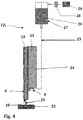
- FIG. 4 shows an embodiment of the application system according to the invention PA in side view and parking position 24.
- the reservoir 27 for the primer 26 is disposed above the applicator system PA according to the invention.
- a supply of compressed air 29, which with a compressed air control 28th can be regulated.
- the reservoir 27 is fluidly connected via the flexible supply line 25 to the primer liquid connection 9.
- the mechanics according to the FIG. 3 is covered by the protective cover 13.
- the application head 8 made of PTFE is lowered onto a closure pin 23, which is fastened to a machine component 22.
- the closure pin 23 pierces the suction belt 19 and is mounted on a spring, so that tolerances of the robot can be compensated thereby.
- the upper free end of the closure pin 23 is shaped so that it closes the nozzle opening 20 accurately.
- a feed of the high-pressure water-jet-reinforced polymer pulp web 19 or suction belt 19 takes place and a test application is carried out on a test strip.
- the trial order can be collected densitometrically or via a scanner. This ensures that the subsequent application of liquid, in particular primer, will be successful.
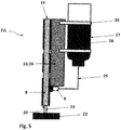
- FIG. 5 shows a further embodiment of the application system PA according to the invention in side view and parking position 24.
- the applicator PA according to the invention corresponds in its features to the application system PA of Figure 4 according to the invention, except that the primer reservoir 27 is attached to the protective cover 13 by means of brackets 30.
- the primer reservoir 27 is also here via a flexible supply line 25 for the primer 26 fluidly connected to the terminal 09.
- the primer 26 is conveyed from the reservoir 27 via the supply line 25 by gravity to the primer liquid port 09.
Description
- Die vorliegende Erfindung betrifft ein automatisiertes Primerauftragssystem (PA) zur Herstellung eines Anbauteils für Fortbewegungsmittel und ein Verfahren zum kontrollierten Auftragen von Primer-Flüssigkeiten auf Oberflächen von Anbauteilen.
- Auftragssysteme für Primer-Flüssigkeiten auf Scheibengrundkörpern sind bekannt. Sie werden verwendet, um die Scheibengrundkörper für die Verklebung vorzubereiten. Solche Primer-Flüssigkeiten werden üblicherweise manuell über kleine Fläschchen mit getrenntem Filzkopf auf die Scheiben aufgetragen, was einige Nachteile sowie einen erhöhten Materialaufwand mit sich bringt. So muss die Kontur der Klebelinie sehr genau abgefahren werden, um Primerfehlstellen oder Primerpfützen oder -läufer zu vermeiden. Außerdem müssen die Filze regelmäßig ausgetauscht werden, wobei auch immer eine beträchtliche Menge an Primer verlorengeht.
- Bei einigen automatisierten Verfahren wird die Primer-Flüssigkeit mittels eines Roboterarms auf die Scheibe aufgetragen, wobei aber auch hier mit Filzen gearbeitet wird. Diese Verfahren ermöglichen zwar eine präzise Primerabscheidung, was indes nicht die mit dem Einsatz von Filzen verbundenen Probleme löst. Zudem muss vom Roboter in regelmäßigen Intervallen der Filzkopf gewechselt werden, was einen zusätzlichen Mechanismus erfordert.
- So ist beispielsweise aus der deutschen Patentanmeldung
DE 102 49 726 A1 eine Flüssigkeitsausgabevorrichtung zum Auftragen von Flüssigkeiten auf eine aufnehmende Oberfläche bekannt. Die Ausgabevorrichtung arbeitet mit einem durchströmten Filzband. Die Ausgabevorrichtung kann einen oder mehrere Ausgabeköpfe aufweisen, die jeweils eine Ausgabepistole und einen gelenkigen Schleifblock umfassen. Der gelenkige Schleifblock umfasst eine Aussparung oder Nische unmittelbar hinter dem Filz, um eine geringe Ansammlung von flüssigem Material zum Durchsickern durch den Filz während eines Ausgabevorgangs vorzusehen. Die Ausgabevorrichtung kann gekippt werden, so dass der aufnehmenden Fläche jeweils nur ein Ausgabekopf präsentiert wird. Die Nische hat eine solche Geometrie, dass das Raupenprofil des auf die Oberfläche ausgegebenen flüssigen Materials verbessert wird. Flüssiges Material wird durch relative seitliche Bewegung zwischen der Vorrichtung und der aufnehmenden Fläche ausgegeben. Da das Filzband aber sehr dehnbar ist, umfasst die Ausgabevorrichtung eine aufwändig konstruierte Transportsteuerung, um eine reproduzierbare Ausgabe von Flüssigkeit zu gewährleisten. - Die Verwendung eines hochdruckwasserstrahlverfestigten Polymer-Zellstoffvlieses zum Auftragen von Primer-Flüssigkeiten geht aus
DE 600 31 995 T2 hervor. - Der vorliegenden Erfindung lag daher die Aufgabe zugrunde, die vorstehend beschriebenen Nachteile des Standes der Technik zu beheben, um insbesondere den Materialaufwand zu erniedrigen und Primerfehlstellen oder Primerpfützen oder -läufer zu vermeiden. Außerdem sollen für das Auftragen von Flüssigkeiten auf Oberflächen die Verwendung von Filzbändern und ein aufwändiges Transportsteuerungssystem vermieden werden.
- Insgesamt soll das Auftragen von Flüssigkeiten, insbesondere der Primer, auf Oberflächen, insbesondere der Oberfläche von Fahrzeuganbauteilen, ganz besonders von Fahrzeugscheiben, exakt reproduzierbar und materialsparend erfolgen.
- Demgemäß wurde das neue automatisierte Primerauftragssystem PA zur Herstellung von Anbauteilen für Fortbewegungsmittel gefun
- den, das ein hochdruckwasserstrahlverfestigtes Polymer-Zellstoffvlies umfasst und das im Folgenden als "erfindungsgemäßes Auftragssystem PA" bezeichnet wird. Dabei ist das hochdruckwasserstrahlverfestigte Polymer-Zellstoffvlies für den Auftrag einer Flüssigkeit vorgesehen.
- Außerdem wurde das neue Verfahren zum kontrollierten Auftragen von Primer-Flüssigkeiten auf Oberflächen gefunden, bei dem das erfindungsgemäße Primerauftragssystem PA verwendet wird und das im Folgenden als "erfindungsgemäßes Verfahren" bezeichnet wird.
- Im Hinblick auf den Stand der Technik war es überraschend und für den Fachmann nicht vorhersehbar, dass die Aufgaben, die der vorliegenden Erfindung zugrunde lagen, mit Hilfe des erfindungsgemäßen Auftragssystems PA und des erfindungsgemäßen Verfahrens gelöst werden konnten. Insbesondere konnten mit Hilfe des erfindungsgemäßen Auftragssystems und des erfindungsgemäßen Verfahrens die vorstehend beschriebenen Nachteile des Standes der Technik behoben werden. Überraschenderweise ließ sich der Materialaufwand erniedrigen und Primerfehlstellen oder Primerpfützen oder -läufer vermeiden. Außerdem konnte für das Auftragen von Flüssigkeiten auf Oberflächen die Verwendung von Filzbändern und ein aufwändiges Transportsteuerungssystem vermieden werden. Insgesamt war das Auftragen von Flüssigkeiten, insbesondere von Primer-Flüssigkeiten auf Oberflächen, insbesondere der Oberfläche von Fahrzeugscheiben, exakt reproduzierbar und materialsparend. Vor allem aber kamen die erfindungsgemäßen Auftragssysteme mit einem Minimum an beweglichen Teilen aus, so dass das unerwünschte Austrocknen der Flüssigkeiten bei der Applikation oder in der Parkposition der erfindungsgemäßen Auftragssysteme signifikant reduziert oder völlig verhindert wurde.
- Die vorliegende Erfindung betrifft ein automatisiertes Primerauftragssystem zur Herstellung von Anbauteilen für Fortbewegungsmittel. Das automatisierte Primerauftragssystem umfasst mindestens ein hochdruckwasserstrahlverfestigtes Polymer-Zellstoffvlies, eine Ausgabespule für sauberes, das heißt unbenutztes hochdruckwasserstrahlverfestigtes Polymer-Zellstoffvlies und eine Aufnahmespule für gebrauchtes, das heißt bereits mit einer Bauteiloberfläche in Kontakt gestandenes hochdruckwasserstrahlverfestigtes Polymer-Zellstoffvlies. Außerdem umfasst das automatisierte Primerauftragssystem einen Auftragskopf mit einer Düsenöffnung. Das hochdruckwasserstrahlverfestigte Polymer-Zellstoffvlies wird von der Ausgabespule über den Auftragskopf zur Aufnahmespule gelenkt und ist vor der Düsenöffnung angeordnet. Durch die Düsenöffnung ist eine Primer-Flüssigkeit zuführbar, so dass Primer-Flüssigkeit über das Polymer-Zellstoffvlies auf einer Bauteiloberfläche auftragbar ist.
- Bei der Applikation der Flüssigkeiten, insbesondere der Primer, mit dem erfindungsgemäßen automatisierten Primerauftragssystem wird das hochdruckwasserstrahlverfestigte Polymer-Zellstoffvlies durchtränkt und gibt so die Flüssigkeit an die Oberfläche, vorzugsweise an die Glas-, Keramik- oder Kunststoffoberfläche und insbesondere an den Scheibengrundkörper weiter. Im Gegensatz zur herkömmlichen Methode über die Filze nimmt das hochdruckwasserstrahlverfestigte Polymer-Zellstoffvlies deutlich weniger Flüssigkeit, insbesondere deutlich weniger Primer auf, so dass bei einem Wechsel oder Weitertakten des Gewirkes weniger Flüssigkeit, insbesondere weniger Primer, verworfen werden muss. Zudem wird die Bildung von Primerpfützen und Primerläufern verringert. Der Wechsel des Gewirkes im Rahmen des erfindungsgemäßen Verfahrens erfolgt mithilfe des erfindungsgemäßen Auftragssystems über das Rollensystem aus Ausgabespule und Aufnahmespule ähnlich einer Filmrolle, wobei das Rollensystem das hochdruckwasserstrahlverfestigte Polymer-Zellstoffvlies, jeweils lediglich um einige Zentimeter verschieben muss.
- Die vorliegende Erfindung erzielt ihre Vorteile, indem die Primer oder andere Flüssigkeiten nicht über Filzköpfe oder Filzbänder appliziert werden, sondern über eine Düse mit einem vorgespannten hochdruckwasserstrahlverfestigten Polymer-Zellstoffvlies, wobei die Flüssigkeit das Gewirke durchtränkt und so die Flüssigkeit an die Oberfläche, vorzugsweise eine Glas-, Keramik- oder Kunststoffoberfläche und insbesondere einen Scheibengrundkörper für eine Fahrzeugscheibe, weitergeben kann. Das hochdruckwasserstrahlverfestigte Polymer-Zellstoffvlies hat bevorzugt eine Dicke von 0,1 mm bis 2 mm, besonders bevorzugt von 0,2 mm bis 1 mm. Bei diesen Materialstärken wird der Verlust an Primer-Flüssigkeit beim Weitertakten von gebrauchtem getränktem Vlies vorteilhaft reduziert, wobei gleichzeitig das Vlies eine sehr gute Stabilität zeigt.
- Als Polymere des Polymer-Zellstoffvlieses kommen alle technischen Kunststoffe in Betracht, die Fasern bilden können, die sich mit einem Hochdruckwasserstrahl ohne Zersetzung verformen und mit anderen Faserstoffen wie Zellstoffvliesen haftfest verbinden lassen. Besonders bevorzugt werden thermoplastische Polyester, insbesondere Polyethylenterephthalat (PET) verwendet. Mit PET-Zellstoffvliesen wurden besonders gute Ergebnisse erzielt.
- Vorzugsweise enthält das hochdruckwasserstrahlverfestigte Polymer-Zellstoffvlies, bezogen auf seine jeweilige Gesamtmenge, 40 Gew.-% bis 60 Gew.-% Polyester und 60 Gew.-% bis 40 Gew.-% Zellstoff, insbesondere 48 Gew.-% Polyester und 52 Gew.-% Zellstoff oder es besteht aus diesen.
- Besonders bevorzugt enthält das hochdruckwasserstrahlverfestigte Polyester-Zellstoffvlies, bezogen auf seine jeweilige Gesamtmenge, 40 bis 60 Gew.-% Polyester und 60 bis 40 Gew.-% Zellstoff, insbesondere 48 Gew.-% Polyester und 52 Gew.-% Zellstoff oder es besteht aus diesen. Materialien dieser Art sind bekannt und werden zum Beispiel unter der Marke DuPont Sontara® Print Master vertrieben. Diese Sontara®-Vliese werden als Spezialwaschvliese für Druckmaschinen mit Wendeeinrichtung und rauem Druckzylinder vertrieben. Die Sontara®-Vliese (vgl. das amerikanische Patent
US 3,837,995 ) wurden beispielsweise in chirurgischen Gesichtsmasken (vgl. deutsche PatentanmeldungDE 36 01 449 A1 ) und in medizinischen Abdecktüchern (vgl. europäisches PatentEP 0 197 048 B1 ) verwendet. Eine Verwendung der Sontara®-Vliese bei der Herstellung von Anbauteilen für Fortbewegungsmitteln ist nicht bekannt. - Im Rahmen der vorliegenden Erfindung werden unter Anbauteilen für Fortbewegungsmittel Fahrzeugscheiben, Fahrzeugdächer, Spoilerelemente, Säulenabdeckungen, Dachpanele, Dichtungen und Zierleisten, oder dergleichen verstanden. Unter Fortbewegungsmitteln werden Fortbewegungsmittel zu Lande, insbesondere Kraftfahrzeuge, Busse oder Züge, Fortbewegungsmittel zur Luft, insbesondere Flugzeuge, Ballons oder Zeppeline, und Fortbewegungsmittel zu Wasser, insbesondere Schiffe und Boote, verstanden.
- Der Begriff Fahrzeugscheiben schließt im Rahmen der vorliegenden Erfindung Scheiben aus Mineralglas oder Kunststoff mit ein. Die Scheiben können flach oder gebogen bzw. dreidimensional ausgestaltet sein und einen Schwarzrand aufweisen. Der Schwarzrand kann durch Siebbedruckung mit einer geeigneten keramischen oder organischen Siebdruckpaste, oder durch Anspritzung einer polymeren Materialschicht, hergestellt sein. Des Weiteren können die Scheiben zusätzliche Elemente wie beispielsweise Befestigungsdome, Zierdekors oder Weichkomponenten aufweisen. In einer bevorzugten Ausführungsform umfasst das automatisierte Primerauftragssystem mindestens eine Trägerplatte und eine Umlenkrolle. Auf der Trägerplatte sind die Aufnahmespule für das gebrauchte hochdruckwasserstrahlverfestigte Polymer-Zellstoffvlies und die Ausgabespule für das saubere hochdruckwasserstrahlverfestigte Polymer-Zellstoffvlies angeordnet. Die Ausgabespule ist mit Hilfe von einer oder mehreren ersten Buchsen drehbar auf der Trägerplatte angeordnet. Die Aufnahmespule ist mit Hilfe mindestens einer zweiten Buchse drehbar auf der Trägerplatte angeordnet. Das Primerauftragssystem umfasst außerdem eine der drehbaren Ausgabespule zugeordnete Umlenkrolle. Die Umlenkrolle ist so angeordnet, dass das saubere hochdruckwasserstrahlverfestigte Polymer-Zellstoffvlies von der Ausgabespule über die Umlenkrolle zur Düsenöffnung des Auftragskopfs gelenkt wird, wo es mit der Primer-Flüssigkeit getränkt wird, und von da aus der Aufnahmespule zugeführt und dort aufgewickelt wird. Durch die Führung des Polymer-Zellstoffvlieses über die Umlenkrolle wird eine optimale Vorspannung des Polymer-Zellstoffvlieses erzielt.
- In einer bevorzugten Ausführungsform des automatisierten Primerauftragssystems ist das hochdruckwasserstrahlverfestigte Polymer-Zellstoffvlies über die Aufnahmespule, die Ausgabespule, den Auftragskopf mit der Düsenöffnung und 1 bis 3 Umlenkrollen geführt. Aufgrund der Eigenschaften des hochdruckwasserstrahlverfestigten Polmyer-Zellstoffvlieses ist kein kompliziertes Transportsystem nötig, da eine gute Vorspannung bereits mit einem aus nur wenigen Rollen bestehenden System erzielt wird. Bevorzugt sind nur 1 bis 2 Umlenkrollen, besonders bevorzugt ist nur 1 Umlenkrolle Bestandteil des automatisierten Primerauftragssystems. Mit einer Umlenkrolle wird das System und damit auch die Produktion kostengünstiger und das System benötigt weniger Platz am Produktionsstandort und kann flexibler eingesetzt werden auch für kleine Bauteile.
- Bevorzugt ist die Ausgabespule auf der Trägerplatte oberhalb der Aufnahmespule angeordnet. So kann keine am gebrauchten Polymer-Zellstoffvlies haftende Primer-Flüssigkeit durch die Wirkung der Schwerkraft auf das saubere Polymer-Zellstoffvlies auf der Ausgabespule tropfen.
- Die Breite der Polymer-Zellstoffvliese kann breit variieren und richtet sich vor allem nach der gewünschten Breite der aufgetragenen Spur auf der Oberfläche. Es ist aber auch möglich, die gewünschte Breite nicht mit einem Durchgang des erfindungsgemäßen Verfahrens, sondern mit mehreren Durchgängen zu erreichen.
- Das erfindungsgemäße Primerauftragssystem besitzt einen Auftragskopf, der vorzugsweise aus Polytetrafluorethylen (PTFE, Teflon®) oder Polytrifluorchlorethylen (PCTFE) gefertigt ist.
- Dieser hat den Vorteil, dass die Primer-Flüssigkeit an dem Material nur geringfügig haftet, so dass das hochdruckwasserstrahlverfestigte Polyester-Zellstoffvlies problemlos weiter getaktet werden kann.
- In einer bevorzugten Ausführungsform des automatisierten Primerauftragssystem umfasst der Auftragskopf einen Anschluss für die Primer-Flüssigkeit, die über eine Zufuhrleitung von einem Primer-Vorratsbehälter zugeführt wird, sowie einen Verschlußstift, der die Düsenöffnung verschließt, sobald das Primerauftragssystem in eine Parkposition geht.
- Bei dem erfindungsgemäßen Auftragssystem PA erfolgt im Rahmen des erfindungsgemäßen Verfahrens die Zudosierung der Flüssigkeit, insbesondere des Primers über ein flexibles Schlauchsystem, über das die Flüssigkeit druckgesteuert aus einem Vorratsbehälter nachdosiert wird. Die exakte Mengendosierung erfolgt über den Vorratsbehälter, der mit einem geringen Überdruck beaufschlagt wird. Der Überdruck kann mit einem Ventil exakt geregelt werden. Diese Methode erlaubt eine sehr präzise steuerbare Zudosierung der Flüssigkeit, insbesondere des Primers, wodurch der Materialbedarf weiter gesenkt und der Auftragswirkungsgrad gesteigert wird. In der Parkposition des erfindungsgemäßen Auftragssystems PA wird der Überdruck im Vorratsbehälter abgebaut. Dadurch wird verhindert, dass noch Flüssigkeit am Auftragskopf nachläuft und tropft. Wenn notwendig, besteht zusätzlich die Möglichkeit im Vorratsbehälter ein Vakuum zu erzeugen.
- Die Zufuhr der Flüssigkeit, insbesondere des Primers, kann im Rahmen des erfindungsgemäßen Verfahrens auch durch die Schwerkraft erfolgen.
- Somit sind für die Zufuhr der Flüssigkeit, insbesondere des Primers, keine beweglichen Teile, an den sich der Primer festsetzen und eintrocknen kann, erforderlich, was einen weiteren besonderen Vorteil des erfindungsgemäßen Auftragsgeräts darstellt.
- In einer bevorzugten Ausführungsform des automatisiertes Primerauftragssystems ist auf der Rückseite der Trägerplatte eine Mechanik angeordnet, die den Takt des Vorschubs für das hochdruckwasserstrahlverfestigte Polymer-Zellstoffvlies vorgibt und die die folgenden funktionell einander zugeordneten Bestandteile umfasst: einen Takthebel, eine Hebellagerung, eine erste Feder, die eine variable Kraft auf den Takthebel ausübt, ein der zweiten Aufnahmespule zugeordnetes Sperrad, einen Rasthebel, der über eine zweite Feder mit einer Sperrklinke gekoppelt ist, sowie eine Schutzabdeckung für die Mechanik. Dieser Aufbau stellt einen geregelten und besonders effizienten Vorschub des hochdruckwasserstrahlverfestigten Polymer-Zellstoffvlies sicher. Die Rückseite der Trägerplatte liegt gegenüber der Seite, auf der die Aufnahmespule und Ausgabespule befestigt sind.
- Der Ablauf des erfindungsgemäßen Verfahrens zum kontrollierten Auftragen von Primer-Flüssigkeiten auf Oberflächen von Anbauteilen für Fortbewegungsmittel mit Hilfe des erfindungsgemäßen automatisierten Primerauftragssystems läßt sich wie folgt beschreiben: Zunächst wird ein Anbauteil bereitgestellt. Der Auftragskopf mit dem getränkten hochdruckwasserstrahlverfestigten Polymer-Zellstoffvlies wird auf der Bauteiloberfläche aufgesetzt. Durch die Düsenöffnung im Auftragskopf wird Primer-Flüssigkeit dem hochdruckwasserstrahlverfestigen Polymer-Zellstoffvlies zugeführt. Die Bauteiloberfläche oder das hochdruckwasserstrahlverfestigte Polymer-Zellstoffvlies wird entlang der mit Primer-Flüssigkeit zu versehenden Konturen bewegt. In einem letzten Schritt wird der Kontakt zwischen dem Auftragskopf mit dem getränkten hochdruckwasserstrahlverfestigtem Polymer-Zellstoffvlies und der Bauteiloberfläche gelöst, das heißt das Anbauteil wird entfernt. Mit diesem Verfahren können Anbauteile für Fortbewegungsmittel automatisiert mit einem Primer versehen werden, ohne dass unschöne PrimerPfützen gebildet werden.
- Das erfindungsgemäße Auftragssystem wird bevorzugt von einem Roboter nach den Konturen der Auftragung bewegt und gesteuert. Während des Auftragens wird die Flüssigkeit oder der Primer, wie oben beschrieben, kontinuierlich über den Auftragskopf zugeführt.
- In einer bevorzugten Ausführungsform des erfindungsgemäßen Verfahrens wird das erfindungsgemäße Auftragsgerät nach dem Lösen des Kontakts zwischen Auftragskopf und Bauteiloberfläche in eine Warteposition, bzw. bei längerem Stillstand, in eine Parkposition gebracht. In der Warteposition verharrt die PA bis zur Zuführung des nächsten Bauteils. In der Parkposition wird die Düsenöffnung für die Flüssigkeit, insbesondere den Primer, mit einem Verschlussstift verschlossen. Das getränkte hochdruckwasserstrahlverfestigte Polymer-Zellstoffvlies wird eine Position weiter getaktet, so dass sauberes Polymer-Zellstoffvlies vor der Düsenöffnung angeordnet ist. Dies erfolgt bevorzugt mit Hilfe einer Mechanik, die über einen Hebel und ein Sperrad verfügt. Der Hebel selbst wird durch den Roboter betätigt. Das Verschließen der Düsenöffnung geschieht bevorzugt in einfacher Weise dadurch, dass das erfindungsgemäße Auftragssystem auf einen Verschlussstift abgesenkt wird, dessen oberes, freies Ende so geformt ist, dass er die Düsenöffnung passgenau verschließt. Der Verschlußstift kann in einer weiteren Ausführungsform auf einer Feder gelagert sein, so dass gegebenenfalls vorhandene Toleranzen des Roboters ausgeglichen werden.
- Der Verschlußstift kann das hochdruckwasserstrahlverfestigte Polymer-Zellstoffvlies, insbesondere das Polyester-Zellstoffvlies, durchstoßen, ohne dass das Vlies zerreißt.
- Bei dem Neustart wird das erfindungsgemäße Auftragsgerät wieder vom Verschlußstift gelöst, die Düsenöffnung wird wieder freigegeben und das Auftragsgerät wird in eine Auftragsposition gefahren. In der Auftragsposition befindet sich der Auftragskopf wieder über einer Bauteiloberfläche, auf die eine Flüssigkeit aufgetragen werden soll.
- Erfindungsgemäß ist es weiterhin von Vorteil, wenn bei einem Neustart zunächst ein Vorschub des hochdruckwasserstrahlverfestigten Polymer-Zellstoffvlieses oder Saugbands erfolgt und ein Probeauftrag auf einem Teststreifen durchgeführt wird. Der Probeauftrag kann densitometrisch oder über einen Scanner erfasst werden. Dadurch ist sichergestellt, dass der anschließende Auftrag von Flüssigkeit, insbesondere von Primer, erfolgreich ablaufen wird.
- Bevorzugt sind die Bauteiloberflächen Glas-, Keramik- oder Kunststoffoberflächen.
- Gezeigt, aber nicht Teil der Erfindung, ist die Verwendung eines hochdruckwasserstrahlverfestigten Polymer-Zellstoffvlieses zum Auftragen von Primer-Flüssigkeiten bei der Herstellung eines Anbauteils für Fortbewegungsmittel. Bevorzugt ist dabei das Polymer ein Polyester, besonders bevorzugt ein Polyethylenterephthalat (PET).
- Vorzugsweise werden die hochdruckwasserstrahlverfestigten Polymer-Zellstoffvliese bei der Herstellung von Kraftfahrzeugen, insbesondere bei der Herstellung von Fahrzeugscheiben, Fahrzeugdächern, Spoilerelementen, Dachpanelen oder Zierleisten verwendet.
- Insbesondere werden die hochdruckwasserstrahlverfestigten Polymer-Zellstoffvliese für die Vorbereitung der Direktverklebung von Fahrzeugscheiben mit Karosserien verwendet.
- Es versteht sich von selbst, dass die vorstehend und nachstehend näher erläuterten Merkmale nicht nur in den angegebenen Kombinationen und Konfigurationen, sondern auch in anderen Kombinationen und Konfigurationen oder in Alleinstellung einsetzbar sind, ohne den Rahmen der vorliegenden Erfindung zu verlassen.
- Die Erfindung wird nun anhand von Ausführungsbeispielen näher erläutert, wobei Bezug auf die beigefügten
Figuren 1 bis 5 genommen wird. Es zeigen in vereinfachter, nicht in maßstäblicher Darstellung: - Figur 1
- eine Draufsicht auf die Vorderansicht des automati-sierten Primerauftragssystems PA;
- Figur 2
- eine Draufsicht auf einen Längsschnitt durch das automatisierte Primerauftragssystem PA längs seiner Mittellinie;
- Figur 3
- eine Draufsicht auf die Rückansicht des automatisierten Primerauftragssystems PA ohne den Schutz 13;
- Figur 4
- eine Draufsicht auf die Seitenansicht des automatisierten Primerauftragssystem PA in Parkposition;
- Figur 5
- eine Draufsicht auf die Seitenansicht einer weiteren Ausführungsform des automatisierten Primerauftragssystem PA in Parkposition.
- Die
Figur 1 zeigt eine Draufsicht auf die Vorderansicht des erfindungsgemäßen Auftragssystems PA mit einer Trägerplatte 01. Im oberen Bereich der Trägerplatte 01 ist eine mit Hilfe der ersten Buchsen 10 und 11 drehbar gelagerte Ausgabespule 02 für das saubere Saugband 19 einer Breite von 1,5 cm und einer Dicke von 1 mm angeordnet. Als Saugband 19 wird erfindungsgemäß ein hochdruckwasserstrahlverfestigtes Polyester-Zellstoffvlies verwendet, das, bezogen auf das Vlies, aus 48 Gew.-% Polyester und 52 Gew.-% Zellstoff besteht. Die Ausgabespule 02 ist oberhalb der mit Hilfe der zweiten Buchse 12 drehbar auf der Trägerplatte 01 angeordneten Aufnahmespule 03 für das gebrauchte Saugband 19 angeordnet. Der drehbaren Ausgabespule 02 ist eine Umlenkrolle 21 zugeordnet, von der aus das saubere hochdruckwasserstrahlverfestigte Polyester-Zellstoffvlies 19 zu der Düsenöffnung 20 des Auftragskopfs 8 aus PTFE gelenkt wird. Dort wird es mit dem Primer 26 getränkt. Von der Düsenöffnung 20 wird es einer der mit Hilfe der zweiten Buchse 12 auf der Trägerplatte 01 drehbar angeordneten Aufnahmespule 03 zugeführt und dort aufgewickelt. - Der Auftragskopf 8 wird mit einem computergesteuerten Roboter (nicht gezeigt) über die Oberfläche, insbesondere über die Glas-, Keramik- oder Kunststoffoberfläche eines Scheibengrundkörpers einer Fahrzeugscheibe (nicht gezeigt) geführt, wodurch der Primer 26 in der gewünschten Konfiguration abgeschieden wird.
- Die
Figur 2 zeigt die Draufsicht auf einen Längsschnitt längs der Mittellinie der Trägerplatte 01. - Sichtbar sind der Auftragskopf 08 mit der Düsenöffnung 20 und dem Anschluss 9 für den Primer 26. Die gesamte Anordnung ohne den Auftragskopf 8 ist durch eine Schutzabdeckung 13 aus Kunststoff oder Metall geschützt.
- Die
Figur 3 zeigt eine Draufsicht auf die Rückansicht des erfindungsgemäßen Auftragssystems PA ohne die Schutzabdeckung 13. Hiernach ist auf der Rückseite der Trägerplatte 01 eine Mechanik angeordnet, die den Takt des Vorschubs für das hochdruckwasserstrahlverfestigte Polyester-Zellstoffvlies vorgibt und die vorzugsweise die folgenden funktionell einander zugeordneten Bestandteile umfasst: - einen Takthebel 04,
- eine Hebellagerung 18,
- eine erste Feder 14, die eine variable Kraft auf den Takthebel 04 ausübt,
- ein der Aufnahmespule 03 zugeordnetes Sperrad 06,
- einen Rasthebel 07, der über eine zweite Feder 15 mit
- einer Sperrklinke 05 gekoppelt ist, sowie
- eine Schutzabdeckung 13 für die Mechanik.
- Der Takt wird mit Hilfe eines computergesteuerten Roboters vorgegeben.
- Die
Figur 4 zeigt eine Ausführungsform des erfindungsgemäßen Auftragssystems PA in Seitenansicht und Parkposition 24. Der Vorratsbehälter 27 für den Primer 26 ist oberhalb des erfindungsgemäßen Auftragssystems PA angeordnet. An dem Vorratsbehälter 27 befindet sich oberhalb des Flüssigkeitsspiegels eine Zufuhr für Druckluft 29, die mit einer Druckluftregelung 28 geregelt werden kann. Der Vorratsbehälter 27 ist über die flexible Zufuhrleitung 25 mit dem Anschluss 9 für Primerflüssigkeit fluidmäßig verbunden. Die Mechanik gemäß derFigur 3 wird durch die Schutzabdeckung 13 abgedeckt. Der Auftragskopf 8 aus PTFE wird auf einen Verschlussstift 23 abgesenkt, der an einem Maschinenbauteil 22 befestigt ist. Der Verschlussstift 23 durchstößt das Saugband 19 und ist auf einer Feder gelagert, so dass Toleranzen des Roboters hierdurch ausgeglichen werden können. Das obere freie Ende des Verschlußstifts 23 ist so geformt, dass es die Düsenöffnung 20 passgenau verschließt. - Bei dem Neustart wird das erfindungsgemäße Auftragsgerät wieder vom Verschlussstift gelöst, die Düsenöffnung wird wieder freigegeben und das Auftragsgerät wird in eine Auftragsposition gefahren.
- Erfindungsgemäß ist es von Vorteil, wenn bei einem Neustart zunächst ein Vorschub des hochdruckwasserstrahlverfestigten Polymer-Zellstoffvlieses 19 oder Saugbands 19 erfolgt und ein Probeauftrag auf einem Teststreifen durchgeführt wird. Der Probeauftrag kann densitometrisch oder über einen Scanner erfasst werden. Dadurch ist sichergestellt, dass der anschließende Auftrag von Flüssigkeit, insbesondere von Primer, erfolgreich ablaufen wird.
- Die
Figur 5 zeigt eine weitere Ausführungsform des erfindungsgemäßen Auftragssystems PA in Seitenansicht und Parkposition 24. Das erfindungsgemäße Auftragssystem PA entspricht in seinen Merkmalen dem erfindungsgemäßen Auftragssystem PA der Figur 4, nur dass der Primer-Vorratsbehälter 27 an der Schutzabdeckung 13 mithilfe von Halterungen 30 befestigt ist. Der Primer-Vorratsbehälter 27 ist auch hier über eine flexible Zufuhrleitung 25 für den Primer 26 mit dem Anschluss 09 fluidmäßig verbunden. Bei dieser Ausführungsform wird der Primer 26 von dem Vorratsbehälter 27 über die Zufuhrleitung 25 durch die Schwerkraft zu dem Anschluss 09 für die Primer- Flüssigkeit gefördert. -
- PA
- Primerauftragssystem
- 01
- Trägerplatte
- 02
- Ausgabespule für das saubere Band aus hochdruckwasserstrahlverfestigtes Polymer-Zellstoffvlies
- 03
- Aufnahmespule für das gebrauchte Band aus hochdruckwasserstrahlverfestigtes Polymer-Zellstoffvlies
- 04
- Takthebel
- 05
- Sperrklinke
- 06
- Sperrrad
- 07
- Rasthebel
- 08
- Auftragskopf
- 09
- Anschluss für Primerflüssigkeit
- 10
- erste Buchse
- 11
- erste Buchse
- 12
- zweite Buchse
- 13
- Schutzabdeckung
- 14
- erste Feder
- 15
- zweite Feder
- 16
- Bolzen
- 17
- dritte Buchse
- 18
- Hebellagerung
- 19
- hochdruckwasserstrahlverfestigtes Polymer-Zellstoffvlies oder Saugband
- 20
- Düsenöffnung
- 21
- Umlenkrolle
- 22
- Maschinenbauteil auf dem der Verschlußstift 23 befestigt ist
- 23
- Verschlußstift
- 24
- Auftragsgerät in Parkposition
- 25
- Zufuhrleitung für die Primer-Flüssigkeit 26
- 26
- Primer-Flüssigkeit oder Primer
- 27
- Primer-Vorratsbehälter
- 28
- Druckluftregelung
- 29
- Druckluftversorgung
- 30
- Halterung für den Primer-Vorratsbehälter 27
Claims (11)
- Automatisiertes Primerauftragssystem (PA) zur Herstellung von Anbauteilen für Fortbewegungsmittel, mindestens umfassend eine Ausgabespule (2), eine Aufnahmespule (3), einen Auftragskopf (8) mit einer Düsenöffnung (20) und ein hochdruckwasserstrahlverfestigtes Polymer-Zellstoffvlies (19), wobei- das hochdruckwasserstrahlverfestigte Polymer-Zellstoffvlies (19) von der Ausgabespule (2) über den Auftragskopf (8) zur Aufnahmespule (3) gelenkt wird,- das hochdruckwasserstrahlverfestigte Polymer-Zellstoffvlies (19) vor der Düsenöffnung (20) angeordnet ist und durch die Düsenöffnung (20) eine Primer-Flüssigkeit (26) zuführbar ist, sodass die Primer-Flüssigkeit (26) über das Polymer-Zellstoffvlies (19) auf eine Bauteiloberfläche auftragbar ist.
- Automatisiertes Primerauftragssystem (PA) nach Anspruch 1, wobei das Polymer ein Polyester ist.
- Automatisiertes Primerauftragssystem (PA) nach Anspruch 1 oder 2, wobei der Polyester Polyethylenterephthalat (PET) ist.
- Automatisiertes, Primerauftragssystem (PA) nach einem der Ansprüche 1 bis 3, wobei die hochdruckwasserstrahlverfestigten Polymer-Zellstoffvliese, jeweils bezogen auf das Polymer-Zellstoffvlies, 40 Gew.-% bis 60 Gew.-% Polyester und 60 Gew.-% bis 40 Gew.-% Zellstoffvlies enthalten oder hieraus bestehen.
- Automatisiertes Primerauftragssystem (PA) nach einem der Ansprüche 1 bis 4 mindestens umfassend eine Trägerplatte (01) und eine Umlenkrolle (21), wobei- die Ausgabespule (02) für das saubere hochdruckwasserstrahlverfestigte Polymer-Zellstoffvlies (19) mithilfe von einer ersten Buchse (10, 11) drehbar auf der Trägerplatte (01) angeordnet ist,- die Aufnahmespule (03) für das gebrauchte hochdruckwasserstrahlverfestigte Polymer- Zellstoffvlies (19) mithilfe einer zweiten Buchse (12) drehbar auf der Trägerplatte (01) angeordnet ist und- der drehbaren Ausgabespule (02) die Umlenkrolle (21) zugeordnet ist, von der aus das saubere hochdruckwasserstrahlverfestigte Polymer-Zellstoffvlies (19) zur Düsenöffnung (20) des Auftragskopfs (08) gelenkt wird, wo es mit der Primer-Flüssigkeit (26) getränkt wird, und von da aus der Aufnahmespule (03) zugeführt und dort aufgewickelt wird.
- Automatisiertes Primerauftragsystem (PA) nach einem der Ansprüche 1 bis 5, wobei das hochdruckwasserstrahlverfestigte Polymer-Zellstoffvlies (19) über die Aufnahmespule (3), die Ausgabespule (2), den Auftragskopf (8) mit der Düsenöffnung (20) und 1 bis 3 Umlenkrollen (21), bevorzugt 1 bis 2 Umlenkrollen (21), besonders bevorzugt 1 Umlenkrolle (21) geführt ist.
- Automatisiertes Primerauftragssystem nach einem der Ansprüche 1 bis 6, wobei der Auftragskopf (08) einen Anschluss (09) für die Primer-Flüssigkeit (26), die über eine Zufuhrleitung (25) von einem Primer-Vorratsbehälter (27) zugeführt wird, sowie einen Verschlussstift (23) zum Verschließen der Düsenöffnung (20) sobald das Primerauftragssystem (PA) in eine Parkposition (24) geht, umfasst.
- Automatisiertes Primerauftragssystem (PA) nach einem der Ansprüche 5 bis 7, wobei auf der Rückseite der Trägerplatte (01) eine Mechanik angeordnet ist, die den Takt des Vorschubs für das hochdruckwasserstrahlverfestigte Polymer-Zellstoffvlies (19) vorgibt und die die folgenden funktionell einander zugeordneten Bestandteile umfasst:- einen Takthebel (04),- eine Hebellagerung (18),- eine erste Feder (14), die eine variable Kraft auf den Takthebel (04) ausübt,- ein der zweiten Aufnahmespule (03) zugeordnetes Sperrrad (06),- einen Rasthebel (07), der über eine zweite Feder (15) mit- einer Sperrklinke (05) gekoppelt ist, sowie- eine Schutzabdeckung (13) für die Mechanik.
- Verfahren zum kontrollierten Auftragen von Primer-Flüssigkeiten auf Oberflächen von Anbauteilen für Fortbewegungsmittel mithilfe eines automatisierten Primerauftragssystems (PA) nach einem der Ansprüche 1 bis 8, wobei das Verfahren mindestens die Schritte- Bereitstellen eines Anbauteils,- Aufsetzen des Auftragskopfs (8) mit getränktem hochdruckwasserstrahlverfestigten Polymer-Zellstoffvlies (19) auf der Bauteiloberfläche,- Bewegen der Bauteiloberfläche oder des Auftragskopfes (8) entlang der mit Primer-Flüssigkeit (26) zu versehenden Konturen und- Lösen des Kontakts zwischen Auftragskopf (8) mit getränktem hochdruckwasserstrahlverfestigtem Polymer-Zellstoffvlies (19) und Bauteiloberfläche umfasst, wobei Primer-Flüssigkeit (26) durch die Düsenöffnung (20) im Auftragskopf (8) zugeführt wird.
- Verfahren nach Anspruch 9, wobei- nach dem Lösen des Kontakts zwischen Auftragskopf (8) und Bauteiloberfläche das hochdruckwasserstrahlverfestigte Polymer-Zellstoffvlies (19) eine Position weiter getaktet wird, sodass sauberes Polymer-Zellstoffvlies (19) vor der Düsenöffnung (20) angeordnet ist und- das automatisierte Primerauftragssystem (PA) in eine Parkposition gebracht wird, in der die Düsenöffnung (20) mit einem Verschlussstift (23) verschlossen wird.
- Verfahren nach einem der Ansprüche 9 oder 10, wobei die Bauteiloberflächen Glas-, Keramik- oder Kunststoffoberflächen sind.
Priority Applications (1)
| Application Number | Priority Date | Filing Date | Title |
|---|---|---|---|
| PL16775240T PL3359304T3 (pl) | 2015-10-07 | 2016-09-29 | Zautomatyzowany system nanoszenia podkładu |
Applications Claiming Priority (2)
| Application Number | Priority Date | Filing Date | Title |
|---|---|---|---|
| EP15188780 | 2015-10-07 | ||
| PCT/EP2016/073356 WO2017060162A1 (de) | 2015-10-07 | 2016-09-29 | Automatisiertes primerauftragssystem |
Publications (2)
| Publication Number | Publication Date |
|---|---|
| EP3359304A1 EP3359304A1 (de) | 2018-08-15 |
| EP3359304B1 true EP3359304B1 (de) | 2019-08-14 |
Family
ID=54337107
Family Applications (1)
| Application Number | Title | Priority Date | Filing Date |
|---|---|---|---|
| EP16775240.1A Active EP3359304B1 (de) | 2015-10-07 | 2016-09-29 | Automatisiertes primerauftragssystem |
Country Status (12)
| Country | Link |
|---|---|
| US (1) | US20180243782A1 (de) |
| EP (1) | EP3359304B1 (de) |
| JP (1) | JP6625739B2 (de) |
| KR (1) | KR102099027B1 (de) |
| CN (1) | CN106999975B (de) |
| CA (1) | CA2997948C (de) |
| ES (1) | ES2755408T3 (de) |
| MX (1) | MX2018004105A (de) |
| PL (1) | PL3359304T3 (de) |
| PT (1) | PT3359304T (de) |
| RU (1) | RU2687421C1 (de) |
| WO (1) | WO2017060162A1 (de) |
Families Citing this family (3)
| Publication number | Priority date | Publication date | Assignee | Title |
|---|---|---|---|---|
| CN111002918A (zh) * | 2018-10-07 | 2020-04-14 | 聂艺泽 | 一种自发光、反光车标及制作方法 |
| TWI761768B (zh) * | 2020-02-19 | 2022-04-21 | 陽程科技股份有限公司 | 可利用放捲無塵布控制塗佈頭塗層厚度之塗佈機 |
| CN112827750B (zh) * | 2020-12-31 | 2021-11-23 | 江苏智配新材料科技有限公司 | 一种套线表层涂饰材料的加工系统 |
Family Cites Families (16)
| Publication number | Priority date | Publication date | Assignee | Title |
|---|---|---|---|---|
| US3837995A (en) | 1972-04-24 | 1974-09-24 | Kimberly Clark Co | Autogenously bonded composite web |
| FR2229797B1 (de) * | 1973-05-18 | 1976-05-28 | Rhone Poulenc Textile | |
| DE3317124A1 (de) * | 1983-05-07 | 1984-11-08 | Teroson Gmbh, 6900 Heidelberg | Vorrichtung zum auftragen von fluessigkeiten mit unterschiedlicher konsistenz |
| US4627427A (en) | 1984-10-17 | 1986-12-09 | Minnesota Mining And Manufacturing Company | Universal medical cover sheet and process for draping |
| US4635628A (en) | 1985-09-11 | 1987-01-13 | Tecnol, Inc. | Surgical face mask with improved moisture barrier |
| JP3071114B2 (ja) * | 1993-12-15 | 2000-07-31 | 日新製鋼株式会社 | 連続焼鈍炉,連続塗装設備等の区画出入口のシール装置 |
| JPH11226465A (ja) * | 1998-02-12 | 1999-08-24 | Konica Corp | 塗布方法及び塗布装置 |
| AU8006200A (en) * | 1999-10-08 | 2001-04-23 | Procter & Gamble Company, The | Applicator having a temperature changing element for distributing a product ontoa target surface |
| JP3878440B2 (ja) * | 2001-06-29 | 2007-02-07 | 大日本スクリーン製造株式会社 | 基板塗布装置 |
| US6695917B2 (en) | 2001-11-14 | 2004-02-24 | Nordson Corporation | Flow through felt dispenser |
| EP1410900A1 (de) * | 2002-10-17 | 2004-04-21 | Reifenhäuser GmbH & Co. Maschinenfabrik | Verfahren zur Herstellung einer Verbundbahn |
| KR100592984B1 (ko) * | 2004-06-10 | 2006-06-26 | 주식회사 온지구 | 글래스판넬의 프라이머 자동 도포장치 |
| FI123827B (fi) * | 2005-02-25 | 2013-11-15 | Stora Enso Oyj | Pohjustamis- ja päällystysmenetelmä |
| PL1871532T3 (pl) * | 2005-04-19 | 2013-07-31 | Pgi Polymer Inc | Proces i urządzenie do formowania jednorodnych tkanin z nanowłókien |
| JP2010138210A (ja) * | 2008-12-09 | 2010-06-24 | Soft99 Corporation | ガラス用撥水処理組成物及びガラス用撥水処理剤 |
| JP5872239B2 (ja) * | 2011-10-13 | 2016-03-01 | オーウェル株式会社 | 塗布装置を用いた塗布方法 |
-
2016
- 2016-09-29 MX MX2018004105A patent/MX2018004105A/es unknown
- 2016-09-29 ES ES16775240T patent/ES2755408T3/es active Active
- 2016-09-29 RU RU2018112369A patent/RU2687421C1/ru active
- 2016-09-29 PL PL16775240T patent/PL3359304T3/pl unknown
- 2016-09-29 KR KR1020187009301A patent/KR102099027B1/ko active IP Right Grant
- 2016-09-29 PT PT167752401T patent/PT3359304T/pt unknown
- 2016-09-29 JP JP2018518499A patent/JP6625739B2/ja active Active
- 2016-09-29 US US15/741,229 patent/US20180243782A1/en not_active Abandoned
- 2016-09-29 CN CN201680002169.8A patent/CN106999975B/zh active Active
- 2016-09-29 CA CA2997948A patent/CA2997948C/en active Active
- 2016-09-29 WO PCT/EP2016/073356 patent/WO2017060162A1/de active Application Filing
- 2016-09-29 EP EP16775240.1A patent/EP3359304B1/de active Active
Non-Patent Citations (1)
| Title |
|---|
| None * |
Also Published As
| Publication number | Publication date |
|---|---|
| KR102099027B1 (ko) | 2020-04-08 |
| CA2997948C (en) | 2020-02-25 |
| BR112018004621A2 (pt) | 2018-09-25 |
| MX2018004105A (es) | 2018-05-17 |
| ES2755408T3 (es) | 2020-04-22 |
| US20180243782A1 (en) | 2018-08-30 |
| JP2018531782A (ja) | 2018-11-01 |
| WO2017060162A1 (de) | 2017-04-13 |
| EP3359304A1 (de) | 2018-08-15 |
| JP6625739B2 (ja) | 2019-12-25 |
| PL3359304T3 (pl) | 2020-02-28 |
| CN106999975A (zh) | 2017-08-01 |
| KR20180048976A (ko) | 2018-05-10 |
| CN106999975B (zh) | 2020-12-25 |
| RU2687421C1 (ru) | 2019-05-13 |
| CA2997948A1 (en) | 2017-04-13 |
| PT3359304T (pt) | 2019-11-21 |
Similar Documents
| Publication | Publication Date | Title |
|---|---|---|
| DE4019744C2 (de) | Vorrichtung zum Reparieren von Bauteilen aus Kunststoff, insbesondere aus Faserverbundwerkstoffen | |
| EP3359304B1 (de) | Automatisiertes primerauftragssystem | |
| DE102010033581A1 (de) | Verfahren und Vorrichtung zur Herstellung einer Sandwichplatte sowie Mittellage für eine Sandwichplatte | |
| DE2142345C2 (de) | Verfahren zur Herstellung einer Windel u. dgl. | |
| DE102010061912A1 (de) | Vorrichtung zum selbsttätigen Auftragen von Klebstoff | |
| DE102005037671B3 (de) | Verfahren zur Herstellung einer Flächenware aus Fasermaterial, insbesondere Vliesstoff | |
| WO2008028970A1 (de) | Vorrichtung zur abgabe von viskosem oder pastösem material | |
| EP1800814B1 (de) | Vorrichtung und Verfahren zum Anleimen eines Streifens an die Kante einer Platte | |
| WO2010128019A1 (de) | Vorrichtung mit mehreren trockenluftdüsen sowie verfahren zum abgeben eines klebstoffs | |
| DE3803636A1 (de) | Verfahren und anordnung zum aufkleben von weichstoffauflagen auf raeumlich gekruemmte blechbauteile | |
| EP0297390A2 (de) | Verfahren zur Herstellung eines diagnostischen Testträgers und entsprechender Testträger | |
| DE4215317C2 (de) | Vorrichtung zum Beschichten einer Oberfläche einer Glasscheibe | |
| DE3344826C2 (de) | ||
| DE19737065C2 (de) | Verfahren, Vorrichtung und eine pastöse Masse zum Aufbringen eines Abdeckstreifens | |
| DE4126890A1 (de) | Verfahren und anlage zum elektrostatischen spruehbeschichten | |
| EP1225108B1 (de) | Verfahren zur Oberflächenkonservierung | |
| DE102018208106A1 (de) | Vorrichtung und Verfahren zum Aufbringen einer Versteifungseinrichtung auf ein Bauteil | |
| EP0236516B1 (de) | Verfahren zum Herstellen eines Formteils aus einem durch Kunststoff verfestigten Faservlies und einem das Faservlies kaschierenden Bezugsstoff | |
| EP3999248B1 (de) | Verfahren und vorrichtung zum lackieren | |
| DE102017124417A1 (de) | Vorrichtung und Verfahren zum Ablegen eines Fasermaterials | |
| EP3127617A1 (de) | Beschichtungsvorrichtung zum auftrag eines flüssigen beschichtungsmittels auf ein langgestrecktes werkstück | |
| DE102017111177A1 (de) | Vorrichtung und Verfahren zum kontinuierlichen Aufbringen eines Benetzungsmittels auf ein sich bewegendes Substrat | |
| DE102008034479A1 (de) | Verfahren und Vorrichtung zur Herstellung einer beschichteten Materialbahn, insbesondere einer Kunstlederbahn | |
| DE102021210437A1 (de) | System für die Applikation einer Lackfolie und Verfahren | |
| EP1391554A2 (de) | Auftragswerk |
Legal Events
| Date | Code | Title | Description |
|---|---|---|---|
| STAA | Information on the status of an ep patent application or granted ep patent |
Free format text: STATUS: THE INTERNATIONAL PUBLICATION HAS BEEN MADE |
|
| PUAI | Public reference made under article 153(3) epc to a published international application that has entered the european phase |
Free format text: ORIGINAL CODE: 0009012 |
|
| STAA | Information on the status of an ep patent application or granted ep patent |
Free format text: STATUS: REQUEST FOR EXAMINATION WAS MADE |
|
| 17P | Request for examination filed |
Effective date: 20180305 |
|
| AK | Designated contracting states |
Kind code of ref document: A1 Designated state(s): AL AT BE BG CH CY CZ DE DK EE ES FI FR GB GR HR HU IE IS IT LI LT LU LV MC MK MT NL NO PL PT RO RS SE SI SK SM TR |
|
| AX | Request for extension of the european patent |
Extension state: BA ME |
|
| DAV | Request for validation of the european patent (deleted) | ||
| DAX | Request for extension of the european patent (deleted) | ||
| GRAP | Despatch of communication of intention to grant a patent |
Free format text: ORIGINAL CODE: EPIDOSNIGR1 |
|
| STAA | Information on the status of an ep patent application or granted ep patent |
Free format text: STATUS: GRANT OF PATENT IS INTENDED |
|
| INTG | Intention to grant announced |
Effective date: 20190301 |
|
| GRAS | Grant fee paid |
Free format text: ORIGINAL CODE: EPIDOSNIGR3 |
|
| GRAA | (expected) grant |
Free format text: ORIGINAL CODE: 0009210 |
|
| STAA | Information on the status of an ep patent application or granted ep patent |
Free format text: STATUS: THE PATENT HAS BEEN GRANTED |
|
| AK | Designated contracting states |
Kind code of ref document: B1 Designated state(s): AL AT BE BG CH CY CZ DE DK EE ES FI FR GB GR HR HU IE IS IT LI LT LU LV MC MK MT NL NO PL PT RO RS SE SI SK SM TR |
|
| REG | Reference to a national code |
Ref country code: GB Ref legal event code: FG4D Free format text: NOT ENGLISH |
|
| REG | Reference to a national code |
Ref country code: CH Ref legal event code: EP Ref country code: AT Ref legal event code: REF Ref document number: 1166401 Country of ref document: AT Kind code of ref document: T Effective date: 20190815 |
|
| REG | Reference to a national code |
Ref country code: IE Ref legal event code: FG4D Free format text: LANGUAGE OF EP DOCUMENT: GERMAN |
|
| REG | Reference to a national code |
Ref country code: DE Ref legal event code: R096 Ref document number: 502016006127 Country of ref document: DE |
|
| REG | Reference to a national code |
Ref country code: RO Ref legal event code: EPE |
|
| REG | Reference to a national code |
Ref country code: PT Ref legal event code: SC4A Ref document number: 3359304 Country of ref document: PT Date of ref document: 20191121 Kind code of ref document: T Free format text: AVAILABILITY OF NATIONAL TRANSLATION Effective date: 20191112 |
|
| REG | Reference to a national code |
Ref country code: NL Ref legal event code: FP |
|
| REG | Reference to a national code |
Ref country code: SE Ref legal event code: TRGR |
|
| REG | Reference to a national code |
Ref country code: LT Ref legal event code: MG4D |
|
| PG25 | Lapsed in a contracting state [announced via postgrant information from national office to epo] |
Ref country code: HR Free format text: LAPSE BECAUSE OF FAILURE TO SUBMIT A TRANSLATION OF THE DESCRIPTION OR TO PAY THE FEE WITHIN THE PRESCRIBED TIME-LIMIT Effective date: 20190814 Ref country code: BG Free format text: LAPSE BECAUSE OF FAILURE TO SUBMIT A TRANSLATION OF THE DESCRIPTION OR TO PAY THE FEE WITHIN THE PRESCRIBED TIME-LIMIT Effective date: 20191114 Ref country code: LT Free format text: LAPSE BECAUSE OF FAILURE TO SUBMIT A TRANSLATION OF THE DESCRIPTION OR TO PAY THE FEE WITHIN THE PRESCRIBED TIME-LIMIT Effective date: 20190814 Ref country code: NO Free format text: LAPSE BECAUSE OF FAILURE TO SUBMIT A TRANSLATION OF THE DESCRIPTION OR TO PAY THE FEE WITHIN THE PRESCRIBED TIME-LIMIT Effective date: 20191114 Ref country code: FI Free format text: LAPSE BECAUSE OF FAILURE TO SUBMIT A TRANSLATION OF THE DESCRIPTION OR TO PAY THE FEE WITHIN THE PRESCRIBED TIME-LIMIT Effective date: 20190814 |
|
| REG | Reference to a national code |
Ref country code: SK Ref legal event code: T3 Ref document number: E 32629 Country of ref document: SK |
|
| PG25 | Lapsed in a contracting state [announced via postgrant information from national office to epo] |
Ref country code: IS Free format text: LAPSE BECAUSE OF FAILURE TO SUBMIT A TRANSLATION OF THE DESCRIPTION OR TO PAY THE FEE WITHIN THE PRESCRIBED TIME-LIMIT Effective date: 20191214 Ref country code: RS Free format text: LAPSE BECAUSE OF FAILURE TO SUBMIT A TRANSLATION OF THE DESCRIPTION OR TO PAY THE FEE WITHIN THE PRESCRIBED TIME-LIMIT Effective date: 20190814 Ref country code: GR Free format text: LAPSE BECAUSE OF FAILURE TO SUBMIT A TRANSLATION OF THE DESCRIPTION OR TO PAY THE FEE WITHIN THE PRESCRIBED TIME-LIMIT Effective date: 20191115 Ref country code: AL Free format text: LAPSE BECAUSE OF FAILURE TO SUBMIT A TRANSLATION OF THE DESCRIPTION OR TO PAY THE FEE WITHIN THE PRESCRIBED TIME-LIMIT Effective date: 20190814 Ref country code: LV Free format text: LAPSE BECAUSE OF FAILURE TO SUBMIT A TRANSLATION OF THE DESCRIPTION OR TO PAY THE FEE WITHIN THE PRESCRIBED TIME-LIMIT Effective date: 20190814 |
|
| REG | Reference to a national code |
Ref country code: ES Ref legal event code: FG2A Ref document number: 2755408 Country of ref document: ES Kind code of ref document: T3 Effective date: 20200422 |
|
| PG25 | Lapsed in a contracting state [announced via postgrant information from national office to epo] |
Ref country code: DK Free format text: LAPSE BECAUSE OF FAILURE TO SUBMIT A TRANSLATION OF THE DESCRIPTION OR TO PAY THE FEE WITHIN THE PRESCRIBED TIME-LIMIT Effective date: 20190814 Ref country code: EE Free format text: LAPSE BECAUSE OF FAILURE TO SUBMIT A TRANSLATION OF THE DESCRIPTION OR TO PAY THE FEE WITHIN THE PRESCRIBED TIME-LIMIT Effective date: 20190814 |
|
| PG25 | Lapsed in a contracting state [announced via postgrant information from national office to epo] |
Ref country code: SM Free format text: LAPSE BECAUSE OF FAILURE TO SUBMIT A TRANSLATION OF THE DESCRIPTION OR TO PAY THE FEE WITHIN THE PRESCRIBED TIME-LIMIT Effective date: 20190814 Ref country code: IS Free format text: LAPSE BECAUSE OF FAILURE TO SUBMIT A TRANSLATION OF THE DESCRIPTION OR TO PAY THE FEE WITHIN THE PRESCRIBED TIME-LIMIT Effective date: 20200224 Ref country code: MC Free format text: LAPSE BECAUSE OF FAILURE TO SUBMIT A TRANSLATION OF THE DESCRIPTION OR TO PAY THE FEE WITHIN THE PRESCRIBED TIME-LIMIT Effective date: 20190814 |
|
| REG | Reference to a national code |
Ref country code: CH Ref legal event code: PL |
|
| REG | Reference to a national code |
Ref country code: DE Ref legal event code: R097 Ref document number: 502016006127 Country of ref document: DE |
|
| RAP2 | Party data changed (patent owner data changed or rights of a patent transferred) |
Owner name: SAINT-GOBAIN GLASS FRANCE |
|
| PLBE | No opposition filed within time limit |
Free format text: ORIGINAL CODE: 0009261 |
|
| STAA | Information on the status of an ep patent application or granted ep patent |
Free format text: STATUS: NO OPPOSITION FILED WITHIN TIME LIMIT |
|
| PG2D | Information on lapse in contracting state deleted |
Ref country code: IS |
|
| PG25 | Lapsed in a contracting state [announced via postgrant information from national office to epo] |
Ref country code: CH Free format text: LAPSE BECAUSE OF NON-PAYMENT OF DUE FEES Effective date: 20190930 Ref country code: LI Free format text: LAPSE BECAUSE OF NON-PAYMENT OF DUE FEES Effective date: 20190930 Ref country code: IE Free format text: LAPSE BECAUSE OF NON-PAYMENT OF DUE FEES Effective date: 20190929 |
|
| 26N | No opposition filed |
Effective date: 20200603 |
|
| PG25 | Lapsed in a contracting state [announced via postgrant information from national office to epo] |
Ref country code: SI Free format text: LAPSE BECAUSE OF FAILURE TO SUBMIT A TRANSLATION OF THE DESCRIPTION OR TO PAY THE FEE WITHIN THE PRESCRIBED TIME-LIMIT Effective date: 20190814 |
|
| PG25 | Lapsed in a contracting state [announced via postgrant information from national office to epo] |
Ref country code: CY Free format text: LAPSE BECAUSE OF FAILURE TO SUBMIT A TRANSLATION OF THE DESCRIPTION OR TO PAY THE FEE WITHIN THE PRESCRIBED TIME-LIMIT Effective date: 20190814 |
|
| PG25 | Lapsed in a contracting state [announced via postgrant information from national office to epo] |
Ref country code: HU Free format text: LAPSE BECAUSE OF FAILURE TO SUBMIT A TRANSLATION OF THE DESCRIPTION OR TO PAY THE FEE WITHIN THE PRESCRIBED TIME-LIMIT; INVALID AB INITIO Effective date: 20160929 Ref country code: MT Free format text: LAPSE BECAUSE OF FAILURE TO SUBMIT A TRANSLATION OF THE DESCRIPTION OR TO PAY THE FEE WITHIN THE PRESCRIBED TIME-LIMIT Effective date: 20190814 |
|
| PGFP | Annual fee paid to national office [announced via postgrant information from national office to epo] |
Ref country code: CZ Payment date: 20210915 Year of fee payment: 6 Ref country code: IT Payment date: 20210811 Year of fee payment: 6 Ref country code: NL Payment date: 20210915 Year of fee payment: 6 Ref country code: LU Payment date: 20210910 Year of fee payment: 6 |
|
| PGFP | Annual fee paid to national office [announced via postgrant information from national office to epo] |
Ref country code: BE Payment date: 20210817 Year of fee payment: 6 Ref country code: PL Payment date: 20210812 Year of fee payment: 6 Ref country code: TR Payment date: 20210928 Year of fee payment: 6 Ref country code: SK Payment date: 20210813 Year of fee payment: 6 Ref country code: SE Payment date: 20210910 Year of fee payment: 6 Ref country code: RO Payment date: 20210831 Year of fee payment: 6 |
|
| PGFP | Annual fee paid to national office [announced via postgrant information from national office to epo] |
Ref country code: PT Payment date: 20210928 Year of fee payment: 6 |
|
| PGFP | Annual fee paid to national office [announced via postgrant information from national office to epo] |
Ref country code: ES Payment date: 20211005 Year of fee payment: 6 |
|
| PG25 | Lapsed in a contracting state [announced via postgrant information from national office to epo] |
Ref country code: MK Free format text: LAPSE BECAUSE OF FAILURE TO SUBMIT A TRANSLATION OF THE DESCRIPTION OR TO PAY THE FEE WITHIN THE PRESCRIBED TIME-LIMIT Effective date: 20190814 |
|
| REG | Reference to a national code |
Ref country code: AT Ref legal event code: MM01 Ref document number: 1166401 Country of ref document: AT Kind code of ref document: T Effective date: 20210929 |
|
| PG25 | Lapsed in a contracting state [announced via postgrant information from national office to epo] |
Ref country code: AT Free format text: LAPSE BECAUSE OF NON-PAYMENT OF DUE FEES Effective date: 20210929 |
|
| PG25 | Lapsed in a contracting state [announced via postgrant information from national office to epo] |
Ref country code: RO Free format text: LAPSE BECAUSE OF NON-PAYMENT OF DUE FEES Effective date: 20220929 Ref country code: PT Free format text: LAPSE BECAUSE OF NON-PAYMENT OF DUE FEES Effective date: 20230329 Ref country code: CZ Free format text: LAPSE BECAUSE OF NON-PAYMENT OF DUE FEES Effective date: 20220929 |
|
| REG | Reference to a national code |
Ref country code: SE Ref legal event code: EUG |
|
| REG | Reference to a national code |
Ref country code: NL Ref legal event code: MM Effective date: 20221001 |
|
| REG | Reference to a national code |
Ref country code: BE Ref legal event code: MM Effective date: 20220930 |
|
| REG | Reference to a national code |
Ref country code: SK Ref legal event code: MM4A Ref document number: E 32629 Country of ref document: SK Effective date: 20220929 |
|
| PG25 | Lapsed in a contracting state [announced via postgrant information from national office to epo] |
Ref country code: NL Free format text: LAPSE BECAUSE OF NON-PAYMENT OF DUE FEES Effective date: 20221001 Ref country code: LU Free format text: LAPSE BECAUSE OF NON-PAYMENT OF DUE FEES Effective date: 20220929 |
|
| PG25 | Lapsed in a contracting state [announced via postgrant information from national office to epo] |
Ref country code: SK Free format text: LAPSE BECAUSE OF NON-PAYMENT OF DUE FEES Effective date: 20220929 Ref country code: SE Free format text: LAPSE BECAUSE OF NON-PAYMENT OF DUE FEES Effective date: 20220930 |
|
| PG25 | Lapsed in a contracting state [announced via postgrant information from national office to epo] |
Ref country code: BE Free format text: LAPSE BECAUSE OF NON-PAYMENT OF DUE FEES Effective date: 20220930 |
|
| PG25 | Lapsed in a contracting state [announced via postgrant information from national office to epo] |
Ref country code: IT Free format text: LAPSE BECAUSE OF NON-PAYMENT OF DUE FEES Effective date: 20220929 |
|
| PGFP | Annual fee paid to national office [announced via postgrant information from national office to epo] |
Ref country code: GB Payment date: 20230810 Year of fee payment: 8 |
|
| REG | Reference to a national code |
Ref country code: ES Ref legal event code: FD2A Effective date: 20231031 |
|
| PGFP | Annual fee paid to national office [announced via postgrant information from national office to epo] |
Ref country code: FR Payment date: 20230808 Year of fee payment: 8 Ref country code: DE Payment date: 20230802 Year of fee payment: 8 |
|
| PG25 | Lapsed in a contracting state [announced via postgrant information from national office to epo] |
Ref country code: ES Free format text: LAPSE BECAUSE OF NON-PAYMENT OF DUE FEES Effective date: 20220930 |
|
| PG25 | Lapsed in a contracting state [announced via postgrant information from national office to epo] |
Ref country code: ES Free format text: LAPSE BECAUSE OF NON-PAYMENT OF DUE FEES Effective date: 20220930 |