EP2802247B1 - Appareil à grillades à admission d'air réglable - Google Patents
Appareil à grillades à admission d'air réglable Download PDFInfo
- Publication number
- EP2802247B1 EP2802247B1 EP14708022.0A EP14708022A EP2802247B1 EP 2802247 B1 EP2802247 B1 EP 2802247B1 EP 14708022 A EP14708022 A EP 14708022A EP 2802247 B1 EP2802247 B1 EP 2802247B1
- Authority
- EP
- European Patent Office
- Prior art keywords
- container
- ash
- barbecue
- swivel
- grill
- Prior art date
- Legal status (The legal status is an assumption and is not a legal conclusion. Google has not performed a legal analysis and makes no representation as to the accuracy of the status listed.)
- Active
Links
- 235000021168 barbecue Nutrition 0.000 claims description 54
- 230000007246 mechanism Effects 0.000 claims description 23
- 230000000694 effects Effects 0.000 claims description 13
- 230000009471 action Effects 0.000 claims description 4
- 230000005484 gravity Effects 0.000 claims description 4
- 230000006835 compression Effects 0.000 claims description 3
- 238000007906 compression Methods 0.000 claims description 3
- 230000008878 coupling Effects 0.000 claims 1
- 238000010168 coupling process Methods 0.000 claims 1
- 238000005859 coupling reaction Methods 0.000 claims 1
- 230000002093 peripheral effect Effects 0.000 claims 1
- 239000002956 ash Substances 0.000 description 180
- 239000003570 air Substances 0.000 description 54
- 230000007704 transition Effects 0.000 description 6
- 230000008859 change Effects 0.000 description 5
- 239000012080 ambient air Substances 0.000 description 4
- 230000008901 benefit Effects 0.000 description 4
- 239000007789 gas Substances 0.000 description 4
- 238000013461 design Methods 0.000 description 3
- 239000004449 solid propellant Substances 0.000 description 3
- 238000006073 displacement reaction Methods 0.000 description 2
- 210000003128 head Anatomy 0.000 description 2
- 230000004048 modification Effects 0.000 description 2
- 238000012986 modification Methods 0.000 description 2
- 230000009467 reduction Effects 0.000 description 2
- 238000013519 translation Methods 0.000 description 2
- 239000002023 wood Substances 0.000 description 2
- 235000002918 Fraxinus excelsior Nutrition 0.000 description 1
- 240000001439 Opuntia Species 0.000 description 1
- 235000004727 Opuntia ficus indica Nutrition 0.000 description 1
- 238000013459 approach Methods 0.000 description 1
- 239000000919 ceramic Substances 0.000 description 1
- 239000003610 charcoal Substances 0.000 description 1
- 150000001875 compounds Chemical class 0.000 description 1
- 238000011161 development Methods 0.000 description 1
- 210000003027 ear inner Anatomy 0.000 description 1
- 230000002349 favourable effect Effects 0.000 description 1
- 235000013305 food Nutrition 0.000 description 1
- 238000003780 insertion Methods 0.000 description 1
- 230000037431 insertion Effects 0.000 description 1
- 239000011810 insulating material Substances 0.000 description 1
- 238000004519 manufacturing process Methods 0.000 description 1
- 239000000463 material Substances 0.000 description 1
- 239000002184 metal Substances 0.000 description 1
- 239000004033 plastic Substances 0.000 description 1
- 229920003023 plastic Polymers 0.000 description 1
- 238000002360 preparation method Methods 0.000 description 1
- 230000002441 reversible effect Effects 0.000 description 1
- 239000000725 suspension Substances 0.000 description 1
Images

Classifications
-
- A—HUMAN NECESSITIES
- A47—FURNITURE; DOMESTIC ARTICLES OR APPLIANCES; COFFEE MILLS; SPICE MILLS; SUCTION CLEANERS IN GENERAL
- A47J—KITCHEN EQUIPMENT; COFFEE MILLS; SPICE MILLS; APPARATUS FOR MAKING BEVERAGES
- A47J37/00—Baking; Roasting; Grilling; Frying
- A47J37/06—Roasters; Grills; Sandwich grills
- A47J37/07—Roasting devices for outdoor use; Barbecues
- A47J37/0786—Accessories
Definitions
- the invention relates to a grill with a grill fire tank for a barbecue fire and attached to the barbecue fire container or attachable ash container with an ash inlet, the ash inlet is directed to the grill fire tank, and wherein the air supply from the ambient air to the grill fire by a relative movement between the ash container and the grilling fire container is adjustable, wherein the relative movement takes place in the vertical direction and by means of the vertical relative movement a shape and / or a dimension of at least by the ash container and the grill fire container limited Beer miclassweges are adjustable, wherein for carrying out the relative movement between the ash container and the grill fire container movement means is attached directly or indirectly with a movable holder for the ash container to the barbecue fire container.
- Barbecues have long been known and popular. They serve to prepare food on the open fire. Above all, they are used outdoors and in particular operated with gas or solid fuels such as wood or charcoal. When solid fuels are used, incineration incinerates ash, which must be removed from the griller to keep it operational. It is also common to control the grill fire to adjust the air supply to the grill fire, so as to influence its heat development. The control of the air supply can be effected by throttling the supply air or by throttling the escape of exhaust gases from the grill device.
- the latter solution requires that the grilling device be a system substantially free of gas leakage, in which the gas outlet can be selectively controlled, whereas the former solution with supply air control, in contrast, advantageously the open grilling over an unfinished barbecue fire allows.
- ash containers are known in the art, which can be seen from the grill device to empty them independently of the grill device.
- a favorable location for supply air control is generally below the grill fire. Therefore, it makes sense to provide an ash container in addition to the supply air control.
- a grilling device in which under an ash outlet of a barbecue fire tank a removable bayonet closure ash container is provided.
- the ash container is provided at its periphery with a plurality of holes in front of which a rotatable ring is located inside the ash container.
- Equally large holes are provided in this ring in alignment with the holes in the ash container, so that when the holes in the ring and in the ash container align, air can pass through the ash container to the grill fire.
- the ring is made rotatable relative to the ash container, so that canceled by rotation of the ring, the alignment of the holes and thus the supply air flow can be throttled to the barbecue fire.
- a control of the heat output of the grill fire in this way is in the US 2006/0266354 A1 but not provided, but a conceivable side effect, with which also a Zu poverty horrung could be effected.
- a disadvantage of such a conceivable Zu poverty horrung is that when opening such a gap of the ash outlet ash from the barbecue fire can not escape into the ash pan, but through the gap from the grill device.
- the Zu Kunststoff horrinus are arranged in a central region of the ash box or even a lower portion of the ash box. This makes it possible for ash to escape from the openings of the supply air control and thus out of the grill device.
- ash which may also contain larger chunks, block the supply air control and in particular prevent it from closing completely.
- the illustrated embodiments of the supply air control also have the disadvantage that they are based on the reduction of an overlap of openings. This basically requires two mutually displaceable elements with the openings. In order to allow the mobility, they can not be pressed together arbitrarily tight, so that gaps remain, through which even in the fully closed position air can reach the grill fire. A complete air supply through the supply air control is hardly possible.
- a grill device of the type mentioned is known.
- This has a hemispherical grill fire tank with a lower ash outlet, which is surrounded by a projecting down from the grill fire tank annular collar.
- ramp-shaped guide tracks for retaining pins are provided on an ash container as elements for connecting the ash container to the grill fire container.
- the ash container can be slipped from the outside over the collar of the ash outlet of the barbecue fire tank, so that the retaining pins come in vertical introduction channels to the ramp-shaped guideways on the collar of the ash outlet.
- a rotation of the ash container then leads to complete reception of the retaining pins of the ash container in the introduction channels to a mutual engagement of the retaining pins and the ramp-shaped guideways, so that a bayonet-type connection is made. Further rotation of the ash container causes the retaining pins to slide on the ramped guideways, the ash container is lowered or raised depending on the direction of rotation. Attached to the ash container is an outwardly projecting handle which the operator can use to rotate the ash container relative to the grill fire container.
- the present invention has for its object to design a grill device of the generic type easy to use than before.
- the holder comprises a pivotable about a normally horizontal pivot axis relative to the grill fire pan pivot fork with two receiving the ash container between them and carrying fork legs, so that a pivoting movement of the pivoting fork a respective vertical movement component for lifting and lowering of the ash container
- the movement means comprises an actuator for pivoting the pivoting fork about the pivot axis
- the movement means is a helical gear acting on the support comprises, which is actuated by rotation of the actuating member to pivot the holder about the pivot axis and thereby adjust the ash container relative to the barbecue fire tank vertically.
- the pivoting fork as part of the movable holder for the ash container allows for easy removal of the ash container from the grill fire container and also when attaching the ash container to the grill fire container, the ash container must be simply hung out of the holder or the pivoting fork or suspended therein. Since this can be done without overcoming uncontrolled clamping effects and force effects on the grill fire container, the risk of unintentional shifting or tilting of the grill device when attaching or detaching the ash container is largely banned.
- the movement device allows easy adjustment of the air supply to the grill fire tank by raising or lowering the ash container.
- the invention in different variants of the movement device allows a controlled pivoting of the pivot fork and thus a jerk-free, comfortable and sensitive raising or lowering of the ash container to control the air supply.Durch the design of the movement device with helical gear, furthermore, an easy-to-use step-free adjustment of the ash container is possible.
- the ash container is detachably and hingedly attached to the pivoting fork so that it normally orients horizontally under gravity about a hinge axis parallel to the pivot axis of the pivoting fork, i. Even balance when the pivoting fork is pivoted about its pivot axis.
- Such a solution can be realized with very simple means, for. B. by a hinged, releasable Anhnaturevig between the ash container and the pivoting fork through upwardly open edge recesses in the pivoting fork and pins of the ash container rotatably received therein, these pins projecting radially outwardly therefrom at diametrically opposite sides of the ash container.
- Such an articulated, detachable suspension connection not only allows for easy balancing of the ash container in a horizontal position, but also offers the possibility of a particularly simple approach of unhooking or suspending the ash container from the pivoting fork or in the pivoting fork.
- the ash container is pivotable so far around the hinge axis that it can be emptied downwards without removal from the grill device.
- the movement device is designed such that the helical gear acts on the holder only loosely touching without mutual engagement, so that pressure forces can be transmitted between the helical gear and the bracket to pivot the pivoting fork about the pivot axis.
- the holder is always supported on the output component of the helical gear, because it is loaded under the action of the weight of the ash container in the downward direction while experiencing a torque, which presses against the output component of the helical gear.
- the holder follows with its pivoting fork retracting movements and feed movements of the output component of the screwing.
- the helical gear can be a spindle drive with a rotatably mounted spindle and linearly displaceable mother, which acts on the holder.
- the helical gear comprises an externally threaded crank spindle as an actuator and an interspersed by the crank spindle and thus threadedly engaged nut, the relative is fixed to the grill fire container, so that upon rotation of the Kubelspindel this is linearly moved forward and backward by screwing to pivot the bracket or pivoting fork.
- the crank spindle with an axial end as an output component of the helical gear on the front side of the bracket loosely, facing away with its other end of the bracket protrudes outward and at this other end has a crank handle.
- the movement means is preferably arranged on a mechanism support which is fixed to the grill fire container, wherein the fork-shaped holder is held about its pivot axis pivotally mounted on the mechanism carrier. Also, the helical gear is preferably arranged on the mechanism carrier.
- At least the actuator is thermally shielded by a heat shield relative to the grill fire tank.
- a vertical relative movement is also a relative movement, which has a non-negligible vertical component.
- An air passageway is a path that the air follows from its path from the outside environment of the grill through a restriction between the grill fire box and the ash pan to the grill fire.
- An air passageway may for example consist of columns, channels, labyrinths, openings or the like, also in combination.
- a vertical extension of an air passage opening is set by the vertical relative movement.
- the ash container can be filled with ash to the advantageous located at the top of the ash container throttle point for the supply air.
- the ash can thus not escape from the ash container before it is completely filled, or block a mechanics of Zu Kunststoff Kunststoff Kunststoffung.
- the ash container is made airtight except for the ash inlet.
- the air passage opening between the grill fire tank and the ash container is airtight closed. Then the grill fire from the bottom can be completely closed by air access.
- the air passageway also has other than vertical expansions and / or courses. It is essential that a portion is present, the throttle effect is adjustable by a vertical relative movement between ash container and that this has a control effect on the air supply to the grill fire.
- the grill device is designed as a ball grill.
- the air passageway includes an air passage opening in the form of at least a portion of a vertical annular gap between the ash box and the grill fire tank.
- the annular gap is an annular closed annular gap.
- An air passage opening in the form of an annular gap or a portion thereof can be achieved, for example, if the grill fire tank is provided around the ash outlet with at least approximately flat bottom and the ash container with an at least approximately flat upper edge. If the flat edge and the flat bottom face each other with a distance, an annular gap is formed. If the edge of the ash container is brought to the bottom of the barbecue fire container, the gap can be completely closed with corresponding shapes of bottom and edge. If the bottom of the grill fire tank is made of sheet metal, by pressing on unevenness such as waves or the like., Which could prevent a tight closing of the air passage opening, be leveled by the Verschsch Kunststoff, so that nevertheless creates a tight conclusion.
- the ash container is substantially cylindrical or cup-shaped, its flat upper edge is relatively stiff in the pressing direction, so that its shape is preferably impressed on the softer bottom of the barbecue fire container.
- Such an annular gap may form part of the air passage opening for ambient air to the grill fire or it may form the entire air passage opening.
- the air passageway extends through a vertical throttle section between a vertical portion of the grill fire tank surrounding the ash outlet and a vertical portion of the ash pan.
- a vertical portion of the barbecue fire tank may protrude at the bottom thereof, for example, as an annular collar or as a collar with other than round, for example quadrangular or polygonal cross-section of the bottom of the barbecue fire tank down.
- the vertical portion of the ash box is typically an upper edge portion of the ash box.
- the cross section of the upper edge of the ash container is preferably the same shape as a cross section of the collar or collar protruding from the bottom of the grill fire container, but the inner diameter of the upper edge portion of the ash container is slightly larger than the outer diameter of the collar or collar to make the vertical annular gap to be able to.
- the ash outlet from the barbecue fire tank is located within the federal or the ring.
- a vertical height of the vertical portion of the air passageway is adjustable.
- the throttle effect of the vertical section depends on its length in the direction of passage of the supply air to the grill fire.
- the supply air to the grill fire flows in a vertical direction through the throttle portion, so that the change in the vertical length of the throttle portion causes a change in the throttle effect.
- the length of the throttle gap can be achieved by relative vertical displacement of the vertical sections of the grill fire tank or the ash container to each other, whereby their overlap changed.
- this change in throttle effect is coupled with an adjustment of the height of a vertical annular gap between the ash container and the grill fire container. In this way, the change in the throttle effect is enhanced with vertical movement of the ash container relative to the grill fire tank.
- the ash outlet from the grill fire tank is an opening in the bottom thereof.
- the edge of such an opening can be deep-drawn outwards and downwards, so that the section results in at least partially vertical course.
- the course of the thus drawn collar is formed completely from the transition area in the vertical direction.
- a ring or the like may be attached as a portion having at least a partial vertical course.
- the ash container is pushed with its inner circumference over the collar or the ring, so as to form a throttle gap and an annular gap between the ash container and barbecue fire container.
- the edge of the ash container is rounded to the outside.
- the pre-positioning for pushing the ash container on the collar or ring must be less accurate.
- the tendency to tilt is reduced.
- the radius at the edge of the ash container is made greater than the radius of curvature of the transition area, so that the edge of the ash container comes to lie on the flat part of the bottom of the barbecue fire tank and not on the transition area.
- the radius of the edge of the ash container smaller than the radius at the transition between the bottom of the barbecue fire container and the ring or collar, so the two roundings could jam together in the event of compression, which can lead to a difficult release of the two parts from each other.
- the radii of the rounding of the ash container and at the transition between the bottom of the barbecue fire container and the ring or collar are the same size.
- Another advantage of the collar or ring at the bottom of the ash container is that falling ash is directed into the interior of the ash container. An exit through the annular gap, as he would be conceivable without the collar or ring is thus almost impossible.
- the ash container is fixed at a distance from the pivot axis of the holder, so that the ash container through the lever arm between the pivot axis of the holder and the attachment point of the ash container undergoes a movement on a portion of a circular path ,
- the circular path of the ash container is arranged so that the ash container is fed in one embodiment with a vertical throttle gap on the grill fire container such that a throttle section results by overlapping of vertical sections of the barbecue fire tank and the ash container.
- the ash container comes to lie on the circular path under the ash outlet.
- the pivot axis of the support, around which moves the ash container is preferably outside of the ash container. This achieves a reasonably long lever arm.
- the pivot axis of the holder extends to the holder by a mechanism carrier which is attached to the grill fire container and which carries the holder and the helical gear.
- the pressure on the holder or a corresponding lever is exerted on a force application point on the holder, wherein the force application point is outside the pivot axis of the holder.
- crank handle, the hand wheel or the knob are preferably made of a heat-insulating material.
- an externally threaded member may be secured to the support and a nut rotatably mounted in the mechanism support so as to effect axial movement of the externally threaded member by rotation of the nut.
- a nut may be provided in the holder, with an externally threaded member engaging this nut and also being supported on the mechanism carrier to provide tension or pressure between the mechanism carrier and the nut in the holder, in this case the point of attack makes.
- the center of gravity of the ash container is vertically below the attachment point between the holder and the ash container, so that the freely rotatable ash container is rotated by the center of gravity in a position in which the ash inlet facing the barbecue fire container. Due to the free rotation of the ash container relative to the holder For example, the ash tray can nestle better against the bottom of the barbecue fire container because manufacturing tolerances of the parts can be compensated for by the rotational degree of freedom. In addition, during the relative movement of the ash container to the grill fire tank, an inclination of the ash inlet opening and thus a virtual reduction of the ash inlet with respect to the falling ash is avoided.
- the ash container is, as already mentioned, preferably suspended by reversible positive connection.
- this positive connection is realized by at least one pin on the ash container and at least one recess in the holder.
- the pin can also be arranged on the holder and the recess in the ash container.
- the ash container can be removed in a position of the holder, in which the supply air control does not prevent the air supply. In such a removal position, the ash container is lowered relative to an air termination position.
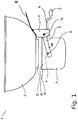
- Fig. 1 schematically shows a side view of the embodiment of the grill device 1, which includes the barbecue fire tank 2 and the ash container 3.
- the ash container 3 is preferably cup-shaped. He is closed down. At the top he has an ash inlet. The circumference of the ash container is designed substantially cylindrical.
- the barbecue fire tank 2 is designed as part of a ball grill.
- the ash container 3 is attached to the grill fire container 2 via a mechanism support 4 and a holder 5.
- the holder 5 comprises a pivoting fork 20 and preferably has at its end directed away from the mechanism support 4 end portion of the pivoting fork 20 has a recess 6, into which engages a fixed to the outer periphery of the ash container 3 pin 7.
- the outer circumference of the pin 7 preferably has a circular cross-section.
- the recess 6 preferably has an at least partially circular contour.
- the recess 6 is arranged on an upper edge of the pivoting fork 20.
- a pressure element 8 is attached in the form of a crank spindle.
- a crank handle 9 is provided at the end of the crank spindle.
- a heat shield 10 may be attached to the grill fire tank 2 between the grill fire tank 2 and the crank handle 9.
- a collar 11 is provided, which is preferably deep-drawn from the material of the bottom of the barbecue fire tank 2. Inside the collar 11 is the ash outlet from the grill fire tank 2.
- the diameter of the collar 11 is slightly smaller than the inner diameter of an upper edge region 12 of the ash container 3.
- the upper edge portion 12 of the ash container 3 is funnel-shaped outwardly cranked, ie it points its upper end an outward rounding 13, which serves as Einfädel Anlagen for insertion of the collar 11 in the ash container 3.
- the end at the outer periphery of the rounding 13 in the vertical direction is more elastic than the cylindrical portion of the ash container 3, so that the outer periphery of the rounding 13 by the greater compliance better close to the bottom of the grill fire tank 2 create and so the air supply in the Inside the grill fire container can complete better.
- the holder 5 and thus the pivoting fork 20 is pivotable about a substantially horizontal pivot axis 14.
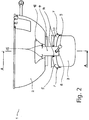
- Fig. 2 shows schematically a front view of the embodiment of the grill device.
- the ash container 3 is provided with two pins 7, which are aligned with each other and are attached to the ash container 3 opposite each other. They are supported by the pivoting fork 20, wherein each one of the pins 7 rests on a leg of the pivoting fork 20.
- the holder 5 preferably has bent or angled portions which form the pivoting fork 20.
- the holder 5 is held by a pivot axis 14, which is preferably carried out with two screws, as a pin with two rivet heads or rivets, wherein the screw or rivet heads in the Fig. 2 you can see.
- the mechanism carrier 4 is, for example, two screws
- Rivets or welds 15 attached to the barbecue fire tank 2. With the rivets or welds 15 at the same time the heat shield 10 may be attached to the barbecue fire tank 2.
- the mechanism support 4 and the heat shield 10 may be integral in one embodiment.
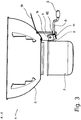
- Fig. 3 schematically shows a cross section of the embodiment of the grill device 1, wherein the cross section in the in Fig. 2 is A - A specified level.
- the Indian Fig. 3 shown cross section passes through the non-cranked part of the crank-shaped rod 8.
- This in the Fig. 3 Part of the rod 8 shown as a left portion is provided in an embodiment with an external thread.
- the external thread of the rod 8 is received in an internal thread of a rivet nut 16.
- This rivet nut can be put into a hole in the Fig. 2 shown front side of the mechanism support 4 be used rotationally.
- the directed to the ash container 3 end of the crank-shaped rod 8 touches a lever 17 of the holder 5 at a force application point.
- the lever 17 preferably extends perpendicular to the pivoting fork leg holding the ash container 3 and downwards from the pivoting axis 14.
- the force application point on the lever 17 is preferably located at a lower portion of the lever 17.
- the pivot axis 14 penetrates the holder 5 in an upper portion of the lever 17th
- a rotation of the crankshaft 8 designed as a crank-shaped rod causes an axial displacement of the same. If the crank-shaped rod 8 moves towards the ash container 3, this causes the ash container 3 to be lifted. In this case, the rotational movement of the crank-shaped rod 8 is converted into an axial translation thereof. This translation causes a pivoting of the holder 5, which in turn ensures a movement of the ash container 3 on a circular path.
- the ash container 3 is oriented horizontally.
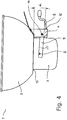
- FIG. 4 schematically shows a side view of the embodiment of the grill device 1 in a position in which the Lucas miclassweg is completely closed by the ambient air to a barbecue in the grill fire tank 2.
- the ash container 3 rests with the rounding 13 at the bottom of the barbecue fire tank 2. As a result, the air passageway is sealed.
- the crank-shaped rod 8 is screwed into the rivet nut 16 to a stop position.
- the lever 17 is thereby pivoted maximally far to the left, as a result of which the holder 5 is displaced maximally upwards.
- the bracket 5 is inclined relative to the bottom of the grill fire tank 2 by an angle ⁇ in a direction in which the end portion of the holder 5 with the recess 6 is closer to the grill fire tank 2 than the portion of the holder 5, to which Pivot axis 14 is arranged.
- the angle ⁇ is preferably about 3 °. With such an angle is advantageously effected a pressing of the ash container 3 to the grill fire tank 2 in a substantially vertical direction.
- the angle in the maximum open position of the ash container 3 relative to the grill fire tank is preferably about 15 °. In the maximum open position, the portion of the holder 5 with the recess 6 is further away from the grill fire container 2 than the portion of the holder 5, on which the pivot axis 14 is arranged.
- FIGS. 5 and 6 Another embodiment of a grill device according to the invention.
- the embodiment according to FIGS. 5 and 6 differs from the above-described embodiment only by a modified moving means for raising and lowering the ash container 3.
- a modified moving means for raising and lowering the ash container 3 for raising and lowering the ash container 3.
- the lever 8 In the second embodiment according to Fig. 5 and Fig. 6 is on the pivoting fork 20 one outwardly projecting rigid lever 8 is provided which is pivotable together with the pivoting fork 20 immediately about the pivot axis 14, as indicated by the double arrow 22.
- the lever 8 passes through a slot housing 24 which is fixed to the mechanism support 4.
- the slot housing 24 has a vertical longitudinal slot 26, which gives the lever 8 a top and bottom limiting pivoting degree of freedom.
- the right-hand outer side 28 of the slot housing 24 this has a circular arc contour, for which the pivot axis 14 represents the center of the circle.
- clamping mechanism 30, 32, 34 z. B. could be replaced by a clamping screw, which is engaged with a provided on the lever rod 8 external thread and clamped instead of the clamping shoe 30 against the slot housing 28 and can be solved therefrom.
- a further variant, not shown, provides that the lever 8 can be mounted in total with the ash container in the mechanism support 4 or unhooked from the mechanism support 4.
- the mechanism carrier on a backdrop for releasably receiving provided on the holder 5, the pivot axis 14 defining the pivot pin.
Landscapes
- Engineering & Computer Science (AREA)
- Food Science & Technology (AREA)
- Baking, Grill, Roasting (AREA)
Claims (14)
- Dispositif de grill (1) comportant une cuve de foyer du grill (2) pour un foyer du grill et un récupérateur de cendre (3) fixé ou pouvant être fixé à la cuve de foyer du grill (2) avec une admission de la cendre, dans lequel l'admission de la cendre est dirigée vers la cuve de foyer du grill, et dans lequel l'apport d'air provenant de l'air environnant vers le foyer du grill peut être réglé par un mouvement relatif entre le récupérateur de cendre (3) et la cuve de foyer du grill (2), dans lequel le mouvement relatif se fait dans le sens vertical et à l'aide du mouvement relatif vertical peuvent être réglées une forme et / ou une dimension d'un trajet de passage d'air limité au moins par le récupérateur de cendre (3) et la cuve de foyer du grill (2), dans lequel pour réaliser le mouvement relatif entre le récupérateur de cendre (3) et la cuve de foyer du grill (2) un dispositif de mouvement (5, 8, 16, 17) avec une attache amovible (5) pour le récupérateur de cendre (3) est fixé directement ou indirectement à la cuve de foyer du grill (2), dans lequel l'attache (5) comprend une fourche pivotante, avec deux branches de fourche portant et logeant entre elles le récupérateur de cendre (3), logée pivotante autour d'un axe de pivotement horizontal (14) par rapport à la cuve de foyer du grill (2), de sorte qu'un mouvement pivotant de la fourche pivotante (20) présente une composante de mouvement vertical respective pour lever et abaisser le récupérateur de cendre (3), et en ce que le dispositif de mouvement (5, 8, 16, 17) présente un élément de manoeuvre (8) pour faire pivoter la fourche pivotante (20) autour de l'axe de pivotement (14), caractérisé en ce que le dispositif de mouvement (5, 8, 16, 17) comprend un mécanisme à mouvement à vis (8, 16) agissant sur l'attache (5), lequel peut être actionné par rotation de l'élément de manoeuvre (8), pour pivoter la fourche pivotante (20) autour de l'axe de pivotement (14) et ainsi régler verticalement le récupérateur de cendre (3) par rapport à la cuve de foyer du grill (2).
- Dispositif de grill selon la revendication 1, caractérisé en ce que le récupérateur de cendre (3) est accroché de manière amovible et articulée à la fourche pivotante (20) de sorte qu'il peut s'orienter horizontalement sous l'effet d'une force de gravité autour d'un axe d'articulation parallèle à l'axe de pivotement (14) de la fourche pivotante (20), lorsque la fourche pivotante (20) est pivotée autour de son axe de pivotement (14).
- Dispositif de grill selon la revendication 1 ou la revendication 2, dans la mesure où ce dernier fait référence à la revendication 2, caractérisé en ce que le dispositif de mouvement est configuré de manière telle que le mécanisme à mouvement à vis (8, 16) agit sur l'attache (5) uniquement par contact lâche sans engagement réciproque de sorte qu'entre le mécanisme à mouvement à vis (8, 16) et l'attache (5) des forces de pression peuvent être transmises pour pivoter la fourche pivotante (20) autour de l'axe de pivotement (14).
- Dispositif de grill selon la revendication 1 ou l'une des revendications 3 à 4 s'y rapportant, caractérisé en ce que le mécanisme à mouvement à vis (8, 16) comprend un arbre de manivelle (8), doté d'un filetage externe, comme élément de manoeuvre et un écrou (16) traversé par l'arbre de manivelle (8) et se trouvant en engagement de filetage avec l'arbre de manivelle (8).
- Dispositif de grill selon la revendication 4, caractérisé en ce que l'écrou (16) est fixé par rapport à la cuve de foyer du grill (2) et l'arbre de manivelle (8) y est logé de façon rotative de sorte que lors de sa rotation il peut être déplacé en avant et en arrière de façon linéaire par vissage pour pivoter la fourche pivotante (20).
- Dispositif de grill selon la revendication 4, caractérisé en ce que l'arbre de manivelle (8) adhère de façon lâche par une extrémité axiale du côté frontal à l'attache (5) et par son autre extrémité fait saillie vers l'extérieur de façon opposée à l'attache (5), l'arbre de manivelle (8) présentant à cette extrémité faisant saillie vers l'extérieur une poignée de commande de manivelle (9).
- Dispositif de grill selon la revendication 2 ou l'une des revendications y faisant référence, caractérisé en ce qu'une liaison d'attache amovible, articulée est réalisée entre le récupérateur de cendre (3) et la fourche pivotante (20) par des évidements en bordure (6) ouverts vers le haut dans la fourche pivotante et des goujons (7) du récupérateur de cendre, logés de façon pivotante à l'intérieur.
- Dispositif de grill selon l'une des revendications précédentes, caractérisé par un support de mécanisme fixé à une cuve de foyer du grill (2) sur laquelle la fourche pivotante (20) est maintenue de façon pivotante autour de son axe de pivotement (14).
- Dispositif de grill selon l'une des revendications précédentes, caractérisé en ce qu'au moins l'élément de manoeuvre (8) est protégé thermiquement de la cuve de foyer du grill (2) par un écran thermique (10).
- Dispositif de grill selon l'une des revendications précédentes, caractérisé en ce que le trajet de passage d'air comprend une ouverture de passage d'air en forme d'au moins une section d'une fente annulaire verticale entre le récupérateur de cendre (3) et la cuve de foyer du grill (2).
- Dispositif de grill selon l'une des revendications précédentes, caractérisé en ce que le trajet de passage d'air passe à travers une section d'étranglement verticale entre une section verticale (11) de la cuve de foyer du grill (2) et une section verticale du récupérateur de cendre (3).
- Dispositif de grill selon l'une des revendications précédentes, caractérisé en ce qu'une hauteur verticale de la section d'étranglement verticale du trajet de passage d'air est réglable.
- Dispositif de grill (1) selon l'une des revendications précédentes, caractérisé en ce que la cuve de foyer du grill (2) présente une sortie de cendre avec une section (11) comportant au moins un écoulement proportionnellement vertical qui est entouré, dans une position soulevée au maximum du récupérateur de cendre (3), radialement à l'extérieur de ce dernier d'une manière obturant le trajet de passage d'air.
- Dispositif de grill selon la revendication 13, caractérisé en ce que la section (11) de la sortie de cendre est une paroi périphérique, annulaire, faisant saillie vers le bas de la cuve de foyer du grill (2), du récupérateur de cendre et en ce que le récupérateur de cendre (3) est coudé radialement vers l'extérieur en forme d'entonnoir sur son bord supérieur (12).
Applications Claiming Priority (2)
| Application Number | Priority Date | Filing Date | Title |
|---|---|---|---|
| DE201310203805 DE102013203805A1 (de) | 2013-03-06 | 2013-03-06 | Grillvorrichtung mit Zuluftsteuerung |
| PCT/EP2014/054239 WO2014135576A1 (fr) | 2013-03-06 | 2014-03-05 | Appareil à grillades à admission d'air réglable |
Publications (2)
| Publication Number | Publication Date |
|---|---|
| EP2802247A1 EP2802247A1 (fr) | 2014-11-19 |
| EP2802247B1 true EP2802247B1 (fr) | 2016-04-13 |
Family
ID=50231166
Family Applications (1)
| Application Number | Title | Priority Date | Filing Date |
|---|---|---|---|
| EP14708022.0A Active EP2802247B1 (fr) | 2013-03-06 | 2014-03-05 | Appareil à grillades à admission d'air réglable |
Country Status (4)
| Country | Link |
|---|---|
| EP (1) | EP2802247B1 (fr) |
| DE (1) | DE102013203805A1 (fr) |
| DK (1) | DK2802247T3 (fr) |
| WO (1) | WO2014135576A1 (fr) |
Families Citing this family (1)
| Publication number | Priority date | Publication date | Assignee | Title |
|---|---|---|---|---|
| DE202013006604U1 (de) * | 2013-07-20 | 2013-08-20 | Steffen Mau | Ofen |
Family Cites Families (12)
| Publication number | Priority date | Publication date | Assignee | Title |
|---|---|---|---|---|
| US3085497A (en) * | 1959-04-10 | 1963-04-16 | Sr Edwin V Statia | Grate-rotating device for portable brazier |
| US3236225A (en) * | 1964-04-03 | 1966-02-22 | Automated Building Components | Barbecue grill plate |
| US4926841A (en) * | 1989-08-17 | 1990-05-22 | Woolf Douglas M | Weather proof ash containment system for barbeques |
| US4966126A (en) | 1989-10-25 | 1990-10-30 | Wu Hsi Liang | Ash-collecting pan and ventilation adjusting device for a barbecue set |
| US5471916A (en) | 1994-08-12 | 1995-12-05 | Porcelain Metals Corporation | Barbeque grill with ash sweep and integral shelf lid holder |
| US5809991A (en) | 1997-10-08 | 1998-09-22 | Pai; Jui-Terng | Ash collector assembly for a barbecue bowl |
| ZA200407318B (en) * | 2004-09-13 | 2006-05-31 | Cadac Pty Ltd | Barbecue arrangement |
| US20060266354A1 (en) | 2005-05-27 | 2006-11-30 | Guthrie Stephen D | Treatment for hepatitis |
| US20060266345A1 (en) | 2005-05-27 | 2006-11-30 | Kiosky Chung | Waste collector for barbecue grill |
| DE202007017595U1 (de) * | 2007-12-18 | 2008-02-28 | König, Benjamin | Grillgerät |
| KR20100118738A (ko) * | 2009-04-29 | 2010-11-08 | 김세웅 | 숯불 화로 |
| KR20110003315U (ko) * | 2009-09-25 | 2011-03-31 | 어파이어 인코포레이티드 | 조리용 화로 |
-
2013
- 2013-03-06 DE DE201310203805 patent/DE102013203805A1/de not_active Ceased
-
2014
- 2014-03-05 EP EP14708022.0A patent/EP2802247B1/fr active Active
- 2014-03-05 WO PCT/EP2014/054239 patent/WO2014135576A1/fr not_active Ceased
- 2014-03-05 DK DK14708022.0T patent/DK2802247T3/en active
Also Published As
| Publication number | Publication date |
|---|---|
| EP2802247A1 (fr) | 2014-11-19 |
| WO2014135576A1 (fr) | 2014-09-12 |
| DK2802247T3 (en) | 2016-07-25 |
| DE102013203805A1 (de) | 2014-09-11 |
Similar Documents
| Publication | Publication Date | Title |
|---|---|---|
| DE2545514C3 (de) | Gleitschiebervorrichtung für mit Bodenauslaßöffnungen versehene Gießgefäße | |
| EP2713816B1 (fr) | Ferrure de placard d'angle | |
| EP2353438A2 (fr) | Armature pour une armoire angulaire | |
| DE102008056475B3 (de) | Mittelarm zur Aufnahme einer Kontaktgrill- oder Bratoberplatte sowie Kontaktgrill- oder Bratgerät mit einem solchen Mittelarm | |
| DE102017220645A1 (de) | Grillgerät | |
| DE102010007287B4 (de) | Beschlag für Eckschränke mit einem Mitnehmer für die Schranktür | |
| EP2802247B1 (fr) | Appareil à grillades à admission d'air réglable | |
| EP3545801B1 (fr) | Machine à boisson avec système de drainage pour eau résiduelle | |
| EP2982441A1 (fr) | Creuset recouvert pour un four d'analyse | |
| EP2713815A1 (fr) | Ferrure de placard d'angle | |
| DE3101865C2 (fr) | ||
| EP1125534B1 (fr) | Système de cuisson avec une construction de tubes | |
| DE676626C (de) | Deckelverschluss fuer Staubsauger | |
| DE60205282T2 (de) | Automatische kaffeezubereitungsvorrichtung | |
| DE102016002505B4 (de) | Vorrichtung zur Aufnahme zumindest eines Gegenstands | |
| DE2142599C3 (de) | Thermostatisch gesteuertes Ventil mit wählbarer Wirkrichtung des Wärmefühlers | |
| DE10213454B4 (de) | Grillvorrichtung | |
| DE1679273C3 (de) | Ölofen mit einer herausführbaren Brennerschale | |
| DE1757948C (de) | Gasfeuerzeug | |
| AT203794B (de) | Tränkebecken | |
| DE3930609A1 (de) | Vorrichtung zum verschwenken einer geraeteaufnahme fuer kuechengeraete oder dergleichen | |
| EP1994973B1 (fr) | Dispositif de filtration d'eau | |
| DE258349C (fr) | ||
| DE3224629C2 (fr) | ||
| DE7441962U (de) | Gasbrenner fuer zahnaerztliche zwecke |
Legal Events
| Date | Code | Title | Description |
|---|---|---|---|
| PUAI | Public reference made under article 153(3) epc to a published international application that has entered the european phase |
Free format text: ORIGINAL CODE: 0009012 |
|
| 17P | Request for examination filed |
Effective date: 20140813 |
|
| AK | Designated contracting states |
Kind code of ref document: A1 Designated state(s): AL AT BE BG CH CY CZ DE DK EE ES FI FR GB GR HR HU IE IS IT LI LT LU LV MC MK MT NL NO PL PT RO RS SE SI SK SM TR |
|
| 17Q | First examination report despatched |
Effective date: 20150123 |
|
| GRAP | Despatch of communication of intention to grant a patent |
Free format text: ORIGINAL CODE: EPIDOSNIGR1 |
|
| DAX | Request for extension of the european patent (deleted) | ||
| INTG | Intention to grant announced |
Effective date: 20151015 |
|
| GRAS | Grant fee paid |
Free format text: ORIGINAL CODE: EPIDOSNIGR3 |
|
| GRAA | (expected) grant |
Free format text: ORIGINAL CODE: 0009210 |
|
| AK | Designated contracting states |
Kind code of ref document: B1 Designated state(s): AL AT BE BG CH CY CZ DE DK EE ES FI FR GB GR HR HU IE IS IT LI LT LU LV MC MK MT NL NO PL PT RO RS SE SI SK SM TR |
|
| REG | Reference to a national code |
Ref country code: GB Ref legal event code: FG4D Free format text: NOT ENGLISH |
|
| REG | Reference to a national code |
Ref country code: AT Ref legal event code: REF Ref document number: 789136 Country of ref document: AT Kind code of ref document: T Effective date: 20160415 Ref country code: CH Ref legal event code: NV Representative=s name: E. BLUM AND CO. AG PATENT- UND MARKENANWAELTE , CH Ref country code: CH Ref legal event code: EP |
|
| REG | Reference to a national code |
Ref country code: IE Ref legal event code: FG4D Free format text: LANGUAGE OF EP DOCUMENT: GERMAN |
|
| REG | Reference to a national code |
Ref country code: DE Ref legal event code: R096 Ref document number: 502014000621 Country of ref document: DE |
|
| REG | Reference to a national code |
Ref country code: SE Ref legal event code: TRGR |
|
| REG | Reference to a national code |
Ref country code: NL Ref legal event code: FP |
|
| REG | Reference to a national code |
Ref country code: DK Ref legal event code: T3 Effective date: 20160718 |
|
| REG | Reference to a national code |
Ref country code: LT Ref legal event code: MG4D |
|
| REG | Reference to a national code |
Ref country code: NO Ref legal event code: T2 Effective date: 20160413 |
|
| PG25 | Lapsed in a contracting state [announced via postgrant information from national office to epo] |
Ref country code: PL Free format text: LAPSE BECAUSE OF FAILURE TO SUBMIT A TRANSLATION OF THE DESCRIPTION OR TO PAY THE FEE WITHIN THE PRESCRIBED TIME-LIMIT Effective date: 20160413 Ref country code: LT Free format text: LAPSE BECAUSE OF FAILURE TO SUBMIT A TRANSLATION OF THE DESCRIPTION OR TO PAY THE FEE WITHIN THE PRESCRIBED TIME-LIMIT Effective date: 20160413 |
|
| PG25 | Lapsed in a contracting state [announced via postgrant information from national office to epo] |
Ref country code: RS Free format text: LAPSE BECAUSE OF FAILURE TO SUBMIT A TRANSLATION OF THE DESCRIPTION OR TO PAY THE FEE WITHIN THE PRESCRIBED TIME-LIMIT Effective date: 20160413 Ref country code: ES Free format text: LAPSE BECAUSE OF FAILURE TO SUBMIT A TRANSLATION OF THE DESCRIPTION OR TO PAY THE FEE WITHIN THE PRESCRIBED TIME-LIMIT Effective date: 20160413 Ref country code: PT Free format text: LAPSE BECAUSE OF FAILURE TO SUBMIT A TRANSLATION OF THE DESCRIPTION OR TO PAY THE FEE WITHIN THE PRESCRIBED TIME-LIMIT Effective date: 20160816 Ref country code: GR Free format text: LAPSE BECAUSE OF FAILURE TO SUBMIT A TRANSLATION OF THE DESCRIPTION OR TO PAY THE FEE WITHIN THE PRESCRIBED TIME-LIMIT Effective date: 20160714 Ref country code: LV Free format text: LAPSE BECAUSE OF FAILURE TO SUBMIT A TRANSLATION OF THE DESCRIPTION OR TO PAY THE FEE WITHIN THE PRESCRIBED TIME-LIMIT Effective date: 20160413 Ref country code: HR Free format text: LAPSE BECAUSE OF FAILURE TO SUBMIT A TRANSLATION OF THE DESCRIPTION OR TO PAY THE FEE WITHIN THE PRESCRIBED TIME-LIMIT Effective date: 20160413 |
|
| REG | Reference to a national code |
Ref country code: DE Ref legal event code: R097 Ref document number: 502014000621 Country of ref document: DE |
|
| PG25 | Lapsed in a contracting state [announced via postgrant information from national office to epo] |
Ref country code: RO Free format text: LAPSE BECAUSE OF FAILURE TO SUBMIT A TRANSLATION OF THE DESCRIPTION OR TO PAY THE FEE WITHIN THE PRESCRIBED TIME-LIMIT Effective date: 20160413 Ref country code: SK Free format text: LAPSE BECAUSE OF FAILURE TO SUBMIT A TRANSLATION OF THE DESCRIPTION OR TO PAY THE FEE WITHIN THE PRESCRIBED TIME-LIMIT Effective date: 20160413 Ref country code: EE Free format text: LAPSE BECAUSE OF FAILURE TO SUBMIT A TRANSLATION OF THE DESCRIPTION OR TO PAY THE FEE WITHIN THE PRESCRIBED TIME-LIMIT Effective date: 20160413 Ref country code: CZ Free format text: LAPSE BECAUSE OF FAILURE TO SUBMIT A TRANSLATION OF THE DESCRIPTION OR TO PAY THE FEE WITHIN THE PRESCRIBED TIME-LIMIT Effective date: 20160413 |
|
| PLBE | No opposition filed within time limit |
Free format text: ORIGINAL CODE: 0009261 |
|
| STAA | Information on the status of an ep patent application or granted ep patent |
Free format text: STATUS: NO OPPOSITION FILED WITHIN TIME LIMIT |
|
| PG25 | Lapsed in a contracting state [announced via postgrant information from national office to epo] |
Ref country code: SM Free format text: LAPSE BECAUSE OF FAILURE TO SUBMIT A TRANSLATION OF THE DESCRIPTION OR TO PAY THE FEE WITHIN THE PRESCRIBED TIME-LIMIT Effective date: 20160413 |
|
| 26N | No opposition filed |
Effective date: 20170116 |
|
| REG | Reference to a national code |
Ref country code: FR Ref legal event code: PLFP Year of fee payment: 4 |
|
| PG25 | Lapsed in a contracting state [announced via postgrant information from national office to epo] |
Ref country code: SI Free format text: LAPSE BECAUSE OF FAILURE TO SUBMIT A TRANSLATION OF THE DESCRIPTION OR TO PAY THE FEE WITHIN THE PRESCRIBED TIME-LIMIT Effective date: 20160413 |
|
| PG25 | Lapsed in a contracting state [announced via postgrant information from national office to epo] |
Ref country code: MC Free format text: LAPSE BECAUSE OF FAILURE TO SUBMIT A TRANSLATION OF THE DESCRIPTION OR TO PAY THE FEE WITHIN THE PRESCRIBED TIME-LIMIT Effective date: 20160413 |
|
| REG | Reference to a national code |
Ref country code: IE Ref legal event code: MM4A |
|
| PG25 | Lapsed in a contracting state [announced via postgrant information from national office to epo] |
Ref country code: LU Free format text: LAPSE BECAUSE OF NON-PAYMENT OF DUE FEES Effective date: 20170305 |
|
| PG25 | Lapsed in a contracting state [announced via postgrant information from national office to epo] |
Ref country code: IE Free format text: LAPSE BECAUSE OF NON-PAYMENT OF DUE FEES Effective date: 20170305 |
|
| REG | Reference to a national code |
Ref country code: BE Ref legal event code: MM Effective date: 20170331 |
|
| REG | Reference to a national code |
Ref country code: FR Ref legal event code: PLFP Year of fee payment: 5 |
|
| PG25 | Lapsed in a contracting state [announced via postgrant information from national office to epo] |
Ref country code: BE Free format text: LAPSE BECAUSE OF NON-PAYMENT OF DUE FEES Effective date: 20170331 |
|
| PG25 | Lapsed in a contracting state [announced via postgrant information from national office to epo] |
Ref country code: MT Free format text: LAPSE BECAUSE OF FAILURE TO SUBMIT A TRANSLATION OF THE DESCRIPTION OR TO PAY THE FEE WITHIN THE PRESCRIBED TIME-LIMIT Effective date: 20160413 |
|
| PG25 | Lapsed in a contracting state [announced via postgrant information from national office to epo] |
Ref country code: AL Free format text: LAPSE BECAUSE OF FAILURE TO SUBMIT A TRANSLATION OF THE DESCRIPTION OR TO PAY THE FEE WITHIN THE PRESCRIBED TIME-LIMIT Effective date: 20160413 |
|
| PGFP | Annual fee paid to national office [announced via postgrant information from national office to epo] |
Ref country code: IT Payment date: 20190123 Year of fee payment: 12 |
|
| PG25 | Lapsed in a contracting state [announced via postgrant information from national office to epo] |
Ref country code: HU Free format text: LAPSE BECAUSE OF FAILURE TO SUBMIT A TRANSLATION OF THE DESCRIPTION OR TO PAY THE FEE WITHIN THE PRESCRIBED TIME-LIMIT; INVALID AB INITIO Effective date: 20140305 |
|
| PG25 | Lapsed in a contracting state [announced via postgrant information from national office to epo] |
Ref country code: BG Free format text: LAPSE BECAUSE OF FAILURE TO SUBMIT A TRANSLATION OF THE DESCRIPTION OR TO PAY THE FEE WITHIN THE PRESCRIBED TIME-LIMIT Effective date: 20160413 |
|
| PG25 | Lapsed in a contracting state [announced via postgrant information from national office to epo] |
Ref country code: CY Free format text: LAPSE BECAUSE OF FAILURE TO SUBMIT A TRANSLATION OF THE DESCRIPTION OR TO PAY THE FEE WITHIN THE PRESCRIBED TIME-LIMIT Effective date: 20160413 |
|
| PG25 | Lapsed in a contracting state [announced via postgrant information from national office to epo] |
Ref country code: MK Free format text: LAPSE BECAUSE OF FAILURE TO SUBMIT A TRANSLATION OF THE DESCRIPTION OR TO PAY THE FEE WITHIN THE PRESCRIBED TIME-LIMIT Effective date: 20160413 |
|
| PG25 | Lapsed in a contracting state [announced via postgrant information from national office to epo] |
Ref country code: TR Free format text: LAPSE BECAUSE OF FAILURE TO SUBMIT A TRANSLATION OF THE DESCRIPTION OR TO PAY THE FEE WITHIN THE PRESCRIBED TIME-LIMIT Effective date: 20160413 |
|
| PGFP | Annual fee paid to national office [announced via postgrant information from national office to epo] |
Ref country code: NO Payment date: 20200326 Year of fee payment: 7 Ref country code: FI Payment date: 20200320 Year of fee payment: 7 Ref country code: GB Payment date: 20200323 Year of fee payment: 7 Ref country code: SE Payment date: 20200323 Year of fee payment: 7 |
|
| PG25 | Lapsed in a contracting state [announced via postgrant information from national office to epo] |
Ref country code: IS Free format text: LAPSE BECAUSE OF FAILURE TO SUBMIT A TRANSLATION OF THE DESCRIPTION OR TO PAY THE FEE WITHIN THE PRESCRIBED TIME-LIMIT Effective date: 20160813 |
|
| REG | Reference to a national code |
Ref country code: FI Ref legal event code: MAE |
|
| REG | Reference to a national code |
Ref country code: NO Ref legal event code: MMEP |
|
| PG25 | Lapsed in a contracting state [announced via postgrant information from national office to epo] |
Ref country code: FI Free format text: LAPSE BECAUSE OF NON-PAYMENT OF DUE FEES Effective date: 20210305 Ref country code: IT Free format text: LAPSE BECAUSE OF NON-PAYMENT OF DUE FEES Effective date: 20200305 |
|
| GBPC | Gb: european patent ceased through non-payment of renewal fee |
Effective date: 20210305 |
|
| PG25 | Lapsed in a contracting state [announced via postgrant information from national office to epo] |
Ref country code: GB Free format text: LAPSE BECAUSE OF NON-PAYMENT OF DUE FEES Effective date: 20210305 Ref country code: SE Free format text: LAPSE BECAUSE OF NON-PAYMENT OF DUE FEES Effective date: 20210306 Ref country code: NO Free format text: LAPSE BECAUSE OF NON-PAYMENT OF DUE FEES Effective date: 20210331 |
|
| REG | Reference to a national code |
Ref country code: DE Ref legal event code: R081 Ref document number: 502014000621 Country of ref document: DE Owner name: ROSLE GROUP GMBH, DE Free format text: FORMER OWNER: METALLWARENFABRIK MARKTOBERDORF GMBH & CO. KG, 87616 MARKTOBERDORF, DE |
|
| PGFP | Annual fee paid to national office [announced via postgrant information from national office to epo] |
Ref country code: CH Payment date: 20220321 Year of fee payment: 9 |
|
| REG | Reference to a national code |
Ref country code: NL Ref legal event code: PD Owner name: ROESLE GROUP GMBH; DE Free format text: DETAILS ASSIGNMENT: CHANGE OF OWNER(S), ASSIGNMENT; FORMER OWNER NAME: METALLWARENFABRIK MARKTOBERDORF GMBH & CO. KG Effective date: 20220426 |
|
| REG | Reference to a national code |
Ref country code: AT Ref legal event code: PC Ref document number: 789136 Country of ref document: AT Kind code of ref document: T Owner name: ROESLE GROUP GMBH, DE Effective date: 20220411 |
|
| PGFP | Annual fee paid to national office [announced via postgrant information from national office to epo] |
Ref country code: NL Payment date: 20220321 Year of fee payment: 9 |
|
| REG | Reference to a national code |
Ref country code: CH Ref legal event code: PL |
|
| REG | Reference to a national code |
Ref country code: NL Ref legal event code: MM Effective date: 20230401 |
|
| PG25 | Lapsed in a contracting state [announced via postgrant information from national office to epo] |
Ref country code: NL Free format text: LAPSE BECAUSE OF NON-PAYMENT OF DUE FEES Effective date: 20230401 |
|
| PG25 | Lapsed in a contracting state [announced via postgrant information from national office to epo] |
Ref country code: LI Free format text: LAPSE BECAUSE OF NON-PAYMENT OF DUE FEES Effective date: 20230331 Ref country code: CH Free format text: LAPSE BECAUSE OF NON-PAYMENT OF DUE FEES Effective date: 20230331 |
|
| P01 | Opt-out of the competence of the unified patent court (upc) registered |
Free format text: CASE NUMBER: UPC_APP_118654/2023 Effective date: 20230510 |
|
| PGFP | Annual fee paid to national office [announced via postgrant information from national office to epo] |
Ref country code: DE Payment date: 20250225 Year of fee payment: 12 |
|
| PGFP | Annual fee paid to national office [announced via postgrant information from national office to epo] |
Ref country code: DK Payment date: 20250326 Year of fee payment: 12 |
|
| PGFP | Annual fee paid to national office [announced via postgrant information from national office to epo] |
Ref country code: AT Payment date: 20250320 Year of fee payment: 12 |
|
| PGFP | Annual fee paid to national office [announced via postgrant information from national office to epo] |
Ref country code: FR Payment date: 20250325 Year of fee payment: 12 |